US6461268B1 - Continuously variable transmission device - Google Patents
Continuously variable transmission deviceDownload PDFInfo
- Publication number
- US6461268B1 US6461268B1US09/600,271US60027100AUS6461268B1US 6461268 B1US6461268 B1US 6461268B1US 60027100 AUS60027100 AUS 60027100AUS 6461268 B1US6461268 B1US 6461268B1
- Authority
- US
- United States
- Prior art keywords
- race
- members
- parts
- drive
- transmission device
- Prior art date
- Legal status (The legal status is an assumption and is not a legal conclusion. Google has not performed a legal analysis and makes no representation as to the accuracy of the status listed.)
- Expired - Lifetime
Links
- 230000005540biological transmissionEffects0.000titleclaimsabstractdescription184
- 238000005096rolling processMethods0.000claimsabstractdescription88
- 238000000926separation methodMethods0.000claimsabstractdescription57
- 230000033001locomotionEffects0.000claimsdescription32
- 238000006073displacement reactionMethods0.000claimsdescription16
- 230000008859changeEffects0.000claimsdescription5
- 230000010006flightEffects0.000claimsdescription4
- 230000007246mechanismEffects0.000description24
- 230000007935neutral effectEffects0.000description18
- 230000000694effectsEffects0.000description7
- 238000006243chemical reactionMethods0.000description6
- 230000008901benefitEffects0.000description5
- 230000009471actionEffects0.000description4
- 230000008878couplingEffects0.000description3
- 238000010168coupling processMethods0.000description3
- 238000005859coupling reactionMethods0.000description3
- 239000012530fluidSubstances0.000description3
- 238000005461lubricationMethods0.000description3
- 230000036316preloadEffects0.000description3
- 240000005002Erythronium dens canisSpecies0.000description2
- 239000000314lubricantSubstances0.000description2
- 230000009467reductionEffects0.000description2
- 244000258271Galium odoratumSpecies0.000description1
- 235000008526Galium odoratumNutrition0.000description1
- 230000009286beneficial effectEffects0.000description1
- 238000002485combustion reactionMethods0.000description1
- 239000002131composite materialSubstances0.000description1
- 230000006835compressionEffects0.000description1
- 238000007906compressionMethods0.000description1
- 230000009351contact transmissionEffects0.000description1
- 230000001419dependent effectEffects0.000description1
- 238000005516engineering processMethods0.000description1
- 239000004519greaseSubstances0.000description1
- 238000007373indentationMethods0.000description1
- 230000001788irregularEffects0.000description1
- 230000001050lubricating effectEffects0.000description1
- 238000012423maintenanceMethods0.000description1
- 238000000034methodMethods0.000description1
- 230000002093peripheral effectEffects0.000description1
- 230000037452primingEffects0.000description1
- 230000000750progressive effectEffects0.000description1
Images


Classifications
- F—MECHANICAL ENGINEERING; LIGHTING; HEATING; WEAPONS; BLASTING
- F16—ENGINEERING ELEMENTS AND UNITS; GENERAL MEASURES FOR PRODUCING AND MAINTAINING EFFECTIVE FUNCTIONING OF MACHINES OR INSTALLATIONS; THERMAL INSULATION IN GENERAL
- F16H—GEARING
- F16H15/00—Gearings for conveying rotary motion with variable gear ratio, or for reversing rotary motion, by friction between rotary members
- F16H15/48—Gearings for conveying rotary motion with variable gear ratio, or for reversing rotary motion, by friction between rotary members with members having orbital motion
- F16H15/50—Gearings providing a continuous range of gear ratios
- F16H15/52—Gearings providing a continuous range of gear ratios in which a member of uniform effective diameter mounted on a shaft may co-operate with different parts of another member
- F—MECHANICAL ENGINEERING; LIGHTING; HEATING; WEAPONS; BLASTING
- F16—ENGINEERING ELEMENTS AND UNITS; GENERAL MEASURES FOR PRODUCING AND MAINTAINING EFFECTIVE FUNCTIONING OF MACHINES OR INSTALLATIONS; THERMAL INSULATION IN GENERAL
- F16H—GEARING
- F16H15/00—Gearings for conveying rotary motion with variable gear ratio, or for reversing rotary motion, by friction between rotary members
- F16H15/48—Gearings for conveying rotary motion with variable gear ratio, or for reversing rotary motion, by friction between rotary members with members having orbital motion
- F16H15/50—Gearings providing a continuous range of gear ratios
Definitions
- the present inventionrelates generally to a continuously variable transmission device, and particularly to such a device in which forces are transmitted by rolling traction.
- One known type of continuously variable transmissionwhich has been put into commercial use in the drive train of a motor vehicle comprises a transmission belt of trapezoidal section passing around two split pulleys the opposite halves of which have facing inclined conical surfaces and are urged towards one another such that the effective transmission ratio between one pulley and the next is determined by the relative separation of the two parts of the pulleys. On being moved apart, the two parts of a pulley allow the belt to contact the conical faces at a radially inner position thereby changing the transmission ratio.
- continuously variable transmissionOther forms of continuously variable transmission are known, for example from U.S. Pat. No. 1,800,388.
- the present inventionseeks to provide a continuously variable transmission in which the forces are transmitted between the members in motion by rolling contact. This minimises the amount of wear to which the members are subject upon changing the transmission ratio, and allows a continuously variable transmission to be made which is easy to control, requires low maintenance and offers a durable mechanism with a long service life.
- a continuously variable transmission deviceof the type having planet members in rolling contact with radially inner and outer races each comprising two axially spaced parts, with control means for selectively varing the axial separation of the two parts of one race and thus the radial position of the planet members in rolling contact therewith, in which there are provided means sensitive to the torque applied to a drive-transmitting member of the transmission operable both to determine the compensating variation in the separation of the two parts of the other race and thus the transmission ratio of the device and to vary the forces exchanged between the planets and the races normal to the interface between them.
- the planet membersare substantially spherical bodies. They may be right circular, oblate or prolate spheroids. Alternatively, the planet members may have respective first and second surface portions comprising surfaces of revolution about the same axis (for each member) the surface portions being inclined with respect to one another in opposite directions about the axes of revolution.
- the planet membersmay have a convex or concave surface of revolution defined by a curved generatrix which may be a regular or irregular curve or a part-circular curve. In the case of a part-circular generatrix this may be a semi-circle, in which case the surface of revolution of the planet member is spherical.
- the inner and outer racespreferably comprises two parts, one in contact with each of the first and second portions respectively, and each having a respective surface constituted by a surface of revolution about a common axis and inclined in opposite directions with respect to the said axis.
- the two parts of one of the inner or outer racesmay be supported in such a way as to be relatively displaceable towards or away from one another whereby to vary the radius of the point or line of contact between the said one race and the planet members.
- Embodiments of the inventionmay be provided with torque-sensitive mechanical coupling means interposed between an input drive member and one of the races whereby to balance the torque transmission and the contact pressures between the two parts of that race and the planet members.
- the planet membersare substantially spherical and captive between the radially inner races and the radially outer races, there being roller follower members circumferentially intercalated between adjacent pairs of planet members for transmitting drive to or from the said planet members.
- roller follower membersare carried on a planet carrier member to which drive to or from the planet members is transmitted in operation of the device.
- the present inventionprovides a drive transmission device as defined above, in which the axes of rotation of the planet members about their own axis are substantially parallel to the axis of rotation of the planets about the radially inner race.
- the axis of rotation of the radially inner raceis substantially parallel to the axis of the means defining the radially outer race defining the planetary path of the planet members.
- the means for selectively varying the axial separation of the two parts of the radially inner race or the means defining the radially outer raceinclude two adjustment members interconnected by a helical interengagement such that relative turning motion of one of the adjustment members results in relative axial displacement of the other.
- the helical interengagement of the two adjustment memberscomprises a screw threaded engagement of the members themselves, the said one of the two adjustment members being turnable through at least a limited arc of movement about a first axis and the said other of the adjustment members being restrained against rotary motion at least about an axis substantially parallel to the said first axis.
- the helix anglemay be constant over the entire length of the helix although for certain applications it may be found to be useful if the helix angle of the said helical interengagement varies over the circumferential extent of the helix.
- the said other of the two adjustment membersis or is carried by or on the said means defining the radially outer track.
- the two parts of the radially inner racemay be carried on a drive or driven shaft, and the means for allowing relative separation of the two parts of the radially inner race comprise at least one inclined surface acting to react the forces exerted by the transmission of drive forces between the radially inner race and the planet members.
- the said inclined surfacemay be part of a helical interengagement between the parts of the radially inner race and the drive shaft.
- the helix anglemay be constant or may vary over the length of the helix.
- helixis constant or varying its form and helix angle should preferably be such that the circumferential component of the axial force reacted by the helix is substantially equal to and opposite in sign from the direct circumferential force reacted by the helix such that the force required to be applied to the said selective adjustment means to maintain or change a transmission ratio is minimised.
- the present inventionalso comprehends an infinitely variable transmission device comprising a continuously variable transmission as defined above together with a further epicyclic transmission train of fixed ratio gears or rolling traction members the dimensions of which are such that the effective radius of contact between the gears about the axes of the input shaft lies at a radius between the maximum and minimum radius of the line of contact between the radially inner race and the planets at opposite ends of the range of adjustment of the continuously variable transmission.
- the present inventionprovides a rolling contact continuously variable transmission device of the type having planetary members in rolling contact with radially inner and outer races each comprising two relatively axially displaceable race parts, in which the planetary members are substantially spherical and the transmission forces to or from the spherical planetary members in planetary motion is effected via roller follower members.
- roller follower membersare each interposed between respective pairs of adjacent planetary members and carried on a planet carrier member through which drive to or from the planet members is transmitted in operation of the device.
- the rolling contact continuously variable transmission device of the inventionmay be considered, in one aspect, as a variable geometry four point contact rolling element bearing in which power transfer takes place between two or three principal bearing elements comprising a radially inner race, a radially outer race and a planet carrier or cage; a fourth bearing element being provided, usually fixed, for torque reaction.
- a transmission device formed as an embodiment of the inventionthe axial separation of the race which compensates for adjustment of the other is therefore determined in essence by the forces applied to the said other race elements.
- Such a continuously variable transmissionmay be combined with an epicyclic gear train to provide an infinitely variable transmission which has a transmission ratio varying from a negative value or nil to a maximum value determined by the dimensions of the device. It is also possible so to chose the relative shapes of the contacting surfaces of the races and the rolling elements that a so-called “geared” neutral position can be achieved in which no transmission of motion takes place despite the rotation of the drive member.
- Such a configurationalso, therefore, allows the rolling elements to be in such neutral position at an intermediate point in their overall range of movement (which movement is determined by the controlled separation of that pair of the race members to which input control forces are applied) thereby allowing relative rotation of the input and output drive members in the same or in opposite directions depending on the adjustment of the transmission. This effectively results in the provision of forward and reverse drive ratios on either side of a neutral ratio.
- Embodiments of the present inventioncan be made in which incremental control of the gear ratios is achieved by various means whereby to simulate a stepped gearbox.
- a control mechanism by which the separation of the two controlling raceways is determinedhas an incremental adjustment device or indexing mechanism allowing it to be displaced between several discrete predetermined positions.
- the contacting surface of some of the racewaysmay be shaped such that the forces exerted on the rolling elements tend to drive them to one of a limited number of predetermined positions.
- a “geared” neutralhas many advantages in a transmission device such as that defined herein inevitable tolerances may result in their being a certain amount of “creep” in either direction when the transmission device is set in its neutral position. To combat this it may be advantageous to provide means by which a “disconnected” neutral ratio may be achieved in which there is a positive break in the transmission chain allowing certainty in the selection of a neutral gear that no drive transmission will take place.
- a disconnected neutralmay be achieved in one aspect of the present invention by the addition of a relatively rotatable member or corresponding members, to either the radially inner or radially outer raceway contactable by the rolling elements over a certain part of the range of movement thereof in adjustment of the drive transmission.
- a relatively rotatable member or corresponding membersto either the radially inner or radially outer raceway contactable by the rolling elements over a certain part of the range of movement thereof in adjustment of the drive transmission.
- a disconnected neutralmay also be achieved by mounting one of the parts of the raceway in such a way that it can be withdrawn from its working position by a distance such as to release the pressure on the rolling elements at the time. This allows, in effect, a “declutching” action to be achieved with the transmission device set in any gear ratio.
- a similar arrangementmay be provided for a so-called “launch” control that is for progressive engagement of the transmission device from neutral to a drive gear ratio, and this can be achieved effectively by providing a range of motion of a ratio control member between the geared neutral position and a first detent or stop defining a lowermost gear ratio.
- the drive transmission from an input shaft to an output shaftcan only take place in one direction of rotation.
- the torque-sensing mechanismwhich in one embodiment involves a helical interengagement between one of the two race parts in the said other race and a cooperating component allows the two race parts to be urged towards one another by the forces exerted on them in operation only when the direction of rotation of the input shaft corresponds to that of the helical interengagement.
- Relative rotation between the input shaft and the output shaft in the opposite directionwould result in a relative separation of the other race parts which would effectively result in a reduction in the contact forces and, ultimately, to a decoupling of the input and output members.
- the present inventionalso seeks, therefore, to provide a continuously variable transmission device of the type described herein in which the transmission of torque from an input to an output shaft can take place in either direction of rotation.
- a continuously variable transmission device of the typehaving planetary members in rolling contact with radially inner and outer races each comprising two axially spaced parts, with control means for selectively varying the axial separation of the two parts of one race and thus the radial position of the planetary members in rolling contact therewith, in which there are provided means sensitive to the torque applied to a drive-transmitting member of the transmission device, operable both to determine the compensating variation in the separation of the two parts of the other race and thus the transmission ratio of the device and to vary the forces exchanged between the planets and the races normal to the interface between them, and in which the said torque-sensitive means include the two axially spaced, relatively moveable parts of the said other race, each said part being itself axially movable in two directional senses from a central position and engagable by limit stop means whereby to allow the transmission of rotary drive from a rotary drive input member to a rotary drive output member of the transmission device in each of two opposite
- the said relatively movable race parts of the torque-sensitive meansare interconnected with the input drive member by a screw-thread engagement of the same hand by which rotary drive is transmitted when axial displacement of a race part is restrained.
- the thread flights of the screw thread engagementare preferably interengaged by rolling elements such as balls although this is not essential.
- rolling elementssuch as balls although this is not essential.
- the provision of interengaging ballshelps significantly to reduce frictional resistance in the device.
- the said two relatively movable race parts of the torque-sensitive meansmay be oppositely axially resiliently biased.
- This resilient biasact to “prime” the torque-sensing reaction of the device and in a preferred embodiment of the invention the resilient biasing of the said two relatively movable race parts is achieved by a compression spring located between them.
- each of the two race partsmust ultimately be restrained from axial movement such that the other race part can, effectively “screw up” against it by the helical action exerted on it by the input member.
- limit stop meansmay comprise respective abutments on or carried by or associated with the said input drive member.
- the two race parts of the said one race of the transmission deviceare each carried on a casing of the transmission device in such a way as to have a limited rotational displacement in each of two opposite rotational senses.
- the relative axial separation of the two race parts of the said one racemay be achieved by a helical interengagement of at least one of the two race parts with a fixed member of the transmission device, the two race parts both being relatively turnable with respect to the said fixed member.
- Such relative turning movement of the two race parts of the said one racemay be achieved by any means which act directly between them rather than between one member and a fixed part.
- One means by which this can be achievedcomprises a Bowden cable acting between the two race parts.
- the present inventionalso comprehends, independently of the structure allowing bi-directional rotation to be achieved, a continuously variable transmission device of the type having planetary members in rolling contact with radially inner and outer races each comprising two axially spaced parts, with control means for selectively varying the axial separation of the two parts of one race and thus the radial position of the planetary members in rolling contact therewith, in which the planetary members each have a circumferential annular groove the axis of which substantially coincides with the respective rolling axis about which each planetary member turns as it rolls in contact with the races, the said annular grooves being engaged by roller follower members acting to guide the planetary members to maintain their orientation in their planetary motion.
- This latter featureenables a greater load-carrying capacity to be achieved because a greater number of planetary members can be arranged in a given annular space because the circumferential space occupied by a planetary member can overlap that occupied by a planet follower.
- the planet followersare preferably carried by a common carrier member through which drive transmission is conveyed to an output drive member of the device.
- a continuously variable transmission device of the typehaving planetary members in rolling contact with radially inner and outer races each comprising two axially spaced parts, with control means for selectively varying the axial separation of the two parts of one race and thus the radial position of the planetary members in rolling contact therewith, has planetary members each with arcuately curved surface portions in rolling contact with correspondingly curved portions of the respective races, the radius of curvature of the said surface portions of the planetary members being greater than the effective radius of the planetary member itself.
- Such planetsmay also be formed with circumferential grooves for receiving roller follower guide members as discussed above. There may further be provided means for guiding the planetary members to maintain the orientation of their rolling axes as they roll over the contacting surfaces of the races. Such guide members may be the above-mentioned rollers engaged in the circumferential grooves.
- the purpose of enlarging the radius of curvature of the surface portions in relation to the diameter of the planetary member itself,is to extend the range of ratios which can be transmitted by the transmission device.
- the ratio rangecan be extended to 4.3:1.
- a continuously variable transmission device of the typehaving planetary members in rolling contact with radially inner and outer races each comprising two axially spaced parts, with control means for selectively varying the axial separation of the two parts of one race and thus the radial position of the planetary members in rolling contact therewith, in which each planetary member has a plurality of elementary annular contact surface portions having a substantially constant inclination to the rolling axis of the planetary member itself.
- the racesmay have substantially continuously curved contact surfaces or may have respective contact surfaces for rolling contact with the planetary members, each having correspondingly inclined elementary annular contact surface portions substantially matching those of the planetary members.
- FIG. 1is a schematic axial section of the major component of a rolling contact continuously variable transmission device useful for explaining the principle of operation of the device;
- FIG. 2is a schematic axial view of the transmission device seen from the direction of the arrow A of FIG. 1;
- FIGS. 3 and 4are schematic axial sections similar to FIG. 1 and respectively showing the transmission device in this configuration for the highest transmission ratio and that for the lowest transmission ratio;
- FIG. 5is an axial sectional view of a continuously variable rolling contact transmission device formed as a first embodiment of the present invention
- FIG. 6is a schematic axial sectional view showing a rolling contact continuously variable transmission device incorporated in an infinitely variable transmission device
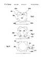
- FIG. 7is an axial sectional view of a further embodiment of the invention suitable for use as a bicycle hub gear transmission
- FIGS. 8, 9 and 10are schematic partial axial sectional views of various different raceway configurations useful for various specific applications
- FIGS. 11 and 12are schematic axial sectional views of alternative embodiments having different planetary members
- FIG. 13is an axial sectional view through a first embodiment of the present invention.
- FIG. 14is a cross-sectional view taken on the line XIII—XIII of FIG. 13;
- FIGS. 15 and 16are schematic detail views showing components of the embodiment of FIGS. 13 and 14 in two different operating configurations
- FIG. 17is a schematic cross-sectional view of the embodiment of FIG. 13 showing the relative positions of an adjustment mechanism
- FIG. 18is an axial sectional view of an alternative embodiment of the invention.
- FIGS. 19-24are schematic views of a detail of the embodiment of FIG. 18 showing the components in different configurations for achieving different gear ratios.
- the continuously variable transmission mechanism of the inventionis formed as a variable radius epicyclic mechanism having rolling traction torque transfer with the advantage that the shaft bearings and housing are not subject to large forces and the moving parts can be based on traditional roller and ball bearing technology. It also has the advantages that it includes a purely mechanical preload and torque sensing system and that it can be splash or grease lubricated by a known traction fluid lubricant without requiring special lubricating techniques. As will be appreciated from the more detailed description which follows, the control of the transmission ratio can be effected by a simple mechanical device.
- the variable radius epicyclical transmission device in FIGS. 1 to 4comprises a housing (not shown for simplicity) within which is mounted an input shaft 11 bearing rolling element bearings 12 , 13 within a planet cage 14 carrying three planet follower members 15 .
- the planet follower members 15are rotatably borne on the planet cage 14 by planet follower shafts 16 .
- the planet cage 14is effectively constituted by two radial plates 14 a , 14 b joined together by shouldered studs 16 forming the said planet follower shafts and secured by nuts 20 , 21 at each end to form a cage.
- An axial cylindrical extension 22 of the radial plate 14 b of the planet carrier 14constitutes the output shaft of the transmission mechanism.
- a radially inner race 23constituting a sun member comprising two parts 23 a , 23 b which are engaged to the shaft 11 by means of a coupling comprising a helical interengagement in the form of a screw threaded engagement.
- the two race parts 23 a and 23 bhave oppositely handed threads so that, for reasons which will be descried in more detail below, a relative rotation of the input shaft 11 and the inner race parts 23 a , 23 b in one directional sense will cause the two parts to be displaced towards one another whereas axial separation of the two parts 23 a , 23 b of the inner raceway occurs where there is relative rotation between them and the input shaft 11 in the opposite directional sense.
- Three spherical planetary members 25are engaged between the inner raceway 23 and an outer raceway 26 also comprising two axially separated annular raceway members 26 a , 26 b .
- Rolling tracks of the raceway members 23 a , 23 b and 26 a , 26 b , respectively identified 27 a , 27 b and 28 a , 28 beach comprise, in cross-section, a part-circular arcuate surface the radius of which is slightly greater than the radius of the spherical planetary members 25 .
- the outer raceway members 26 a , 26 bare engaged by an axial adjustment mechanism generally indicated 29 and schematically shown in FIG. 1 as a lever 30 pivotally mounted on a reaction member 31 such that turning the lever in one direction or the other about a pivot 32 by which it is connected to the reaction member 31 , and as shown by the double arrow B of FIG. 1, causes the two raceway parts 26 a , 26 b to be urged axially towards one another or allowed to separate axially from one another.
- the raceway 26is provided with means for preventing its rotation about the axis X—X which is the common axis of rotation of the input shaft 11 , the inner and outer raceways 23 , 26 , the output shaft 22 and the spherical planetary members 25 .
- the helical interengagement between the radially inner raceway parts 23 a , 23 b and the input shaft 11acts in effect as a torque-sensitive mechanism in that the helical interengagement is such that rotation of the shaft 11 in the intended direction of drive causes the raceway parts 23 a , 23 b to approach one another axially when resisted by drag so that any play in the rolling contact between the raceways and the planetary balls 25 is taken up and compensated by the tendency of the raceway parts 23 a , 23 b to approach one another until the forces exerted on the helical interengagement between the raceway parts 23 a , 23 b and the drive shaft 11 matches the reaction forces between the raceway parts 23 a , 23 b and the planetary balls 25 , at which point no further relative axial displacement of the raceway parts 23 a , 23 b takes place and drive transmission takes place at a transmission ratio determined by the radial position of the balls 25 when this occurs.
- the continuously variable transmission mechanism described aboveis extremely compact and highly efficient, and has no need for a pressurised hydraulic circuit for either lubrication or control purposes in order to achieve the required function. It can be in modular form and is scalable readily to accommodate both large and small size applications.
- the input shaft 11could be considered as a unitary member there would be no way in which the two parts 23 a , 23 b of the inner race could be fitted over the unthreaded ends of the shaft 11 .
- Thiscould be achieved by forming the input shaft 11 as composite member with the unthreaded parts assembled to the threaded parts after the sun members 23 a , 23 b has been fitted thereto.
- the shaft 11may simply be of smaller diameter, at the end portions which are not threaded, to match the radially innermost dimension of the thread flights allowing the sun parts 23 a , 23 b to be slid along them upon assembly.
- FIG. 5there is shown a practical embodiment in which this adjustment is achieved in a way which applies the adjustment forces symmetrically around the entire periphery of the radially outer raceways.
- the structure of this embodimentis based on the realisation that the forces exerted by the spherical planets 25 do not need to be transferred through two planet carrier plates such as 14 a , 14 b of FIG. 1 but that they are sufficiently balanced to allow only a single planet carrier plate to be utilised providing that the input shaft 11 is provided with suitable bearings in order to prevent axial misalignment.
- the input or drive shaft 11carries the variable transmission unit in its entirety.
- Such an embodimentis suitable, for example, as the gear transmission from a moped or motor cylce to drive a wheel via a chain drive.
- the output drive member from the variable transmissionis a chain wheel 33 carried on an external casing 34 secured to the periphery of the planet carrier 14 which, in this embodiment, comprises a single disc having shafts 16 projecting therefrom.
- the shafts 16do not pass right through the space between the inner and outer races 23 , 26 .
- the drive shaft 11may, for example, be the output shaft from an internal combustion engine or other prime mover. It has a projecting end portion 25 of smaller diameter than the main part of the shaft 11 carrying one of the two parts (in this case the part 23 a ) of the inner raceway 23 secured for rotation with the shaft 11 by a woodruff key 36 .
- the raceway parts 23 ais fixed for rotation with the shaft 11 and has an axially extending sleeve 23 c over which the second raceway part 23 b is fitted.
- the outer cylindrical surface of the sleeve 23 c and the inner cylindrical surface of the second radially inner raceway part 23 bare provided with matching helical channels 37 , 38 of semicircular cross-section housing a plurality of balls 39 . Relative axial separation or approach of the two raceway parts 23 a , 23 b can be achieved, therefore, by relative rotation of these two parts about the axis of the drive shaft 11 .
- a light spring 40 engaged between the second of the radially inner raceway parts 23 b and a stationary housing 41provides a light pre-loading of the second radially inner raceway part 23 b to ensure that this always maintains contact with the spherical planets 25 even in no load conditions so that the radially inner raceway parts 23 a , 23 b do not become axially separated by such a distance that the spherical planets 25 become loose and rattle within the track defined by the radially inner and outer races 23 , 26 .
- the radially outer race 26comprises a first part 26 a which has an axially extending sleeve 42 within which the second of the radially outer raceway parts 26 b is fitted.
- the inner surface of the cylindrical sleeve 42has a helical ridge 43 of rectangular cross-section and the second radially outer raceway part 26 b has on its outer cylindrical surface a helical channel 44 of corresponding rectangular cross-section.
- the ridge 43 and channel 44form a robust scroll similar in configuration to an “ajax” screw thread.
- the first radially outer raceway part 26 ais rotatably fixed but axially free on a cylindrical outer wall 45 of the fixed housing 41 which carries a projecting lug 47 on which is supported a torque-reaction arm 48 which engages a fixed part of the framework of the vehicle to maintain the housing 41 stationary (that is non-rotating) with respect to the vehicle.
- the housing 41also carries a second projecting lug 45 which, in this case, is hollow and receives a shaft 50 one end of which projects out from the casing 41 and carries a control lever 51 and the other end of which projects into the casing and carries a lever 52 the free end of which is secured to the second radially outer raceway part 26 b .
- Movement of the control lever 51 about the axis of the pivot pin SOcauses the lever 52 to turn correspondingly and thus cause the raceway part 26 b to turn about the axis of the device, which is coincident with the axis of the input drive shaft 11 , with respect to the fixed radially outer raceway part 26 a .
- This movementis converted by the helical interengagement constituted by the helical channels 44 and helical rib 43 into axial approach or separation of the two radially outer raceway parts 26 a , 26 b.
- Rotation of the drive shaft 11thus causes the radially inner race 23 to rotate and carry with it, by rolling contact, the planetary spheres 25 which roll also over the curved surfaces of the radially outer race 26 .
- the planetary spheres 25are constrained only by their contact with the curved surfaces 27 a , 27 b and 28 a , 28 b of the radially inner and radially outer races 23 , 26 respectively but each pair of planetary spheres 25 has a roller follower intercalated circumferentially therebetween so that the planetary motion of the spheres 25 is conveyed to these rollers and, via the shafts 16 , to the planet carrier 14 which, in this case, constitutes the entire outer casing of the unit carrying the output sprocket 33 which may, for example, carry a chain for onward transmission of drive to the wheel this embodiment includes a further bearing 52 between the rotating outer casing 34 and the fixed inner housing 41 .
- Variation in the relative approach or separation of the radially outer raceway parts 26 a , 26 bcaused by turning the control lever 51 in one direction or the other, causes a greater or lesser force to be applied to the planetary balls 25 urging them radially inwardly into contact with the radially inner raceway 23 .
- the raceway part 23 arotates at the same speed and with the drive shaft 11 as does the raceway part 23 b apart from a minor variation when relative movement over a limited arc takes place for compensating adjustment of the pressures applied by the planetary spheres 25 .
- High and low ratio transmission, with a continuous variation between the end points,can be achieved by movement of the lever 51 as described in relation to FIGS. 3 and 4.
- the function of the inner race thread 37 , 38 , 39is to maintain the ratio of normal to tangential (tractive) force (n/f) of each planet ball contact point within a certain range.
- the ratiomust be large enough to ensure that excessive slip does not occur (at least 10 for partial lubrication and up to twice that for full hydrodynamic lubrication) but not so large that a significantly greater normal force is applied than is needed, which would reduce efficiency, torque capacity and life of the unit.
- n/fhas the same value wherever on the periphery the contact points may be. This means that the inner and outer race n/f values are equal for any ratio setting of the transmission.
- a light torsion spring 40 acting between the two inner race halvesprovides sufficient preload to ensure that there is always enough contact pressure for the torque sensing mechanism to start working when torque increases from zero.
- the outer race thread 43 , 44must have a pitch coarse enough to effect ratio changing between extremes without requiring excessive travel of the ratio change lever 51 , while not being so coarse that the contact conditions simply force the races apart.
- the type of transmission shown in FIG. 7is particularly suited to applications having high torque, low speed inputs, such as occur in a bicycle. This is because, with input at the planet carrier, input torque is reacted at a larger radius and by twice as many contact patches as when input is at the inner race. In some case, such as the bicycle, output gearing is required to reduce output speed to that required for the application.
- the embodiment of FIG. 6comprises an infinitely variable transmission having both forward and reverse transmission ratios. It comprises a continuously variable transmission mechanism similar to that described in relation to FIG. 5 the input side of which is provided with an epicyclic gear train of fixed ratio gears. Again, those components which are the same as or fulfil the same function as corresponding components in the embodiment of FIG. 6 will be identified with the same reference numerals.
- the mechanism for varying the transmission ratio between the input drive shaft 11 and output sprocket 33is substantially the same as that described in relation to FIG. 5 and, therefore, only the differences between the embodiment of FIG. 6 and the embodiment of FIG. 7 will be described in detail.
- the input shaft 11has an additional fixed ratio sun wheel gear 55 which meshes with a set of planet gears 56 equal in number to the planet follower rollers 15 and carried respectively on the same shafts as 16 .
- the planetary gears 56mesh with an outer ring gear 57 fixed to an outer casing 59 which carries the output sprocket 33 .
- rotation of the shaft 11will cause the planet follower rollers 15 to rotate at a given speed when the ring gear 57 and consequently the outer casing 59 (and therefore the output drive sprocket 33 ) is stationary.
- the stationary or “neutral” drive conditiontherefore, occurs when the radial position of the planetary spheres 25 is such that the speed of rotation is the same as that of the roller followers. This provides a “geared” neutral position.
- Adjustment of the lever 51 to cause the planetary spheres 25 to adopt a radially inner position with respect to the “neutral” position just describedwill cause the balls to apply a force to the roller followers 15 such as to slow their speed of rotation with respect to that at which they would rotate with the ring gear 57 stationary, thus causing transmission of drive torque to the ring gear 57 in a first direction.
- This transmission of drive torquemay be considered as a “reverse” direction and the speed thereof increases with a decrease in the radial position of the planetary spheres 25 .
- FIG. 7is somewhat similar, but instead of having an epicyclic fixed gear train at the input to the continuously variable transmission device it has such a gear train at the output from the continuously variable transmission device. Moreover, the embodiment of FIG. 7 is adapted particularly for use as a bicycle gear hub transmission device for which purpose the central shaft is not a drive shaft, but a stationary spindle about which the entirety of the device rotates. Again, those components which are the same as or fulfil the same functions as corresponding components in the embodiments of FIGS. 5 and 6 will be identified with the same reference numerals.
- the central shaft 61is a stationary fixed shaft which has threaded end portions 72 , 73 engaged by respective nuts 67 , 68 which can be screwed on to the threaded end portions 72 , 73 to engage a frame portion of the bicycle between respective pairs of washers 69 , 74 and 75 .
- the shaft 61has an axial enlargement 76 adjacent its right hand end from which extends a radial flange 77 carrying the fixed casing 41 which at its left hand end carries the outer ring 57 of an epicyclic fixed ratio gear train having a plurality of planetary gears 56 meshing the with ring gear 57 and a sun gear 55 which is carried by axial mounts 78 on the radially inner raceway part 23 a.
- the planet carrier 14 of the continuously variable transmissionhas a cylindrical inner sleeve 79 which at its left hand end carries a shaped tubular input member 11 which carries a drive sprocket 62 and is itself borne by bearings 66 on the stationary shaft 61 and carries an outer casing 64 via bearings 63 , 71 .
- the outer casing 64is the “hub” portion of a bicycle wheel having a radial flange 80 from which the bicycle wheel spokes may project radially.
- rotation of the input sprocket 62causes rotation of the planet carrier 14 and thus the planetary spheres 25 urged by the roller followers 15 carried by the planet carrier 14 .
- the stationary, radially outer race 26 a , 26 b carried on the stationary housing 41fulfils the same function as before, and has an adjustment scroll defined by ribs and channels 43 , 44 as in the embodiment of FIGS. 5 and 6, and likewise a lever 52 for controlling the circumferential position of the outer raceway part 26 b and thus its axial position relative to the other outer raceway part 26 a.
- the rotation of the planetary spheres 25is transmitted to the radially inner races 23 a , 23 b which, carrying the sun gear 55 of the fixed ratio epicyclic gear mechanism causes the planet gears 56 to rotate which, because they mesh with the stationary ring gear 57 , causes the outer housing 64 to turn with a drive transmission ratio and direction of drive dependent on the adjustment of the radial position of the planetary spheres 25 .
- the freewheel function normally provided in a cycle transmissionmay be included within the function of the variator. So long as the preload between the inner race halves is small, that is spring 40 is weak, in the absence of input torque, as when freewheeling, the planet balls are in only light contact with the races and the amount of drag torque thereby generated is negligible.
- input gearingmay be used to increase variator power capacity. Since the power capacity of a variator is normally limited by its torque capacity, while its speed capability is normally much greater than required, input gearing may be used to reduce the former and increase the latter. For example, an electric motor prime mover with an output speed of 3000 rpm could be advantageously combined with variator input gearing of ratio 3:1, thereby generating a still tolerable 9000 rpm variator input speed but tripling the power capacity of the variator. In many applications, such additional input gearing would permit the use of a smaller variator unit.
- FIGS. 8 to 10there are shown various alternative configurations for the radially inner and outer races 23 , 26 .
- the part of the drive mechanism illustratedis only that part relating to the immediate contact of one rolling element with the radially inner race and the radially outer race.
- the planetary spheres(which are not shown in the drawings) are substantially identical to those in the embodiments of 5 to 7.
- the radially outer race 201has a curved inner or contact surface 202 having four local annular features in the form of sectors of shorter radius of curvature than the overall radius of curvature of the raceway. These annular indentations are identified with the reference numeral 203 in FIG. 8 .
- FIG. 9illustrates an embodiment in which a “disconnected” neutral position is made available.
- the radially inner raceway 204is provided with two free rotation rings 205 , 206 one mounted in the ring half 204 a and the other in the ring half 204 b .
- Each of these rings 205 , 206is mounted via, in this case, a ring of balls 207 , 208 respectively such that when the relative separation of the two inner race parts 204 a , 204 b is such that the contact between the planet balls (not shown) and the inner races 204 a , 204 b coincide with the rings 205 , 206 the transmission of drive is interrupted by the rolling contact of the balls 207 , 208 .
- the alternative embodiment showncomprises a similar pair of raceways 201 , 204 as in the previous two embodiments, but in this case one half 204 b of the inner raceway 204 is axially displaceable in the direction of the arrow A of FIG. 10 by axial displacement of a control member 210 engaged with an arm 211 of the inner raceway half 204 b via a bearing 212 .
- the drive mechanismcan be placed in a “neutral” gear by displacement of the raceway part 204 b.
- a separate “launch” devicemay also be provided to control an initial range of movement of the controlling races from a “neutral” position to a low “gear” ratio.
- Such mechanismmay provide for a fixed relative displacement of the control races so that the “launch” control mechanism can be utilised effectively as a “down shift” whilst the mechanism is in a drive transmission gear. This will have the effect of lowering the gear ratio by a predetermined amount corresponding to the variation from neutral to the low gear when used in its “launch” mode.
- FIGS. 11 and 12these illustrate continuously variable drive transmission devices which operate on the same general principles as those embodiments described above, but in which the form of the planets is substantially different, with consequent variation in other components. Nevertheless, those components which are the same as, or fulfil the same functions as, corresponding components in previously-described embodiments, will be identified with the same reference numerals. In the embodiment of FIG.
- the sun members 23 a , 23 btogether define a radially outer barrel shape surface, with the sun member 23 a having a curved surface 26 a comprising a surface of revolution generated by an arcuate generatrix inclined in a first direction with respect to the axis of the input shaft 11 (namely converging towards this axis to the left) whilst the sun member 23 b has an external surface of revolution 26 b constituted by a surface of revolution generated by a generatrix in the form of an arcuate line diverging from the axis of the shaft 11 towards the left.
- the curved radially outer surfaces 26 a 26 b of the sun memberare in rolling contact with the curved surface 27 of each planet 15 which, in this embodiment, has what may be described as a “diabolo” shape representing the surface of revolution of a curved line which is convex towards the axis of revolution.
- a track member 28Extending circumferentially around the path followed by the planets 15 and in rolling contact therewith, is a track member 28 constituted by two separate track parts 28 a , 28 b each having radially inner curved surfaces 29 a , 29 b respectively which constitute surfaces of revolution of arcs which are (but do not have to be) the mirror image of the arcs constituting the generatrices of the respective axially coincident sun part 23 a or 23 b .
- the radius of curvature of the arcs defining the curved surfaces 26 a , 29 aare slightly smaller than the radius of curvature of the curved arcs 27 defining the curved surface of the planet 15 .
- the track member 28has a dog tooth engaged by a fixed member 31 ensuring that the track 28 remains stationary with respect to the casing (not shown).
- This dog toothis illustrated purely schematically in FIG. 11 it being understood, in practice, the means by which the track 28 is held stationary within the casing (not shown) may be of different form.
- a cam 32pivotally mounted about a point 33 and controlled by a lever 34 .
- a lever 34is shown in FIG. 11 although, in practice, a mechanism providing forces acting symmetrically around the circumference of the track 28 will be required.
- FIG. 12this has substantially the same principle of operation, but differs from the embodiment of FIG. 11 in that the planets 15 are formed as two cones 15 a , 15 b joined at their larger base (although in practice formed as a single unitary body) which avoids the need for double-curved surfaces as in the embodiment of FIG. 11 .
- the planets 15are carried by roller bearings 16 , 17 housed in radially elongate slots 18 in the planet carrier 14 .
- the sun members 23 a , 23 bcan then be formed as two disks having inclined surfaces 26 a , 26 b although, in order to retain relatively small contact patches these surfaces will nevertheless be curved surfaces formed as surfaces of revolution of an arcuate line.
- the track members 28 a , 28 bmay likewise be formed as two disks with curved surfaces 29 a , 29 b with which the conical surfaces 27 a , 27 b of the two cone parts 15 a , 15 b of the planet 15 are in rolling contact.
- FIG. 12For simplicity of explanation only the minimum of moving parts have been illustrated in FIG. 12 .
- the general concept of the mechanismis substantially the same as previously described, with the transmission ratio being determined by the separation between the two tracks parts 28 a , 28 b controlled by a suitable mechanism (not shown).
- the device showncomprises a bi-directional continuously variable transmission device for transmitting rotary drive from an input shaft 211 to an output drive member 212 illustrated as a tubular component to which, of course, an output drive shaft may be coupled by any known means.
- the drive transmission devicecomprises inner and outer races 213 , 214 each comprising axially spaced parts 213 a , 213 b ; 214 a , 214 b between which roll planet members 215 circumferentially intercalated with roller follower members 216 carried on a common carrier 217 from which the output shaft 212 projects and which is borne on the input shaft 211 by a rolling element bearing 218 and on an outer casing 219 by a rolling element bearing 220 .
- the common carrier 217has respective spindles 221 extending through and supporting the roller followers 216 .
- Each spindle 221is carried at its other end by a carrier plate 222 born on the input shaft 211 by a rolling element bearing 223 .
- the drive shaft 211is born on the casing 219 by a rolling element bearing 224 .
- the planetary members 215are generally spherical bodies divided into two axially separated parts by a circumferential annular groove or channel 225 into which the adjacent roller followers 216 engage in order to guide the planetary bodies 215 to turn about a rolling axis parallel to the axis of the drive shaft 211 .
- the planetary members 215are unrestrained.
- the radial position of the planetary body 215is determined by the axial separation of the radially outer race parts 213 a , 213 b which axial separation is controlled by a screw threaded interengagement between the two race parts themselves, for which purpose the race part 13 a is secured to a cylindrical sleeve 228 for rotation therewith.
- the screw threaded inter engagement of the two race partsis represented in FIG. 13 of the drawings by the balls 229 .
- a Bowden cable 230(see FIG.
- Axial displacement of the inner race parts 214 a , 214 bis limited by abutment stops 237 , 238 and a priming spring 239 urges the two race parts 214 a , 214 b apart.
- one or other of the race parts 214 a , 214 bwill be limited in its axial displacement by the respective axial abutment shoulder 237 , 238 such that the screw-turning motion imparted to the other by the rotation of the shaft 211 will compensate the forces exerted by the choice of axial separation of the two outer race parts 213 a , 213 b .
- the planet member 215is urged radially inwardly such that the inner race parts 214 a , 214 b are urged apart so that the rolling contact of the planet member between the inner and outer races results in a low ratio in the region of 0.14:1.
- the outer race parts 213 a , 213 bare allowed to separate by action of the cable 230 reducing the tension between the inner cable and outer sheath, the torque exerted by the shaft 211 will cause the inner race parts 214 a , 214 b to move towards one another increasing the transmission ratio up to a maximum of 0.62:1 as illustrated in FIG. 16 .
- This ratio rangeis increased by the enlargement of the radius of curvature of the contacting surfaces, 226 , 227 of the planet 215 in relation to the overall general diameter of the planet itself.
- the load-bearing capacity of the transmissionis also increased by the presence of the channels 225 in the planets which allows a greater number of planets to be arranged within a transmission casing of given size.
- FIG. 14it will be seen that there are five planet members in the array, intercalated with five roller followers each carried on a respective spindle 221 .
- the effective diameteris determined by the need for the presence of the spindles 221 to transmit forces from the roller followers to the carrier.
- FIG. 18there is shown a transmission device in which, although still notionally continuously variable, will act to provide a number of preferential gear ratios at which the device will stop in the absence of overriding forces.
- the general configuration of the device illustrated in FIG. 18is similar to that of FIG. 13 and, therefore, the same or corresponding components will not be described again.
- the planet members 215have contact surfaces 226 , 227 composed of a plurality of annular conical surfaces each having a linear generatrix to form effectively annular “facets” which therefore effectively define a given gear ratio when in contact with the corresponding contact surfaces of the race parts.
- FIGS. 19 to 24illustrate the relative positions of the inner and outer race parts for the six gear ratios determined by the six annular facets of the planet members in this embodiment.
Landscapes
- Engineering & Computer Science (AREA)
- General Engineering & Computer Science (AREA)
- Mechanical Engineering (AREA)
- Friction Gearing (AREA)
Abstract
Description
The present invention relates generally to a continuously variable transmission device, and particularly to such a device in which forces are transmitted by rolling traction.
One known type of continuously variable transmission, which has been put into commercial use in the drive train of a motor vehicle comprises a transmission belt of trapezoidal section passing around two split pulleys the opposite halves of which have facing inclined conical surfaces and are urged towards one another such that the effective transmission ratio between one pulley and the next is determined by the relative separation of the two parts of the pulleys. On being moved apart, the two parts of a pulley allow the belt to contact the conical faces at a radially inner position thereby changing the transmission ratio.
In this case the resilient forces exerted on the two parts of the other pulley cause them to move together to compensate for the reduction in tension in the belt thereby increasing the radius of the contact between the belt and the pulleys. Such transmission devices are, however, relatively large as they comprise two substantially spaced shafts, and moreover are not capable of rapid ratio change. They also tend to have low efficiency under part load operation. Versions having rubber belts can also be subject to large amounts of wear largely because of the sliding friction which takes place between the belt and the pulleys as the gear “ratios” are changed. It does have the advantage over conventional gear boxes of providing a continuous or stepless variation in drive transmission from a minimum to a maximum drive ratio. It is not, however, capable of providing a reverse ratio without further structural complications.
Other forms of continuously variable transmission are known, for example from U.S. Pat. No. 1,800,388. The present invention seeks to provide a continuously variable transmission in which the forces are transmitted between the members in motion by rolling contact. This minimises the amount of wear to which the members are subject upon changing the transmission ratio, and allows a continuously variable transmission to be made which is easy to control, requires low maintenance and offers a durable mechanism with a long service life.
According to one aspect of the present invention, therefore, there is provided a continuously variable transmission device of the type having planet members in rolling contact with radially inner and outer races each comprising two axially spaced parts, with control means for selectively varing the axial separation of the two parts of one race and thus the radial position of the planet members in rolling contact therewith, in which there are provided means sensitive to the torque applied to a drive-transmitting member of the transmission operable both to determine the compensating variation in the separation of the two parts of the other race and thus the transmission ratio of the device and to vary the forces exchanged between the planets and the races normal to the interface between them.
In a preferred embodiment of the invention the planet members are substantially spherical bodies. They may be right circular, oblate or prolate spheroids. Alternatively, the planet members may have respective first and second surface portions comprising surfaces of revolution about the same axis (for each member) the surface portions being inclined with respect to one another in opposite directions about the axes of revolution. The planet members may have a convex or concave surface of revolution defined by a curved generatrix which may be a regular or irregular curve or a part-circular curve. In the case of a part-circular generatrix this may be a semi-circle, in which case the surface of revolution of the planet member is spherical.
In such a structure the inner and outer races preferably comprises two parts, one in contact with each of the first and second portions respectively, and each having a respective surface constituted by a surface of revolution about a common axis and inclined in opposite directions with respect to the said axis. The two parts of one of the inner or outer races may be supported in such a way as to be relatively displaceable towards or away from one another whereby to vary the radius of the point or line of contact between the said one race and the planet members.
Embodiments of the invention may be provided with torque-sensitive mechanical coupling means interposed between an input drive member and one of the races whereby to balance the torque transmission and the contact pressures between the two parts of that race and the planet members.
In practice, it is preferred that the planet members are substantially spherical and captive between the radially inner races and the radially outer races, there being roller follower members circumferentially intercalated between adjacent pairs of planet members for transmitting drive to or from the said planet members. In such an arrangement it is particularly convenient if the roller follower members are carried on a planet carrier member to which drive to or from the planet members is transmitted in operation of the device.
In general terms, the present invention provides a drive transmission device as defined above, in which the axes of rotation of the planet members about their own axis are substantially parallel to the axis of rotation of the planets about the radially inner race. In such a drive transmission device it is a particular feature that the axis of rotation of the radially inner race is substantially parallel to the axis of the means defining the radially outer race defining the planetary path of the planet members.
In any event it is convenient if the means for selectively varying the axial separation of the two parts of the radially inner race or the means defining the radially outer race include two adjustment members interconnected by a helical interengagement such that relative turning motion of one of the adjustment members results in relative axial displacement of the other. In such a device the helical interengagement of the two adjustment members comprises a screw threaded engagement of the members themselves, the said one of the two adjustment members being turnable through at least a limited arc of movement about a first axis and the said other of the adjustment members being restrained against rotary motion at least about an axis substantially parallel to the said first axis. The helix angle may be constant over the entire length of the helix although for certain applications it may be found to be useful if the helix angle of the said helical interengagement varies over the circumferential extent of the helix.
In general, it is convenient if the said other of the two adjustment members is or is carried by or on the said means defining the radially outer track. The two parts of the radially inner race may be carried on a drive or driven shaft, and the means for allowing relative separation of the two parts of the radially inner race comprise at least one inclined surface acting to react the forces exerted by the transmission of drive forces between the radially inner race and the planet members. The said inclined surface may be part of a helical interengagement between the parts of the radially inner race and the drive shaft. The helix angle may be constant or may vary over the length of the helix.
Whether the helix is constant or varying its form and helix angle should preferably be such that the circumferential component of the axial force reacted by the helix is substantially equal to and opposite in sign from the direct circumferential force reacted by the helix such that the force required to be applied to the said selective adjustment means to maintain or change a transmission ratio is minimised.
The present invention also comprehends an infinitely variable transmission device comprising a continuously variable transmission as defined above together with a further epicyclic transmission train of fixed ratio gears or rolling traction members the dimensions of which are such that the effective radius of contact between the gears about the axes of the input shaft lies at a radius between the maximum and minimum radius of the line of contact between the radially inner race and the planets at opposite ends of the range of adjustment of the continuously variable transmission.
In such an embodiment when the radius of the line of contact between the planet members and the radially inner race of the continuously variable transmission is equal to the contact radius between the radially inner race and the planets of the epicyclic drive train of fixed ratio gears there is no effective transmission of torque and the torque transmission is delivered in one rotary direction or the other depending on whether the adjustment of the continuously variable transmission moves the line of contact between the planet members and the radially inner race to a point greater than or less than the radius of contact of the fixed ratio epicyclic gear train. This makes it possible to provide both forward and reverse transmission ratios.
In another aspect the present invention provides a rolling contact continuously variable transmission device of the type having planetary members in rolling contact with radially inner and outer races each comprising two relatively axially displaceable race parts, in which the planetary members are substantially spherical and the transmission forces to or from the spherical planetary members in planetary motion is effected via roller follower members.
In a practical embodiment the roller follower members are each interposed between respective pairs of adjacent planetary members and carried on a planet carrier member through which drive to or from the planet members is transmitted in operation of the device.
The rolling contact continuously variable transmission device of the invention may be considered, in one aspect, as a variable geometry four point contact rolling element bearing in which power transfer takes place between two or three principal bearing elements comprising a radially inner race, a radially outer race and a planet carrier or cage; a fourth bearing element being provided, usually fixed, for torque reaction.
In a transmission device formed as an embodiment of the invention the axial separation of the race which compensates for adjustment of the other is therefore determined in essence by the forces applied to the said other race elements. Such a continuously variable transmission may be combined with an epicyclic gear train to provide an infinitely variable transmission which has a transmission ratio varying from a negative value or nil to a maximum value determined by the dimensions of the device. It is also possible so to chose the relative shapes of the contacting surfaces of the races and the rolling elements that a so-called “geared” neutral position can be achieved in which no transmission of motion takes place despite the rotation of the drive member. Such a configuration also, therefore, allows the rolling elements to be in such neutral position at an intermediate point in their overall range of movement (which movement is determined by the controlled separation of that pair of the race members to which input control forces are applied) thereby allowing relative rotation of the input and output drive members in the same or in opposite directions depending on the adjustment of the transmission. This effectively results in the provision of forward and reverse drive ratios on either side of a neutral ratio.
Although such transmissions can be controlled in such a way that infinitely variable transmission ratio control can be effected, such control is unfamiliar to the majority of users in view of the almost universal use of stepped or incremental drive transmission ratios available from gearboxes used for effecting such ratio changes. Embodiments of the present invention can be made in which incremental control of the gear ratios is achieved by various means whereby to simulate a stepped gearbox. In one embodiment a control mechanism by which the separation of the two controlling raceways is determined has an incremental adjustment device or indexing mechanism allowing it to be displaced between several discrete predetermined positions. Alternatively, the contacting surface of some of the raceways may be shaped such that the forces exerted on the rolling elements tend to drive them to one of a limited number of predetermined positions.
Although a “geared” neutral has many advantages in a transmission device such as that defined herein inevitable tolerances may result in their being a certain amount of “creep” in either direction when the transmission device is set in its neutral position. To combat this it may be advantageous to provide means by which a “disconnected” neutral ratio may be achieved in which there is a positive break in the transmission chain allowing certainty in the selection of a neutral gear that no drive transmission will take place.
A disconnected neutral may be achieved in one aspect of the present invention by the addition of a relatively rotatable member or corresponding members, to either the radially inner or radially outer raceway contactable by the rolling elements over a certain part of the range of movement thereof in adjustment of the drive transmission. When the rolling elements are in contact with such relatively rotatable members the effective decoupling of the rolling elements from the raceways ensures that drive transmission does not take place in this adjustment.
A disconnected neutral may also be achieved by mounting one of the parts of the raceway in such a way that it can be withdrawn from its working position by a distance such as to release the pressure on the rolling elements at the time. This allows, in effect, a “declutching” action to be achieved with the transmission device set in any gear ratio.
A similar arrangement may be provided for a so-called “launch” control that is for progressive engagement of the transmission device from neutral to a drive gear ratio, and this can be achieved effectively by providing a range of motion of a ratio control member between the geared neutral position and a first detent or stop defining a lowermost gear ratio.
In some embodiments of the present invention described so far the drive transmission from an input shaft to an output shaft can only take place in one direction of rotation. This arises because the torque-sensing mechanism, which in one embodiment involves a helical interengagement between one of the two race parts in the said other race and a cooperating component allows the two race parts to be urged towards one another by the forces exerted on them in operation only when the direction of rotation of the input shaft corresponds to that of the helical interengagement. Relative rotation between the input shaft and the output shaft in the opposite direction would result in a relative separation of the other race parts which would effectively result in a reduction in the contact forces and, ultimately, to a decoupling of the input and output members. This, of course, has certain advantages in some circumstances, particularly where an over-run free-wheel effect is desirable. However, for use as a motor vehicle transmission, especially one in which engine over-run is used for braking, the free-wheel effect is unwanted and, indeed, decidedly undesirable.
The present invention also seeks, therefore, to provide a continuously variable transmission device of the type described herein in which the transmission of torque from an input to an output shaft can take place in either direction of rotation.
According to another aspect of the present invention, therefore, there is provided a continuously variable transmission device of the type having planetary members in rolling contact with radially inner and outer races each comprising two axially spaced parts, with control means for selectively varying the axial separation of the two parts of one race and thus the radial position of the planetary members in rolling contact therewith, in which there are provided means sensitive to the torque applied to a drive-transmitting member of the transmission device, operable both to determine the compensating variation in the separation of the two parts of the other race and thus the transmission ratio of the device and to vary the forces exchanged between the planets and the races normal to the interface between them, and in which the said torque-sensitive means include the two axially spaced, relatively moveable parts of the said other race, each said part being itself axially movable in two directional senses from a central position and engagable by limit stop means whereby to allow the transmission of rotary drive from a rotary drive input member to a rotary drive output member of the transmission device in each of two opposite senses of rotation.
In a preferred embodiment of the invention the said relatively movable race parts of the torque-sensitive means are interconnected with the input drive member by a screw-thread engagement of the same hand by which rotary drive is transmitted when axial displacement of a race part is restrained.
The thread flights of the screw thread engagement are preferably interengaged by rolling elements such as balls although this is not essential. The provision of interengaging balls helps significantly to reduce frictional resistance in the device.
The said two relatively movable race parts of the torque-sensitive means may be oppositely axially resiliently biased. This resilient bias act to “prime” the torque-sensing reaction of the device and in a preferred embodiment of the invention the resilient biasing of the said two relatively movable race parts is achieved by a compression spring located between them.
Of course, in order to ensure that bi-directional rotation can take place each of the two race parts must ultimately be restrained from axial movement such that the other race part can, effectively “screw up” against it by the helical action exerted on it by the input member. Such limit stop means may comprise respective abutments on or carried by or associated with the said input drive member.
In one embodiment of the invention the two race parts of the said one race of the transmission device, the axial separation of which is selectively variable, are each carried on a casing of the transmission device in such a way as to have a limited rotational displacement in each of two opposite rotational senses. The relative axial separation of the two race parts of the said one race may be achieved by a helical interengagement of at least one of the two race parts with a fixed member of the transmission device, the two race parts both being relatively turnable with respect to the said fixed member. Such relative turning movement of the two race parts of the said one race may be achieved by any means which act directly between them rather than between one member and a fixed part. One means by which this can be achieved comprises a Bowden cable acting between the two race parts.
The present invention also comprehends, independently of the structure allowing bi-directional rotation to be achieved, a continuously variable transmission device of the type having planetary members in rolling contact with radially inner and outer races each comprising two axially spaced parts, with control means for selectively varying the axial separation of the two parts of one race and thus the radial position of the planetary members in rolling contact therewith, in which the planetary members each have a circumferential annular groove the axis of which substantially coincides with the respective rolling axis about which each planetary member turns as it rolls in contact with the races, the said annular grooves being engaged by roller follower members acting to guide the planetary members to maintain their orientation in their planetary motion.
This latter feature enables a greater load-carrying capacity to be achieved because a greater number of planetary members can be arranged in a given annular space because the circumferential space occupied by a planetary member can overlap that occupied by a planet follower.
The planet followers are preferably carried by a common carrier member through which drive transmission is conveyed to an output drive member of the device.
According to a further aspect of the present invention a continuously variable transmission device of the type having planetary members in rolling contact with radially inner and outer races each comprising two axially spaced parts, with control means for selectively varying the axial separation of the two parts of one race and thus the radial position of the planetary members in rolling contact therewith, has planetary members each with arcuately curved surface portions in rolling contact with correspondingly curved portions of the respective races, the radius of curvature of the said surface portions of the planetary members being greater than the effective radius of the planetary member itself.
This can be visualised by imagining the planetary members as spheres of a given diameter notionally split to remove a central portion and reassembled with the remaining quadrants in contact with one another. The radius of curvature of the surface portions will thus match that of the “original” sphere whilst the diameter of the newly-assembled sphere will be less than the diameter of the original sphere. Such planets may also be formed with circumferential grooves for receiving roller follower guide members as discussed above. There may further be provided means for guiding the planetary members to maintain the orientation of their rolling axes as they roll over the contacting surfaces of the races. Such guide members may be the above-mentioned rollers engaged in the circumferential grooves.
The purpose of enlarging the radius of curvature of the surface portions in relation to the diameter of the planetary member itself, is to extend the range of ratios which can be transmitted by the transmission device. In a specific embodiment, which will be described in more detail hereinbelow, the ratio range can be extended to 4.3:1.
In a further aspect of the present invention, which may be considered independently of the other aspects described hereinabove, there is provided a continuously variable transmission device of the type having planetary members in rolling contact with radially inner and outer races each comprising two axially spaced parts, with control means for selectively varying the axial separation of the two parts of one race and thus the radial position of the planetary members in rolling contact therewith, in which each planetary member has a plurality of elementary annular contact surface portions having a substantially constant inclination to the rolling axis of the planetary member itself.
This allows the continuously variable transmission to be provided with preferred adjustment positions effectively representing specific gear ratios of a conventional gear box. Increased load-bearing capacity is also achieved by providing what amounts to a line rather than a point contact between the planets and the races over the surface portions having substantially constant inclinations.
This can be viewed as a planetary member having a generatrix which includes a section comprising a plurality of substantially rectilinear elementary portions. The races may have substantially continuously curved contact surfaces or may have respective contact surfaces for rolling contact with the planetary members, each having correspondingly inclined elementary annular contact surface portions substantially matching those of the planetary members.
Various embodiments of the present invention will now be more particularly described, by way of example, with reference to the accompanying drawings, in which:
FIG. 1 is a schematic axial section of the major component of a rolling contact continuously variable transmission device useful for explaining the principle of operation of the device;
FIG. 2 is a schematic axial view of the transmission device seen from the direction of the arrow A of FIG. 1;
FIGS. 3 and 4 are schematic axial sections similar to FIG.1 and respectively showing the transmission device in this configuration for the highest transmission ratio and that for the lowest transmission ratio;
FIG. 5 is an axial sectional view of a continuously variable rolling contact transmission device formed as a first embodiment of the present invention;
FIG. 6 is a schematic axial sectional view showing a rolling contact continuously variable transmission device incorporated in an infinitely variable transmission device;
FIG. 7 is an axial sectional view of a further embodiment of the invention suitable for use as a bicycle hub gear transmission;
FIGS. 8,9 and10 are schematic partial axial sectional views of various different raceway configurations useful for various specific applications;
FIGS. 11 and 12 are schematic axial sectional views of alternative embodiments having different planetary members;
FIG. 13 is an axial sectional view through a first embodiment of the present invention;
FIG. 14 is a cross-sectional view taken on the line XIII—XIII of FIG. 13;
FIGS. 15 and 16 are schematic detail views showing components of the embodiment of FIGS. 13 and 14 in two different operating configurations;
FIG. 17 is a schematic cross-sectional view of the embodiment of FIG. 13 showing the relative positions of an adjustment mechanism;
FIG. 18 is an axial sectional view of an alternative embodiment of the invention; and
FIGS. 19-24 are schematic views of a detail of the embodiment of FIG. 18 showing the components in different configurations for achieving different gear ratios.
Referring first to FIGS. 1 to4, the continuously variable transmission mechanism of the invention is formed as a variable radius epicyclic mechanism having rolling traction torque transfer with the advantage that the shaft bearings and housing are not subject to large forces and the moving parts can be based on traditional roller and ball bearing technology. It also has the advantages that it includes a purely mechanical preload and torque sensing system and that it can be splash or grease lubricated by a known traction fluid lubricant without requiring special lubricating techniques. As will be appreciated from the more detailed description which follows, the control of the transmission ratio can be effected by a simple mechanical device.
The variable radius epicyclical transmission device in FIGS. 1 to4, sometimes referred to as a variator, comprises a housing (not shown for simplicity) within which is mounted aninput shaft 11 bearing rollingelement bearings planet cage 14 carrying threeplanet follower members 15. Theplanet follower members 15 are rotatably borne on theplanet cage 14 byplanet follower shafts 16.
Theplanet cage 14 is effectively constituted by tworadial plates studs 16 forming the said planet follower shafts and secured bynuts cylindrical extension 22 of theradial plate 14bof theplanet carrier 14 constitutes the output shaft of the transmission mechanism.
On theinput shaft 11 is carried a radiallyinner race 23 constituting a sun member comprising twoparts shaft 11 by means of a coupling comprising a helical interengagement in the form of a screw threaded engagement. The tworace parts input shaft 11 and theinner race parts parts input shaft 11 in the opposite directional sense.
Three sphericalplanetary members 25 are engaged between theinner raceway 23 and anouter raceway 26 also comprising two axially separatedannular raceway members raceway members planetary members 25.
Theouter raceway members lever 30 pivotally mounted on areaction member 31 such that turning the lever in one direction or the other about apivot 32 by which it is connected to thereaction member 31, and as shown by the double arrow B of FIG. 1, causes the tworaceway parts raceway 26 is provided with means for preventing its rotation about the axis X—X which is the common axis of rotation of theinput shaft 11, the inner andouter raceways output shaft 22 and the sphericalplanetary members 25.
In operation of the transmission rotation of theshaft 11 is transmitted to theinner raceway 23 rotation of which causes rotation of theballs 25 by rolling contact therewith, theballs 25 rolling over thestationary raceway 26. Rotation of theballs 25 is transmitted via theroller followers 15 to theroller cage 14 and thus to theoutput shaft 22. By displacing thelever 30 in one direction or the other the twoparts outer raceway members planetary balls 25 causing them to move radially inwardly of the transmission device urging the twoinner raceway parts inner raceway parts input shaft 11 acts in effect as a torque-sensitive mechanism in that the helical interengagement is such that rotation of theshaft 11 in the intended direction of drive causes theraceway parts planetary balls 25 is taken up and compensated by the tendency of theraceway parts raceway parts drive shaft 11 matches the reaction forces between theraceway parts planetary balls 25, at which point no further relative axial displacement of theraceway parts balls 25 when this occurs.
In the configuration illustrated in FIG. 4 it will be seen that the radius of rolling contact between theballs 25 and theinner raceway 23 is relatively large and the radius of contact between theballs 25 and theouter raceway 26 is relatively small. In this configuration the transmission ratio between theinput shaft 11 andoutput shaft 22 is at its lowest. By allowing thelever 30 to move in the opposite direction, however, theraceway parts balls 25 can move radially outwardly compensated by axial approach of theinner raceway parts
The difference between the curvature of thecurved surfaces raceways spherical planet members 25 will determine the precise shape of the contact patch which in practice exists between the members in rolling contact. Although in an idealised situation the contact would be a point contact, in practice, because the interior of such a variable transmission would contain a lubricant in the form of a special traction fluid which both lubricates the moving parts and enhances the rolling traction between them, the points of contact will constitute contact patches which are larger the closer the radii of the contacting surfaces are to one another. It is, of course, undesirable that these patches should be too large in order to avoid the so-called spin loss resulting from forces developing in the hydrodynamic fluid between the two elements in rolling contact.
The continuously variable transmission mechanism described above is extremely compact and highly efficient, and has no need for a pressurised hydraulic circuit for either lubrication or control purposes in order to achieve the required function. It can be in modular form and is scalable readily to accommodate both large and small size applications.
It is appreciated that, of course, if theinput shaft 11 were considered as a unitary member there would be no way in which the twoparts shaft 11. This, however, could be achieved by forming theinput shaft 11 as composite member with the unthreaded parts assembled to the threaded parts after thesun members shaft 11 may simply be of smaller diameter, at the end portions which are not threaded, to match the radially innermost dimension of the thread flights allowing thesun parts
Although as illustrated schematically in FIG. 1 the separation of the tworace parts simple lever 30 with a suitable counteractingmember 31 applying symmetrical forces to the tworace parts lever 30 it will be appreciated that in a practical embodiment it is necessary to apply the axial forces to the raceway parts over the entirety of the circumference or at least at several symmetrically located positions.
Turning now to FIG. 5 there is shown a practical embodiment in which this adjustment is achieved in a way which applies the adjustment forces symmetrically around the entire periphery of the radially outer raceways. The structure of this embodiment is based on the realisation that the forces exerted by thespherical planets 25 do not need to be transferred through two planet carrier plates such as14a,14bof FIG. 1 but that they are sufficiently balanced to allow only a single planet carrier plate to be utilised providing that theinput shaft 11 is provided with suitable bearings in order to prevent axial misalignment.
In this embodiment the same reference numerals are used to identify the same or similar components as in the embodiment of FIGS. 1 to4. The input or driveshaft 11 carries the variable transmission unit in its entirety. Such an embodiment is suitable, for example, as the gear transmission from a moped or motor cylce to drive a wheel via a chain drive. For this purpose the output drive member from the variable transmission is achain wheel 33 carried on anexternal casing 34 secured to the periphery of theplanet carrier 14 which, in this embodiment, comprises a singledisc having shafts 16 projecting therefrom. Unlike the embodiment of FIGS. 1 to4, however, theshafts 16 do not pass right through the space between the inner andouter races
Thedrive shaft 11 may, for example, be the output shaft from an internal combustion engine or other prime mover. It has a projectingend portion 25 of smaller diameter than the main part of theshaft 11 carrying one of the two parts (in this case thepart 23a) of theinner raceway 23 secured for rotation with theshaft 11 by a woodruff key36. In this embodiment, instead of the two radiallyinner raceway parts shaft 11 in their approach and separation movements, theraceway parts 23ais fixed for rotation with theshaft 11 and has anaxially extending sleeve 23cover which thesecond raceway part 23bis fitted. The outer cylindrical surface of thesleeve 23cand the inner cylindrical surface of the second radiallyinner raceway part 23bare provided with matchinghelical channels balls 39. Relative axial separation or approach of the tworaceway parts drive shaft 11. Alight spring 40 engaged between the second of the radiallyinner raceway parts 23band astationary housing 41 provides a light pre-loading of the second radiallyinner raceway part 23bto ensure that this always maintains contact with thespherical planets 25 even in no load conditions so that the radiallyinner raceway parts spherical planets 25 become loose and rattle within the track defined by the radially inner andouter races
The radiallyouter race 26 comprises afirst part 26awhich has anaxially extending sleeve 42 within which the second of the radiallyouter raceway parts 26bis fitted. The inner surface of thecylindrical sleeve 42 has ahelical ridge 43 of rectangular cross-section and the second radiallyouter raceway part 26bhas on its outer cylindrical surface ahelical channel 44 of corresponding rectangular cross-section. Theridge 43 andchannel 44 form a robust scroll similar in configuration to an “ajax” screw thread.
The first radiallyouter raceway part 26ais rotatably fixed but axially free on a cylindricalouter wall 45 of the fixedhousing 41 which carries a projectinglug 47 on which is supported a torque-reaction arm 48 which engages a fixed part of the framework of the vehicle to maintain thehousing 41 stationary (that is non-rotating) with respect to the vehicle.
Thehousing 41 also carries a second projectinglug 45 which, in this case, is hollow and receives ashaft 50 one end of which projects out from thecasing 41 and carries acontrol lever 51 and the other end of which projects into the casing and carries alever 52 the free end of which is secured to the second radiallyouter raceway part 26b. Movement of thecontrol lever 51 about the axis of the pivot pin SO causes thelever 52 to turn correspondingly and thus cause theraceway part 26bto turn about the axis of the device, which is coincident with the axis of theinput drive shaft 11, with respect to the fixed radiallyouter raceway part 26a. This movement is converted by the helical interengagement constituted by thehelical channels 44 andhelical rib 43 into axial approach or separation of the two radiallyouter raceway parts
Rotation of thedrive shaft 11 thus causes the radiallyinner race 23 to rotate and carry with it, by rolling contact, theplanetary spheres 25 which roll also over the curved surfaces of the radiallyouter race 26. As in the generalised embodiment of FIG. 1, theplanetary spheres 25 are constrained only by their contact with thecurved surfaces outer races planetary spheres 25 has a roller follower intercalated circumferentially therebetween so that the planetary motion of thespheres 25 is conveyed to these rollers and, via theshafts 16, to theplanet carrier 14 which, in this case, constitutes the entire outer casing of the unit carrying theoutput sprocket 33 which may, for example, carry a chain for onward transmission of drive to the wheel this embodiment includes afurther bearing 52 between the rotatingouter casing 34 and the fixedinner housing 41. Variation in the relative approach or separation of the radiallyouter raceway parts control lever 51 in one direction or the other, causes a greater or lesser force to be applied to theplanetary balls 25 urging them radially inwardly into contact with the radiallyinner raceway 23. As the two radiallyouter parts planetary balls 25 increases and the radially inner force applied to the radiallyinner races raceway part 23bwith respect to theraceway part 23awith theballs 39 in thechannels inner raceway part 23bwith respect to the “fixed”raceway part 23a, fixed, that is, with reference to thedrive shaft 11 against axial movement. Theraceway part 23a, rotates at the same speed and with thedrive shaft 11 as does theraceway part 23bapart from a minor variation when relative movement over a limited arc takes place for compensating adjustment of the pressures applied by theplanetary spheres 25. High and low ratio transmission, with a continuous variation between the end points, can be achieved by movement of thelever 51 as described in relation to FIGS. 3 and 4.
The function of theinner race thread
Alight torsion spring 40 acting between the two inner race halves provides sufficient preload to ensure that there is always enough contact pressure for the torque sensing mechanism to start working when torque increases from zero.
Theouter race thread ratio change lever 51, while not being so coarse that the contact conditions simply force the races apart. The type of transmission shown in FIG. 7 is particularly suited to applications having high torque, low speed inputs, such as occur in a bicycle. This is because, with input at the planet carrier, input torque is reacted at a larger radius and by twice as many contact patches as when input is at the inner race. In some case, such as the bicycle, output gearing is required to reduce output speed to that required for the application.
The embodiment of FIG. 6 comprises an infinitely variable transmission having both forward and reverse transmission ratios. It comprises a continuously variable transmission mechanism similar to that described in relation to FIG. 5 the input side of which is provided with an epicyclic gear train of fixed ratio gears. Again, those components which are the same as or fulfil the same function as corresponding components in the embodiment of FIG. 6 will be identified with the same reference numerals.
The mechanism for varying the transmission ratio between theinput drive shaft 11 andoutput sprocket 33 is substantially the same as that described in relation to FIG. 5 and, therefore, only the differences between the embodiment of FIG.6 and the embodiment of FIG. 7 will be described in detail. Theinput shaft 11 has an additional fixed ratiosun wheel gear 55 which meshes with a set of planet gears56 equal in number to theplanet follower rollers 15 and carried respectively on the same shafts as16.
Theplanetary gears 56 mesh with anouter ring gear 57 fixed to anouter casing 59 which carries theoutput sprocket 33. In this embodiment, because theplanetary gears 56 are constantly in mesh with thesun wheel 55, rotation of theshaft 11 will cause theplanet follower rollers 15 to rotate at a given speed when thering gear 57 and consequently the outer casing59 (and therefore the output drive sprocket33) is stationary. The stationary or “neutral” drive condition, therefore, occurs when the radial position of theplanetary spheres 25 is such that the speed of rotation is the same as that of the roller followers. This provides a “geared” neutral position. Adjustment of thelever 51 to cause theplanetary spheres 25 to adopt a radially inner position with respect to the “neutral” position just described will cause the balls to apply a force to theroller followers 15 such as to slow their speed of rotation with respect to that at which they would rotate with thering gear 57 stationary, thus causing transmission of drive torque to thering gear 57 in a first direction. This transmission of drive torque may be considered as a “reverse” direction and the speed thereof increases with a decrease in the radial position of theplanetary spheres 25.
By contrast, if the adjustment of thelever 51 is such as to allow an increase in the radial position of theplanetary spheres 25 this will increase the speed of the spheres causing them to apply a force to the roller followers which will cause theplanetary gears 56 meshing therewith to transmit a force in the “forward” direction to thering gear 57 which is transmitted via thecasing 59 to thedrive sprocket 33. Again, further adjustment of thelever 51 causing a further increase in the radial distance of theplanetary spheres 25 from the axis of theinput shaft 11 will increase the gear ratio and consequently the speed of thesprocket 33 for a given input speed of thedrive shaft 11.
The embodiment of FIG. 7 is somewhat similar, but instead of having an epicyclic fixed gear train at the input to the continuously variable transmission device it has such a gear train at the output from the continuously variable transmission device. Moreover, the embodiment of FIG. 7 is adapted particularly for use as a bicycle gear hub transmission device for which purpose the central shaft is not a drive shaft, but a stationary spindle about which the entirety of the device rotates. Again, those components which are the same as or fulfil the same functions as corresponding components in the embodiments of FIGS. 5 and 6 will be identified with the same reference numerals.
In this embodiment thecentral shaft 61 is a stationary fixed shaft which has threadedend portions 72,73 engaged byrespective nuts end portions 72,73 to engage a frame portion of the bicycle between respective pairs ofwashers
Theshaft 61 has an axial enlargement76 adjacent its right hand end from which extends aradial flange 77 carrying the fixedcasing 41 which at its left hand end carries theouter ring 57 of an epicyclic fixed ratio gear train having a plurality ofplanetary gears 56 meshing the withring gear 57 and asun gear 55 which is carried byaxial mounts 78 on the radiallyinner raceway part 23a.
Theplanet carrier 14 of the continuously variable transmission has a cylindricalinner sleeve 79 which at its left hand end carries a shapedtubular input member 11 which carries adrive sprocket 62 and is itself borne bybearings 66 on thestationary shaft 61 and carries anouter casing 64 viabearings outer casing 64 is the “hub” portion of a bicycle wheel having aradial flange 80 from which the bicycle wheel spokes may project radially.
In operation, rotation of theinput sprocket 62, for example by means of a chain drive conventional for bicycles, causes rotation of theplanet carrier 14 and thus theplanetary spheres 25 urged by theroller followers 15 carried by theplanet carrier 14. The stationary, radiallyouter race stationary housing 41 fulfils the same function as before, and has an adjustment scroll defined by ribs andchannels lever 52 for controlling the circumferential position of theouter raceway part 26band thus its axial position relative to the otherouter raceway part 26a.
The rotation of theplanetary spheres 25 is transmitted to the radiallyinner races sun gear 55 of the fixed ratio epicyclic gear mechanism causes the planet gears56 to rotate which, because they mesh with thestationary ring gear 57, causes theouter housing 64 to turn with a drive transmission ratio and direction of drive dependent on the adjustment of the radial position of theplanetary spheres 25.
The freewheel function normally provided in a cycle transmission may be included within the function of the variator. So long as the preload between the inner race halves is small, that isspring 40 is weak, in the absence of input torque, as when freewheeling, the planet balls are in only light contact with the races and the amount of drag torque thereby generated is negligible.
In many applications input gearing may be used to increase variator power capacity. Since the power capacity of a variator is normally limited by its torque capacity, while its speed capability is normally much greater than required, input gearing may be used to reduce the former and increase the latter. For example, an electric motor prime mover with an output speed of 3000 rpm could be advantageously combined with variator input gearing of ratio 3:1, thereby generating a still tolerable 9000 rpm variator input speed but tripling the power capacity of the variator. In many applications, such additional input gearing would permit the use of a smaller variator unit.
Referring now to FIGS. 8 to10 there are shown various alternative configurations for the radially inner andouter races
In the embodiment illustrated in FIG. 8, the radiallyouter race 201 has a curved inner orcontact surface 202 having four local annular features in the form of sectors of shorter radius of curvature than the overall radius of curvature of the raceway. These annular indentations are identified with thereference numeral 203 in FIG.8. It will readily be appreciated that a ball trapped between theouter raceway 201 andinner raceway 204, each of which is split into twoparts annular features 203 for preference as a result of the relative inclination of the normal to the points of contact between theraceways annular features 203 illustrated in the drawing are greatly exaggerated for clarity and that in reality the radius of curvature of each of theannular track parts 203 would have a curvature somewhere between that of the planet ball and that of the race.
FIG. 9 illustrates an embodiment in which a “disconnected” neutral position is made available. In this embodiment the radiallyinner raceway 204 is provided with two free rotation rings205,206 one mounted in thering half 204aand the other in thering half 204b. Each of theserings balls inner race parts inner races rings balls
Turning now to FIG. 10, the alternative embodiment shown comprises a similar pair ofraceways half 204bof theinner raceway 204 is axially displaceable in the direction of the arrow A of FIG. 10 by axial displacement of acontrol member 210 engaged with anarm 211 of theinner raceway half 204bvia abearing 212. Thus, whatever gear ratio is operative at the time, the drive mechanism can be placed in a “neutral” gear by displacement of theraceway part 204b.
In any of the embodiments described hereinabove a separate “launch” device may also be provided to control an initial range of movement of the controlling races from a “neutral” position to a low “gear” ratio. Such mechanism may provide for a fixed relative displacement of the control races so that the “launch” control mechanism can be utilised effectively as a “down shift” whilst the mechanism is in a drive transmission gear. This will have the effect of lowering the gear ratio by a predetermined amount corresponding to the variation from neutral to the low gear when used in its “launch” mode.
Turning now to the embodiments of FIGS. 11 and 12 these illustrate continuously variable drive transmission devices which operate on the same general principles as those embodiments described above, but in which the form of the planets is substantially different, with consequent variation in other components. Nevertheless, those components which are the same as, or fulfil the same functions as, corresponding components in previously-described embodiments, will be identified with the same reference numerals. In the embodiment of FIG. 11 thesun members sun member 23ahaving acurved surface 26acomprising a surface of revolution generated by an arcuate generatrix inclined in a first direction with respect to the axis of the input shaft11 (namely converging towards this axis to the left) whilst thesun member 23bhas an external surface ofrevolution 26bconstituted by a surface of revolution generated by a generatrix in the form of an arcuate line diverging from the axis of theshaft 11 towards the left. The curved radiallyouter surfaces 26a26bof the sun member are in rolling contact with thecurved surface 27 of eachplanet 15 which, in this embodiment, has what may be described as a “diabolo” shape representing the surface of revolution of a curved line which is convex towards the axis of revolution.
Extending circumferentially around the path followed by theplanets 15 and in rolling contact therewith, is a track member28 constituted by twoseparate track parts curved surfaces coincident sun part curved surfaces curved arcs 27 defining the curved surface of theplanet 15.
The track member28 has a dog tooth engaged by a fixedmember 31 ensuring that the track28 remains stationary with respect to the casing (not shown). This dog tooth is illustrated purely schematically in FIG. 11 it being understood, in practice, the means by which the track28 is held stationary within the casing (not shown) may be of different form.
Between the twotrack members cam 32 pivotally mounted about apoint 33 and controlled by alever 34. Again, only onelever 34 is shown in FIG. 11 although, in practice, a mechanism providing forces acting symmetrically around the circumference of the track28 will be required.
Turning now to the embodiment of FIG. 12, this has substantially the same principle of operation, but differs from the embodiment of FIG. 11 in that theplanets 15 are formed as twocones conical surfaces cones planets 15 are carried byroller bearings planet carrier 14.
Thesun members inclined surfaces track members curved surfaces conical surfaces cone parts planet 15 are in rolling contact.
For simplicity of explanation only the minimum of moving parts have been illustrated in FIG.12. The general concept of the mechanism is substantially the same as previously described, with the transmission ratio being determined by the separation between the twotracks parts
Referring now to FIGS. 13-17 the device shown comprises a bi-directional continuously variable transmission device for transmitting rotary drive from aninput shaft 211 to anoutput drive member 212 illustrated as a tubular component to which, of course, an output drive shaft may be coupled by any known means.
The drive transmission device comprises inner andouter races parts planet members 215 circumferentially intercalated withroller follower members 216 carried on acommon carrier 217 from which theoutput shaft 212 projects and which is borne on theinput shaft 211 by a rolling element bearing218 and on anouter casing 219 by a rolling element bearing220.
Thecommon carrier 217 hasrespective spindles 221 extending through and supporting theroller followers 216. Eachspindle 221 is carried at its other end by acarrier plate 222 born on theinput shaft 211 by a rolling element bearing223. At this end thedrive shaft 211 is born on thecasing 219 by a rolling element bearing224.
As can be seen in FIGS. 15 and 16, theplanetary members 215 are generally spherical bodies divided into two axially separated parts by a circumferential annular groove orchannel 225 into which theadjacent roller followers 216 engage in order to guide theplanetary bodies 215 to turn about a rolling axis parallel to the axis of thedrive shaft 211. Other than their engagement with theroller followers 216 and theraces planetary members 215 are unrestrained.
Contact between theplanetary members 215 and theraces curved surface portions spherical body 215.
The radial position of theplanetary body 215 is determined by the axial separation of the radiallyouter race parts cylindrical sleeve 228 for rotation therewith. The screw threaded inter engagement of the two race parts is represented in FIG. 13 of the drawings by theballs 229. A Bowden cable230 (see FIG. 17) is connected with its outer sheath engaging one of the tworace members race parts shaft 211, this will result in axial displacement of the two race parts the rotation of which is limited by astop 231 which engages in arecess 232 defined betweenend shoulders 233,234 and a projecting head.
As will be appreciated from a consideration of FIGS. 15 and 16, relative approach of the tworace parts planet member 215 to be urged radially inwardly towards the axis of theshaft 211, and this causes a corresponding separation of theparts inner race 214. The forces exerted on theplanet member 215 by theinner race 214 is generated by a torque-sensitive coupling comprising a screw threaded portion of theshaft 211 engaged in correspondingly threaded portions of theparts interconnection balls
Axial displacement of theinner race parts priming spring 239 urges the tworace parts shaft 211, one or other of therace parts axial abutment shoulder shaft 211 will compensate the forces exerted by the choice of axial separation of the twoouter race parts parts planet member 215 is urged radially inwardly such that theinner race parts outer race parts cable 230 reducing the tension between the inner cable and outer sheath, the torque exerted by theshaft 211 will cause theinner race parts planet 215 in relation to the overall general diameter of the planet itself. The load-bearing capacity of the transmission is also increased by the presence of thechannels 225 in the planets which allows a greater number of planets to be arranged within a transmission casing of given size. As illustrated in FIG. 14 it will be seen that there are five planet members in the array, intercalated with five roller followers each carried on arespective spindle 221. The effective diameter is determined by the need for the presence of thespindles 221 to transmit forces from the roller followers to the carrier. Moreover, by mounting theinner race parts drive shaft 211 as, in each case, the “trailing” race part will be urged towards the other when this contacts its respective abutment.
Turning now to FIG. 18 there is shown a transmission device in which, although still notionally continuously variable, will act to provide a number of preferential gear ratios at which the device will stop in the absence of overriding forces. The general configuration of the device illustrated in FIG. 18 is similar to that of FIG. 13 and, therefore, the same or corresponding components will not be described again. In this embodiment theplanet members 215 havecontact surfaces
Claims (26)
1. A continuously variable transmission device of the type having:
input and output drive members
radially inner and outer races;
planetary members in rolling contact with said radially inner and outer races
said inner race and said outer race each comprising two axially spaced parts connected for rotation together and relatively axially movable, and
control means for selectively varying the axial separation of said two axially spaced parts of one said race and thus the radial position of the planetary members in rolling contact therewith,
means sensitive to the torque applied between two drive-transmitting members of the transmission, said torque sensitive means acting both to determine the compensating variation in the separation of the two parts of the other race and thus the transmission ratio of the device and to vary the forces exchanged between the planets and the races normal to the interface between them.
2. The rolling contact continuously variable transmission device ofclaim 1 , wherein the means for selectively varying the axial separation of the two parts of the radially inner or outer race include two adjustment members, helical interengagement means interconnecting said adjustment members such that relative turning motion of one of said adjustment members results in relative axial displacement of the other.
3. The rolling contact continuously variable transmission device ofclaim 1 , wherein said other race is the radially inner race, and wherein the two parts of the radially inner race are carried on a shaft which is one of a drive and a driven shaft, and wherein said torque sensitive means for determining the relative separation of the two parts of the radially inner race comprise a helical interengagement means acting to react the forces exerted by the transmission of drive forces between the radially inner race and the planet members.
4. The rolling contact continuously variable transmission device ofclaim 1 , wherein the planetary members are substantially spherical and the transmission of forces between the spherical planetary members in planetary motion and one of said drive input and output members is effected via roller follower members.
5. In combination: the rolling contact continuously variable transmission device ofclaim 1 , and a fixed ratio epicyclic gear in the drive train to one of said input drive member and said output drive member.
6. An infinitely variable drive transmission device comprising the continuously variable transmission device ofclaim 1 , having a further epicyclic transmission train having one of fixed ratio gears and rolling traction members in the drive train from its output drive member.
7. The continuously variable drive transmission device ofclaim 1 , wherein the planetary members each have a circumferential annular groove, the axis of said circumferential annular groove substantially coinciding with the rolling axis about which the planetary member turns as it rolls in contact with the races, said annular grooves being engaged by roller follower members acting to guide the planetary members to maintain their orientation in their planetary motion.
8. The continuously variable drive transmission device ofclaim 1 wherein each planetary member has a plurality of elementary annular contact surface portions each having a substantially constant inclination to the rolling axis of the planetary member itself.
9. The continuously variable drive transmission device ofclaim 1 , wherein the generatrix of each planetary member includes a section comprising a plurality of substantially rectilinear elementary portions.
10. The rolling contact continuously variable transmission device ofclaim 3 , wherein in use said torque sensitive helical interengagement means reacts a direct circumferential force and an axial force having a circumferential component and said circumferential component of said axial force is substantially equal to and opposite in sign from said direct circumferential force reacted by the helical interengagement whereby to minimize the force required to be applied to said control means for selectively varying the axial separation of said two axially spaced parts of said one race to maintain or change a transmission ratio of said transmission device.
11. The continuously variable drive transmission device ofclaim 3 , wherein said torque-sensitive means include the two axially spaced, relatively movable parts of the said other race, each said part being itself axially movable in two directional senses from a central position and engageable by limit stop means whereby to allow the transmission of rotary drive from a rotary drive input member to a rotary output member of the transmission device in each of two opposite senses of torque transmission.
12. The continuously variable drive transmission device ofclaim 2 , wherein said helical interengagement means has thread flights which are interengaged by rolling elements.
13. The continuously variable drive transmission device ofclaim 11 , wherein said relatively movable race parts of the torque-sensitive means are interconnected with the input drive member by a screw-thread engagement, said screw threaded engagement of each of said movable race parts being of the same hand, whereby rotary drive is transmitted when axial displacement of a race part is restrained.
14. The continuously variable drive transmission device ofclaim 13 , wherein said two relatively variable race parts of the torque-sensitive means are oppositely axially resiliently biased.
15. The continuously variable drive transmission device ofclaim 13 , wherein said limit stop means comprise respective abutments, said abutments being one of on, carried by, and associated with said input drive member.
16. The continuously variable drive transmission device ofclaim 14 , wherein the resilient biasing of said two relatively movable race parts is achieved by a torsion spring acting between them.
17. The continuously variable drive transmission device ofclaim 13 , wherein the two race parts of said one race of the transmission device, the axial separation of which is selectively variable, are each carried on a casing of the transmission device in such a way as to have a limited rotational displacement in each of two opposite rotational senses.
18. The continuously variable drive transmission device ofclaim 17 , wherein the relative axial separation of the two race parts of said one race are achieved by a helical interengagement of at least one part of said two race parts with a fixed member of said transmission device, said two race parts both being relatively turnable with respect to said fixed member.
19. A rolling contact continuously variable transmission device having:
input and output drive members,
radially inner and outer races,
planetary members in rolling contact with said radially inner and outer races,
said inner race and said outer race each comprising two axially spaced parts connected for rotation together and relatively axially movable, and
control means for selectively varying the axial separation of said two axially spaced parts of one said race and thus the radial position of the planetary members in rolling contact therewith,
means sensitive to the torque applied between two drive-transmitting members of the transmission, said torque sensitive means acting both to determine the compensating variation in the separation of the two parts of the other race and thus the transmission ratio of the device and to vary the forces exchanged between the planets and the races normal to the interface between them,
wherein the means for selectively varying the axial separation of the two parts of said one race include two adjustment members,
helical interengagement means interconnecting said adjustment members such that relative turning motion of one of said adjustment members results in relative axial displacement of the other, and
wherein said helical interengagement means comprises a screw thread formed on the members themselves, said one of said two adjustment members being turnable through at least a limited arc of movement about a first axis and said other of said adjustment members being restrained against rotary motion at least about an axis substantially parallel to said first axis.
20. A continuously variable transmission device of the type having:
input and output drive members
radially inner and outer races;
planetary members in rolling contact with said radially inner and outer races
said inner race and said outer race comprising two axially spaced parts connected for rotation together and relatively axially movable, and
control means for selectively varying the axial separation of said two axially spaced parts of one said race and thus the radial position of the planetary members in rolling contact therewith,
means sensitive to the torque applied between two drive-transmitting members of the transmission, said torque sensitive means acting both to determine the compensating variation in the separation of the two parts of the other race and thus the transmission ratio of the device and to vary the forces exchanged between the planets and the races normal to the interface between them,
wherein said torque-sensitive means include the two axially spaced, relatively movable parts of the said other race, each said part being itself axially movable in two directional senses from a central position and engageable by limit stop means whereby to allow the transmission of rotary drive from a rotary drive input member to a rotary output member of the transmission device in each of two opposite senses of torque transmission, wherein said relatively movable race parts of the torque-sensitive means are interconnected with the input drive member by a screw-thread engagement of the same hand, by which rotary drive is transmitted when axial displacement of a race part is restrained,
wherein the thread flights of said helical interengagement means are interengaged by rolling elements,
wherein the two race parts of said one race of the transmission device, the axial separation of which is selectively variable, are each carried on a casing of the transmission device in such a way as to have a limited rotational displacement in each of two opposite rotational senses,
wherein the relative axial separation of the two race parts of said one race are achieved by a helical interengagement of at least one part of said two race parts with a fixed member of said transmission device, said two race parts both being relatively turnable with respect to said fixed member,
wherein the relative turning of the two race parts of said one race is achieved by means of a Bowden cable acting between them.
21. A continuously variable transmission device of the type having:
input and output drive members
radially inner and outer races;
planetary members in rolling contact with said radially inner and outer races
said inner race and said outer race comprising two axially spaced parts connected for rotation together and relatively axially movable, and
control means for selectively varying the axial separation of said two axially spaced parts of one said race and thus the radial position of the planetary members in rolling contact therewith,
means sensitive to the torque applied between two drive-transmitting members of the transmission, said torque sensitive means acting both to determine the compensating variation in the separation of the two parts of the other race and thus the transmission ratio of the device and to vary the forces exchanged between the planets and the races normal to the interface between them,
wherein the planetary members each have a circumferential annular groove, the axis of said circumferential annular groove substantially coinciding with the rolling axis about which the planetary member turns as it rolls in contact with the races, said annular grooves being engaged by roller follower members acting to guide the planetary members to maintain their orientation in their planetary motion.
22. A continuously variable transmission device of the type having:
input and output drive members
radially inner and outer races;
planetary members in rolling contact with said radially inner and outer races
each said race comprising two axially spaced parts, and
control means for selectively varying the axial separation of said two axially spaced parts of one said race and thus the radial position of the planetary members in rolling contact therewith,
means sensitive to the torque applied between two drive-transmitting members of the transmission, said torque sensitive means acting both to determine the compensating variation in the separation of the two parts of the other race and thus the transmission ratio of the device and to vary the forces exchanged between the planets and the races normal to the interface between them,
wherein each planetary member has a plurality of elementary annular contact surface portions each having a substantially constant inclination to the rolling axis of the planetary member itself.
23. A continuously variable transmission device of the type having:
input and output drive members
radially inner and outer races;
planetary members in rolling contact with said radially inner and outer races
said inner race and said outer race comprising two axially spaced parts connected for rotation together and relatively axially movable, and
control means for selectively varying the axial separation of said two axially spaced parts of one said race and thus the radial position of the planetary members in rolling contact therewith,
means sensitive to the torque applied between two drive-transmitting members of the transmission, said torque sensitive means acting both to determine the compensating variation in the separation of the two parts of the other race and thus the transmission ratio of the device and to vary the forces exchanged between the planets and the races normal to the interface between them,
wherein the generatrix of each planetary member includes a section comprising a plurality of substantially rectilinear elementary portions.
24. The continuously variable drive transmission drive ofclaim 23 , wherein the races have respective contact surfaces for rolling contact with the planetary members, each having correspondingly inclined elementary annular contact surface portions substantially matching those of the planetary members.
25. A continuously variable drive transmission device of the type having:
input and output drive members,
radially inner and outer races,
planetary members in rolling contact with said radially inner and outer races,
said inner race and said outer race each comprising two axially spaced parts connected for rotation together and relatively axially movable, and
control means for selectively varying the axial separation of said two axially spaced parts of one said race and thus the radial position of the planetary members in rolling contact therewith,
means sensitive to the torque applied between two drive-transmitting members of the transmission, said torque sensitive means acting both to determine the compensating variation in the separation of the two parts of the other race and thus the transmission ratio of the device and to vary the forces exchanged between the planets and the races normal to the interface between them,
wherein the relative axial separation of the two race parts of said one race is achieved by a helical interengagement of at least one part of said two race parts with a fixed member of said transmission device, said two race parts both being relatively turnable with respect to said fixed member, and
wherein the relative turning of the two race parts of said one race is achieved by means of a Bowden cable acting between them.
26. A rolling contact continuously variable transmission device of the type having:
input and output drive members
radially inner and outer races;
planetary members in rolling contact with said radially inner and outer races
said inner race and said outer race each comprising two axially spaced parts connected for rotation together and relatively axially movable, and
control means for selectively varying the axial separation of said two axially spaced parts of one said race and thus the radial position of the planetary members in rolling contact therewith,
means sensitive to the torque applied between two drive-transmitting members of the transmission, said torque sensitive members of the transmission, said torque sensitive means acting both to determine the compensating variation in the separation of the two parts of the other race and thus the transmission ratio of the device and to vary the forces exchanged between the planets and the races normal to the interface between them,
wherein said other race is the radially inner race, and wherein the two parts of the radially inner race are carried on a shaft which is one of a drive and a driven shaft, and wherein said torque sensitive means for determining the relative separation of the two parts of the radially inner race comprise a helical interengagement means acting to react the forces exerted by the transmission of drive forces between the radially inner race and the planet members; and
wherein in use said torque sensitive helical interengagement means reacts a direct circumferential force and an axial force having a circumferential component and said circumferential component of said axial force is substantially equal to and opposite in sign from said direct circumferential force reacted by the helical interengagement whereby to minimize the force required to be applied to said control means for selectively varying the axial separation of said two axially spaced parts of said one race to maintain or change a transmission ratio of said transmission device.
Applications Claiming Priority (11)
| Application Number | Priority Date | Filing Date | Title |
|---|---|---|---|
| GB9801085 | 1998-01-12 | ||
| GBGB9801085.3AGB9801085D0 (en) | 1998-01-12 | 1998-01-12 | A continuosly variable transmission device |
| GB9802971 | 1998-02-12 | ||
| GBGB9802971.3AGB9802971D0 (en) | 1998-02-12 | 1998-02-12 | An improved continuously variable transmission device |
| GBGB9810269.2AGB9810269D0 (en) | 1998-01-12 | 1998-05-14 | A further improved continuously variable transmission device |
| GB9810269 | 1998-05-14 | ||
| GB9815952 | 1998-07-23 | ||
| GB9815952AGB2339863B (en) | 1998-07-23 | 1998-07-23 | A continuously variable transmission device |
| GB9818557 | 1998-08-27 | ||
| GB9818557AGB2342130B (en) | 1998-08-27 | 1998-08-27 | A bi-directional continuously variable transmission device |
| PCT/GB1999/000075WO1999035417A1 (en) | 1998-01-12 | 1999-01-11 | A continuously variable transmission device |
Publications (1)
| Publication Number | Publication Date |
|---|---|
| US6461268B1true US6461268B1 (en) | 2002-10-08 |
Family
ID=27517444
Family Applications (1)
| Application Number | Title | Priority Date | Filing Date |
|---|---|---|---|
| US09/600,271Expired - LifetimeUS6461268B1 (en) | 1998-01-12 | 1999-01-11 | Continuously variable transmission device |
Country Status (7)
| Country | Link |
|---|---|
| US (1) | US6461268B1 (en) |
| EP (1) | EP1045999B1 (en) |
| JP (1) | JP4568425B2 (en) |
| CN (1) | CN1107177C (en) |
| AU (1) | AU1978599A (en) |
| DE (1) | DE69911916T2 (en) |
| WO (1) | WO1999035417A1 (en) |
Cited By (67)
| Publication number | Priority date | Publication date | Assignee | Title |
|---|---|---|---|---|
| US20040262044A1 (en)* | 2003-04-25 | 2004-12-30 | Stuart Schaaf | Systems and methods for directionally drilling a borehole using a continuously variable transmission |
| US20050079948A1 (en)* | 2001-04-26 | 2005-04-14 | Miller Donald C. | Continuously variable transmission |
| US20050085327A1 (en)* | 1997-09-02 | 2005-04-21 | Miller Donald C. | Continuously variable transmission |
| US20050119090A1 (en)* | 2003-02-28 | 2005-06-02 | Miller Donald C. | Continuously variable transmission |
| US20050181905A1 (en)* | 2004-02-18 | 2005-08-18 | Imtiaz Ali | Transmission and constant speed accessory drive |
| US20070093324A1 (en)* | 2005-10-26 | 2007-04-26 | Altair Engineering, Inc. | Variable speed transmission |
| US20070197337A1 (en)* | 2004-07-21 | 2007-08-23 | Fallbrook Technologies Inc. | Rolling traction planetary drive |
| US7261663B2 (en) | 2003-08-11 | 2007-08-28 | Fallbrook Technologies Inc. | Continuously variable planetary gear set |
| US20080018283A1 (en)* | 2005-01-12 | 2008-01-24 | Brose Schliesssysteme Gmbh & Co. Kg | Drive arrangement for motorized positioning of a functional element in a motor vehicle |
| US20080085796A1 (en)* | 2006-05-11 | 2008-04-10 | Fallbrook Technologies Inc. | Continuously variable drivetrain |
| US20090203487A1 (en)* | 2008-02-07 | 2009-08-13 | Winston Platt | Continuously variable torque vectoring axle assembly |
| WO2009082112A3 (en)* | 2007-12-20 | 2009-09-03 | Sun-Choung Kim | Continuously variable transmission |
| US7600963B2 (en) | 2005-08-22 | 2009-10-13 | Viryd Technologies Inc. | Fluid energy converter |
| US7632203B2 (en) | 2005-10-28 | 2009-12-15 | Fallbrook Technologies Inc. | Electromotive drives |
| US7670243B2 (en) | 2005-08-24 | 2010-03-02 | Fallbrook Technologies, Inc. | Continuously variable transmission |
| US7762919B2 (en) | 2004-10-05 | 2010-07-27 | Fallbrook Technologies Inc. | Continuously variable transmission |
| US7871353B2 (en) | 2005-12-09 | 2011-01-18 | Fallbrook Technologies Inc. | Continuously variable transmission |
| US7914029B2 (en) | 2005-11-22 | 2011-03-29 | Fallbrook Technologies Inc. | Continuously variable transmission |
| WO2011081866A2 (en) | 2009-12-14 | 2011-07-07 | Orbital Traction, Ltd. | Systems and methods for operating a driveline system |
| US20110165986A1 (en)* | 2010-07-19 | 2011-07-07 | Ford Global Technologies, Llc | Transmission Producing Continuously Speed Ratios |
| US8087482B2 (en) | 2006-03-14 | 2012-01-03 | Fallbrook Technologies Inc. | Wheelchair |
| WO2012002936A1 (en)* | 2010-06-29 | 2012-01-05 | Scientific Drilling International, Inc. | Apparatus for directional drilling |
| US20120025542A1 (en)* | 2009-01-22 | 2012-02-02 | Orbital Traction, Ltd. | Fluid Movement Systems Including a Continuously Variable Transmission |
| US8167759B2 (en) | 2008-10-14 | 2012-05-01 | Fallbrook Technologies Inc. | Continuously variable transmission |
| US8313405B2 (en) | 2008-02-29 | 2012-11-20 | Fallbrook Intellectual Property Company Llc | Continuously and/or infinitely variable transmissions and methods therefor |
| US8313404B2 (en) | 2007-02-16 | 2012-11-20 | Fallbrook Intellectual Property Company Llc | Infinitely variable transmissions, continuously variable transmissions, methods, assemblies, subassemblies, and components therefor |
| US8317651B2 (en) | 2008-05-07 | 2012-11-27 | Fallbrook Intellectual Property Company Llc | Assemblies and methods for clamping force generation |
| US8321097B2 (en) | 2007-12-21 | 2012-11-27 | Fallbrook Intellectual Property Company Llc | Automatic transmissions and methods therefor |
| US8360917B2 (en) | 2009-04-16 | 2013-01-29 | Fallbrook Intellectual Property Company Llc | Continuously variable transmission |
| US8376903B2 (en) | 2006-11-08 | 2013-02-19 | Fallbrook Intellectual Property Company Llc | Clamping force generator |
| US8393989B2 (en) | 2007-04-24 | 2013-03-12 | Fallbrook Intellectual Property Company Llc | Electric traction drives |
| US8398518B2 (en) | 2008-06-23 | 2013-03-19 | Fallbrook Intellectual Property Company Llc | Continuously variable transmission |
| US8469856B2 (en) | 2008-08-26 | 2013-06-25 | Fallbrook Intellectual Property Company Llc | Continuously variable transmission |
| US8480529B2 (en) | 2006-06-26 | 2013-07-09 | Fallbrook Intellectual Property Company Llc | Continuously variable transmission |
| US8506452B2 (en) | 2005-12-30 | 2013-08-13 | Fallbrook Intellectual Property Company Llc | Continuously variable transmission |
| US8512195B2 (en) | 2010-03-03 | 2013-08-20 | Fallbrook Intellectual Property Company Llc | Infinitely variable transmissions, continuously variable transmissions, methods, assemblies, subassemblies, and components therefor |
| US8535199B2 (en) | 2008-06-06 | 2013-09-17 | Fallbrook Intellectual Property Company Llc | Infinitely variable transmissions, continuously variable transmissions, methods, assemblies, subassemblies, and components therefor |
| US20130324344A1 (en)* | 2007-07-05 | 2013-12-05 | Fallbrook Intellectual Property Comapny LLC | Continuously variable transmission |
| US8641577B2 (en) | 2007-06-11 | 2014-02-04 | Fallbrook Intellectual Property Company Llc | Continuously variable transmission |
| US8738255B2 (en) | 2007-02-01 | 2014-05-27 | Fallbrook Intellectual Property Company Llc | Systems and methods for control of transmission and/or prime mover |
| US8776633B2 (en) | 2006-01-30 | 2014-07-15 | Fallbrook Intellectual Property Company Llc | System for manipulating a continuously variable transmission |
| US8818661B2 (en) | 2008-08-05 | 2014-08-26 | Fallbrook Intellectual Property Company Llc | Methods for control of transmission and prime mover |
| US8845485B2 (en) | 2011-04-04 | 2014-09-30 | Fallbrook Intellectual Property Company Llc | Auxiliary power unit having a continuously variable transmission |
| WO2014123804A3 (en)* | 2013-02-09 | 2014-10-02 | Prime Datum Development Company, Llc | Direct-drive system for cooling system fans |
| US8888643B2 (en) | 2010-11-10 | 2014-11-18 | Fallbrook Intellectual Property Company Llc | Continuously variable transmission |
| US8996263B2 (en) | 2007-11-16 | 2015-03-31 | Fallbrook Intellectual Property Company Llc | Controller for variable transmission |
| WO2015079399A1 (en) | 2013-11-29 | 2015-06-04 | C.M.S. S.P.A. | Variable gear ratio device |
| US9085225B2 (en) | 2012-01-23 | 2015-07-21 | Dennis Ray Halwes | Infinitely variable transmission |
| US9371894B2 (en) | 2007-02-12 | 2016-06-21 | Fallbrook Intellectual Property Company Llc | Continuously variable transmissions and methods therefor |
| WO2016130730A1 (en) | 2015-02-11 | 2016-08-18 | Orbital Traction, Ltd. | Preload and torsional backlash management for a continuously variable transmission device |
| WO2016130601A1 (en) | 2015-02-11 | 2016-08-18 | Orbital Traction, Ltd. | Hydraulic race shifter for a continuously variable transmission device |
| WO2016130729A1 (en) | 2015-02-11 | 2016-08-18 | Orbital Traction, Ltd. | Symmetry control for a continuously variable transmission device |
| US9611921B2 (en) | 2012-01-23 | 2017-04-04 | Fallbrook Intellectual Property Company Llc | Infinitely variable transmissions, continuously variable transmissions, methods, assemblies, subassemblies, and components therefor |
| US9631563B2 (en) | 2010-06-30 | 2017-04-25 | Orbital Traction, Ltd | Torque pulse dampener |
| US9677650B2 (en) | 2013-04-19 | 2017-06-13 | Fallbrook Intellectual Property Company Llc | Continuously variable transmission |
| US20180135742A1 (en)* | 2017-11-17 | 2018-05-17 | Dana Limited, | Ball Variator Continuously Variable Transmission |
| US10047861B2 (en) | 2016-01-15 | 2018-08-14 | Fallbrook Intellectual Property Company Llc | Systems and methods for controlling rollback in continuously variable transmissions |
| US20190093745A1 (en)* | 2017-09-26 | 2019-03-28 | Team Industries, Inc. | Vehicle layout with a continuously variable transmission |
| DE102019102981A1 (en) | 2018-02-13 | 2019-08-14 | Ford Global Technologies, Llc | Hybrid transmission with variator |
| US10458526B2 (en) | 2016-03-18 | 2019-10-29 | Fallbrook Intellectual Property Company Llc | Continuously variable transmissions, systems and methods |
| US11174922B2 (en) | 2019-02-26 | 2021-11-16 | Fallbrook Intellectual Property Company Llc | Reversible variable drives and systems and methods for control in forward and reverse directions |
| US11215268B2 (en) | 2018-11-06 | 2022-01-04 | Fallbrook Intellectual Property Company Llc | Continuously variable transmissions, synchronous shifting, twin countershafts and methods for control of same |
| US11485225B2 (en) | 2019-02-20 | 2022-11-01 | Team Industries, Inc. | Drivetrain layout with CVT |
| US11667351B2 (en) | 2016-05-11 | 2023-06-06 | Fallbrook Intellectual Property Company Llc | Systems and methods for automatic configuration and automatic calibration of continuously variable transmissions and bicycles having continuously variable transmission |
| US12013014B2 (en)* | 2020-03-12 | 2024-06-18 | Sumitomo Heavy Industries, Ltd. | Friction transmission device |
| US12110951B2 (en) | 2021-07-12 | 2024-10-08 | Team Industries, Inc. | Double clutch reverse and active torque management system |
| US12442434B2 (en) | 2024-06-04 | 2025-10-14 | Enviolo B.V. | Reversible variable drives and systems and methods for control in forward and reverse directions |
Families Citing this family (15)
| Publication number | Priority date | Publication date | Assignee | Title |
|---|---|---|---|---|
| GB9915416D0 (en)* | 1999-07-02 | 1999-09-01 | Milner Peter J | A continuously variable drive transmission device |
| GB0121739D0 (en)* | 2001-09-08 | 2001-10-31 | Milner Peter J | An improved continuously variable transmission |
| GB0220443D0 (en)* | 2002-09-03 | 2002-10-09 | Orbital Traction Ltd | A continuously variable drive transmission device |
| GB2408081B (en)* | 2003-11-14 | 2008-07-23 | Orbital Traction Ltd | An improved continuously variable transmission device |
| DE102004002284A1 (en)* | 2004-01-16 | 2005-08-04 | Zf Friedrichshafen Ag | Stepless gear, has adjusting planets for interconnecting sun gear with another set of planets for torque transmission so that effective diameter of sun gear is changed to vary stationary gear ratio of planetary gear |
| US7285068B2 (en) | 2005-10-25 | 2007-10-23 | Yamaha Hatsudoki Kabushiki Kaisha | Continuously variable transmission and engine |
| EP1780443B1 (en) | 2005-10-25 | 2009-07-22 | Yamaha Hatsudoki Kabushiki Kaisha | Continuously variable transmission |
| GB2452528B (en)* | 2007-09-07 | 2012-05-16 | Orbital Traction Ltd A Texas Ltd Partnership | Power split device and method |
| ES2423934T3 (en)* | 2008-10-14 | 2013-09-25 | Fallbrook Intellectual Property Company Llc | Continuously variable transmission |
| EP2475914A4 (en)* | 2009-09-10 | 2013-12-04 | Torotrak Dev Ltd | Epicyclic arrangements and related systems and methods |
| KR101391153B1 (en) | 2012-10-25 | 2014-05-27 | 주식회사 씨티에이플러스 | High-efficiency torque measuring device |
| KR101435618B1 (en)* | 2013-06-17 | 2014-08-28 | 남부대학교산학협력단 | Stepless transmission type spherical frictional equipped with rotating retainer |
| WO2016083080A1 (en)* | 2014-11-24 | 2016-06-02 | Gerhard Kirschey | Continuously variable bicycle gear system |
| CN106499774B (en)* | 2016-12-29 | 2018-10-30 | 成都中良川工科技有限公司 | A kind of transmission decelerating device |
| IT201800009270A1 (en)* | 2018-10-09 | 2020-04-09 | Carlo Chiaves | Continuous change. |
Citations (7)
| Publication number | Priority date | Publication date | Assignee | Title |
|---|---|---|---|---|
| US3452622A (en)* | 1968-01-22 | 1969-07-01 | Shinpo Industrial Co Ltd | Variable speed transmission of concave cone wheel type |
| US3504574A (en)* | 1967-10-03 | 1970-04-07 | Asahi Seiki Mfg | Planet-ball type,stepless speedchanging device |
| US4345486A (en)* | 1978-03-22 | 1982-08-24 | Olesen Henry T | Power transmission having a continuously variable gear ratio |
| GB2130314A (en)* | 1982-09-27 | 1984-05-31 | Original Android Co Ltd | Variable-ratio friction planetary gear |
| US4856374A (en)* | 1987-03-02 | 1989-08-15 | Planetroll Antriebe Gmbh | Adjustable transmission |
| US4968290A (en)* | 1988-07-23 | 1990-11-06 | Shinpo Kogyo Kabushiki Kaisha | Stepless speed change traction gear |
| US5129869A (en)* | 1989-06-23 | 1992-07-14 | Kubota Corporation | Ring cone type stepless transmission |
Family Cites Families (9)
| Publication number | Priority date | Publication date | Assignee | Title |
|---|---|---|---|---|
| US1585140A (en)* | 1922-11-27 | 1926-05-18 | Erban Richard | Gearing for transmitting rotary motions |
| US1800388A (en)* | 1925-08-20 | 1931-04-14 | J F S Company | Variable-speed transmission |
| GB769583A (en)* | 1953-09-23 | 1957-03-13 | Otto Singer | Planetary friction gearing |
| US3793910A (en)* | 1972-10-02 | 1974-02-26 | A Nasvytis | Variable speed friction drive |
| CA1053031A (en)* | 1975-09-18 | 1979-04-24 | Textron Inc. | Traction-drive transmission |
| JPS5761855A (en)* | 1980-10-02 | 1982-04-14 | Toshihiro Kondo | Stepless speed-change gear |
| DE3335445A1 (en)* | 1983-09-30 | 1985-04-18 | Neuweg Fertigung GmbH für Präzisionstechnik, 7932 Munderkingen | CONTINUOUSLY ADJUSTABLE BALL PLANETARY GEARBOX |
| JPH06193699A (en)* | 1992-12-25 | 1994-07-15 | Nitto Seiko Co Ltd | Automatic reduction mechanism |
| JPH09250615A (en)* | 1996-03-13 | 1997-09-22 | M & C Kk | Transmission for transportation |
- 1999
- 1999-01-11DEDE69911916Tpatent/DE69911916T2/ennot_activeExpired - Lifetime
- 1999-01-11CNCN99803119Apatent/CN1107177C/ennot_activeExpired - Fee Related
- 1999-01-11JPJP2000527770Apatent/JP4568425B2/ennot_activeExpired - Lifetime
- 1999-01-11EPEP99900572Apatent/EP1045999B1/ennot_activeExpired - Lifetime
- 1999-01-11WOPCT/GB1999/000075patent/WO1999035417A1/enactiveIP Right Grant
- 1999-01-11USUS09/600,271patent/US6461268B1/ennot_activeExpired - Lifetime
- 1999-01-11AUAU19785/99Apatent/AU1978599A/ennot_activeAbandoned
Patent Citations (7)
| Publication number | Priority date | Publication date | Assignee | Title |
|---|---|---|---|---|
| US3504574A (en)* | 1967-10-03 | 1970-04-07 | Asahi Seiki Mfg | Planet-ball type,stepless speedchanging device |
| US3452622A (en)* | 1968-01-22 | 1969-07-01 | Shinpo Industrial Co Ltd | Variable speed transmission of concave cone wheel type |
| US4345486A (en)* | 1978-03-22 | 1982-08-24 | Olesen Henry T | Power transmission having a continuously variable gear ratio |
| GB2130314A (en)* | 1982-09-27 | 1984-05-31 | Original Android Co Ltd | Variable-ratio friction planetary gear |
| US4856374A (en)* | 1987-03-02 | 1989-08-15 | Planetroll Antriebe Gmbh | Adjustable transmission |
| US4968290A (en)* | 1988-07-23 | 1990-11-06 | Shinpo Kogyo Kabushiki Kaisha | Stepless speed change traction gear |
| US5129869A (en)* | 1989-06-23 | 1992-07-14 | Kubota Corporation | Ring cone type stepless transmission |
Cited By (278)
| Publication number | Priority date | Publication date | Assignee | Title |
|---|---|---|---|---|
| US20050209041A1 (en)* | 1997-09-02 | 2005-09-22 | Miller Donald C | Continuously variable transmission |
| US7427253B2 (en) | 1997-09-02 | 2008-09-23 | Fallbrook Technologies Inc. | Continuously variable transmission |
| US7422541B2 (en) | 1997-09-02 | 2008-09-09 | Fallbrook Technologies Inc. | Continuously variable transmission |
| US7419451B2 (en) | 1997-09-02 | 2008-09-02 | Fallbrook Technologies Inc. | Continuously variable transmission |
| US7410443B2 (en) | 1997-09-02 | 2008-08-12 | Fallbrook Technologies Inc. | Continuously variable transmission |
| US7402122B2 (en) | 1997-09-02 | 2008-07-22 | Fallbrook Technologies Inc. | Continuously variable transmission |
| US20050085327A1 (en)* | 1997-09-02 | 2005-04-21 | Miller Donald C. | Continuously variable transmission |
| US7393303B2 (en) | 1997-09-02 | 2008-07-01 | Fallbrook Technologies Inc. | Continuously variable transmission |
| US7393302B2 (en) | 1997-09-02 | 2008-07-01 | Fallbrook Technologies Inc. | Continuously variable transmission |
| US7384370B2 (en) | 1997-09-02 | 2008-06-10 | Fallbrook Technologies Inc. | Continuously variable transmission |
| US20050113210A1 (en)* | 1997-09-02 | 2005-05-26 | Miller Donald C. | Continuously variable transmission |
| US7727107B2 (en) | 1997-09-02 | 2010-06-01 | Fallbrook Technologies Inc. | Continuously variable transmission |
| US7837592B2 (en) | 1997-09-02 | 2010-11-23 | Fallbrook Technologies Inc. | Continuously variable transmission |
| US7320660B2 (en) | 1997-09-02 | 2008-01-22 | Fallbrook Technologies Inc. | Continuously variable transmission |
| US7217219B2 (en) | 1997-09-02 | 2007-05-15 | Fallbrook Technologies Inc. | Continuously variable transmission |
| US7175564B2 (en) | 1997-09-02 | 2007-02-13 | Fallbrook Technologies Inc. | Continuously variable transmission |
| US7163485B2 (en) | 1997-09-02 | 2007-01-16 | Fallbrook Technologies Inc. | Continuously variable transmission |
| US7160222B2 (en) | 1997-09-02 | 2007-01-09 | Fallbrook Technologies Inc. | Continuously variable transmission |
| US7156770B2 (en) | 1997-09-02 | 2007-01-02 | Fallbrook Technologies Inc. | Continuously variable transmission |
| US20050197231A1 (en)* | 2001-04-26 | 2005-09-08 | Miller Donald C. | Continuously variable transmission |
| US7883442B2 (en) | 2001-04-26 | 2011-02-08 | Fallbrook Technologies Inc. | Continuously variable transmission |
| US20050079948A1 (en)* | 2001-04-26 | 2005-04-14 | Miller Donald C. | Continuously variable transmission |
| US20050085335A1 (en)* | 2001-04-26 | 2005-04-21 | Miller Donald C. | Continuously variable transmission |
| US7131930B2 (en) | 2001-04-26 | 2006-11-07 | Fallbrook Technologies Inc. | Continuously variable transmission |
| US7147586B2 (en) | 2001-04-26 | 2006-12-12 | Fallbrook Technologies Inc. | Continuously variable transmission |
| US7153233B2 (en) | 2001-04-26 | 2006-12-26 | Fallbrook Technologies Inc. | Continuously variable transmission |
| US20050085338A1 (en)* | 2001-04-26 | 2005-04-21 | Miller Donald C. | Continuously variable transmission |
| US7462127B2 (en) | 2001-04-26 | 2008-12-09 | Fallbrook Technologies Inc. | Continuously variable transmission |
| US7163486B2 (en) | 2001-04-26 | 2007-01-16 | Fallbrook Technologies Inc. | Continuously variable transmission |
| US7510499B2 (en) | 2001-04-26 | 2009-03-31 | Fallbrook Technologies Inc. | Continuously variable transmission |
| US20050085334A1 (en)* | 2001-04-26 | 2005-04-21 | Miller Donald C. | Continuously variable transmission |
| US7166057B2 (en) | 2001-04-26 | 2007-01-23 | Fallbrook Technologies Inc. | Continuously variable transmission |
| US20050085337A1 (en)* | 2001-04-26 | 2005-04-21 | Miller Donald C. | Continuously variable transmission |
| US7172529B2 (en) | 2001-04-26 | 2007-02-06 | Fallbrook Technologies Inc. | Continuously variable transmission |
| US7175565B2 (en) | 2001-04-26 | 2007-02-13 | Fallbrook Technologies Inc. | Continuously variable transmission |
| US20050085336A1 (en)* | 2001-04-26 | 2005-04-21 | Miller Donald C. | Continuously variable transmission |
| US7175566B2 (en) | 2001-04-26 | 2007-02-13 | Fallbrook Technologies Inc. | Continuously variable transmission |
| US7192381B2 (en) | 2001-04-26 | 2007-03-20 | Fallbrook Technologies Inc. | Continuously variable transmission |
| US20050119094A1 (en)* | 2001-04-26 | 2005-06-02 | Miller Donald C. | Continuously variable transmission |
| US20050119093A1 (en)* | 2001-04-26 | 2005-06-02 | Miller Donald C. | Continuously variable transmission |
| US20050119092A1 (en)* | 2001-04-26 | 2005-06-02 | Miller Donald C. | Continuously variable transmission |
| US7238138B2 (en) | 2003-02-28 | 2007-07-03 | Fallbrook Technologies Inc. | Continuously variable transmission |
| US7322901B2 (en) | 2003-02-28 | 2008-01-29 | Fallbrook Technologies Inc. | Continuously variable transmission |
| US7011600B2 (en) | 2003-02-28 | 2006-03-14 | Fallbrook Technologies Inc. | Continuously variable transmission |
| US7238137B2 (en) | 2003-02-28 | 2007-07-03 | Fallbrook Technologies Inc. | Continuously variable transmission |
| US7238136B2 (en) | 2003-02-28 | 2007-07-03 | Fallbrook Technologies Inc. | Continuously variable transmission |
| US20050255957A1 (en)* | 2003-02-28 | 2005-11-17 | Miller Donald C | Continuously variable transmission |
| US7250018B2 (en) | 2003-02-28 | 2007-07-31 | Fallbrook Technologies Inc. | Continuously variable transmission |
| US9732848B2 (en) | 2003-02-28 | 2017-08-15 | Fallbrook Intellectual Property Company Llc | Continuously variable transmission |
| US8267829B2 (en) | 2003-02-28 | 2012-09-18 | Fallbrook Intellectual Property Company Llc | Continuously variable transmission |
| US7288042B2 (en) | 2003-02-28 | 2007-10-30 | Fallbrook Technologies Inc. | Continuously variable transmission |
| US8066614B2 (en) | 2003-02-28 | 2011-11-29 | Fallbrook Technologies, Inc. | Continuously variable transmission |
| US10428939B2 (en) | 2003-02-28 | 2019-10-01 | Fallbrook Intellectual Property Company Llc | Continuously variable transmission |
| US7232395B2 (en) | 2003-02-28 | 2007-06-19 | Fallbrook Technologies Inc. | Continuously variable transmission |
| US8469853B2 (en) | 2003-02-28 | 2013-06-25 | Fallbrook Intellectual Property Company Llc | Continuously variable transmission |
| US7198585B2 (en) | 2003-02-28 | 2007-04-03 | Fallbrook Technologies Inc. | Continuously variable transmission |
| US7235031B2 (en) | 2003-02-28 | 2007-06-26 | Fallbrook Technologies Inc. | Continuously variable transmission |
| US7731615B2 (en) | 2003-02-28 | 2010-06-08 | Fallbrook Technologies Inc. | Continuously variable transmission |
| US7727108B2 (en) | 2003-02-28 | 2010-06-01 | Fallbrook Technologies Inc. | Continuously variable transmission |
| US20050119090A1 (en)* | 2003-02-28 | 2005-06-02 | Miller Donald C. | Continuously variable transmission |
| US20050124456A1 (en)* | 2003-02-28 | 2005-06-09 | Miller Donald C. | Continuously variable transmission |
| US7686729B2 (en) | 2003-02-28 | 2010-03-30 | Fallbrook Technologies Inc. | Continuously variable transmission |
| US7169076B2 (en) | 2003-02-28 | 2007-01-30 | Fallbrook Technologies Inc. | Continuously variable transmission |
| US7166056B2 (en) | 2003-02-28 | 2007-01-23 | Fallbrook Technologies Inc. | Continuously variable transmission |
| US7651437B2 (en) | 2003-02-28 | 2010-01-26 | Fallbrook Technologies Inc. | Continuously variable transmission |
| US7396209B2 (en) | 2003-02-28 | 2008-07-08 | Fallbrook Technologies Inc. | Continuously variable transmission |
| US9046158B2 (en) | 2003-02-28 | 2015-06-02 | Fallbrook Intellectual Property Company Llc | Continuously variable transmission |
| US8628443B2 (en) | 2003-02-28 | 2014-01-14 | Fallbrook Intellectual Property Company Llc | Continuously variable transmission |
| US20040262044A1 (en)* | 2003-04-25 | 2004-12-30 | Stuart Schaaf | Systems and methods for directionally drilling a borehole using a continuously variable transmission |
| US7234543B2 (en) | 2003-04-25 | 2007-06-26 | Intersyn Ip Holdings, Llc | Systems and methods for directionally drilling a borehole using a continuously variable transmission |
| US7481281B2 (en) | 2003-04-25 | 2009-01-27 | Intersyn Ip Holdings, Llc | Systems and methods for the drilling and completion of boreholes using a continuously variable transmission to control one or more system components |
| US20050000733A1 (en)* | 2003-04-25 | 2005-01-06 | Stuart Schaaf | Systems and methods for performing mud pulse telemetry using a continuously variable transmission |
| US20040262043A1 (en)* | 2003-04-25 | 2004-12-30 | Stuart Schuaf | Systems and methods for the drilling and completion of boreholes using a continuously variable transmission to control one or more system components |
| US7470210B2 (en) | 2003-08-11 | 2008-12-30 | Fallbrook Technologies Inc. | Continuously variable planetary gear set |
| US7395731B2 (en) | 2003-08-11 | 2008-07-08 | Fallbrook Technologies Inc. | Continuously variable planetary gear set |
| US20070270269A1 (en)* | 2003-08-11 | 2007-11-22 | Fallbrook Technologies Inc. | Continuously variable planetary gear set |
| US7455611B2 (en) | 2003-08-11 | 2008-11-25 | Fallbrook Technologies Inc. | Continuously variable planetary gear set |
| US7431677B2 (en) | 2003-08-11 | 2008-10-07 | Fallbrook Technologies Inc. | Continuously variable planetary gear set |
| US7462123B2 (en) | 2003-08-11 | 2008-12-09 | Fallbrook Technologies Inc. | Continuously variable planetary gear set |
| US7727110B2 (en) | 2003-08-11 | 2010-06-01 | Fallbrook Technologies Inc. | Continuously variable planetary gear set |
| US7422546B2 (en) | 2003-08-11 | 2008-09-09 | Fallbrook Technologies Inc. | Continuously variable planetary gear set |
| US7481736B2 (en) | 2003-08-11 | 2009-01-27 | Fallbrook Technologies Inc. | Continuously variable planetary gear set |
| US7261663B2 (en) | 2003-08-11 | 2007-08-28 | Fallbrook Technologies Inc. | Continuously variable planetary gear set |
| US7540818B2 (en) | 2003-08-11 | 2009-06-02 | Fallbrook Technologies Inc. | Continuously variable planetary gear set |
| US20070281819A1 (en)* | 2003-08-11 | 2007-12-06 | Fallbrook Technologies Inc. | Continuously variable planetary gear set |
| US7452297B2 (en) | 2003-08-11 | 2008-11-18 | Fallbrook Technologies Inc. | Continuously variable planetary gear set |
| US7393300B2 (en) | 2003-08-11 | 2008-07-01 | Fallbrook Technologies Inc. | Continuously variable planetary gear set |
| US7654928B2 (en) | 2003-08-11 | 2010-02-02 | Fallbrook Technologies Inc. | Continuously variable planetary gear set |
| AU2004316497B2 (en)* | 2004-02-18 | 2009-07-30 | The Gates Corporation | Transmission and constant speed accessory drive |
| KR100813780B1 (en) | 2004-02-18 | 2008-03-13 | 더 게이츠 코포레이션 | Transmission and constant speed accessory drive |
| CN100540956C (en)* | 2004-02-18 | 2009-09-16 | 盖茨公司 | Transmissions and Constant Velocity Accessory Drives |
| RU2315216C1 (en)* | 2004-02-18 | 2008-01-20 | Дзе Гейтс Корпорейшн | Constant-speed drive of subsidiary aggregates |
| WO2005083305A1 (en) | 2004-02-18 | 2005-09-09 | The Gates Corporation | Transmission and constant speed accessory drive |
| US20050181905A1 (en)* | 2004-02-18 | 2005-08-18 | Imtiaz Ali | Transmission and constant speed accessory drive |
| US7396311B2 (en) | 2004-02-18 | 2008-07-08 | The Gates Corporation | Transmission and constant speed accessory drive |
| RU2315216C9 (en)* | 2004-02-18 | 2008-04-20 | Дзе Гейтс Корпорейшн | Constant-speed drive of subsidiary aggregates |
| US7086981B2 (en) | 2004-02-18 | 2006-08-08 | The Gates Corporation | Transmission and constant speed accessory drive |
| US20070197337A1 (en)* | 2004-07-21 | 2007-08-23 | Fallbrook Technologies Inc. | Rolling traction planetary drive |
| US7455617B2 (en) | 2004-07-21 | 2008-11-25 | Fallbrook Technologies Inc. | Rolling traction planetary drive |
| US7762919B2 (en) | 2004-10-05 | 2010-07-27 | Fallbrook Technologies Inc. | Continuously variable transmission |
| US8123653B2 (en) | 2004-10-05 | 2012-02-28 | Fallbrook Technologies Inc. | Continuously variable transmission |
| US8171636B2 (en) | 2004-10-05 | 2012-05-08 | Fallbrook Technologies Inc. | Method of manufacturing a stator of a cage for a continuously variable transmission (CVT) |
| US7762920B2 (en) | 2004-10-05 | 2010-07-27 | Fallbrook Technologies Inc. | Continuously variable transmission |
| US7785228B2 (en) | 2004-10-05 | 2010-08-31 | Fallbrook Technologies Inc. | Torsion disc for use in a continuously variable transmission |
| US8133149B2 (en) | 2004-10-05 | 2012-03-13 | Fallbrook Technologies Inc. | Continuously variable transmission |
| US7967719B2 (en) | 2004-10-05 | 2011-06-28 | Fallbrook Technologies Inc. | Continuously variable transmission |
| US8920285B2 (en) | 2004-10-05 | 2014-12-30 | Fallbrook Intellectual Property Company Llc | Continuously variable transmission |
| US10036453B2 (en) | 2004-10-05 | 2018-07-31 | Fallbrook Intellectual Property Company Llc | Continuously variable transmission |
| US7963880B2 (en) | 2004-10-05 | 2011-06-21 | Fallbrook Technologies Inc. | Continuously variable transmission |
| US7909727B2 (en) | 2004-10-05 | 2011-03-22 | Fallbrook Technologies Inc. | Continuously variable transmission |
| US8066613B2 (en) | 2004-10-05 | 2011-11-29 | Fallbrook Technologies Inc. | Continuously variable transmission |
| US7976426B2 (en) | 2004-10-05 | 2011-07-12 | Fallbrook Technologies Inc. | Continuously variable transmission |
| US20080018283A1 (en)* | 2005-01-12 | 2008-01-24 | Brose Schliesssysteme Gmbh & Co. Kg | Drive arrangement for motorized positioning of a functional element in a motor vehicle |
| US7600963B2 (en) | 2005-08-22 | 2009-10-13 | Viryd Technologies Inc. | Fluid energy converter |
| US7670243B2 (en) | 2005-08-24 | 2010-03-02 | Fallbrook Technologies, Inc. | Continuously variable transmission |
| US7699728B2 (en) | 2005-10-26 | 2010-04-20 | Altair Engineering, Inc. | Variable speed transmission |
| US20070093324A1 (en)* | 2005-10-26 | 2007-04-26 | Altair Engineering, Inc. | Variable speed transmission |
| US7828685B2 (en) | 2005-10-28 | 2010-11-09 | Fallbrook Technologies Inc. | Electromotive drives |
| US9506562B2 (en) | 2005-10-28 | 2016-11-29 | Fallbrook Intellectual Property Company Llc | Electromotive drives |
| US8342999B2 (en) | 2005-10-28 | 2013-01-01 | Fallbrook Intellectual Property Company Llc | Electromotive drives |
| US7632203B2 (en) | 2005-10-28 | 2009-12-15 | Fallbrook Technologies Inc. | Electromotive drives |
| US8070635B2 (en) | 2005-10-28 | 2011-12-06 | Fallbrook Technologies Inc. | Electromotive drives |
| US9022889B2 (en) | 2005-10-28 | 2015-05-05 | Fallbrook Intellectual Property Company Llc | Electromotive drives |
| US7727101B2 (en) | 2005-10-28 | 2010-06-01 | Fallbrook Technologies Inc. | Electromotive drives |
| US8550949B2 (en) | 2005-10-28 | 2013-10-08 | Fallbrook Intellectual Property Company Llc | Electromotive drives |
| US9950608B2 (en) | 2005-10-28 | 2018-04-24 | Fallbrook Intellectual Property Company Llc | Electromotive drives |
| US10711869B2 (en) | 2005-11-22 | 2020-07-14 | Fallbrook Intellectual Property Company Llc | Continuously variable transmission |
| US7914029B2 (en) | 2005-11-22 | 2011-03-29 | Fallbrook Technologies Inc. | Continuously variable transmission |
| US9341246B2 (en) | 2005-11-22 | 2016-05-17 | Fallbrook Intellectual Property Company Llc | Continuously variable transmission |
| US9709138B2 (en) | 2005-11-22 | 2017-07-18 | Fallbrook Intellectual Property Company Llc | Continuously variable transmission |
| US8708360B2 (en) | 2005-11-22 | 2014-04-29 | Fallbrook Intellectual Property Company Llc | Continuously variable transmission |
| US8317650B2 (en) | 2005-12-09 | 2012-11-27 | Fallbrook Intellectual Property Company Llc | Continuously variable transmission |
| US7871353B2 (en) | 2005-12-09 | 2011-01-18 | Fallbrook Technologies Inc. | Continuously variable transmission |
| US7959533B2 (en) | 2005-12-09 | 2011-06-14 | Fallbrook Technologies Inc. | Continuously variable transmission |
| US9121464B2 (en) | 2005-12-09 | 2015-09-01 | Fallbrook Intellectual Property Company Llc | Continuously variable transmission |
| US8262536B2 (en) | 2005-12-09 | 2012-09-11 | Fallbrook Intellectual Property Company Llc | Continuously variable transmission |
| US10208840B2 (en) | 2005-12-09 | 2019-02-19 | Fallbrook Intellectual Property Company Llc | Continuously variable transmission |
| US11454303B2 (en) | 2005-12-09 | 2022-09-27 | Fallbrook Intellectual Property Company Llc | Continuously variable transmission |
| US8506452B2 (en) | 2005-12-30 | 2013-08-13 | Fallbrook Intellectual Property Company Llc | Continuously variable transmission |
| US11598397B2 (en) | 2005-12-30 | 2023-03-07 | Fallbrook Intellectual Property Company Llc | Continuously variable gear transmission |
| US9683638B2 (en) | 2005-12-30 | 2017-06-20 | Fallbrook Intellectual Property Company Llc | Continuously variable gear transmission |
| US8776633B2 (en) | 2006-01-30 | 2014-07-15 | Fallbrook Intellectual Property Company Llc | System for manipulating a continuously variable transmission |
| US8087482B2 (en) | 2006-03-14 | 2012-01-03 | Fallbrook Technologies Inc. | Wheelchair |
| US7600771B2 (en) | 2006-05-11 | 2009-10-13 | Catadon Systems Llc | Continuously variable drivetrain |
| US20080085796A1 (en)* | 2006-05-11 | 2008-04-10 | Fallbrook Technologies Inc. | Continuously variable drivetrain |
| US8480529B2 (en) | 2006-06-26 | 2013-07-09 | Fallbrook Intellectual Property Company Llc | Continuously variable transmission |
| US9726282B2 (en) | 2006-06-26 | 2017-08-08 | Fallbrook Intellectual Property Company Llc | Continuously variable transmission |
| US9017207B2 (en) | 2006-06-26 | 2015-04-28 | Fallbrook Intellectual Property Company Llc | Continuously variable transmission |
| US8376903B2 (en) | 2006-11-08 | 2013-02-19 | Fallbrook Intellectual Property Company Llc | Clamping force generator |
| US9086145B2 (en) | 2006-11-08 | 2015-07-21 | Fallbrook Intellectual Property Company Llc | Clamping force generator |
| US9328807B2 (en) | 2007-02-01 | 2016-05-03 | Fallbrook Intellectual Property Company Llc | Systems and methods for control of transmission and/or prime mover |
| US9676391B2 (en) | 2007-02-01 | 2017-06-13 | Fallbrook Intellectual Property Company Llc | Systems and methods for control of transmission and/or prime mover |
| US9878719B2 (en) | 2007-02-01 | 2018-01-30 | Fallbrook Intellectual Property Company Llc | Systems and methods for control of transmission and/or prime mover |
| US10703372B2 (en) | 2007-02-01 | 2020-07-07 | Fallbrook Intellectual Property Company Llc | Systems and methods for control of transmission and/or prime mover |
| US8738255B2 (en) | 2007-02-01 | 2014-05-27 | Fallbrook Intellectual Property Company Llc | Systems and methods for control of transmission and/or prime mover |
| US9371894B2 (en) | 2007-02-12 | 2016-06-21 | Fallbrook Intellectual Property Company Llc | Continuously variable transmissions and methods therefor |
| US10260607B2 (en) | 2007-02-12 | 2019-04-16 | Fallbrook Intellectual Property Company Llc | Continuously variable transmissions and methods therefor |
| US8585528B2 (en) | 2007-02-16 | 2013-11-19 | Fallbrook Intellectual Property Company Llc | Infinitely variable transmissions, continuously variable transmissions, methods, assemblies, subassemblies, and components therefor |
| US9239099B2 (en) | 2007-02-16 | 2016-01-19 | Fallbrook Intellectual Property Company Llc | Infinitely variable transmissions, continuously variable transmissions, methods, assemblies, subassemblies, and components therefor |
| US8313404B2 (en) | 2007-02-16 | 2012-11-20 | Fallbrook Intellectual Property Company Llc | Infinitely variable transmissions, continuously variable transmissions, methods, assemblies, subassemblies, and components therefor |
| US10094453B2 (en) | 2007-02-16 | 2018-10-09 | Fallbrook Intellectual Property Company Llc | Infinitely variable transmissions, continuously variable transmissions, methods, assemblies, subassemblies, and components therefor |
| US8393989B2 (en) | 2007-04-24 | 2013-03-12 | Fallbrook Intellectual Property Company Llc | Electric traction drives |
| US10056811B2 (en) | 2007-04-24 | 2018-08-21 | Fallbrook Intellectual Property Company Llc | Electric traction drives |
| US9574643B2 (en) | 2007-04-24 | 2017-02-21 | Fallbrook Intellectual Property Company Llc | Electric traction drives |
| US9273760B2 (en) | 2007-04-24 | 2016-03-01 | Fallbrook Intellectual Property Company Llc | Electric traction drives |
| US9945456B2 (en) | 2007-06-11 | 2018-04-17 | Fallbrook Intellectual Property Company Llc | Continuously variable transmission |
| US8641577B2 (en) | 2007-06-11 | 2014-02-04 | Fallbrook Intellectual Property Company Llc | Continuously variable transmission |
| US20130324344A1 (en)* | 2007-07-05 | 2013-12-05 | Fallbrook Intellectual Property Comapny LLC | Continuously variable transmission |
| US9869388B2 (en) | 2007-07-05 | 2018-01-16 | Fallbrook Intellectual Property Company Llc | Continuously variable transmission |
| US10260629B2 (en) | 2007-07-05 | 2019-04-16 | Fallbrook Intellectual Property Company Llc | Continuously variable transmission |
| US8900085B2 (en)* | 2007-07-05 | 2014-12-02 | Fallbrook Intellectual Property Company Llc | Continuously variable transmission |
| US11125329B2 (en) | 2007-11-16 | 2021-09-21 | Fallbrook Intellectual Property Company Llc | Controller for variable transmission |
| US8996263B2 (en) | 2007-11-16 | 2015-03-31 | Fallbrook Intellectual Property Company Llc | Controller for variable transmission |
| US10100927B2 (en) | 2007-11-16 | 2018-10-16 | Fallbrook Intellectual Property Company Llc | Controller for variable transmission |
| WO2009082112A3 (en)* | 2007-12-20 | 2009-09-03 | Sun-Choung Kim | Continuously variable transmission |
| US9739375B2 (en) | 2007-12-21 | 2017-08-22 | Fallbrook Intellectual Property Company Llc | Automatic transmissions and methods therefor |
| US8321097B2 (en) | 2007-12-21 | 2012-11-27 | Fallbrook Intellectual Property Company Llc | Automatic transmissions and methods therefor |
| US9249880B2 (en) | 2007-12-21 | 2016-02-02 | Fallbrook Intellectual Property Company Llc | Automatic transmissions and methods therefor |
| US10704687B2 (en) | 2007-12-21 | 2020-07-07 | Fallbrook Intellectual Property Company Llc | Automatic transmissions and methods therefor |
| US8626409B2 (en) | 2007-12-21 | 2014-01-07 | Fallbrook Intellectual Property Company Llc | Automatic transmissions and methods therefor |
| US20110224044A1 (en)* | 2008-02-07 | 2011-09-15 | Winston Platt | Torque vectoring axle assembly |
| US20090203487A1 (en)* | 2008-02-07 | 2009-08-13 | Winston Platt | Continuously variable torque vectoring axle assembly |
| DE112009000303T5 (en) | 2008-02-07 | 2011-01-20 | American Axle & Manufacturing, Inc., Detroit | Axle assembly with infinitely variable torque vectoring |
| US7951035B2 (en) | 2008-02-07 | 2011-05-31 | American Axle & Manufacturing, Inc. | Continuously variable torque vectoring axle assembly |
| US9333853B2 (en) | 2008-02-07 | 2016-05-10 | American Axle & Manufacturing, Inc. | Torque vectoring axle assembly |
| US8313405B2 (en) | 2008-02-29 | 2012-11-20 | Fallbrook Intellectual Property Company Llc | Continuously and/or infinitely variable transmissions and methods therefor |
| US9182018B2 (en) | 2008-02-29 | 2015-11-10 | Fallbrook Intellectual Property Company Llc | Continuously and/or infinitely variable transmissions and methods therefor |
| US8622866B2 (en) | 2008-02-29 | 2014-01-07 | Fallbrook Intellectual Property Company Llc | Continuously and/or infinitely variable transmissions and methods therefor |
| US9850993B2 (en) | 2008-02-29 | 2017-12-26 | Fallbrook Intellectual Property Company Llc | Continuously and/or infinitely variable transmissions and methods therefor |
| US9618100B2 (en) | 2008-05-07 | 2017-04-11 | Fallbrook Intellectual Property Company Llc | Assemblies and methods for clamping force generation |
| US8678974B2 (en) | 2008-05-07 | 2014-03-25 | Fallbrook Intellectual Property Company Llc | Assemblies and methods for clamping force generation |
| US8317651B2 (en) | 2008-05-07 | 2012-11-27 | Fallbrook Intellectual Property Company Llc | Assemblies and methods for clamping force generation |
| US8790214B2 (en) | 2008-06-06 | 2014-07-29 | Fallbrook Intellectual Property Company Llc | Infinitely variable transmissions, continuously variable transmissions, methods, assemblies, subassemblies, and components therefor |
| US10634224B2 (en) | 2008-06-06 | 2020-04-28 | Fallbrook Intellectual Property Company Llc | Infinitely variable transmissions, continuously variable transmissions, methods, assemblies, subassemblies, and components therefor |
| US9683640B2 (en) | 2008-06-06 | 2017-06-20 | Fallbrook Intellectual Property Company Llc | Infinitely variable transmissions, continuously variable transmissions, methods, assemblies, subassemblies, and components therefor |
| US8535199B2 (en) | 2008-06-06 | 2013-09-17 | Fallbrook Intellectual Property Company Llc | Infinitely variable transmissions, continuously variable transmissions, methods, assemblies, subassemblies, and components therefor |
| US9074674B2 (en) | 2008-06-23 | 2015-07-07 | Fallbrook Intellectual Property Company Llc | Continuously variable transmission |
| US10066713B2 (en) | 2008-06-23 | 2018-09-04 | Fallbrook Intellectual Property Company Llc | Continuously variable transmission |
| US8398518B2 (en) | 2008-06-23 | 2013-03-19 | Fallbrook Intellectual Property Company Llc | Continuously variable transmission |
| US9528561B2 (en) | 2008-06-23 | 2016-12-27 | Fallbrook Intellectual Property Company Llc | Continuously variable transmission |
| US8641572B2 (en) | 2008-06-23 | 2014-02-04 | Fallbrook Intellectual Property Company Llc | Continuously variable transmission |
| US9365203B2 (en) | 2008-08-05 | 2016-06-14 | Fallbrook Intellectual Property Company Llc | Systems and methods for control of transmission and/or prime mover |
| US9878717B2 (en) | 2008-08-05 | 2018-01-30 | Fallbrook Intellectual Property Company Llc | Systems and methods for control of transmission and/or prime mover |
| US8818661B2 (en) | 2008-08-05 | 2014-08-26 | Fallbrook Intellectual Property Company Llc | Methods for control of transmission and prime mover |
| US9903450B2 (en) | 2008-08-26 | 2018-02-27 | Fallbrook Intellectual Property Company Llc | Continuously variable transmission |
| US10704657B2 (en) | 2008-08-26 | 2020-07-07 | Fallbrook Intellectual Property Company Llc | Continuously variable transmission |
| US8469856B2 (en) | 2008-08-26 | 2013-06-25 | Fallbrook Intellectual Property Company Llc | Continuously variable transmission |
| US8852050B2 (en) | 2008-08-26 | 2014-10-07 | Fallbrook Intellectual Property Company Llc | Continuously variable transmission |
| US8167759B2 (en) | 2008-10-14 | 2012-05-01 | Fallbrook Technologies Inc. | Continuously variable transmission |
| US9574642B2 (en) | 2008-10-14 | 2017-02-21 | Fallbrook Intellectual Property Company Llc | Continuously variable transmission |
| US8870711B2 (en) | 2008-10-14 | 2014-10-28 | Fallbrook Intellectual Property Company Llc | Continuously variable transmission |
| US8496554B2 (en) | 2008-10-14 | 2013-07-30 | Fallbrook Intellectual Property Company Llc | Continuously variable transmission |
| US10253880B2 (en) | 2008-10-14 | 2019-04-09 | Fallbrook Intellectual Property Company Llc | Continuously variable transmission |
| EP2389527A4 (en)* | 2009-01-22 | 2016-09-28 | Orbital Traction Ltd | HYDRAULIC MOTION SYSTEMS COMPRISING A CONTINUOUS VARIATION TRANSMISSION |
| US20120025542A1 (en)* | 2009-01-22 | 2012-02-02 | Orbital Traction, Ltd. | Fluid Movement Systems Including a Continuously Variable Transmission |
| US10006526B2 (en)* | 2009-01-22 | 2018-06-26 | Orbital Traction, Ltd. | Fluid movement systems including a continuosly variable transmission |
| US20160369875A1 (en)* | 2009-01-22 | 2016-12-22 | Orbital Traction, Ltd. | Fluid movement systems including a continuously variable transmission |
| US9464701B2 (en)* | 2009-01-22 | 2016-10-11 | Orbital Traction, Ltd. | Fluid movement systems including a continuously variable transmission |
| US10443692B2 (en) | 2009-01-22 | 2019-10-15 | Orbital Traction, Ltd. | Fluid movement systems including a continuously variable transmission |
| US8663050B2 (en) | 2009-04-16 | 2014-03-04 | Fallbrook Intellectual Property Company Llc | Continuously variable transmission |
| US8360917B2 (en) | 2009-04-16 | 2013-01-29 | Fallbrook Intellectual Property Company Llc | Continuously variable transmission |
| US10746270B2 (en) | 2009-04-16 | 2020-08-18 | Fallbrook Intellectual Property Company Llc | Continuously variable transmission |
| US9279482B2 (en) | 2009-04-16 | 2016-03-08 | Fallbrook Intellectual Property Company Llc | Continuously variable transmission |
| US9920823B2 (en) | 2009-04-16 | 2018-03-20 | Fallbrook Intellectual Property Company Llc | Continuously variable transmission |
| WO2011081866A2 (en) | 2009-12-14 | 2011-07-07 | Orbital Traction, Ltd. | Systems and methods for operating a driveline system |
| US9360089B2 (en) | 2010-03-03 | 2016-06-07 | Fallbrook Intellectual Property Company Llc | Infinitely variable transmissions, continuously variable transmissions, methods, assemblies, subassemblies, and components therefor |
| US10066712B2 (en) | 2010-03-03 | 2018-09-04 | Fallbrook Intellectual Property Company Llc | Infinitely variable transmissions, continuously variable transmissions, methods, assemblies, subassemblies, and components therefor |
| US8512195B2 (en) | 2010-03-03 | 2013-08-20 | Fallbrook Intellectual Property Company Llc | Infinitely variable transmissions, continuously variable transmissions, methods, assemblies, subassemblies, and components therefor |
| US8721485B2 (en) | 2010-03-03 | 2014-05-13 | Fallbrook Intellectual Property Company Llc | Infinitely variable transmissions, continuously variable transmissions, methods, assemblies, subassemblies, and components therefor |
| US9366085B2 (en) | 2010-06-29 | 2016-06-14 | Scientific Drilling International, Inc. | Apparatus for directional drilling |
| WO2012002936A1 (en)* | 2010-06-29 | 2012-01-05 | Scientific Drilling International, Inc. | Apparatus for directional drilling |
| US9631563B2 (en) | 2010-06-30 | 2017-04-25 | Orbital Traction, Ltd | Torque pulse dampener |
| US20110165986A1 (en)* | 2010-07-19 | 2011-07-07 | Ford Global Technologies, Llc | Transmission Producing Continuously Speed Ratios |
| US10197147B2 (en) | 2010-11-10 | 2019-02-05 | Fallbrook Intellectual Property Company Llc | Continuously variable transmission |
| US9291251B2 (en) | 2010-11-10 | 2016-03-22 | Fallbrook Intellectual Property Company Llc | Continuously variable transmission |
| US8888643B2 (en) | 2010-11-10 | 2014-11-18 | Fallbrook Intellectual Property Company Llc | Continuously variable transmission |
| US8845485B2 (en) | 2011-04-04 | 2014-09-30 | Fallbrook Intellectual Property Company Llc | Auxiliary power unit having a continuously variable transmission |
| US9611921B2 (en) | 2012-01-23 | 2017-04-04 | Fallbrook Intellectual Property Company Llc | Infinitely variable transmissions, continuously variable transmissions, methods, assemblies, subassemblies, and components therefor |
| US9393858B2 (en) | 2012-01-23 | 2016-07-19 | Dennis Ray Halwes | Infinitely variable transmission |
| US10428915B2 (en) | 2012-01-23 | 2019-10-01 | Fallbrook Intellectual Property Company Llc | Infinitely variable transmissions, continuously variable transmissions, methods, assemblies, subassemblies, and components therefor |
| US9085225B2 (en) | 2012-01-23 | 2015-07-21 | Dennis Ray Halwes | Infinitely variable transmission |
| US10928144B2 (en)* | 2013-02-09 | 2021-02-23 | Prime Datum Development Company, Llc | Direct-drive system for cooling system fans, exhaust blowers and pumps |
| US20160069624A1 (en)* | 2013-02-09 | 2016-03-10 | Patrick M. Rollins | Direct-Drive System For Cooling System Fans, Exhaust Blowers And Pumps |
| US10345056B2 (en) | 2013-02-09 | 2019-07-09 | Prime Datum Development Company, Llc | Direct-drive system for cooling system fans, exhaust blowers and pumps |
| WO2014123804A3 (en)* | 2013-02-09 | 2014-10-02 | Prime Datum Development Company, Llc | Direct-drive system for cooling system fans |
| AU2019210485B2 (en)* | 2013-02-09 | 2021-05-20 | Prime Datum Development Company Llc | Direct-drive system for cooling system fans, exhaust blowers and pumps |
| US10323732B2 (en) | 2013-04-19 | 2019-06-18 | Fallbrook Intellectual Property Company Llc | Continuously variable transmission |
| US9677650B2 (en) | 2013-04-19 | 2017-06-13 | Fallbrook Intellectual Property Company Llc | Continuously variable transmission |
| WO2015079399A1 (en) | 2013-11-29 | 2015-06-04 | C.M.S. S.P.A. | Variable gear ratio device |
| WO2016130730A1 (en) | 2015-02-11 | 2016-08-18 | Orbital Traction, Ltd. | Preload and torsional backlash management for a continuously variable transmission device |
| WO2016130601A1 (en) | 2015-02-11 | 2016-08-18 | Orbital Traction, Ltd. | Hydraulic race shifter for a continuously variable transmission device |
| US9702459B2 (en) | 2015-02-11 | 2017-07-11 | Orbital Traction, Ltd. | Preload and torsional backlash management for a continuously variable transmission device |
| WO2016130729A1 (en) | 2015-02-11 | 2016-08-18 | Orbital Traction, Ltd. | Symmetry control for a continuously variable transmission device |
| US10302178B2 (en) | 2015-02-11 | 2019-05-28 | Orbital Traction, Ltd. | Hydraulic race shifter for a continuously variable transmission device |
| US10704688B2 (en) | 2015-02-11 | 2020-07-07 | Orbital Traction, Ltd. | Preload and torsional backlash management for a continuously variable transmission device |
| US9765863B2 (en) | 2015-02-11 | 2017-09-19 | Orbital Traction, Ltd. | Hydraulic race shifter for a continuously variable transmission device |
| US9995375B2 (en) | 2015-02-11 | 2018-06-12 | Orbital Traction, Ltd. | Symmetry control for a continuously variable transmission device |
| US11306818B2 (en) | 2016-01-15 | 2022-04-19 | Fallbrook Intellectual Property Company Llc | Systems and methods for controlling rollback in continuously variable transmissions |
| US10920882B2 (en) | 2016-01-15 | 2021-02-16 | Fallbrook Intellectual Property Company Llc | Systems and methods for controlling rollback in continuously variable transmissions |
| US10047861B2 (en) | 2016-01-15 | 2018-08-14 | Fallbrook Intellectual Property Company Llc | Systems and methods for controlling rollback in continuously variable transmissions |
| US10458526B2 (en) | 2016-03-18 | 2019-10-29 | Fallbrook Intellectual Property Company Llc | Continuously variable transmissions, systems and methods |
| US11667351B2 (en) | 2016-05-11 | 2023-06-06 | Fallbrook Intellectual Property Company Llc | Systems and methods for automatic configuration and automatic calibration of continuously variable transmissions and bicycles having continuously variable transmission |
| US12145690B2 (en) | 2016-05-11 | 2024-11-19 | Enviolo B.V. | Systems and methods for automatic configuration and automatic calibration of continuously variable transmissions and bicycles having continuously variable transmissions |
| US20190093745A1 (en)* | 2017-09-26 | 2019-03-28 | Team Industries, Inc. | Vehicle layout with a continuously variable transmission |
| US10830324B2 (en)* | 2017-09-26 | 2020-11-10 | Team Industries, Inc. | Vehicle layout with a continuously variable transmission |
| US20180135742A1 (en)* | 2017-11-17 | 2018-05-17 | Dana Limited, | Ball Variator Continuously Variable Transmission |
| DE102019102981A1 (en) | 2018-02-13 | 2019-08-14 | Ford Global Technologies, Llc | Hybrid transmission with variator |
| US10486523B2 (en) | 2018-02-13 | 2019-11-26 | Ford Global Technologies, Llc | Hybrid transmission with variator |
| US12173778B2 (en) | 2018-11-06 | 2024-12-24 | Enviolo B.V. | Continuously variable transmissions, synchronous shifting, twin countershafts and methods for control of same |
| US11215268B2 (en) | 2018-11-06 | 2022-01-04 | Fallbrook Intellectual Property Company Llc | Continuously variable transmissions, synchronous shifting, twin countershafts and methods for control of same |
| US11624432B2 (en) | 2018-11-06 | 2023-04-11 | Fallbrook Intellectual Property Company Llc | Continuously variable transmissions, synchronous shifting, twin countershafts and methods for control of same |
| US11485225B2 (en) | 2019-02-20 | 2022-11-01 | Team Industries, Inc. | Drivetrain layout with CVT |
| US12000458B2 (en) | 2019-02-26 | 2024-06-04 | Fallbrook Intellectual Property Company Llc | Reversible variable drives and systems and methods for control in forward and reverse directions |
| US11530739B2 (en) | 2019-02-26 | 2022-12-20 | Fallbrook Intellectual Property Company Llc | Reversible variable drives and systems and methods for control in forward and reverse directions |
| US11174922B2 (en) | 2019-02-26 | 2021-11-16 | Fallbrook Intellectual Property Company Llc | Reversible variable drives and systems and methods for control in forward and reverse directions |
| US12013014B2 (en)* | 2020-03-12 | 2024-06-18 | Sumitomo Heavy Industries, Ltd. | Friction transmission device |
| US12110951B2 (en) | 2021-07-12 | 2024-10-08 | Team Industries, Inc. | Double clutch reverse and active torque management system |
| US12442434B2 (en) | 2024-06-04 | 2025-10-14 | Enviolo B.V. | Reversible variable drives and systems and methods for control in forward and reverse directions |
Also Published As
| Publication number | Publication date |
|---|---|
| JP4568425B2 (en) | 2010-10-27 |
| AU1978599A (en) | 1999-07-26 |
| CN1291265A (en) | 2001-04-11 |
| WO1999035417A1 (en) | 1999-07-15 |
| DE69911916T2 (en) | 2004-08-19 |
| EP1045999A1 (en) | 2000-10-25 |
| JP2002513889A (en) | 2002-05-14 |
| CN1107177C (en) | 2003-04-30 |
| EP1045999B1 (en) | 2003-10-08 |
| DE69911916D1 (en) | 2003-11-13 |
Similar Documents
| Publication | Publication Date | Title |
|---|---|---|
| US6461268B1 (en) | Continuously variable transmission device | |
| CA2460259C (en) | An improved continuously variable transmission device | |
| AU2012370697B2 (en) | Continuously variable transmission | |
| US4183253A (en) | Dual surface angular power transfer wheel traction nipping device | |
| Kluger et al. | An overview of current CVT mechanisms, forces and efficiencies | |
| EP0582307A1 (en) | Continuous V-belt transmission | |
| KR20100093505A (en) | Continuously variable transmission | |
| US5950488A (en) | Positive engagement continuously variable transmission | |
| US2927480A (en) | Differential drive | |
| GB2339863A (en) | A continuously-variable transmission device | |
| KR900001636B1 (en) | Assembly to construct friction-driven continuously variable gears | |
| GB2394519A (en) | A continuously variable transmission device | |
| GB2379250A (en) | Transmission having both CVT and non-CVT devices | |
| US4026166A (en) | Traction drive | |
| RU2068516C1 (en) | Gearbox | |
| US5051106A (en) | Transverse axis infinitely variable transmission | |
| JP2008309241A (en) | Continuously variable transmission | |
| US20070155574A1 (en) | Continuously variable transimission system for automatic | |
| GB2342130A (en) | Planetary-ball continuous variable transmission | |
| WO2014120031A1 (en) | Variable ratio transmission element and system comprising the variable ratio transmission element | |
| GB2619752A (en) | A gearing device | |
| JPH07190163A (en) | Traction roller transmission | |
| KR20250136987A (en) | Roller friction reducer using chain preload based on axial lever type | |
| RU2127382C1 (en) | Automobile variable-speed drive | |
| JP2005172065A (en) | Traction driven continuously variable transmission |
Legal Events
| Date | Code | Title | Description |
|---|---|---|---|
| AS | Assignment | Owner name:ORBITAL TRACTION LTD., GREAT BRITAIN Free format text:ASSIGNMENT OF ASSIGNORS INTEREST;ASSIGNOR:MILNER, PETER JAMES;REEL/FRAME:012338/0668 Effective date:20011119 | |
| STCF | Information on status: patent grant | Free format text:PATENTED CASE | |
| FPAY | Fee payment | Year of fee payment:4 | |
| SULP | Surcharge for late payment | ||
| FPAY | Fee payment | Year of fee payment:8 | |
| FPAY | Fee payment | Year of fee payment:12 | |
| SULP | Surcharge for late payment | Year of fee payment:11 | |
| AS | Assignment | Owner name:INTERSYN TECHNOLOGIES, L.P., TEXAS Free format text:ASSIGNMENT OF ASSIGNORS INTEREST;ASSIGNOR:ORBITAL TRACTION LIMITED;REEL/FRAME:036230/0098 Effective date:20141201 | |
| AS | Assignment | Owner name:ORBITAL TRACTION, LTD., TEXAS Free format text:ASSIGNMENT OF ASSIGNORS INTEREST;ASSIGNOR:INTERSYN TECHNOLOGIES, L.P.;REEL/FRAME:036516/0155 Effective date:20141202 |