US6461183B1 - Terminal of socket connector - Google Patents
Terminal of socket connectorDownload PDFInfo
- Publication number
- US6461183B1 US6461183B1US10/035,576US3557601AUS6461183B1US 6461183 B1US6461183 B1US 6461183B1US 3557601 AUS3557601 AUS 3557601AUS 6461183 B1US6461183 B1US 6461183B1
- Authority
- US
- United States
- Prior art keywords
- base section
- imaginary plane
- housing
- section
- cover
- Prior art date
- Legal status (The legal status is an assumption and is not a legal conclusion. Google has not performed a legal analysis and makes no representation as to the accuracy of the status listed.)
- Expired - Fee Related
Links
Images


Classifications
- H—ELECTRICITY
- H01—ELECTRIC ELEMENTS
- H01R—ELECTRICALLY-CONDUCTIVE CONNECTIONS; STRUCTURAL ASSOCIATIONS OF A PLURALITY OF MUTUALLY-INSULATED ELECTRICAL CONNECTING ELEMENTS; COUPLING DEVICES; CURRENT COLLECTORS
- H01R13/00—Details of coupling devices of the kinds covered by groups H01R12/70 or H01R24/00 - H01R33/00
- H01R13/02—Contact members
- H01R13/10—Sockets for co-operation with pins or blades
- H01R13/11—Resilient sockets
- H01R13/112—Resilient sockets forked sockets having two legs
- H—ELECTRICITY
- H01—ELECTRIC ELEMENTS
- H01R—ELECTRICALLY-CONDUCTIVE CONNECTIONS; STRUCTURAL ASSOCIATIONS OF A PLURALITY OF MUTUALLY-INSULATED ELECTRICAL CONNECTING ELEMENTS; COUPLING DEVICES; CURRENT COLLECTORS
- H01R12/00—Structural associations of a plurality of mutually-insulated electrical connecting elements, specially adapted for printed circuits, e.g. printed circuit boards [PCB], flat or ribbon cables, or like generally planar structures, e.g. terminal strips, terminal blocks; Coupling devices specially adapted for printed circuits, flat or ribbon cables, or like generally planar structures; Terminals specially adapted for contact with, or insertion into, printed circuits, flat or ribbon cables, or like generally planar structures
- H01R12/50—Fixed connections
- H01R12/51—Fixed connections for rigid printed circuits or like structures
- H01R12/55—Fixed connections for rigid printed circuits or like structures characterised by the terminals
- H01R12/57—Fixed connections for rigid printed circuits or like structures characterised by the terminals surface mounting terminals
- H—ELECTRICITY
- H01—ELECTRIC ELEMENTS
- H01R—ELECTRICALLY-CONDUCTIVE CONNECTIONS; STRUCTURAL ASSOCIATIONS OF A PLURALITY OF MUTUALLY-INSULATED ELECTRICAL CONNECTING ELEMENTS; COUPLING DEVICES; CURRENT COLLECTORS
- H01R12/00—Structural associations of a plurality of mutually-insulated electrical connecting elements, specially adapted for printed circuits, e.g. printed circuit boards [PCB], flat or ribbon cables, or like generally planar structures, e.g. terminal strips, terminal blocks; Coupling devices specially adapted for printed circuits, flat or ribbon cables, or like generally planar structures; Terminals specially adapted for contact with, or insertion into, printed circuits, flat or ribbon cables, or like generally planar structures
- H01R12/70—Coupling devices
- H01R12/7076—Coupling devices for connection between PCB and component, e.g. display
- H—ELECTRICITY
- H01—ELECTRIC ELEMENTS
- H01R—ELECTRICALLY-CONDUCTIVE CONNECTIONS; STRUCTURAL ASSOCIATIONS OF A PLURALITY OF MUTUALLY-INSULATED ELECTRICAL CONNECTING ELEMENTS; COUPLING DEVICES; CURRENT COLLECTORS
- H01R13/00—Details of coupling devices of the kinds covered by groups H01R12/70 or H01R24/00 - H01R33/00
- H01R13/02—Contact members
- H01R13/193—Means for increasing contact pressure at the end of engagement of coupling part, e.g. zero insertion force or no friction
- H—ELECTRICITY
- H05—ELECTRIC TECHNIQUES NOT OTHERWISE PROVIDED FOR
- H05K—PRINTED CIRCUITS; CASINGS OR CONSTRUCTIONAL DETAILS OF ELECTRIC APPARATUS; MANUFACTURE OF ASSEMBLAGES OF ELECTRICAL COMPONENTS
- H05K7/00—Constructional details common to different types of electric apparatus
- H05K7/02—Arrangements of circuit components or wiring on supporting structure
- H05K7/10—Plug-in assemblages of components, e.g. IC sockets
- H05K7/1007—Plug-in assemblages of components, e.g. IC sockets with means for increasing contact pressure at the end of engagement of coupling parts
Definitions
- the present inventiongenerally relates to a socket connector comprising conductive terminals for electrically connecting an electronic device, such as a central processing unit (CPU) module, to a circuit board, and more particular to the structure of the terminals.
- an electronic devicesuch as a central processing unit (CPU) module
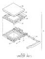
- FIG. 1 of the attached drawingsshows an example of the socket connectors that is referred to as ZIF (Zero Insertion Force) socket connector.
- the socket connectorgenerally designated with reference numeral 10 , comprises a housing 12 , made of an insulation material, defining an array of open cells 14 in which conductive terminals (not shown in FIG. 1) are received and a cover 16 movably supported on the housing 12 .
- the cover 16defines through holes 18 corresponding to the cells 14 of the housing 12 .
- the cover 16carries a CPU module 20 with pin legs 22 of the CPU module 20 extending through the holes 18 of the cover 16 and partially projecting into the cells 14 .
- An actuator 24drives the cover 16 to move in a predetermined direction A in such a manner to bring the pin legs 24 of the CPU module 20 into contact with the terminals of the housing 12 thereby forming electrical connection therebetween.
- Examples of socket connectors of this typeare also disclosed in U.S. Pat. Nos. 4,498,725, 5,833,483, 6,059,596, 6,142,8 10, and 6,159,032.
- a number of different terminals for the socket connectorsare available. They can be roughly classified as single-beam terminals and dual-beam terminals. Terminals of both types have a base section received and securely retained in the cell of the housing and a tail extending from the base and beyond a lower face of the housing for being soldered to the circuit board.
- a signal-beam terminalhas a single beam extending from base section substantially in a direction opposite to the tail and forming a spring arm on a free end of the beam, while a dual-beam terminal has two beams opposite to each other.
- An example of the dual beam-terminalis illustrated in U.S. Pat. No. 4,498,725 and shown is FIG. 2 of the attached drawings.
- the dual-beam terminalgenerally designated with reference numeral 30 in FIG.
- a base section 32comprises a base section 32 and a tail 34 extending from the base section 32 in a downward direction (as viewed in FIG. 2 ).
- Two beams 36extend from the base section 32 in an upward direction that is substantially opposite to the downward direction of the tail 34 .
- the beams 36are opposite to each other and spring arms 38 are formed on free ends thereof and extending in a horizontal direction substantially parallel to the predetermined direction A and normal to the upward and downward directions. Free ends 40 of the spring arms 38 are convergent to each other for reducing the space therebetween.
- the pin leg 22 of the CPU module 20 that engages with the spring arms 38 of the terminal 30is first inserted into the space between the spring arms 38 .
- the pin leg 22is driven into the reduced space between the free ends 40 of the spring arms 38 for forming electrical connection therebetween.
- the terminal 30is usually made by stamping a metal plate, followed by mechanically forming the beams 36 and the spring arms 38 .
- a major surface of each beam 36is made substantially parallel to an imaginary plane defined by the direction A and the upward direction whereby the pin leg 22 is guided in the direction A.
- Such a conventional designsuffers certain deficiencies.
- the gap size between the free ends 40 of the spring arms 38is difficult to adjust.
- Spring rate of the spring arms 38is also difficult to adjust and this in turn makes the normal force acting upon the pin leg 22 by the spring arms 38 difficult to adjust in order to achieve optimum electrical and mechanical engagement between the spring arms 38 and the pin leg 22 .
- Such deficienciesare even more severe in a housing having compactly arranged terminals for the terminal pitch is reduced. Reduced terminal pitch indicates the spring arms 38 must be shortened, leading to difficulty for adjustment of the above parameters.
- An object of the present inventionis to provide a dual-beam terminal of a socket connector that allows easy adjustment of contact gap between opposite spring arms thereof.
- Another object of the present inventionis to provide a dual-beam terminal of a socket connector that allows easy adjustment of spring rate and thus the normal force acting upon a pin leg engaging therewith.
- a further object of the present inventionis to provide a dual-beam terminal having a performance adjustable configuration of the beams.
- a socket connectorcomprises a housing positioned on a circuit board and movably supporting a cover.
- Cellsare defined in the housing for receiving and retaining dual-beam terminals.
- the covercarries a central processing unit module having pin legs extending through holes defined in the cover and partially projecting into the cells of the housing. The cover is movable in a moving direction to bring the pin legs into engagement with the corresponding terminals.
- Each dual-beam terminalcomprises a base section received and firmly retained in the corresponding cell and a tail extending from the base section and beyond the housing for being soldered to the circuit board. Two beams extend from the base section, substantially opposite to the tail. Each beam forms a spring arm on a free end thereof.
- the spring armsare opposite to and spaced from each other for engaging the corresponding pin leg therebetween.
- the beamsare symmetric with respect to an imaginary plane that is normal to the base section and coincident with the moving direction.
- Each beamhas a major surface angularly offset from the imaginary plane and thus forming a first included angle with the imaginary plane.
- the major surfacealso forms a second included angle with the base section.
- the included anglesare smaller than 90 degrees and greater than 0 degree. Preferably, the included angles are 45 degrees.
- the angularly offset configuration of the beamsallows easy adjustment of the space between the spring arms and thus adjustment of the performance parameters of the terminals.
- FIG. 1is an exploded view of a socket connector
- FIG. 2is a perspective view of a conventional conductive terminal that can be received and retained in a cell of the socket connector of FIG. 1;
- FIG. 3is a perspective view of a conductive terminal constructed in accordance with the present invention that can be received and retained in the cell of the socket connector of FIG. 1;
- FIG. 4is a front view of the conductive terminal of the present invention.
- FIG. 5is a side elevational view of the conductive terminal of the present invention.
- FIG. 6is a top view of the conductive terminal of the present invention.
- a conductive terminal constructed in accordance with the present inventionis to be received and retained in a cell 14 defined in a housing 12 of a socket connector 10 (FIG. 1 ).
- the terminal 100is made by stamping a metal plate and followed by subsequent forming operations.
- the terminal 100comprises a base section 102 having a first major surface (not labeled).
- the base section 102is received in the cell 14 and forms barbed edges 104 on opposite sides thereof for interferentially engaging the cell 14 to firmly retain the terminal 100 in the cell 14 .
- a tail section 106extends from a lower edge of the base section 102 .
- the tail section 106comprises a solder pad 108 connected to the lower edge of the base section 102 by a neck portion 109 .
- the neck portion 109is bent an angle of approximately 90 degrees whereby a second major surface of the solder pad 108 is substantially normal to the first major surface of the base section 102 .
- the solder pad 106can carry a solder ball (not shown) for connecting the terminal 100 to a circuit board (not shown) by Surface Mount Technology (SMT).
- SMTSurface Mount Technology
- An extension 110is formed on an upper edge of the base section 102 .
- Two beams 112extend from opposite edges of the extension 110 in an upward direction that is substantially parallel to the first major surface of the base section 102 .
- the beams 112are spaced from each other for accommodating movement of a pin leg 22 of an electronic device 20 (FIG. 1) in a predetermined moving direction A therebetween.
- the beams 112are made symmetric with respect to an imaginary central plane P (FIGS. 4 and 6) and the central plane P bisects the base section 102 and the terminal 100 itself. That is the terminal 100 is symmetric with respect to the central plane P and thus the moving direction A is coincident with the central plane P. However, it is not necessary to be so.
- Each beam 112has a third major surface angularly offset from the first major surface and the central plane P by a given angle.
- the third major surfaceforms an included angle B with the first major surface of the base section 102 and the third major surface also forms an included angle (not labeled) with respect to the central surface P.
- the angle Bis preferably 45 degrees.
- the third major surfacealso forms a 45 degree included angle with respect to the central plane P. It is, however, apparent to those having ordinary skills to adapt a different value of the included angle B.
- the included angle Bcan be any angle greater than 0 degree but smaller than 90 degrees.
- a spring arm 114has a proximal section 116 connected to a free end of each beam 112 by a connection section 118 and a distal section 120 extends from the proximal section 116 and away from the beam 112 in a direction substantially parallel to the moving direction A of the pin leg 22 and the central plane P.
- the spring arms 114are symmetrical with respect to the central plane P.
- the proximal sections 116 of the spring arms 114are spaced from each other and are arranged to convergent toward each other whereby the distance between the proximal sections 116 is reduced toward a minimum gap (not labeled) between the distal sections 120 .
- the distal sections 120are substantially parallel to each other and spaced from each other by the gap that corresponds the minimum distance between the proximal sections 116 .
- the convergent configuration of the proximal sections 116functions to lead the pin leg 22 of the electronic device 20 into the gap between the distal sections 120 .
- the gap between the distal sections 120is selected to have the distal sections 120 of the spring arms 114 firmly engage the pin leg 22 .
- the angularly offset beams 112allows flexibility in setting and adjusting performance parameters of the terminal 100 , such as the gap between the spring arms 114 and the spring rate of the beams 112 and the spring arms 114 experienced by the pin leg 22 .
- the distal sections 120are arranged in a convergent manner to serve as a lead-in of the pin leg 22 , while the proximal sections 116 are substantially parallel to each other as well as the moving direction A of the pin leg 22 (or the central plane P) and form a small gap therebetween for electrically and mechanically engaging the pin leg 22 .
- connection section 118are inclined toward the central plane P and thus convergent toward each other as they extend away from the beams 112 for reducing the distance between the spring arms 114 and also for more flexibility in setting and adjusting the performance parameters.
Landscapes
- Engineering & Computer Science (AREA)
- Microelectronics & Electronic Packaging (AREA)
- Coupling Device And Connection With Printed Circuit (AREA)
Abstract
Description
1. Field of the Invention
The present invention generally relates to a socket connector comprising conductive terminals for electrically connecting an electronic device, such as a central processing unit (CPU) module, to a circuit board, and more particular to the structure of the terminals.
2. The Related Arts
Socket connectors for mounting an electronic device, such as a central processing unit (CPU) module, to a circuit board are well known and are commonly used in the computer industry. FIG. 1 of the attached drawings shows an example of the socket connectors that is referred to as ZIF (Zero Insertion Force) socket connector. The socket connector, generally designated withreference numeral 10, comprises ahousing 12, made of an insulation material, defining an array ofopen cells 14 in which conductive terminals (not shown in FIG. 1) are received and acover 16 movably supported on thehousing 12. Thecover 16 defines throughholes 18 corresponding to thecells 14 of thehousing 12. Thecover 16 carries aCPU module 20 withpin legs 22 of theCPU module 20 extending through theholes 18 of thecover 16 and partially projecting into thecells 14. Anactuator 24 drives thecover 16 to move in a predetermined direction A in such a manner to bring thepin legs 24 of theCPU module 20 into contact with the terminals of thehousing 12 thereby forming electrical connection therebetween. Examples of socket connectors of this type are also disclosed in U.S. Pat. Nos. 4,498,725, 5,833,483, 6,059,596, 6,142,8 10, and 6,159,032.
A number of different terminals for the socket connectors are available. They can be roughly classified as single-beam terminals and dual-beam terminals. Terminals of both types have a base section received and securely retained in the cell of the housing and a tail extending from the base and beyond a lower face of the housing for being soldered to the circuit board. A signal-beam terminal has a single beam extending from base section substantially in a direction opposite to the tail and forming a spring arm on a free end of the beam, while a dual-beam terminal has two beams opposite to each other. An example of the dual beam-terminal is illustrated in U.S. Pat. No. 4,498,725 and shown is FIG. 2 of the attached drawings. The dual-beam terminal, generally designated withreference numeral 30 in FIG. 2, comprises abase section 32 and atail 34 extending from thebase section 32 in a downward direction (as viewed in FIG.2). Twobeams 36 extend from thebase section 32 in an upward direction that is substantially opposite to the downward direction of thetail 34. Thebeams 36 are opposite to each other andspring arms 38 are formed on free ends thereof and extending in a horizontal direction substantially parallel to the predetermined direction A and normal to the upward and downward directions.Free ends 40 of thespring arms 38 are convergent to each other for reducing the space therebetween.
Since thebeams 36 and thespring arms 38 are made substantially opposite to each other, forming a mirror symmetry configuration. Thepin leg 22 of theCPU module 20 that engages with thespring arms 38 of theterminal 30 is first inserted into the space between thespring arms 38. When thecover 16 moves in the direction A, thepin leg 22 is driven into the reduced space between thefree ends 40 of thespring arms 38 for forming electrical connection therebetween.
Theterminal 30 is usually made by stamping a metal plate, followed by mechanically forming thebeams 36 and thespring arms 38. Conventionally, a major surface of eachbeam 36 is made substantially parallel to an imaginary plane defined by the direction A and the upward direction whereby thepin leg 22 is guided in the direction A. Such a conventional design suffers certain deficiencies. For example, the gap size between thefree ends 40 of thespring arms 38 is difficult to adjust. Spring rate of thespring arms 38 is also difficult to adjust and this in turn makes the normal force acting upon thepin leg 22 by thespring arms 38 difficult to adjust in order to achieve optimum electrical and mechanical engagement between thespring arms 38 and thepin leg 22. Such deficiencies are even more severe in a housing having compactly arranged terminals for the terminal pitch is reduced. Reduced terminal pitch indicates thespring arms 38 must be shortened, leading to difficulty for adjustment of the above parameters.
Thus, it is desired to have a terminal configured to overcome the above mentioned deficiencies.
An object of the present invention is to provide a dual-beam terminal of a socket connector that allows easy adjustment of contact gap between opposite spring arms thereof.
Another object of the present invention is to provide a dual-beam terminal of a socket connector that allows easy adjustment of spring rate and thus the normal force acting upon a pin leg engaging therewith.
A further object of the present invention is to provide a dual-beam terminal having a performance adjustable configuration of the beams.
To achieve the above objects, in accordance with the present invention, a socket connector comprises a housing positioned on a circuit board and movably supporting a cover. Cells are defined in the housing for receiving and retaining dual-beam terminals. The cover carries a central processing unit module having pin legs extending through holes defined in the cover and partially projecting into the cells of the housing. The cover is movable in a moving direction to bring the pin legs into engagement with the corresponding terminals. Each dual-beam terminal comprises a base section received and firmly retained in the corresponding cell and a tail extending from the base section and beyond the housing for being soldered to the circuit board. Two beams extend from the base section, substantially opposite to the tail. Each beam forms a spring arm on a free end thereof. The spring arms are opposite to and spaced from each other for engaging the corresponding pin leg therebetween. The beams are symmetric with respect to an imaginary plane that is normal to the base section and coincident with the moving direction. Each beam has a major surface angularly offset from the imaginary plane and thus forming a first included angle with the imaginary plane. The major surface also forms a second included angle with the base section. The included angles are smaller than 90 degrees and greater than 0 degree. Preferably, the included angles are 45 degrees. The angularly offset configuration of the beams allows easy adjustment of the space between the spring arms and thus adjustment of the performance parameters of the terminals.
The present invention will be apparent to those skilled in the art by reading the following description of a preferred embodiment thereof, with reference to the attached drawings, in which:
FIG. 1 is an exploded view of a socket connector;
FIG. 2 is a perspective view of a conventional conductive terminal that can be received and retained in a cell of the socket connector of FIG. 1;
FIG. 3 is a perspective view of a conductive terminal constructed in accordance with the present invention that can be received and retained in the cell of the socket connector of FIG. 1;
FIG. 4 is a front view of the conductive terminal of the present invention;
FIG. 5 is a side elevational view of the conductive terminal of the present invention; and
FIG. 6 is a top view of the conductive terminal of the present invention.
With reference to the drawings and in particular to FIGS. 3-6, a conductive terminal constructed in accordance with the present invention, generally designated withreference numeral 100, is to be received and retained in acell 14 defined in ahousing 12 of a socket connector10 (FIG.1). Theterminal 100 is made by stamping a metal plate and followed by subsequent forming operations. Theterminal 100 comprises abase section 102 having a first major surface (not labeled). Thebase section 102 is received in thecell 14 and formsbarbed edges 104 on opposite sides thereof for interferentially engaging thecell 14 to firmly retain theterminal 100 in thecell 14. Atail section 106 extends from a lower edge of thebase section 102. Thetail section 106 comprises asolder pad 108 connected to the lower edge of thebase section 102 by aneck portion 109. Theneck portion 109 is bent an angle of approximately 90 degrees whereby a second major surface of thesolder pad 108 is substantially normal to the first major surface of thebase section 102.
Thesolder pad 106 can carry a solder ball (not shown) for connecting the terminal100 to a circuit board (not shown) by Surface Mount Technology (SMT). However, it is apparent to those having ordinary skills to form a tail configured to employ the “through-hole” technique for connecting the terminal100 to the circuit board. This is well known and no further description is necessary herein.
Anextension 110 is formed on an upper edge of thebase section 102. Twobeams 112 extend from opposite edges of theextension 110 in an upward direction that is substantially parallel to the first major surface of thebase section 102. Thebeams 112 are spaced from each other for accommodating movement of apin leg 22 of an electronic device20 (FIG. 1) in a predetermined moving direction A therebetween. In the embodiment illustrated, thebeams 112 are made symmetric with respect to an imaginary central plane P (FIGS. 4 and 6) and the central plane P bisects thebase section 102 and the terminal100 itself. That is the terminal100 is symmetric with respect to the central plane P and thus the moving direction A is coincident with the central plane P. However, it is not necessary to be so.
Eachbeam 112 has a third major surface angularly offset from the first major surface and the central plane P by a given angle. Namely, the third major surface forms an included angle B with the first major surface of thebase section 102 and the third major surface also forms an included angle (not labeled) with respect to the central surface P. The angle B is preferably 45 degrees. In other words, the third major surface also forms a 45 degree included angle with respect to the central plane P. It is, however, apparent to those having ordinary skills to adapt a different value of the included angle B. The included angle B can be any angle greater than 0 degree but smaller than 90 degrees.
Aspring arm 114 has aproximal section 116 connected to a free end of eachbeam 112 by aconnection section 118 and adistal section 120 extends from theproximal section 116 and away from thebeam 112 in a direction substantially parallel to the moving direction A of thepin leg 22 and the central plane P. Thespring arms 114 are symmetrical with respect to the central plane P.
Theproximal sections 116 of thespring arms 114 are spaced from each other and are arranged to convergent toward each other whereby the distance between theproximal sections 116 is reduced toward a minimum gap (not labeled) between thedistal sections 120. Thedistal sections 120 are substantially parallel to each other and spaced from each other by the gap that corresponds the minimum distance between theproximal sections 116. The convergent configuration of theproximal sections 116 functions to lead thepin leg 22 of theelectronic device 20 into the gap between thedistal sections 120. The gap between thedistal sections 120 is selected to have thedistal sections 120 of thespring arms 114 firmly engage thepin leg 22. The angularly offsetbeams 112 allows flexibility in setting and adjusting performance parameters of the terminal100, such as the gap between thespring arms 114 and the spring rate of thebeams 112 and thespring arms 114 experienced by thepin leg 22.
It is, however, apparent to those skilled in the art to switch the functions of thedistal sections 120 and theproximal sections 116. Namely, thedistal sections 120 are arranged in a convergent manner to serve as a lead-in of thepin leg 22, while theproximal sections 116 are substantially parallel to each other as well as the moving direction A of the pin leg22 (or the central plane P) and form a small gap therebetween for electrically and mechanically engaging thepin leg 22.
In the embodiment illustrated, theconnection section 118 are inclined toward the central plane P and thus convergent toward each other as they extend away from thebeams 112 for reducing the distance between thespring arms 114 and also for more flexibility in setting and adjusting the performance parameters.
Although the present invention has been described with reference to the preferred embodiment thereof, it is apparent to those skilled in the art that a variety of modifications and changes may be made without departing from the scope of the present invention which is intended to be defined by the appended claims.
Claims (5)
1. A conductive terminal comprising:
a base section adapted to be received and firmly retained in a cell defined in a housing, the base section having a first major surface;
two beams extending from a first edge of the base section and symmetric with respect to an imaginary plane, each beam having a major surface angularly offset with respect to the imaginary plane by an angle; and
a tail extending from a second edge of the base section and opposite to the beams;
wherein each beam forms a spring arm, the spring arms being symmetrical with respect to the imaginary plane, each spring arm comprising a lead-in section and an engaging section, the lead-in sections being convergent toward the imaginary plane with a distance between the lead-in sections gradually reduced to a minimum gap between the engaging sections;
wherein each spring arm is connected to the corresponding beam by an inclined connection section;
wherein the inclined connection section connects the engaging section of each spring arm to a free end of the corresponding beam;
wherein the tail comprises a solder pad connected to the second edge of the base section by a neck portion whereby the solder pad is substantially normal to the first major surface of the base section;
wherein the base section forms barbed side edges for interferentially engaging the cell.
2. The conductive terminal as claimed inclaim 1 , wherein the offset angle is around 45 degrees.
3. A socket connector adapted to mount an electronic device having pin legs to a circuit board, the socket connector comprising:
a housing defining cells therein;
a cover movably supported on the housing and defining through holes corresponding to the cells, the cover being adapted to carry the electronic device with the pin legs extending through the holes of the cover and partially extending into the cells of the housing and move the electronic device and the pin legs in a given moving direction with respect to the housing; and
a conductive terminal comprising:
a base section received and fixed in each cell of the housing;
two beams extending from a first edge of the base section toward the cover, each beam forming a spring arm, the spring arms being located on opposite sides of an imaginary plane parallel to the moving direction, and spaced from each other for accommodating the movement of the pin leg therebetween, each spring arm comprising a lead-in section and an engaging section, the lead-in sections being convergent toward the imaginary plane with a distance between the lead-in sections gradually reduced to a minimum gap between the engaging sections where the pin leg engages the spring arms; and
a tail extending from a second edge of the base section and opposite to the beams, the tail being adapted to be soldered to the circuit board;
wherein each beam has a major surface angularly offset with respect to the imaginary plane by an angle;
wherein each spring arm is connected to the corresponding beam by an inclined connection section;
wherein the inclined connection section connects the engaging section of each spring arm to a free end of the corresponding beam;
wherein the tail comprises a solder pad connected to the second edge of the base section by a neck portion whereby the solder pad is substantially normal to the base section;
wherein the offset angle is smaller than 90 degrees and greater than 0 degree;
wherein the spring arms are symmetric with respect to the imaginary plane;
wherein the base section has a major surface substantially normal to the imaginary plane and wherein the imaginary plane bisects the base section whereby the terminal is substantially symmetric with respect to the imaginary plane.
4. The socket connector as claimed inclaim 3 , wherein the base section forms barbed side edges for interferentially engaging the cell of the housing.
5. The socket connector as claimed inclaim 3 , wherein the offset angle is around 45 degrees.
Priority Applications (2)
| Application Number | Priority Date | Filing Date | Title |
|---|---|---|---|
| US10/035,576US6461183B1 (en) | 2001-12-27 | 2001-12-27 | Terminal of socket connector |
| US10/267,347US6558182B1 (en) | 2001-12-27 | 2002-10-08 | Terminal of socket connector |
Applications Claiming Priority (1)
| Application Number | Priority Date | Filing Date | Title |
|---|---|---|---|
| US10/035,576US6461183B1 (en) | 2001-12-27 | 2001-12-27 | Terminal of socket connector |
Related Child Applications (1)
| Application Number | Title | Priority Date | Filing Date |
|---|---|---|---|
| US10/267,347ContinuationUS6558182B1 (en) | 2001-12-27 | 2002-10-08 | Terminal of socket connector |
Publications (1)
| Publication Number | Publication Date |
|---|---|
| US6461183B1true US6461183B1 (en) | 2002-10-08 |
Family
ID=21883527
Family Applications (2)
| Application Number | Title | Priority Date | Filing Date |
|---|---|---|---|
| US10/035,576Expired - Fee RelatedUS6461183B1 (en) | 2001-12-27 | 2001-12-27 | Terminal of socket connector |
| US10/267,347Expired - Fee RelatedUS6558182B1 (en) | 2001-12-27 | 2002-10-08 | Terminal of socket connector |
Family Applications After (1)
| Application Number | Title | Priority Date | Filing Date |
|---|---|---|---|
| US10/267,347Expired - Fee RelatedUS6558182B1 (en) | 2001-12-27 | 2002-10-08 | Terminal of socket connector |
Country Status (1)
| Country | Link |
|---|---|
| US (2) | US6461183B1 (en) |
Cited By (80)
| Publication number | Priority date | Publication date | Assignee | Title |
|---|---|---|---|---|
| US6561831B1 (en)* | 2001-12-27 | 2003-05-13 | Hon Hai Precision Ind. Co., Ltd. | Housing of socket connector and conductive terminal thereof |
| US20030092304A1 (en)* | 2001-11-13 | 2003-05-15 | Whyne Richard Nicholas | Zero insertion force socket terminal |
| US6634911B1 (en)* | 2002-06-07 | 2003-10-21 | Hon Hai Precision Ind. Co., Ltd. | Contact for electrical connector |
| US20040102106A1 (en)* | 2002-11-22 | 2004-05-27 | Masao Okita | Electrical contact with arcuate contact portion |
| US6955545B1 (en)* | 2004-04-27 | 2005-10-18 | Tyco Electronics Corporation | Two piece ball grid array |
| WO2005112532A1 (en)* | 2004-05-10 | 2005-11-24 | Molex Incorporated | Socket connector terminal |
| US20060105598A1 (en)* | 2003-01-29 | 2006-05-18 | Molex Incorporated | Conductive terminal and the electrical connector using the conductive terminal |
| US20070059966A1 (en)* | 2005-09-12 | 2007-03-15 | Hon Hai Precision Ind. Co., Ltd. | Terminals for electrical connector |
| CN100429831C (en)* | 2003-04-03 | 2008-10-29 | 富士康(昆山)电脑接插件有限公司 | Electric connector compount |
| US20090088028A1 (en)* | 2007-10-01 | 2009-04-02 | Fci Americas Technology, Inc. | Power connectors with contact-retention features |
| US7541135B2 (en)* | 2005-04-05 | 2009-06-02 | Fci Americas Technology, Inc. | Power contact having conductive plates with curved portions contact beams and board tails |
| US7641500B2 (en) | 2007-04-04 | 2010-01-05 | Fci Americas Technology, Inc. | Power cable connector system |
| US20100015861A1 (en)* | 2008-07-21 | 2010-01-21 | Hon Hai Precision Industry Co., Ltd. | Contact having lead-in arrangement in body portion facilitating smooth and reliable insertion |
| US7690937B2 (en) | 2003-12-31 | 2010-04-06 | Fci Americas Technology, Inc. | Electrical power contacts and connectors comprising same |
| USRE41283E1 (en) | 2003-01-28 | 2010-04-27 | Fci Americas Technology, Inc. | Power connector with safety feature |
| US7726982B2 (en) | 2006-06-15 | 2010-06-01 | Fci Americas Technology, Inc. | Electrical connectors with air-circulation features |
| USD618181S1 (en) | 2009-04-03 | 2010-06-22 | Fci Americas Technology, Inc. | Asymmetrical electrical connector |
| USD618180S1 (en) | 2009-04-03 | 2010-06-22 | Fci Americas Technology, Inc. | Asymmetrical electrical connector |
| US7749009B2 (en) | 2005-01-31 | 2010-07-06 | Fci Americas Technology, Inc. | Surface-mount connector |
| USD619099S1 (en) | 2009-01-30 | 2010-07-06 | Fci Americas Technology, Inc. | Electrical connector |
| US7905731B2 (en) | 2007-05-21 | 2011-03-15 | Fci Americas Technology, Inc. | Electrical connector with stress-distribution features |
| US8062051B2 (en) | 2008-07-29 | 2011-11-22 | Fci Americas Technology Llc | Electrical communication system having latching and strain relief features |
| FR2971891A1 (en)* | 2011-02-22 | 2012-08-24 | Radiall Sa | ELECTRIC CONTACT FOR CONNECTOR |
| US8323049B2 (en) | 2009-01-30 | 2012-12-04 | Fci Americas Technology Llc | Electrical connector having power contacts |
| US8525346B2 (en) | 2009-06-02 | 2013-09-03 | Hsio Technologies, Llc | Compliant conductive nano-particle electrical interconnect |
| US8610265B2 (en) | 2009-06-02 | 2013-12-17 | Hsio Technologies, Llc | Compliant core peripheral lead semiconductor test socket |
| US8618649B2 (en) | 2009-06-02 | 2013-12-31 | Hsio Technologies, Llc | Compliant printed circuit semiconductor package |
| US20140038446A1 (en)* | 2012-08-06 | 2014-02-06 | Shenzhen China Star Optoelectronics Technology Co., Ltd. | Spring plate type connector for use in backlight module |
| US8758067B2 (en) | 2010-06-03 | 2014-06-24 | Hsio Technologies, Llc | Selective metalization of electrical connector or socket housing |
| US8789272B2 (en) | 2009-06-02 | 2014-07-29 | Hsio Technologies, Llc | Method of making a compliant printed circuit peripheral lead semiconductor test socket |
| US8803539B2 (en) | 2009-06-03 | 2014-08-12 | Hsio Technologies, Llc | Compliant wafer level probe assembly |
| USD718253S1 (en) | 2012-04-13 | 2014-11-25 | Fci Americas Technology Llc | Electrical cable connector |
| US8905651B2 (en) | 2012-01-31 | 2014-12-09 | Fci | Dismountable optical coupling device |
| US8912812B2 (en) | 2009-06-02 | 2014-12-16 | Hsio Technologies, Llc | Compliant printed circuit wafer probe diagnostic tool |
| USD720698S1 (en) | 2013-03-15 | 2015-01-06 | Fci Americas Technology Llc | Electrical cable connector |
| US8928344B2 (en) | 2009-06-02 | 2015-01-06 | Hsio Technologies, Llc | Compliant printed circuit socket diagnostic tool |
| US8944831B2 (en) | 2012-04-13 | 2015-02-03 | Fci Americas Technology Llc | Electrical connector having ribbed ground plate with engagement members |
| US8955216B2 (en) | 2009-06-02 | 2015-02-17 | Hsio Technologies, Llc | Method of making a compliant printed circuit peripheral lead semiconductor package |
| US8955215B2 (en) | 2009-05-28 | 2015-02-17 | Hsio Technologies, Llc | High performance surface mount electrical interconnect |
| US8970031B2 (en) | 2009-06-16 | 2015-03-03 | Hsio Technologies, Llc | Semiconductor die terminal |
| US8981568B2 (en) | 2009-06-16 | 2015-03-17 | Hsio Technologies, Llc | Simulated wirebond semiconductor package |
| US8981809B2 (en) | 2009-06-29 | 2015-03-17 | Hsio Technologies, Llc | Compliant printed circuit semiconductor tester interface |
| US8988093B2 (en) | 2009-06-02 | 2015-03-24 | Hsio Technologies, Llc | Bumped semiconductor wafer or die level electrical interconnect |
| US8984748B2 (en) | 2009-06-29 | 2015-03-24 | Hsio Technologies, Llc | Singulated semiconductor device separable electrical interconnect |
| US8987886B2 (en) | 2009-06-02 | 2015-03-24 | Hsio Technologies, Llc | Copper pillar full metal via electrical circuit structure |
| USD727268S1 (en) | 2012-04-13 | 2015-04-21 | Fci Americas Technology Llc | Vertical electrical connector |
| USD727852S1 (en) | 2012-04-13 | 2015-04-28 | Fci Americas Technology Llc | Ground shield for a right angle electrical connector |
| US9048583B2 (en) | 2009-03-19 | 2015-06-02 | Fci Americas Technology Llc | Electrical connector having ribbed ground plate |
| US9054097B2 (en) | 2009-06-02 | 2015-06-09 | Hsio Technologies, Llc | Compliant printed circuit area array semiconductor device package |
| USD733662S1 (en) | 2013-01-25 | 2015-07-07 | Fci Americas Technology Llc | Connector housing for electrical connector |
| US9093767B2 (en) | 2009-06-02 | 2015-07-28 | Hsio Technologies, Llc | High performance surface mount electrical interconnect |
| US9136196B2 (en) | 2009-06-02 | 2015-09-15 | Hsio Technologies, Llc | Compliant printed circuit wafer level semiconductor package |
| US9184527B2 (en) | 2009-06-02 | 2015-11-10 | Hsio Technologies, Llc | Electrical connector insulator housing |
| US9184145B2 (en) | 2009-06-02 | 2015-11-10 | Hsio Technologies, Llc | Semiconductor device package adapter |
| US9196980B2 (en) | 2009-06-02 | 2015-11-24 | Hsio Technologies, Llc | High performance surface mount electrical interconnect with external biased normal force loading |
| USD746236S1 (en) | 2012-07-11 | 2015-12-29 | Fci Americas Technology Llc | Electrical connector housing |
| US9231328B2 (en) | 2009-06-02 | 2016-01-05 | Hsio Technologies, Llc | Resilient conductive electrical interconnect |
| US9232654B2 (en) | 2009-06-02 | 2016-01-05 | Hsio Technologies, Llc | High performance electrical circuit structure |
| US9257778B2 (en) | 2012-04-13 | 2016-02-09 | Fci Americas Technology | High speed electrical connector |
| US9276339B2 (en) | 2009-06-02 | 2016-03-01 | Hsio Technologies, Llc | Electrical interconnect IC device socket |
| US9277654B2 (en) | 2009-06-02 | 2016-03-01 | Hsio Technologies, Llc | Composite polymer-metal electrical contacts |
| US9276336B2 (en) | 2009-05-28 | 2016-03-01 | Hsio Technologies, Llc | Metalized pad to electrical contact interface |
| US9318862B2 (en) | 2009-06-02 | 2016-04-19 | Hsio Technologies, Llc | Method of making an electronic interconnect |
| US9320133B2 (en) | 2009-06-02 | 2016-04-19 | Hsio Technologies, Llc | Electrical interconnect IC device socket |
| US9320144B2 (en) | 2009-06-17 | 2016-04-19 | Hsio Technologies, Llc | Method of forming a semiconductor socket |
| US9350093B2 (en) | 2010-06-03 | 2016-05-24 | Hsio Technologies, Llc | Selective metalization of electrical connector or socket housing |
| US9414500B2 (en) | 2009-06-02 | 2016-08-09 | Hsio Technologies, Llc | Compliant printed flexible circuit |
| US9536815B2 (en) | 2009-05-28 | 2017-01-03 | Hsio Technologies, Llc | Semiconductor socket with direct selective metalization |
| US9543703B2 (en) | 2012-07-11 | 2017-01-10 | Fci Americas Technology Llc | Electrical connector with reduced stack height |
| US9559447B2 (en) | 2015-03-18 | 2017-01-31 | Hsio Technologies, Llc | Mechanical contact retention within an electrical connector |
| US9603249B2 (en) | 2009-06-02 | 2017-03-21 | Hsio Technologies, Llc | Direct metalization of electrical circuit structures |
| US9613841B2 (en) | 2009-06-02 | 2017-04-04 | Hsio Technologies, Llc | Area array semiconductor device package interconnect structure with optional package-to-package or flexible circuit to package connection |
| US20170133781A1 (en)* | 2015-11-10 | 2017-05-11 | Advanced-Connectek Inc. | Plug terminal |
| US9689897B2 (en) | 2010-06-03 | 2017-06-27 | Hsio Technologies, Llc | Performance enhanced semiconductor socket |
| US9699906B2 (en) | 2009-06-02 | 2017-07-04 | Hsio Technologies, Llc | Hybrid printed circuit assembly with low density main core and embedded high density circuit regions |
| US9761520B2 (en) | 2012-07-10 | 2017-09-12 | Hsio Technologies, Llc | Method of making an electrical connector having electrodeposited terminals |
| US9930775B2 (en) | 2009-06-02 | 2018-03-27 | Hsio Technologies, Llc | Copper pillar full metal via electrical circuit structure |
| US10159154B2 (en) | 2010-06-03 | 2018-12-18 | Hsio Technologies, Llc | Fusion bonded liquid crystal polymer circuit structure |
| US10506722B2 (en) | 2013-07-11 | 2019-12-10 | Hsio Technologies, Llc | Fusion bonded liquid crystal polymer electrical circuit structure |
| US10667410B2 (en) | 2013-07-11 | 2020-05-26 | Hsio Technologies, Llc | Method of making a fusion bonded circuit structure |
Families Citing this family (7)
| Publication number | Priority date | Publication date | Assignee | Title |
|---|---|---|---|---|
| US6743037B2 (en)* | 2002-04-24 | 2004-06-01 | Intel Corporation | Surface mount socket contact providing uniform solder ball loading and method |
| CN2598181Y (en)* | 2003-01-29 | 2004-01-07 | 莫列斯公司 | Conducting terminal and electric connector using same |
| US6960092B1 (en)* | 2003-07-25 | 2005-11-01 | Advanced Micro Devices, Inc. | Compression mount and zero insertion force socket for IC devices |
| TWM253132U (en)* | 2003-10-31 | 2004-12-11 | Hon Hai Prec Ind Co Ltd | Electrical connector |
| TWM254771U (en)* | 2003-12-12 | 2005-01-01 | Top Yang Technology Entpr Co | Terminal structure of electrical connector with zero insertion force |
| CN210111103U (en)* | 2019-03-22 | 2020-02-21 | 富顶精密组件(深圳)有限公司 | Electric connector and conductive terminal thereof |
| US20230178292A1 (en)* | 2020-06-19 | 2023-06-08 | Murata Manufacturing Co., Ltd. | Edge-fit pins |
Citations (3)
| Publication number | Priority date | Publication date | Assignee | Title |
|---|---|---|---|---|
| US4534611A (en)* | 1981-06-23 | 1985-08-13 | Siemens Aktiengesellschaft | Contact springs |
| US5213530A (en)* | 1990-07-13 | 1993-05-25 | Yamaichi Electric Co., Ltd. | Three-way nip contact type contractor |
| US6142810A (en)* | 1999-03-02 | 2000-11-07 | Hon Hai Precision Ind. Co., Ltd. | ZIF socket terminal |
Family Cites Families (1)
| Publication number | Priority date | Publication date | Assignee | Title |
|---|---|---|---|---|
| US6478637B1 (en)* | 2001-12-24 | 2002-11-12 | Hon Hai Precision Ind. Co., Ltd. | Contact for CPU socket |
- 2001
- 2001-12-27USUS10/035,576patent/US6461183B1/ennot_activeExpired - Fee Related
- 2002
- 2002-10-08USUS10/267,347patent/US6558182B1/ennot_activeExpired - Fee Related
Patent Citations (3)
| Publication number | Priority date | Publication date | Assignee | Title |
|---|---|---|---|---|
| US4534611A (en)* | 1981-06-23 | 1985-08-13 | Siemens Aktiengesellschaft | Contact springs |
| US5213530A (en)* | 1990-07-13 | 1993-05-25 | Yamaichi Electric Co., Ltd. | Three-way nip contact type contractor |
| US6142810A (en)* | 1999-03-02 | 2000-11-07 | Hon Hai Precision Ind. Co., Ltd. | ZIF socket terminal |
Cited By (116)
| Publication number | Priority date | Publication date | Assignee | Title |
|---|---|---|---|---|
| US20030092304A1 (en)* | 2001-11-13 | 2003-05-15 | Whyne Richard Nicholas | Zero insertion force socket terminal |
| US6824414B2 (en)* | 2001-11-13 | 2004-11-30 | Tyco Electronics Corporation | Zero insertion force socket terminal |
| US6561831B1 (en)* | 2001-12-27 | 2003-05-13 | Hon Hai Precision Ind. Co., Ltd. | Housing of socket connector and conductive terminal thereof |
| US6634911B1 (en)* | 2002-06-07 | 2003-10-21 | Hon Hai Precision Ind. Co., Ltd. | Contact for electrical connector |
| US20040102106A1 (en)* | 2002-11-22 | 2004-05-27 | Masao Okita | Electrical contact with arcuate contact portion |
| US6830471B2 (en)* | 2002-11-22 | 2004-12-14 | Hon Hai Precision Ind. Co., Ltd. | Electrical contact with arcuate contact portion |
| USRE41283E1 (en) | 2003-01-28 | 2010-04-27 | Fci Americas Technology, Inc. | Power connector with safety feature |
| US7052289B1 (en)* | 2003-01-29 | 2006-05-30 | Molex Incorporated | Conductive terminal and the electrical connector using the conductive terminal |
| US20060105598A1 (en)* | 2003-01-29 | 2006-05-18 | Molex Incorporated | Conductive terminal and the electrical connector using the conductive terminal |
| CN100429831C (en)* | 2003-04-03 | 2008-10-29 | 富士康(昆山)电脑接插件有限公司 | Electric connector compount |
| US8187017B2 (en) | 2003-12-31 | 2012-05-29 | Fci Americas Technology Llc | Electrical power contacts and connectors comprising same |
| US7862359B2 (en) | 2003-12-31 | 2011-01-04 | Fci Americas Technology Llc | Electrical power contacts and connectors comprising same |
| US7690937B2 (en) | 2003-12-31 | 2010-04-06 | Fci Americas Technology, Inc. | Electrical power contacts and connectors comprising same |
| US8062046B2 (en) | 2003-12-31 | 2011-11-22 | Fci Americas Technology Llc | Electrical power contacts and connectors comprising same |
| US20050239304A1 (en)* | 2004-04-27 | 2005-10-27 | Morana Francis P | Two piece ball grid array |
| US6955545B1 (en)* | 2004-04-27 | 2005-10-18 | Tyco Electronics Corporation | Two piece ball grid array |
| WO2005112532A1 (en)* | 2004-05-10 | 2005-11-24 | Molex Incorporated | Socket connector terminal |
| US7749009B2 (en) | 2005-01-31 | 2010-07-06 | Fci Americas Technology, Inc. | Surface-mount connector |
| US7541135B2 (en)* | 2005-04-05 | 2009-06-02 | Fci Americas Technology, Inc. | Power contact having conductive plates with curved portions contact beams and board tails |
| US7303421B2 (en)* | 2005-09-12 | 2007-12-04 | Hon Hai Precision Ind. Co., Ltd. | Terminals for electrical connector |
| US20070059966A1 (en)* | 2005-09-12 | 2007-03-15 | Hon Hai Precision Ind. Co., Ltd. | Terminals for electrical connector |
| US7726982B2 (en) | 2006-06-15 | 2010-06-01 | Fci Americas Technology, Inc. | Electrical connectors with air-circulation features |
| US7641500B2 (en) | 2007-04-04 | 2010-01-05 | Fci Americas Technology, Inc. | Power cable connector system |
| US7905731B2 (en) | 2007-05-21 | 2011-03-15 | Fci Americas Technology, Inc. | Electrical connector with stress-distribution features |
| US20090088028A1 (en)* | 2007-10-01 | 2009-04-02 | Fci Americas Technology, Inc. | Power connectors with contact-retention features |
| US7762857B2 (en) | 2007-10-01 | 2010-07-27 | Fci Americas Technology, Inc. | Power connectors with contact-retention features |
| US7862364B2 (en) | 2008-07-21 | 2011-01-04 | Hon Hai Precision Ind. Co., Ltd. | Contact having lead-in arrangement in body portion facilitating smooth and reliable insertion |
| US20100015861A1 (en)* | 2008-07-21 | 2010-01-21 | Hon Hai Precision Industry Co., Ltd. | Contact having lead-in arrangement in body portion facilitating smooth and reliable insertion |
| US8062051B2 (en) | 2008-07-29 | 2011-11-22 | Fci Americas Technology Llc | Electrical communication system having latching and strain relief features |
| USD619099S1 (en) | 2009-01-30 | 2010-07-06 | Fci Americas Technology, Inc. | Electrical connector |
| US8323049B2 (en) | 2009-01-30 | 2012-12-04 | Fci Americas Technology Llc | Electrical connector having power contacts |
| US10720721B2 (en) | 2009-03-19 | 2020-07-21 | Fci Usa Llc | Electrical connector having ribbed ground plate |
| US10096921B2 (en) | 2009-03-19 | 2018-10-09 | Fci Usa Llc | Electrical connector having ribbed ground plate |
| US9461410B2 (en) | 2009-03-19 | 2016-10-04 | Fci Americas Technology Llc | Electrical connector having ribbed ground plate |
| US9048583B2 (en) | 2009-03-19 | 2015-06-02 | Fci Americas Technology Llc | Electrical connector having ribbed ground plate |
| USD653621S1 (en) | 2009-04-03 | 2012-02-07 | Fci Americas Technology Llc | Asymmetrical electrical connector |
| USD618180S1 (en) | 2009-04-03 | 2010-06-22 | Fci Americas Technology, Inc. | Asymmetrical electrical connector |
| USD618181S1 (en) | 2009-04-03 | 2010-06-22 | Fci Americas Technology, Inc. | Asymmetrical electrical connector |
| US8955215B2 (en) | 2009-05-28 | 2015-02-17 | Hsio Technologies, Llc | High performance surface mount electrical interconnect |
| US9660368B2 (en) | 2009-05-28 | 2017-05-23 | Hsio Technologies, Llc | High performance surface mount electrical interconnect |
| US9536815B2 (en) | 2009-05-28 | 2017-01-03 | Hsio Technologies, Llc | Semiconductor socket with direct selective metalization |
| US9276336B2 (en) | 2009-05-28 | 2016-03-01 | Hsio Technologies, Llc | Metalized pad to electrical contact interface |
| US8987886B2 (en) | 2009-06-02 | 2015-03-24 | Hsio Technologies, Llc | Copper pillar full metal via electrical circuit structure |
| US8525346B2 (en) | 2009-06-02 | 2013-09-03 | Hsio Technologies, Llc | Compliant conductive nano-particle electrical interconnect |
| US8829671B2 (en) | 2009-06-02 | 2014-09-09 | Hsio Technologies, Llc | Compliant core peripheral lead semiconductor socket |
| US10609819B2 (en) | 2009-06-02 | 2020-03-31 | Hsio Technologies, Llc | Hybrid printed circuit assembly with low density main core and embedded high density circuit regions |
| US9930775B2 (en) | 2009-06-02 | 2018-03-27 | Hsio Technologies, Llc | Copper pillar full metal via electrical circuit structure |
| US8912812B2 (en) | 2009-06-02 | 2014-12-16 | Hsio Technologies, Llc | Compliant printed circuit wafer probe diagnostic tool |
| US9699906B2 (en) | 2009-06-02 | 2017-07-04 | Hsio Technologies, Llc | Hybrid printed circuit assembly with low density main core and embedded high density circuit regions |
| US9613841B2 (en) | 2009-06-02 | 2017-04-04 | Hsio Technologies, Llc | Area array semiconductor device package interconnect structure with optional package-to-package or flexible circuit to package connection |
| US8928344B2 (en) | 2009-06-02 | 2015-01-06 | Hsio Technologies, Llc | Compliant printed circuit socket diagnostic tool |
| US9603249B2 (en) | 2009-06-02 | 2017-03-21 | Hsio Technologies, Llc | Direct metalization of electrical circuit structures |
| US8955216B2 (en) | 2009-06-02 | 2015-02-17 | Hsio Technologies, Llc | Method of making a compliant printed circuit peripheral lead semiconductor package |
| US8789272B2 (en) | 2009-06-02 | 2014-07-29 | Hsio Technologies, Llc | Method of making a compliant printed circuit peripheral lead semiconductor test socket |
| US8610265B2 (en) | 2009-06-02 | 2013-12-17 | Hsio Technologies, Llc | Compliant core peripheral lead semiconductor test socket |
| US8618649B2 (en) | 2009-06-02 | 2013-12-31 | Hsio Technologies, Llc | Compliant printed circuit semiconductor package |
| US9414500B2 (en) | 2009-06-02 | 2016-08-09 | Hsio Technologies, Llc | Compliant printed flexible circuit |
| US8988093B2 (en) | 2009-06-02 | 2015-03-24 | Hsio Technologies, Llc | Bumped semiconductor wafer or die level electrical interconnect |
| US9320133B2 (en) | 2009-06-02 | 2016-04-19 | Hsio Technologies, Llc | Electrical interconnect IC device socket |
| US9318862B2 (en) | 2009-06-02 | 2016-04-19 | Hsio Technologies, Llc | Method of making an electronic interconnect |
| US9277654B2 (en) | 2009-06-02 | 2016-03-01 | Hsio Technologies, Llc | Composite polymer-metal electrical contacts |
| US9276339B2 (en) | 2009-06-02 | 2016-03-01 | Hsio Technologies, Llc | Electrical interconnect IC device socket |
| US8704377B2 (en) | 2009-06-02 | 2014-04-22 | Hsio Technologies, Llc | Compliant conductive nano-particle electrical interconnect |
| US9054097B2 (en) | 2009-06-02 | 2015-06-09 | Hsio Technologies, Llc | Compliant printed circuit area array semiconductor device package |
| US9076884B2 (en) | 2009-06-02 | 2015-07-07 | Hsio Technologies, Llc | Compliant printed circuit semiconductor package |
| US9232654B2 (en) | 2009-06-02 | 2016-01-05 | Hsio Technologies, Llc | High performance electrical circuit structure |
| US9093767B2 (en) | 2009-06-02 | 2015-07-28 | Hsio Technologies, Llc | High performance surface mount electrical interconnect |
| US9136196B2 (en) | 2009-06-02 | 2015-09-15 | Hsio Technologies, Llc | Compliant printed circuit wafer level semiconductor package |
| US9184527B2 (en) | 2009-06-02 | 2015-11-10 | Hsio Technologies, Llc | Electrical connector insulator housing |
| US9184145B2 (en) | 2009-06-02 | 2015-11-10 | Hsio Technologies, Llc | Semiconductor device package adapter |
| US9196980B2 (en) | 2009-06-02 | 2015-11-24 | Hsio Technologies, Llc | High performance surface mount electrical interconnect with external biased normal force loading |
| US9231328B2 (en) | 2009-06-02 | 2016-01-05 | Hsio Technologies, Llc | Resilient conductive electrical interconnect |
| US8803539B2 (en) | 2009-06-03 | 2014-08-12 | Hsio Technologies, Llc | Compliant wafer level probe assembly |
| US8981568B2 (en) | 2009-06-16 | 2015-03-17 | Hsio Technologies, Llc | Simulated wirebond semiconductor package |
| US8970031B2 (en) | 2009-06-16 | 2015-03-03 | Hsio Technologies, Llc | Semiconductor die terminal |
| US9320144B2 (en) | 2009-06-17 | 2016-04-19 | Hsio Technologies, Llc | Method of forming a semiconductor socket |
| US8981809B2 (en) | 2009-06-29 | 2015-03-17 | Hsio Technologies, Llc | Compliant printed circuit semiconductor tester interface |
| US8984748B2 (en) | 2009-06-29 | 2015-03-24 | Hsio Technologies, Llc | Singulated semiconductor device separable electrical interconnect |
| US9689897B2 (en) | 2010-06-03 | 2017-06-27 | Hsio Technologies, Llc | Performance enhanced semiconductor socket |
| US10159154B2 (en) | 2010-06-03 | 2018-12-18 | Hsio Technologies, Llc | Fusion bonded liquid crystal polymer circuit structure |
| US9350093B2 (en) | 2010-06-03 | 2016-05-24 | Hsio Technologies, Llc | Selective metalization of electrical connector or socket housing |
| US8758067B2 (en) | 2010-06-03 | 2014-06-24 | Hsio Technologies, Llc | Selective metalization of electrical connector or socket housing |
| US9350124B2 (en) | 2010-12-01 | 2016-05-24 | Hsio Technologies, Llc | High speed circuit assembly with integral terminal and mating bias loading electrical connector assembly |
| EP2493027A1 (en) | 2011-02-22 | 2012-08-29 | Radiall | Electrical contact for an electrical connector |
| FR2971891A1 (en)* | 2011-02-22 | 2012-08-24 | Radiall Sa | ELECTRIC CONTACT FOR CONNECTOR |
| US8905651B2 (en) | 2012-01-31 | 2014-12-09 | Fci | Dismountable optical coupling device |
| US9831605B2 (en) | 2012-04-13 | 2017-11-28 | Fci Americas Technology Llc | High speed electrical connector |
| USD718253S1 (en) | 2012-04-13 | 2014-11-25 | Fci Americas Technology Llc | Electrical cable connector |
| USD816044S1 (en) | 2012-04-13 | 2018-04-24 | Fci Americas Technology Llc | Electrical cable connector |
| US9257778B2 (en) | 2012-04-13 | 2016-02-09 | Fci Americas Technology | High speed electrical connector |
| USD727268S1 (en) | 2012-04-13 | 2015-04-21 | Fci Americas Technology Llc | Vertical electrical connector |
| USD790471S1 (en) | 2012-04-13 | 2017-06-27 | Fci Americas Technology Llc | Vertical electrical connector |
| USD727852S1 (en) | 2012-04-13 | 2015-04-28 | Fci Americas Technology Llc | Ground shield for a right angle electrical connector |
| USD750030S1 (en) | 2012-04-13 | 2016-02-23 | Fci Americas Technology Llc | Electrical cable connector |
| USD750025S1 (en) | 2012-04-13 | 2016-02-23 | Fci Americas Technology Llc | Vertical electrical connector |
| US8944831B2 (en) | 2012-04-13 | 2015-02-03 | Fci Americas Technology Llc | Electrical connector having ribbed ground plate with engagement members |
| USD748063S1 (en) | 2012-04-13 | 2016-01-26 | Fci Americas Technology Llc | Electrical ground shield |
| US10453789B2 (en) | 2012-07-10 | 2019-10-22 | Hsio Technologies, Llc | Electrodeposited contact terminal for use as an electrical connector or semiconductor packaging substrate |
| US9761520B2 (en) | 2012-07-10 | 2017-09-12 | Hsio Technologies, Llc | Method of making an electrical connector having electrodeposited terminals |
| US9543703B2 (en) | 2012-07-11 | 2017-01-10 | Fci Americas Technology Llc | Electrical connector with reduced stack height |
| USD751507S1 (en) | 2012-07-11 | 2016-03-15 | Fci Americas Technology Llc | Electrical connector |
| USD746236S1 (en) | 2012-07-11 | 2015-12-29 | Fci Americas Technology Llc | Electrical connector housing |
| US9871323B2 (en) | 2012-07-11 | 2018-01-16 | Fci Americas Technology Llc | Electrical connector with reduced stack height |
| US8926340B2 (en)* | 2012-08-06 | 2015-01-06 | Shenzhen China Bar Optoelectronics Technology Co., Ltd. | Spring plate type connector for use in backlight module |
| US20140038446A1 (en)* | 2012-08-06 | 2014-02-06 | Shenzhen China Star Optoelectronics Technology Co., Ltd. | Spring plate type connector for use in backlight module |
| USD745852S1 (en) | 2013-01-25 | 2015-12-22 | Fci Americas Technology Llc | Electrical connector |
| USD772168S1 (en) | 2013-01-25 | 2016-11-22 | Fci Americas Technology Llc | Connector housing for electrical connector |
| USD733662S1 (en) | 2013-01-25 | 2015-07-07 | Fci Americas Technology Llc | Connector housing for electrical connector |
| USD766832S1 (en) | 2013-01-25 | 2016-09-20 | Fci Americas Technology Llc | Electrical connector |
| USD720698S1 (en) | 2013-03-15 | 2015-01-06 | Fci Americas Technology Llc | Electrical cable connector |
| US10506722B2 (en) | 2013-07-11 | 2019-12-10 | Hsio Technologies, Llc | Fusion bonded liquid crystal polymer electrical circuit structure |
| US10667410B2 (en) | 2013-07-11 | 2020-05-26 | Hsio Technologies, Llc | Method of making a fusion bonded circuit structure |
| US9755335B2 (en) | 2015-03-18 | 2017-09-05 | Hsio Technologies, Llc | Low profile electrical interconnect with fusion bonded contact retention and solder wick reduction |
| US9559447B2 (en) | 2015-03-18 | 2017-01-31 | Hsio Technologies, Llc | Mechanical contact retention within an electrical connector |
| US9819109B2 (en)* | 2015-11-10 | 2017-11-14 | Advanced-Connectek Inc. | Plug terminal |
| US20170133781A1 (en)* | 2015-11-10 | 2017-05-11 | Advanced-Connectek Inc. | Plug terminal |
Also Published As
| Publication number | Publication date |
|---|---|
| US6558182B1 (en) | 2003-05-06 |
Similar Documents
| Publication | Publication Date | Title |
|---|---|---|
| US6461183B1 (en) | Terminal of socket connector | |
| USRE33268E (en) | Chip carrier socket having improved contact terminals | |
| US6783405B1 (en) | Terminal for electric connector for communication apparatus | |
| US4362353A (en) | Contact clip for connecting a ceramic substrate to a printed circuit board | |
| US5984693A (en) | Contact of an LGA socket | |
| US6033245A (en) | Self-aligning electrical connector | |
| US6561819B1 (en) | Terminals of socket connector | |
| US6855010B1 (en) | Terminal for electric connector for communication apparatus | |
| CN101212095B (en) | Electric connector terminal | |
| JPH11250965A (en) | Ultra-thin electric connector for smart card | |
| TWI754814B (en) | Electrical connector | |
| KR20150112936A (en) | Wire to board terminal | |
| US7186152B2 (en) | Electrical contact used in an electrical socket | |
| US20050112960A1 (en) | Electrical connector having improved contact | |
| US20030092304A1 (en) | Zero insertion force socket terminal | |
| US8033861B2 (en) | Electrical connector with improved board lock having elastic portion abutting against optical drive disk | |
| US20110269344A1 (en) | Contact terminal having insulative cap | |
| US7775821B2 (en) | Socket for burn-in tests | |
| US5938456A (en) | Low profile electrical connector | |
| US6450826B1 (en) | Contact of electrical connector | |
| US6565368B1 (en) | Contact of socket-type electrical connector | |
| US6561831B1 (en) | Housing of socket connector and conductive terminal thereof | |
| US6454588B1 (en) | Contact of socket connector | |
| US7867007B2 (en) | PGA contact with inclined flexible arm | |
| US6979228B2 (en) | Electrical connector having contact with high contact normal force and sufficient resiliency |
Legal Events
| Date | Code | Title | Description |
|---|---|---|---|
| AS | Assignment | Owner name:HON HAI PRECISION IND. CO., LTD., TAIWAN Free format text:ASSIGNMENT OF ASSIGNORS INTEREST;ASSIGNORS:OHKITA, MASAO;CHENG, CHAO-CHUNG;LIN, NICK;AND OTHERS;REEL/FRAME:012440/0249 Effective date:20011220 | |
| FPAY | Fee payment | Year of fee payment:4 | |
| FPAY | Fee payment | Year of fee payment:8 | |
| REMI | Maintenance fee reminder mailed | ||
| LAPS | Lapse for failure to pay maintenance fees | ||
| STCH | Information on status: patent discontinuation | Free format text:PATENT EXPIRED DUE TO NONPAYMENT OF MAINTENANCE FEES UNDER 37 CFR 1.362 | |
| FP | Lapsed due to failure to pay maintenance fee | Effective date:20141008 |