US6459924B1 - Articulated magnetic guidance systems and devices and methods for using same for magnetically-assisted surgery - Google Patents
Articulated magnetic guidance systems and devices and methods for using same for magnetically-assisted surgeryDownload PDFInfo
- Publication number
- US6459924B1 US6459924B1US09/189,633US18963398AUS6459924B1US 6459924 B1US6459924 B1US 6459924B1US 18963398 AUS18963398 AUS 18963398AUS 6459924 B1US6459924 B1US 6459924B1
- Authority
- US
- United States
- Prior art keywords
- magnet
- operating region
- magnetic
- magnetic field
- magnetic structure
- Prior art date
- Legal status (The legal status is an assumption and is not a legal conclusion. Google has not performed a legal analysis and makes no representation as to the accuracy of the status listed.)
- Expired - Fee Related
Links
- 238000000034methodMethods0.000titleclaimsdescription14
- 238000001356surgical procedureMethods0.000titleabstractdescription11
- 230000033001locomotionEffects0.000claimsdescription18
- 230000008859changeEffects0.000claimsdescription7
- 238000003384imaging methodMethods0.000abstractdescription18
- 239000007943implantSubstances0.000abstractdescription8
- 210000004556brainAnatomy0.000description7
- 230000008901benefitEffects0.000description4
- 230000033912thigmotaxisEffects0.000description4
- 238000013461designMethods0.000description2
- 238000004804windingMethods0.000description2
- 230000009471actionEffects0.000description1
- 230000002411adverseEffects0.000description1
- 239000004020conductorSubstances0.000description1
- 230000007423decreaseEffects0.000description1
- 239000012636effectorSubstances0.000description1
- 230000007717exclusionEffects0.000description1
- 230000004807localizationEffects0.000description1
- 239000000463materialSubstances0.000description1
- 230000007246mechanismEffects0.000description1
- 238000012986modificationMethods0.000description1
- 230000004048modificationEffects0.000description1
- 230000008450motivationEffects0.000description1
- 238000011160researchMethods0.000description1
- 238000002432robotic surgeryMethods0.000description1
- 230000035945sensitivityEffects0.000description1
- 238000013519translationMethods0.000description1
Images


Classifications
- A—HUMAN NECESSITIES
- A61—MEDICAL OR VETERINARY SCIENCE; HYGIENE
- A61B—DIAGNOSIS; SURGERY; IDENTIFICATION
- A61B1/00—Instruments for performing medical examinations of the interior of cavities or tubes of the body by visual or photographical inspection, e.g. endoscopes; Illuminating arrangements therefor
- A61B1/00147—Holding or positioning arrangements
- A61B1/00158—Holding or positioning arrangements using magnetic field
- A—HUMAN NECESSITIES
- A61—MEDICAL OR VETERINARY SCIENCE; HYGIENE
- A61B—DIAGNOSIS; SURGERY; IDENTIFICATION
- A61B34/00—Computer-aided surgery; Manipulators or robots specially adapted for use in surgery
- A61B34/70—Manipulators specially adapted for use in surgery
- A—HUMAN NECESSITIES
- A61—MEDICAL OR VETERINARY SCIENCE; HYGIENE
- A61B—DIAGNOSIS; SURGERY; IDENTIFICATION
- A61B34/00—Computer-aided surgery; Manipulators or robots specially adapted for use in surgery
- A61B34/70—Manipulators specially adapted for use in surgery
- A61B34/73—Manipulators for magnetic surgery
- A—HUMAN NECESSITIES
- A61—MEDICAL OR VETERINARY SCIENCE; HYGIENE
- A61B—DIAGNOSIS; SURGERY; IDENTIFICATION
- A61B90/00—Instruments, implements or accessories specially adapted for surgery or diagnosis and not covered by any of the groups A61B1/00 - A61B50/00, e.g. for luxation treatment or for protecting wound edges
- A61B90/10—Instruments, implements or accessories specially adapted for surgery or diagnosis and not covered by any of the groups A61B1/00 - A61B50/00, e.g. for luxation treatment or for protecting wound edges for stereotaxic surgery, e.g. frame-based stereotaxis
- A—HUMAN NECESSITIES
- A61—MEDICAL OR VETERINARY SCIENCE; HYGIENE
- A61B—DIAGNOSIS; SURGERY; IDENTIFICATION
- A61B34/00—Computer-aided surgery; Manipulators or robots specially adapted for use in surgery
- A61B34/70—Manipulators specially adapted for use in surgery
- A61B34/73—Manipulators for magnetic surgery
- A61B2034/731—Arrangement of the coils or magnets
- A61B2034/733—Arrangement of the coils or magnets arranged only on one side of the patient, e.g. under a table
- A—HUMAN NECESSITIES
- A61—MEDICAL OR VETERINARY SCIENCE; HYGIENE
- A61B—DIAGNOSIS; SURGERY; IDENTIFICATION
- A61B90/00—Instruments, implements or accessories specially adapted for surgery or diagnosis and not covered by any of the groups A61B1/00 - A61B50/00, e.g. for luxation treatment or for protecting wound edges
- A61B90/36—Image-producing devices or illumination devices not otherwise provided for
- A61B90/37—Surgical systems with images on a monitor during operation
- A61B2090/376—Surgical systems with images on a monitor during operation using X-rays, e.g. fluoroscopy
- A—HUMAN NECESSITIES
- A61—MEDICAL OR VETERINARY SCIENCE; HYGIENE
- A61M—DEVICES FOR INTRODUCING MEDIA INTO, OR ONTO, THE BODY; DEVICES FOR TRANSDUCING BODY MEDIA OR FOR TAKING MEDIA FROM THE BODY; DEVICES FOR PRODUCING OR ENDING SLEEP OR STUPOR
- A61M25/00—Catheters; Hollow probes
- A61M25/01—Introducing, guiding, advancing, emplacing or holding catheters
- A61M25/0105—Steering means as part of the catheter or advancing means; Markers for positioning
- A61M25/0127—Magnetic means; Magnetic markers
Definitions
- This inventionrelates to a device for guiding or pulling magnetic implants in the body, and more specifically such devices and methods that provide and/or utilize an articulated, guided magnet assembly.
- Magnetic stereotaxis systemsare known in the art.
- One such systemis disclosed in McNeil et. al., “Functional Design Features and Initial Performance Characteristics of a Magnetic-Implant Guidance System for Stereotactic Neurosurgery,” IEEE Trans. on Biomed. Engrg. 42 793 (1995).
- the system described in this publicationis a specialized application of multi-coil magnetic actuators.
- Other systems for magnetic surgeryinclude those in which manually manipulated solenoids are moved about the body, such as the magnetic stereotaxis system described in Gilles et al., “Magnetic Manipulation Instrumentation for Medical Physic Research,” Rev. Sci. Instrum. 65 533 (1994).
- the aforementioned two articlesare hereby incorporated by reference in their entirety.
- a moveable magnet assemblyconfigured to provide a magnetic field in a patient when the magnet assembly is operated; and an imaging system configured to provide an image of a magnetic implant in the patient.
- a bed or other supportis provided for the patient.
- the magnet assemblyis preferably robotically controlled, and may comprise either a permanent magnet or an electromagnet that is brought into the proximity of the patient.
- the electromagnetmay be either a normally conducting electromagnet (i.e., one having resistive conductor coils) or a superconducting electromagnet.
- the moveable magnet assemblymay comprise a track and gimbal support having radial and/or rotational motion components, as well as translational components.
- the imaging systemmay comprise two medical image display screens such as x-ray display screens, a first of which is mounted below the bed and a second of which is mounted horizontally and above the bed at a side of the bed, and further comprising two imaging tubes such as x-ray cameras, a first of which is mounted above the bed opposite the first x-ray display screen, and a second of which is mounted above the bed on a side of the bed opposite the second x-ray display screen.
- a portion of the imaging systemmay reside on and be configured to move with the moveable magnet assembly.
- FIG. 1is a side view of a preferred embodiment of a portion of an apparatus in accordance with the invention
- FIG. 2is an axial view of the apparatus of FIG. 1;
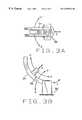
- FIGS. 3A and 3Bare a side and top view of an articulation apparatus for use with the apparatus of FIGS. 1 and 2;
- FIG. 4is a view of an alternate coil or magnet articulation apparatus for procedures requiring force with mobile vision
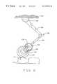
- FIG. 6is a drawing of a ceiling mounted embodiment of a permanent magnet on an arm that may be articulated either manually or by computer control;
- FIG. 8is a drawing showing the relationship of the magnetic field lines of FIG. 7 to the operating region when the electromagnetic coil is rotated along an axis.
- FIGS. 9A and 9Bdepict the plane of the windings of a pair of coils, or a split coil, in another embodiment of the invention.
- FIG. 10is a drawing of a dolly-mounted embodiment of a permanent magnet on an arm that may be articulated either manually or by computer control;
- FIG. 6is a drawing of an embodiment of an articulation apparatus in accordance with the present invention.
- This apparatusemploys a magnet 101 which is preferably a permanent magnet.
- This apparatusis similar to, but is stronger than and is an extended version of a type of articulated arm such as one that holds a dentist's drill.
- the illustrated embodimentshows a universal hinge 105 mounting a section 103 of the arm to a base 102 such as a ceiling, although the arm could be mounted elsewhere, for example, to a support dolly on the floor, as shown in FIG. 10 .
- An opposite end of arm section 103is connected to another arm section 104 by another hinge 106 .
- Two sections of the arm 103 , 104are hinged at two points 105 and 106 to allow adjustable placement of magnet 101 .
- This movementprovides magnetic field lines 107 in a patient 111 for guidance and/or motivating such as by pulling (the latter by the gradient of the magnetic field) of magnetic surgery device or implant 110 within patient 111 .
- the term “directing”may include either or both of guiding (navigating) and motivating such as by pushing or pulling.
- Pivots 108 and 109allow magnet 101 to be rotated to provide all angles of navigation and motivation.
- a locating device 112may be provided, e.g., at or near magnet 101 , to aid in and keep track of the positioning of magnet 101 . While this embodiment has been described as employing a permanent magnet 101 , it is also possible for it to be appropriately modified to use an electromagnet, as would be apparent to one of ordinary skill in the art. It would also be apparent to one of ordinary skill in the art that an imaging device might also be supported and positioned in tandem with the magnet, or along side thereof, as shown in FIG. 10 .
- FIG. 1A side view of another embodiment of a portion of an apparatus in accordance with the invention is shown in FIG. 1 .
- the apparatusincludes a first X-ray source 12 located above a bed 14 , a second x-ray source 16 located above and to one side of bed 14 , a pair of axial magnets 18 , and a bed articulating system 20 and 22 .
- the axial magnets 18are optional, but are included in the preferred embodiment to provide magnetic fields along the direction of the body axis where some types of moving magnets (not shown, but to be described below) cannot provide such fields.
- Axial magnetsmay comprise normally conducting or superconducting coils.
- the bed articulating systemis shown in two parts 20 and 22 because an articulation point 24 is located between the two parts 20 and 22 .
- Articulation point 24is a location at which an articulated magnet pivot may rest.
- the articulation magnet pivotis not shown in FIG. 1, however.
- X-ray sources 12 and 16are supported by support struts 26 or any other suitable structure so that they project their beams at imaging plates 28 and 30 , respectively, crossing through a location above the bed where a region of interest of a patient 32 would be positioned (operating region) during an operation.
- a magnetic seed or other magnetically guided surgical or medicinal-carrying implementwould be either temporarily or permanently implanted (implant) as a magnetic structure in the body of patient 32 in the operating region, or region of interest.
- Imaging plates 28 and 30are preferably of a type capable of transferring an image to a computer and of being generally unaffected by strong magnetic fields.
- FIG. 2A view of the apparatus of FIG. 1 from another perspective is provided by FIG. 2, which shows the apparatus as it might appear if one were positioned to the right of the head of patient 32 in FIG. 1 while looking at the apparatus.
- FIG. 2more clearly shows the intersection of X-ray beams 34 and 36 in a region of interest of the body of patient 32 (operating region).
- the bed articulation system 20 and 22is designed to move bed 14 at least along a longitudinal axis, and may also be designed to move vertically, laterally, or otherwise.
- motion of the bed 14while desirable, is not necessary to the operation of the invention, which is instead more generally concerned with the articulation of a magnet in a region around patient 32 .
- Articulation point 24 in FIGS. 1 and 2represents a position in which a coil or magnet articulation system may be mounted in accordance with this invention.
- One type of articulation system suitable for use in this inventionis shown in FIGS. 3A and 3B.
- the type of articulation system shown hereis suitable for surgical procedures requiring a magnetic field only with fixed vision, i.e., the X-ray system comprising projection tubes 12 , 16 and screens 28 , 30 in FIGS. 1 and 2 do not move.
- FIG. 3Ashows an articulation support 50 , which may be provided in the position shown in FIGS. 1 and 2 at articulation point 24 .
- the articulation supportis provided with servo control mechanisms (not shown) to provide movement of a coil or permanent magnet 52 along an arcuate arm 54 along a polar angle A-A′ and radially as indicated by arrow B. Motion of the entire arm 54 may optionally be provided by pivoting arm 54 in a direction C-C′, although this motion is not required.
- FIG. 3Bshows a top view of the apparatus shown in FIG. 3A, showing that arm 54 sweeps along an azimuthal angle, limited by the placement of axial coils 18 (shown in FIGS. 1 and 2 ).
- the apparatus as shownprovides coverage of a lower portion of either the right or the left side of a patient 32 (not shown in FIGS. 3 A and 3 B).
- Arm 54may preferably comprise a track and gimbal assembly, for example, although other arms may be used as would be apparent to one of ordinary skill in the art.
- a second articulation apparatus 50 , 52 , 54may be provided to provide coverage of the other side.
- arm 54provides more than 90° of polar motion for magnet 52 .
- arm 54may itself cover an angle greater than 90° so that magnet 52 can move around the entire left or right side of patient 32 .
- arm 54may itself be made moveable through articulation support 50 , so that it moves in an arcuate direction indicated by arrow E in FIGS. 3A and 3B. Such motion allows for complete coverage of the back of patient 32 . Combinations of these variations are also possible.
- arm 54may preferably comprise a track and gimbal assembly.
- FIG. 4An alternate embodiment of a magnet articulation system is shown in FIG. 4 .
- Magnet or coil 52is mounted on a ring support 54 ′ which, in this embodiment, also carries X-ray projectors 12 and 16 , as well as imaging plates 28 and 30 .
- the entire ringis supported by articulation support 50 so that it can be moved, preferably under control of a servo control system, in a polar angle indicated by arrow E.
- the ringcan also be moved in an azimuthal direction similar to that shown in FIG. 3 B.
- Magnet 52can also move radially as indicated by arrow B in FIG. 4 .
- struts 26would be omitted from the bed and axial magnet assembly of FIGS.
- X-ray tube 12 , 16 and its corresponding imaging plate 28 , 30could be fixedly attached to a bed and axial magnet assembly rather than to the magnet articulation assembly shown in FIG. 4, or any of the elements shown mounted to ring 54 ′ could be separately moveable around ring 54 ′ without ring 54 ′ being moved.
- magnet or coil 52comprises a permanent magnet
- magnet or coil 52it is preferable to provide a pivot so that magnetic poles can be rotated to supply a magnetic field in any necessary direction during a surgical procedure.
- This pivotingis illustrated by the rotation of magnet 52 in the sequence of FIGS. 5A, 5 B, and 5 C about a pivot 56 attached to ring 54 (or 54 ′). The north and south poles of the magnet are shown.
- the magnet 52should preferably be retracted either through a retraction motion as indicated in arrow B in FIGS. 3A and 4, or the support arm 54 should preferably be pivoted downward, away from the patient along arrow C in FIG. 3 A.
- a magnetic shield(not shown) of a suitable material may simply be interposed between magnet 52 and the patient to prevent the magnetic field of the rotating magnet from adversely affecting the motion of a magnet seed implanted in the patient.
- a robotic arm assemblymay be used.
- Robotic arm manipulationis standard in many industries. Examples of robotic arm manipulation may be found in U.S. Pat. No. 5,321,353 issued Jun. 14, 1994 to D. Furness, entitled “System and Method for Precisely Positioning a Robotic Arm,” U.S. Pat. No. 5,086,401 issued Feb. 4, 1992 to E. Glassman, et al., entitled “Image-directed Robotic System for Precise Robotic Surgery Including Redundant Consistency Checking,” U.S. Pat. No. 4,569,627 issued Feb. 11, 1986 to S. Simunovic, entitled “Robotic Manipulator,” U.S. Pat. No.
- the articulationbe computer-controlled, so that simpler and possibly more effective field solutions may be achieved.
- a limited number of magnetse.g., only the moving magnet 52 or the moving magnet in conjunction with either one or two axial magnets 18
- far simpler field solutionsare possible and sufficient than is the case with a larger plurality of magnets, each of which is controlled separately or in conjunction with another in pairs.
- a controlling apparatussuch as a computer (not shown) may be provided and coupled to articulation systems 20 , 22 , the pair of axial coils 18 , the articulation and rotation systems illustrated in FIGS.
- 3A, 3 B, 4 , 5 A, 5 B, and 5 C(or the alternate robotic arm assembly), as well as the imaging system 12 , 16 , 28 , 30 , as well as control current in a coil used as magnet 52 .
- This computer controlwould allow for close coordination of magnetic surgery with concurrent imaging.
- This aspect of the inventionmakes it particularly useful for surgery in sensitive areas of a patient's body such as the brain.
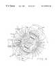
- FIG. 7is a drawing illustrating a relationship between the magnetic field lines of a preferred embodiment of an electromagnetic coil and an operating region of a patient, when the electromagnetic coil is in a first orientation, axes 202 and 204 of electromagnetic coil 206 are diagrammatically shown relative to an operating region 208 .
- the operating regionmay, for example, be a patient's brain, but could be another part of the body.
- Axis 204is shown as a point, because it represents an axis perpendicular to the plane depicted in FIG. 7, which view is shown looking down on a patient.
- a third axis 220 perpendicular to the other twois an axis of symmetry of the coil, i.e., the axis about which the turns of the coil are wound.
- axis of symmetry of the coili.e., the axis about which the turns of the coil are wound.
- Rotation about axis 202will provide field line components that can be represented as going into, or emerging from, the plane represented by FIG. 7, depending upon whether the desired “spot” (i.e., the location at which the magnetic field having the desired direction is to be provided) is to the left or to the right of axis 202 , and on the direction of rotation about axis 202 .
- the desired “spot”i.e., the location at which the magnetic field having the desired direction is to be provided
- Rotation about axis 204can shift field line directions from left to right, or the reverse, and often with a relatively small angle of rotation (i.e., as compared to 180°).
- This economy of rotationi.e. sensitivity, is better illustrated by reference to FIG. 8 , which is a drawing showing the relationship of the magnetic field lines of FIG. 7 to the operating region when the electromagnetic coil is rotated along an axis.
- FIG. 8is a drawing showing the relationship of the magnetic field lines of FIG. 7 to the operating region when the electromagnetic coil is rotated along an axis.
- FIG. 8is a drawing showing the relationship of the magnetic field lines of FIG. 7 to the operating region when the electromagnetic coil is rotated along an axis.
- FIG. 8is a drawing showing the relationship of the magnetic field lines of FIG. 7 to the operating region when the electromagnetic coil is rotated along an axis.
- FIG. 8is a drawing showing the relationship of the magnetic field lines of FIG. 7 to the operating region when the electromagnetic coil is rotated along an axi
- magnet 206its inner coil diameter D 1 as indicated in FIG. 8 is 16 inches, while its outer coil diameter D 2 is 20 inches.
- the coil width W in the axial directionis 8 inches. (As noted above, the figures are not necessarily drawn to scale.) With these dimensions, when coil 206 is a superconducting coil with 20,000 A/cm 2 , it can create approximately 0.4 Tesla or greater at any region of procedure in an operating region 208 of a patient's brain.
- An advantage of this navigational/motivational system and methodis that significant magnetic fields in all directions at all locations in a brain or other body part positioned within an operating region can be obtained merely by rotation of a magnet, without other translational movement.
- a ratio of a side field (i.e., the 90° off-axis magnetic field magnitude) to an axial fieldis large, so that not as much power is wasted in having to drive a desired minimum field at all angles of orientation. Maintaining such field ratios decreases coil size and cost, and can make manipulation of the magnet easier.
- axial field magnitudeis about 1.4 times the side field magnitude at most distances.
- magnet coil 206 dimensionshave been optimized for some conditions, coils of somewhat different dimensions and shapes can be optimized differently for different magnetically-guided surgical applications.
- both or either of the side fields and the axial fieldsat various times during a surgical procedure, will provide the necessary directed fields, and that reversal of field direction can be achieved by rotation about an appropriate axis, without other translational movement.
- the magnetic field lines, or the gradient of the magnetic fieldis used either to move or at least direct the motion of the surgical device.
- Changes in the direction of the magnetic field lines or of the gradientare made to provide changes in the direction and/or orientation of the surgical device.
- a pure rotation in the dihedral plane of an intended turncan be accomplished without changing the coil current, with proper control of the axes of rotation of the coil.
- the magnetcan be moved translationally away from the patient, rotated, and then brought back into position, with or without altering currents. It will be understood that similar movements of a permanent magnet may be used to direct and perhaps motivate the surgical device, although the steps involving changes in coil current would no longer be applicable in this case.
- Still another embodiment of the inventionwhich may actually be used in the other several embodiments of the invention, comprises an articulated magnet, which may be either a pair of permanent magnets, or an electromagnet having current relationships as shown in FIGS. 9A and 9B.
- an articulated magnetwhich may be either a pair of permanent magnets, or an electromagnet having current relationships as shown in FIGS. 9A and 9B.
- the plane of the windings of such a coil, or two coils, each shaped in the approximate form of a semi-circleis energized by currents flowing in opposite senses.
- This same fieldmay be created with a single coil having its two halves twisted, as shown.
- two permanent magnetsare placed side by side to make a single magnet assembly with a north and south pole facing the operating region.
- the field directly in front of the magnetis parallel to the magnet face, while the fields closer to the magnet edges are perpendicular to the magnet face.
- a rotation of the magnet about its short axis, plus a lateral translationprovides all possible magnetic field orientations in the operating region.
- the magnets employedwhether permanent magnets (such as two permanent magnets side-by-side with opposite polarities) or electromagnets (such as shown in FIGS. 9 A and 9 B), preferably provide a quadrupole magnetic field, which is preferred because the resulting distribution of field lines is particularly suited to controlling the application of magnetic field by articulation.
Landscapes
- Health & Medical Sciences (AREA)
- Life Sciences & Earth Sciences (AREA)
- Surgery (AREA)
- Engineering & Computer Science (AREA)
- Animal Behavior & Ethology (AREA)
- Veterinary Medicine (AREA)
- Biomedical Technology (AREA)
- Heart & Thoracic Surgery (AREA)
- Medical Informatics (AREA)
- Molecular Biology (AREA)
- Nuclear Medicine, Radiotherapy & Molecular Imaging (AREA)
- General Health & Medical Sciences (AREA)
- Public Health (AREA)
- Robotics (AREA)
- Pathology (AREA)
- Oral & Maxillofacial Surgery (AREA)
- Physics & Mathematics (AREA)
- Biophysics (AREA)
- Optics & Photonics (AREA)
- Radiology & Medical Imaging (AREA)
- Apparatus For Radiation Diagnosis (AREA)
- Media Introduction/Drainage Providing Device (AREA)
- Prostheses (AREA)
Abstract
Description
Claims (8)
Priority Applications (1)
| Application Number | Priority Date | Filing Date | Title |
|---|---|---|---|
| US09/189,633US6459924B1 (en) | 1997-11-12 | 1998-11-10 | Articulated magnetic guidance systems and devices and methods for using same for magnetically-assisted surgery |
Applications Claiming Priority (2)
| Application Number | Priority Date | Filing Date | Title |
|---|---|---|---|
| US6510597P | 1997-11-12 | 1997-11-12 | |
| US09/189,633US6459924B1 (en) | 1997-11-12 | 1998-11-10 | Articulated magnetic guidance systems and devices and methods for using same for magnetically-assisted surgery |
Publications (1)
| Publication Number | Publication Date |
|---|---|
| US6459924B1true US6459924B1 (en) | 2002-10-01 |
Family
ID=22060371
Family Applications (1)
| Application Number | Title | Priority Date | Filing Date |
|---|---|---|---|
| US09/189,633Expired - Fee RelatedUS6459924B1 (en) | 1997-11-12 | 1998-11-10 | Articulated magnetic guidance systems and devices and methods for using same for magnetically-assisted surgery |
Country Status (5)
| Country | Link |
|---|---|
| US (1) | US6459924B1 (en) |
| EP (1) | EP1030589A2 (en) |
| JP (1) | JP2001522623A (en) |
| AU (1) | AU1796499A (en) |
| WO (1) | WO1999023934A2 (en) |
Cited By (114)
| Publication number | Priority date | Publication date | Assignee | Title |
|---|---|---|---|---|
| US20010038683A1 (en)* | 1998-11-03 | 2001-11-08 | Ritter Rogers C. | Open field system for magnetic surgery |
| US20030050527A1 (en)* | 2001-05-04 | 2003-03-13 | Peter Fox | Apparatus and methods for delivery of transcranial magnetic stimulation |
| US20040249262A1 (en)* | 2003-03-13 | 2004-12-09 | Werp Peter R. | Magnetic navigation system |
| US20050035237A1 (en)* | 2003-08-15 | 2005-02-17 | International Business Machines Corporation | Apparatus and method to releaseably attach a tape leader pin |
| US20050096589A1 (en)* | 2003-10-20 | 2005-05-05 | Yehoshua Shachar | System and method for radar-assisted catheter guidance and control |
| US20050187424A1 (en)* | 2003-11-28 | 2005-08-25 | Klaus Hambuchen | Apparatus for directing a magnetic element in a body of a patient |
| US20060036163A1 (en)* | 2004-07-19 | 2006-02-16 | Viswanathan Raju R | Method of, and apparatus for, controlling medical navigation systems |
| US20060052656A1 (en)* | 2004-09-09 | 2006-03-09 | The Regents Of The University Of California | Implantable devices using magnetic guidance |
| US20060079745A1 (en)* | 2004-10-07 | 2006-04-13 | Viswanathan Raju R | Surgical navigation with overlay on anatomical images |
| US20060142631A1 (en)* | 2004-12-29 | 2006-06-29 | Attila Meretei | Systems and methods for occluding a blood vessel |
| US20060144407A1 (en)* | 2004-07-20 | 2006-07-06 | Anthony Aliberto | Magnetic navigation manipulation apparatus |
| US20060144408A1 (en)* | 2004-07-23 | 2006-07-06 | Ferry Steven J | Micro-catheter device and method of using same |
| US20060269108A1 (en)* | 2005-02-07 | 2006-11-30 | Viswanathan Raju R | Registration of three dimensional image data to 2D-image-derived data |
| US20060276867A1 (en)* | 2005-06-02 | 2006-12-07 | Viswanathan Raju R | Methods and devices for mapping the ventricle for pacing lead placement and therapy delivery |
| US20060281989A1 (en)* | 2005-05-06 | 2006-12-14 | Viswanathan Raju R | Voice controlled user interface for remote navigation systems |
| US20060278246A1 (en)* | 2003-05-21 | 2006-12-14 | Michael Eng | Electrophysiology catheter |
| US20060281990A1 (en)* | 2005-05-06 | 2006-12-14 | Viswanathan Raju R | User interfaces and navigation methods for vascular navigation |
| US20070021731A1 (en)* | 1997-11-12 | 2007-01-25 | Garibaldi Jeffrey M | Method of and apparatus for navigating medical devices in body lumens |
| US20070021744A1 (en)* | 2005-07-07 | 2007-01-25 | Creighton Francis M Iv | Apparatus and method for performing ablation with imaging feedback |
| US20070019330A1 (en)* | 2005-07-12 | 2007-01-25 | Charles Wolfersberger | Apparatus for pivotally orienting a projection device |
| US20070021742A1 (en)* | 2005-07-18 | 2007-01-25 | Viswanathan Raju R | Estimation of contact force by a medical device |
| US20070030958A1 (en)* | 2005-07-15 | 2007-02-08 | Munger Gareth T | Magnetically shielded x-ray tube |
| US20070038064A1 (en)* | 2005-07-08 | 2007-02-15 | Creighton Francis M Iv | Magnetic navigation and imaging system |
| US20070038410A1 (en)* | 2005-08-10 | 2007-02-15 | Ilker Tunay | Method and apparatus for dynamic magnetic field control using multiple magnets |
| US20070038065A1 (en)* | 2005-07-07 | 2007-02-15 | Creighton Francis M Iv | Operation of a remote medical navigation system using ultrasound image |
| US20070038074A1 (en)* | 1998-02-09 | 2007-02-15 | Ritter Rogers C | Method and device for locating magnetic implant source field |
| US20070043455A1 (en)* | 2005-07-26 | 2007-02-22 | Viswanathan Raju R | Apparatus and methods for automated sequential movement control for operation of a remote navigation system |
| US20070040670A1 (en)* | 2005-07-26 | 2007-02-22 | Viswanathan Raju R | System and network for remote medical procedures |
| US20070055124A1 (en)* | 2005-09-01 | 2007-03-08 | Viswanathan Raju R | Method and system for optimizing left-heart lead placement |
| US20070062546A1 (en)* | 2005-06-02 | 2007-03-22 | Viswanathan Raju R | Electrophysiology catheter and system for gentle and firm wall contact |
| US20070088197A1 (en)* | 2000-02-16 | 2007-04-19 | Sterotaxis, Inc. | Magnetic medical devices with changeable magnetic moments and method of navigating magnetic medical devices with changeable magnetic moments |
| US20070088077A1 (en)* | 1991-02-26 | 2007-04-19 | Plasse Terry F | Appetite stimulation and reduction of weight loss in patients suffering from symptomatic hiv infection |
| US7276044B2 (en) | 2001-05-06 | 2007-10-02 | Stereotaxis, Inc. | System and methods for advancing a catheter |
| US20070258639A1 (en)* | 2006-05-08 | 2007-11-08 | Siemens Aktiengesellschaft | Method for producing a three-dimensional image dataset of a target volume |
| US7309316B1 (en)* | 2004-03-01 | 2007-12-18 | Flynn Edward R | Magnetic needle biopsy |
| US20070299550A1 (en)* | 2004-09-28 | 2007-12-27 | Osaka University | Three-Dimensional Guidance System And Method , And Drug Delivery System |
| US20080006280A1 (en)* | 2004-07-20 | 2008-01-10 | Anthony Aliberto | Magnetic navigation maneuvering sheath |
| US20080015427A1 (en)* | 2006-06-30 | 2008-01-17 | Nathan Kastelein | System and network for remote medical procedures |
| US20080103388A1 (en)* | 2006-09-25 | 2008-05-01 | Siemens Aktiengesellschaft | Medical examination and/or treatment apparatus |
| US20080249395A1 (en)* | 2007-04-06 | 2008-10-09 | Yehoshua Shachar | Method and apparatus for controlling catheter positioning and orientation |
| US7525309B2 (en) | 2005-12-30 | 2009-04-28 | Depuy Products, Inc. | Magnetic sensor array |
| US7537570B2 (en) | 2006-09-11 | 2009-05-26 | Stereotaxis, Inc. | Automated mapping of anatomical features of heart chambers |
| US7543239B2 (en) | 2004-06-04 | 2009-06-02 | Stereotaxis, Inc. | User interface for remote control of medical devices |
| US7567233B2 (en) | 2006-09-06 | 2009-07-28 | Stereotaxis, Inc. | Global input device for multiple computer-controlled medical systems |
| US20090275828A1 (en)* | 2008-05-01 | 2009-11-05 | Magnetecs, Inc. | Method and apparatus for creating a high resolution map of the electrical and mechanical properties of the heart |
| US20100105984A1 (en)* | 2008-10-21 | 2010-04-29 | Reuben Brewer | System and Method for Guiding a Medical Instrument with Magnetic Force Control |
| US7708696B2 (en) | 2005-01-11 | 2010-05-04 | Stereotaxis, Inc. | Navigation using sensed physiological data as feedback |
| US7747960B2 (en) | 2006-09-06 | 2010-06-29 | Stereotaxis, Inc. | Control for, and method of, operating at least two medical systems |
| US7751867B2 (en) | 2004-12-20 | 2010-07-06 | Stereotaxis, Inc. | Contact over-torque with three-dimensional anatomical data |
| US7757694B2 (en) | 1999-10-04 | 2010-07-20 | Stereotaxis, Inc. | Method for safely and efficiently navigating magnetic devices in the body |
| US7769427B2 (en) | 2002-07-16 | 2010-08-03 | Magnetics, Inc. | Apparatus and method for catheter guidance control and imaging |
| US7769444B2 (en) | 2005-07-11 | 2010-08-03 | Stereotaxis, Inc. | Method of treating cardiac arrhythmias |
| US7766856B2 (en) | 2001-05-06 | 2010-08-03 | Stereotaxis, Inc. | System and methods for advancing a catheter |
| US7818076B2 (en) | 2005-07-26 | 2010-10-19 | Stereotaxis, Inc. | Method and apparatus for multi-system remote surgical navigation from a single control center |
| US7869854B2 (en) | 2006-02-23 | 2011-01-11 | Magnetecs, Inc. | Apparatus for magnetically deployable catheter with MOSFET sensor and method for mapping and ablation |
| US7961924B2 (en) | 2006-08-21 | 2011-06-14 | Stereotaxis, Inc. | Method of three-dimensional device localization using single-plane imaging |
| US7966059B2 (en) | 1999-10-04 | 2011-06-21 | Stereotaxis, Inc. | Rotating and pivoting magnet for magnetic navigation |
| US8024024B2 (en) | 2007-06-27 | 2011-09-20 | Stereotaxis, Inc. | Remote control of medical devices using real time location data |
| US8027714B2 (en)* | 2005-05-27 | 2011-09-27 | Magnetecs, Inc. | Apparatus and method for shaped magnetic field control for catheter, guidance, control, and imaging |
| US20110237871A1 (en)* | 2010-03-25 | 2011-09-29 | Allergan, Inc. | Controller support apparatus |
| US8060184B2 (en) | 2002-06-28 | 2011-11-15 | Stereotaxis, Inc. | Method of navigating medical devices in the presence of radiopaque material |
| US8068648B2 (en) | 2006-12-21 | 2011-11-29 | Depuy Products, Inc. | Method and system for registering a bone of a patient with a computer assisted orthopaedic surgery system |
| US8114032B2 (en)* | 2001-05-06 | 2012-02-14 | Stereotaxis, Inc. | Systems and methods for medical device advancement and rotation |
| US8118754B1 (en) | 2007-11-15 | 2012-02-21 | Flynn Edward R | Magnetic needle biopsy |
| US8135185B2 (en) | 2006-10-20 | 2012-03-13 | Stereotaxis, Inc. | Location and display of occluded portions of vessels on 3-D angiographic images |
| US8196590B2 (en) | 2003-05-02 | 2012-06-12 | Stereotaxis, Inc. | Variable magnetic moment MR navigation |
| WO2012048102A3 (en)* | 2010-10-06 | 2012-07-12 | The Board Of Regents Of The University Of Texas System | Systems and methods for magnetically charging and discharging a member configured for medical use |
| US8231618B2 (en) | 2007-11-05 | 2012-07-31 | Stereotaxis, Inc. | Magnetically guided energy delivery apparatus |
| US8244824B2 (en) | 2006-09-06 | 2012-08-14 | Stereotaxis, Inc. | Coordinated control for multiple computer-controlled medical systems |
| US8242972B2 (en) | 2006-09-06 | 2012-08-14 | Stereotaxis, Inc. | System state driven display for medical procedures |
| US8273081B2 (en) | 2006-09-08 | 2012-09-25 | Stereotaxis, Inc. | Impedance-based cardiac therapy planning method with a remote surgical navigation system |
| US8308628B2 (en) | 2009-11-02 | 2012-11-13 | Pulse Therapeutics, Inc. | Magnetic-based systems for treating occluded vessels |
| CN102920513A (en)* | 2012-11-13 | 2013-02-13 | 吉林大学 | Augmented reality system experiment platform based on projector |
| US8419681B2 (en) | 2002-11-18 | 2013-04-16 | Stereotaxis, Inc. | Magnetically navigable balloon catheters |
| US8447379B2 (en) | 2006-11-16 | 2013-05-21 | Senior Scientific, LLC | Detection, measurement, and imaging of cells such as cancer and other biologic substances using targeted nanoparticles and magnetic properties thereof |
| US8457714B2 (en) | 2008-11-25 | 2013-06-04 | Magnetecs, Inc. | System and method for a catheter impedance seeking device |
| US20130317281A1 (en)* | 2010-10-08 | 2013-11-28 | M. Bret Schneider | Transcranial magnetic stimulation for improved analgesia |
| US8862200B2 (en) | 2005-12-30 | 2014-10-14 | DePuy Synthes Products, LLC | Method for determining a position of a magnetic source |
| US9095270B2 (en) | 2009-11-06 | 2015-08-04 | Senior Scientific Llc | Detection, measurement, and imaging of cells such as cancer and other biologic substances using targeted nanoparticles and magnetic properties thereof |
| US9111016B2 (en) | 2007-07-06 | 2015-08-18 | Stereotaxis, Inc. | Management of live remote medical display |
| US9265965B2 (en) | 2011-09-30 | 2016-02-23 | Board Of Regents, The University Of Texas System | Apparatus and method for delivery of transcranial magnetic stimulation using biological feedback to a robotic arm |
| US9314222B2 (en) | 2005-07-07 | 2016-04-19 | Stereotaxis, Inc. | Operation of a remote medical navigation system using ultrasound image |
| US9339285B2 (en) | 2013-03-12 | 2016-05-17 | Levita Magnetics International Corp. | Grasper with magnetically-controlled positioning |
| US9352167B2 (en) | 2006-05-05 | 2016-05-31 | Rio Grande Neurosciences, Inc. | Enhanced spatial summation for deep-brain transcranial magnetic stimulation |
| US9381374B2 (en) | 2009-01-07 | 2016-07-05 | Rio Grande Neurosciences, Inc. | Shaped coils for transcranial magnetic stimulation |
| US9486639B2 (en) | 2006-05-05 | 2016-11-08 | The Board Of Trustees Of The Leland Stanford Junior University | Trajectory-based deep-brain stereotactic transcranial magnetic stimulation |
| US9492679B2 (en) | 2010-07-16 | 2016-11-15 | Rio Grande Neurosciences, Inc. | Transcranial magnetic stimulation for altering susceptibility of tissue to pharmaceuticals and radiation |
| US20170112483A1 (en)* | 2014-05-20 | 2017-04-27 | Ajou University Industry-Academic Cooperation Foundation | Surgical traction apparatus |
| US9655539B2 (en) | 2009-11-09 | 2017-05-23 | Magnetecs, Inc. | System and method for targeting catheter electrodes |
| CN106963492A (en)* | 2015-10-29 | 2017-07-21 | 香港生物医学工程有限公司 | Magnetic anchoring robot system |
| US20170252539A1 (en)* | 2016-03-02 | 2017-09-07 | Cook Medical Technologies, LLC | Magnetic guidance system particularly for neurological device |
| US9844391B2 (en) | 2009-02-06 | 2017-12-19 | Levita Magnetics International Corp. | Remote traction and guidance system for mini-invasive surgery |
| US9883878B2 (en) | 2012-05-15 | 2018-02-06 | Pulse Therapeutics, Inc. | Magnetic-based systems and methods for manipulation of magnetic particles |
| US9964469B2 (en) | 2005-02-28 | 2018-05-08 | Imagion Biosystems, Inc. | Magnetic needle separation and optical monitoring |
| US10010370B2 (en) | 2013-03-14 | 2018-07-03 | Levita Magnetics International Corp. | Magnetic control assemblies and systems therefor |
| US10194825B2 (en) | 2009-11-06 | 2019-02-05 | Imagion Biosystems Inc. | Methods and apparatuses for the localization and treatment of disease such as cancer |
| US10537348B2 (en) | 2014-01-21 | 2020-01-21 | Levita Magnetics International Corp. | Laparoscopic graspers and systems therefor |
| US10537713B2 (en) | 2009-05-25 | 2020-01-21 | Stereotaxis, Inc. | Remote manipulator device |
| US10682132B2 (en)* | 2001-12-03 | 2020-06-16 | P Tech, Llc | System for magnetic movement of tissue and implants |
| US10905511B2 (en) | 2015-04-13 | 2021-02-02 | Levita Magnetics International Corp. | Grasper with magnetically-controlled positioning |
| US11020137B2 (en) | 2017-03-20 | 2021-06-01 | Levita Magnetics International Corp. | Directable traction systems and methods |
| US11045658B2 (en)* | 2018-06-28 | 2021-06-29 | Medtronic, Inc. | Receive coil configurations for implantable medical device |
| CN113056237A (en)* | 2018-11-28 | 2021-06-29 | 汉阳大学校产学协力团 | Magnetic field driving system |
| US11056267B2 (en)* | 2018-06-28 | 2021-07-06 | Medtronic, Inc. | Receive coil configurations for implantable medical device |
| US11413026B2 (en) | 2007-11-26 | 2022-08-16 | Attractive Surgical, Llc | Magnaretractor system and method |
| US11583354B2 (en) | 2015-04-13 | 2023-02-21 | Levita Magnetics International Corp. | Retractor systems, devices, and methods for use |
| US11813470B2 (en) | 2018-06-28 | 2023-11-14 | Medtronic, Inc. | Multi-axis coil for implantable medical device |
| US11894186B2 (en) | 2020-06-17 | 2024-02-06 | Multi-Scale Medical Robotics Center Limited | Parallel mobile coil mechanism for magnetic manipulation in large workspace |
| US11918315B2 (en) | 2018-05-03 | 2024-03-05 | Pulse Therapeutics, Inc. | Determination of structure and traversal of occlusions using magnetic particles |
| US20240299174A1 (en)* | 2007-06-05 | 2024-09-12 | P Tech, Llc | Magnetic joint implant |
| US12171443B1 (en) | 2021-03-09 | 2024-12-24 | Pulse Therapeutics, Inc. | Magnetically controlled flow generation |
| US12262971B2 (en) | 2016-01-08 | 2025-04-01 | Levita Magnetics International Corp. | One-operator surgical system and methods of use |
| US12369981B2 (en) | 2023-02-07 | 2025-07-29 | Depuy Ireland Unlimited Company | Systems and methods for bone model registration with adaptive soft tissue thickness |
| US12403318B2 (en) | 2021-11-24 | 2025-09-02 | Medtronic, Inc. | Ceramic enclosure for rechargeable medical devices |
Families Citing this family (12)
| Publication number | Priority date | Publication date | Assignee | Title |
|---|---|---|---|---|
| AU1630601A (en)* | 1999-10-04 | 2001-05-10 | Stereotaxis, Inc. | Method for safely and efficiently navigating magnetic devices in the body |
| GB0014028D0 (en)* | 2000-06-09 | 2000-08-02 | Oxford Instr Ltd | Catheter guide assembly |
| JP4147315B2 (en)* | 2002-09-13 | 2008-09-10 | Hoya株式会社 | Magnetic anchor remote guidance system |
| WO2007125676A1 (en)* | 2006-04-26 | 2007-11-08 | Hitachi Medical Corporation | Magnetic induction drug delivery system |
| JP5020533B2 (en)* | 2006-04-27 | 2012-09-05 | 株式会社日立メディコ | Drug delivery system and computer program for controlling the same |
| WO2010041714A1 (en)* | 2008-10-10 | 2010-04-15 | 学校法人自治医科大学 | Surgery system for endoscopic submucosal dissection (esd) and surgery method |
| WO2010068005A2 (en)* | 2008-12-12 | 2010-06-17 | Rebo | Surgical robot |
| JP5294206B2 (en)* | 2009-05-27 | 2013-09-18 | 独立行政法人国立がん研究センター | Magnetic guidance device for long inserts |
| JP5372178B2 (en)* | 2009-12-25 | 2013-12-18 | 株式会社Ihi | Drug delivery control device |
| US10252030B2 (en)* | 2017-01-17 | 2019-04-09 | Cook Medical Technologies Llc | Handheld magnetic gun for guide wire manipulation |
| JP7515405B2 (en) | 2018-05-18 | 2024-07-12 | マックス‐プランク‐ゲゼルシャフト・ツア・フェルデルンク・デア・ヴィッセンシャフテン・アインゲトラーゲナー・フェライン | Magnetic field generator |
| CN112515610B (en)* | 2020-11-30 | 2021-10-22 | 元化智能科技(深圳)有限公司 | Driving method, device and system of wireless capsule endoscope |
Citations (13)
| Publication number | Priority date | Publication date | Assignee | Title |
|---|---|---|---|---|
| US3043309A (en)* | 1959-09-29 | 1962-07-10 | Avco Corp | Method of performing intestinal intubation |
| US3358676A (en)* | 1962-11-30 | 1967-12-19 | Yeda Res & Dev | Magnetic propulsion of diagnostic or therapeutic elements through the body ducts of animal or human patients |
| FR2252107A1 (en)* | 1973-11-27 | 1975-06-20 | Commissariat Energie Atomique | |
| US4244362A (en) | 1978-11-29 | 1981-01-13 | Anderson Charles C | Endotracheal tube control device |
| US4809713A (en) | 1987-10-28 | 1989-03-07 | Joseph Grayzel | Catheter with magnetic fixation |
| US5353807A (en) | 1992-12-07 | 1994-10-11 | Demarco Thomas J | Magnetically guidable intubation device |
| US5681260A (en) | 1989-09-22 | 1997-10-28 | Olympus Optical Co., Ltd. | Guiding apparatus for guiding an insertable body within an inspected object |
| US5758667A (en) | 1995-01-26 | 1998-06-02 | Siemens Elema Ab | Device for locating a port on a medical implant |
| US5779694A (en)* | 1990-01-10 | 1998-07-14 | The University Of Virginia Alumni Patents Foundation | Magnetic stereotactic system for treatment delivery |
| US5843153A (en)* | 1997-07-15 | 1998-12-01 | Sulzer Intermedics Inc. | Steerable endocardial lead using magnetostrictive material and a magnetic field |
| US6014580A (en)* | 1997-11-12 | 2000-01-11 | Stereotaxis, Inc. | Device and method for specifying magnetic field for surgical applications |
| US6015414A (en)* | 1997-08-29 | 2000-01-18 | Stereotaxis, Inc. | Method and apparatus for magnetically controlling motion direction of a mechanically pushed catheter |
| US6241671B1 (en)* | 1998-11-03 | 2001-06-05 | Stereotaxis, Inc. | Open field system for magnetic surgery |
- 1998
- 1998-11-10AUAU17964/99Apatent/AU1796499A/ennot_activeAbandoned
- 1998-11-10WOPCT/US1998/023983patent/WO1999023934A2/ennot_activeApplication Discontinuation
- 1998-11-10JPJP2000520039Apatent/JP2001522623A/enactivePending
- 1998-11-10USUS09/189,633patent/US6459924B1/ennot_activeExpired - Fee Related
- 1998-11-10EPEP98962807Apatent/EP1030589A2/ennot_activeWithdrawn
Patent Citations (13)
| Publication number | Priority date | Publication date | Assignee | Title |
|---|---|---|---|---|
| US3043309A (en)* | 1959-09-29 | 1962-07-10 | Avco Corp | Method of performing intestinal intubation |
| US3358676A (en)* | 1962-11-30 | 1967-12-19 | Yeda Res & Dev | Magnetic propulsion of diagnostic or therapeutic elements through the body ducts of animal or human patients |
| FR2252107A1 (en)* | 1973-11-27 | 1975-06-20 | Commissariat Energie Atomique | |
| US4244362A (en) | 1978-11-29 | 1981-01-13 | Anderson Charles C | Endotracheal tube control device |
| US4809713A (en) | 1987-10-28 | 1989-03-07 | Joseph Grayzel | Catheter with magnetic fixation |
| US5681260A (en) | 1989-09-22 | 1997-10-28 | Olympus Optical Co., Ltd. | Guiding apparatus for guiding an insertable body within an inspected object |
| US5779694A (en)* | 1990-01-10 | 1998-07-14 | The University Of Virginia Alumni Patents Foundation | Magnetic stereotactic system for treatment delivery |
| US5353807A (en) | 1992-12-07 | 1994-10-11 | Demarco Thomas J | Magnetically guidable intubation device |
| US5758667A (en) | 1995-01-26 | 1998-06-02 | Siemens Elema Ab | Device for locating a port on a medical implant |
| US5843153A (en)* | 1997-07-15 | 1998-12-01 | Sulzer Intermedics Inc. | Steerable endocardial lead using magnetostrictive material and a magnetic field |
| US6015414A (en)* | 1997-08-29 | 2000-01-18 | Stereotaxis, Inc. | Method and apparatus for magnetically controlling motion direction of a mechanically pushed catheter |
| US6014580A (en)* | 1997-11-12 | 2000-01-11 | Stereotaxis, Inc. | Device and method for specifying magnetic field for surgical applications |
| US6241671B1 (en)* | 1998-11-03 | 2001-06-05 | Stereotaxis, Inc. | Open field system for magnetic surgery |
Non-Patent Citations (7)
| Title |
|---|
| Gaston, A., et al, "External Magnetic Guidance of Endovascular Catheters With a Superconducting Magnet: Prelim. Trials", J. Neuroradiol., 15: 137-147, 1988.** |
| Grady, M.S. et al, Nonlinear Magnetic Stereotaxis: Three-Dimensional, In Vivo Remote Magnetic Manipulation of a Small Object in Canine Brain, Med. Phys. 17(3), pp. 405-415, May/Jun 1990.** |
| Manwaring, K.H. et al, "Magnetic Field Guided Endoscopic Dissection Through a Burr Hole May Avoid More Invasive Cranitomies", Acta Neurochir, Supp, 61:34-39 , 1994.** |
| McNeil et al, "Characteristics of an Improved Magnetic-Implant Guidance System", IEEE Trans. on Biomedical Engr., vol. 42, No. 8, Aug. 1995.** |
| Montgomery, D.B., et al, "A Magnetically Guided Catheter System for Intracranial Use in Man", IEEE Trans. on Magnetics, vol. 6, No. 2, p. 374-5, Jun. 1970.* |
| Quate et al, "Goniometric Motion Controller for the Superconducting Coil in a Magnetic Stereotaxis System", IEE Trans. on Biomedical Engr., vol. 38, No. 9, Sep. 1991.** |
| Yam, Phillip, "Magnet on the Brain", Scientific American, pp. 32, Aug. 1996.** |
Cited By (174)
| Publication number | Priority date | Publication date | Assignee | Title |
|---|---|---|---|---|
| US20070088077A1 (en)* | 1991-02-26 | 2007-04-19 | Plasse Terry F | Appetite stimulation and reduction of weight loss in patients suffering from symptomatic hiv infection |
| US20070021731A1 (en)* | 1997-11-12 | 2007-01-25 | Garibaldi Jeffrey M | Method of and apparatus for navigating medical devices in body lumens |
| US20070038074A1 (en)* | 1998-02-09 | 2007-02-15 | Ritter Rogers C | Method and device for locating magnetic implant source field |
| US20010038683A1 (en)* | 1998-11-03 | 2001-11-08 | Ritter Rogers C. | Open field system for magnetic surgery |
| US7966059B2 (en) | 1999-10-04 | 2011-06-21 | Stereotaxis, Inc. | Rotating and pivoting magnet for magnetic navigation |
| US7771415B2 (en) | 1999-10-04 | 2010-08-10 | Stereotaxis, Inc. | Method for safely and efficiently navigating magnetic devices in the body |
| US7757694B2 (en) | 1999-10-04 | 2010-07-20 | Stereotaxis, Inc. | Method for safely and efficiently navigating magnetic devices in the body |
| US20070088197A1 (en)* | 2000-02-16 | 2007-04-19 | Sterotaxis, Inc. | Magnetic medical devices with changeable magnetic moments and method of navigating magnetic medical devices with changeable magnetic moments |
| US7341063B2 (en) | 2000-02-16 | 2008-03-11 | Stereotaxis, Inc. | Magnetic medical devices with changeable magnetic moments and method of navigating magnetic medical devices with changeable magnetic moments |
| US20050113630A1 (en)* | 2001-05-04 | 2005-05-26 | Peter Fox | Apparatus and methods for delivery of transcranial magnetic stimulation |
| US7658704B2 (en) | 2001-05-04 | 2010-02-09 | Board Of Regents, The University Of Texas System | Apparatus and methods for delivery of transcranial magnetic stimulation |
| US20030050527A1 (en)* | 2001-05-04 | 2003-03-13 | Peter Fox | Apparatus and methods for delivery of transcranial magnetic stimulation |
| US7087008B2 (en)* | 2001-05-04 | 2006-08-08 | Board Of Regents, The University Of Texas System | Apparatus and methods for delivery of transcranial magnetic stimulation |
| US7276044B2 (en) | 2001-05-06 | 2007-10-02 | Stereotaxis, Inc. | System and methods for advancing a catheter |
| US8114032B2 (en)* | 2001-05-06 | 2012-02-14 | Stereotaxis, Inc. | Systems and methods for medical device advancement and rotation |
| US7766856B2 (en) | 2001-05-06 | 2010-08-03 | Stereotaxis, Inc. | System and methods for advancing a catheter |
| US10682132B2 (en)* | 2001-12-03 | 2020-06-16 | P Tech, Llc | System for magnetic movement of tissue and implants |
| US8060184B2 (en) | 2002-06-28 | 2011-11-15 | Stereotaxis, Inc. | Method of navigating medical devices in the presence of radiopaque material |
| US7769427B2 (en) | 2002-07-16 | 2010-08-03 | Magnetics, Inc. | Apparatus and method for catheter guidance control and imaging |
| US7873401B2 (en) | 2002-07-16 | 2011-01-18 | Magnetecs, Inc. | System and method for a magnetic catheter tip |
| US8419681B2 (en) | 2002-11-18 | 2013-04-16 | Stereotaxis, Inc. | Magnetically navigable balloon catheters |
| US7774046B2 (en)* | 2003-03-13 | 2010-08-10 | Stereotaxis, Inc. | Magnetic navigation system |
| US20040249262A1 (en)* | 2003-03-13 | 2004-12-09 | Werp Peter R. | Magnetic navigation system |
| US8196590B2 (en) | 2003-05-02 | 2012-06-12 | Stereotaxis, Inc. | Variable magnetic moment MR navigation |
| US20060278246A1 (en)* | 2003-05-21 | 2006-12-14 | Michael Eng | Electrophysiology catheter |
| US7346379B2 (en) | 2003-05-21 | 2008-03-18 | Stereotaxis, Inc. | Electrophysiology catheter |
| US6921038B2 (en)* | 2003-08-15 | 2005-07-26 | International Business Machines Corporation | Apparatus and method to releaseably attach a tape leader pin |
| US20050035237A1 (en)* | 2003-08-15 | 2005-02-17 | International Business Machines Corporation | Apparatus and method to releaseably attach a tape leader pin |
| US7873402B2 (en) | 2003-10-20 | 2011-01-18 | Magnetecs, Inc. | System and method for radar-assisted catheter guidance and control |
| US7280863B2 (en) | 2003-10-20 | 2007-10-09 | Magnetecs, Inc. | System and method for radar-assisted catheter guidance and control |
| US20050096589A1 (en)* | 2003-10-20 | 2005-05-05 | Yehoshua Shachar | System and method for radar-assisted catheter guidance and control |
| US20050187424A1 (en)* | 2003-11-28 | 2005-08-25 | Klaus Hambuchen | Apparatus for directing a magnetic element in a body of a patient |
| US7309316B1 (en)* | 2004-03-01 | 2007-12-18 | Flynn Edward R | Magnetic needle biopsy |
| US8999650B2 (en) | 2004-03-01 | 2015-04-07 | Senior Scientific Llc | Magnetic needle biopsy |
| US7543239B2 (en) | 2004-06-04 | 2009-06-02 | Stereotaxis, Inc. | User interface for remote control of medical devices |
| US20060036163A1 (en)* | 2004-07-19 | 2006-02-16 | Viswanathan Raju R | Method of, and apparatus for, controlling medical navigation systems |
| US20060144407A1 (en)* | 2004-07-20 | 2006-07-06 | Anthony Aliberto | Magnetic navigation manipulation apparatus |
| US20080006280A1 (en)* | 2004-07-20 | 2008-01-10 | Anthony Aliberto | Magnetic navigation maneuvering sheath |
| US20060144408A1 (en)* | 2004-07-23 | 2006-07-06 | Ferry Steven J | Micro-catheter device and method of using same |
| US20060052656A1 (en)* | 2004-09-09 | 2006-03-09 | The Regents Of The University Of California | Implantable devices using magnetic guidance |
| US20070299550A1 (en)* | 2004-09-28 | 2007-12-27 | Osaka University | Three-Dimensional Guidance System And Method , And Drug Delivery System |
| US7831294B2 (en) | 2004-10-07 | 2010-11-09 | Stereotaxis, Inc. | System and method of surgical imagining with anatomical overlay for navigation of surgical devices |
| US20060079745A1 (en)* | 2004-10-07 | 2006-04-13 | Viswanathan Raju R | Surgical navigation with overlay on anatomical images |
| US8369934B2 (en) | 2004-12-20 | 2013-02-05 | Stereotaxis, Inc. | Contact over-torque with three-dimensional anatomical data |
| US7751867B2 (en) | 2004-12-20 | 2010-07-06 | Stereotaxis, Inc. | Contact over-torque with three-dimensional anatomical data |
| US20060142631A1 (en)* | 2004-12-29 | 2006-06-29 | Attila Meretei | Systems and methods for occluding a blood vessel |
| US7708696B2 (en) | 2005-01-11 | 2010-05-04 | Stereotaxis, Inc. | Navigation using sensed physiological data as feedback |
| US7961926B2 (en) | 2005-02-07 | 2011-06-14 | Stereotaxis, Inc. | Registration of three-dimensional image data to 2D-image-derived data |
| US20060269108A1 (en)* | 2005-02-07 | 2006-11-30 | Viswanathan Raju R | Registration of three dimensional image data to 2D-image-derived data |
| US7756308B2 (en) | 2005-02-07 | 2010-07-13 | Stereotaxis, Inc. | Registration of three dimensional image data to 2D-image-derived data |
| US10900872B2 (en) | 2005-02-28 | 2021-01-26 | Imagion Biosystems Inc. | Magnetic needle separation and optical monitoring |
| US9964469B2 (en) | 2005-02-28 | 2018-05-08 | Imagion Biosystems, Inc. | Magnetic needle separation and optical monitoring |
| US7742803B2 (en) | 2005-05-06 | 2010-06-22 | Stereotaxis, Inc. | Voice controlled user interface for remote navigation systems |
| US20060281989A1 (en)* | 2005-05-06 | 2006-12-14 | Viswanathan Raju R | Voice controlled user interface for remote navigation systems |
| US20060281990A1 (en)* | 2005-05-06 | 2006-12-14 | Viswanathan Raju R | User interfaces and navigation methods for vascular navigation |
| US8027714B2 (en)* | 2005-05-27 | 2011-09-27 | Magnetecs, Inc. | Apparatus and method for shaped magnetic field control for catheter, guidance, control, and imaging |
| US20070062546A1 (en)* | 2005-06-02 | 2007-03-22 | Viswanathan Raju R | Electrophysiology catheter and system for gentle and firm wall contact |
| US20060276867A1 (en)* | 2005-06-02 | 2006-12-07 | Viswanathan Raju R | Methods and devices for mapping the ventricle for pacing lead placement and therapy delivery |
| US20070021744A1 (en)* | 2005-07-07 | 2007-01-25 | Creighton Francis M Iv | Apparatus and method for performing ablation with imaging feedback |
| US9314222B2 (en) | 2005-07-07 | 2016-04-19 | Stereotaxis, Inc. | Operation of a remote medical navigation system using ultrasound image |
| US20070038065A1 (en)* | 2005-07-07 | 2007-02-15 | Creighton Francis M Iv | Operation of a remote medical navigation system using ultrasound image |
| US7603905B2 (en) | 2005-07-08 | 2009-10-20 | Stereotaxis, Inc. | Magnetic navigation and imaging system |
| US20070038064A1 (en)* | 2005-07-08 | 2007-02-15 | Creighton Francis M Iv | Magnetic navigation and imaging system |
| US7769444B2 (en) | 2005-07-11 | 2010-08-03 | Stereotaxis, Inc. | Method of treating cardiac arrhythmias |
| US7690619B2 (en) | 2005-07-12 | 2010-04-06 | Stereotaxis, Inc. | Apparatus for pivotally orienting a projection device |
| US20070019330A1 (en)* | 2005-07-12 | 2007-01-25 | Charles Wolfersberger | Apparatus for pivotally orienting a projection device |
| US20070030958A1 (en)* | 2005-07-15 | 2007-02-08 | Munger Gareth T | Magnetically shielded x-ray tube |
| US7416335B2 (en) | 2005-07-15 | 2008-08-26 | Sterotaxis, Inc. | Magnetically shielded x-ray tube |
| US8192374B2 (en) | 2005-07-18 | 2012-06-05 | Stereotaxis, Inc. | Estimation of contact force by a medical device |
| US20070021742A1 (en)* | 2005-07-18 | 2007-01-25 | Viswanathan Raju R | Estimation of contact force by a medical device |
| US7818076B2 (en) | 2005-07-26 | 2010-10-19 | Stereotaxis, Inc. | Method and apparatus for multi-system remote surgical navigation from a single control center |
| US20070040670A1 (en)* | 2005-07-26 | 2007-02-22 | Viswanathan Raju R | System and network for remote medical procedures |
| US20070043455A1 (en)* | 2005-07-26 | 2007-02-22 | Viswanathan Raju R | Apparatus and methods for automated sequential movement control for operation of a remote navigation system |
| US7495537B2 (en) | 2005-08-10 | 2009-02-24 | Stereotaxis, Inc. | Method and apparatus for dynamic magnetic field control using multiple magnets |
| US20070038410A1 (en)* | 2005-08-10 | 2007-02-15 | Ilker Tunay | Method and apparatus for dynamic magnetic field control using multiple magnets |
| US7772950B2 (en) | 2005-08-10 | 2010-08-10 | Stereotaxis, Inc. | Method and apparatus for dynamic magnetic field control using multiple magnets |
| US20070055124A1 (en)* | 2005-09-01 | 2007-03-08 | Viswanathan Raju R | Method and system for optimizing left-heart lead placement |
| US7525309B2 (en) | 2005-12-30 | 2009-04-28 | Depuy Products, Inc. | Magnetic sensor array |
| US8148978B2 (en) | 2005-12-30 | 2012-04-03 | Depuy Products, Inc. | Magnetic sensor array |
| US8862200B2 (en) | 2005-12-30 | 2014-10-14 | DePuy Synthes Products, LLC | Method for determining a position of a magnetic source |
| US7869854B2 (en) | 2006-02-23 | 2011-01-11 | Magnetecs, Inc. | Apparatus for magnetically deployable catheter with MOSFET sensor and method for mapping and ablation |
| US9486639B2 (en) | 2006-05-05 | 2016-11-08 | The Board Of Trustees Of The Leland Stanford Junior University | Trajectory-based deep-brain stereotactic transcranial magnetic stimulation |
| US9352167B2 (en) | 2006-05-05 | 2016-05-31 | Rio Grande Neurosciences, Inc. | Enhanced spatial summation for deep-brain transcranial magnetic stimulation |
| US8059874B2 (en)* | 2006-05-08 | 2011-11-15 | Siemens Aktiengesellschaft | Method for producing a three-dimensional image dataset of a target volume |
| US20070258639A1 (en)* | 2006-05-08 | 2007-11-08 | Siemens Aktiengesellschaft | Method for producing a three-dimensional image dataset of a target volume |
| US20080015427A1 (en)* | 2006-06-30 | 2008-01-17 | Nathan Kastelein | System and network for remote medical procedures |
| US7961924B2 (en) | 2006-08-21 | 2011-06-14 | Stereotaxis, Inc. | Method of three-dimensional device localization using single-plane imaging |
| US7567233B2 (en) | 2006-09-06 | 2009-07-28 | Stereotaxis, Inc. | Global input device for multiple computer-controlled medical systems |
| US8806359B2 (en) | 2006-09-06 | 2014-08-12 | Stereotaxis, Inc. | Workflow driven display for medical procedures |
| US8244824B2 (en) | 2006-09-06 | 2012-08-14 | Stereotaxis, Inc. | Coordinated control for multiple computer-controlled medical systems |
| US8242972B2 (en) | 2006-09-06 | 2012-08-14 | Stereotaxis, Inc. | System state driven display for medical procedures |
| US8799792B2 (en) | 2006-09-06 | 2014-08-05 | Stereotaxis, Inc. | Workflow driven method of performing multi-step medical procedures |
| US7747960B2 (en) | 2006-09-06 | 2010-06-29 | Stereotaxis, Inc. | Control for, and method of, operating at least two medical systems |
| US8273081B2 (en) | 2006-09-08 | 2012-09-25 | Stereotaxis, Inc. | Impedance-based cardiac therapy planning method with a remote surgical navigation system |
| US7537570B2 (en) | 2006-09-11 | 2009-05-26 | Stereotaxis, Inc. | Automated mapping of anatomical features of heart chambers |
| US7933641B2 (en)* | 2006-09-25 | 2011-04-26 | Siemens Aktiengesellschaft | Medical examination and/or treatment apparatus with an electromagnet for navigating a medical instrument and an x-ray device for visual inspection during the navigation |
| US20080103388A1 (en)* | 2006-09-25 | 2008-05-01 | Siemens Aktiengesellschaft | Medical examination and/or treatment apparatus |
| US8135185B2 (en) | 2006-10-20 | 2012-03-13 | Stereotaxis, Inc. | Location and display of occluded portions of vessels on 3-D angiographic images |
| US8447379B2 (en) | 2006-11-16 | 2013-05-21 | Senior Scientific, LLC | Detection, measurement, and imaging of cells such as cancer and other biologic substances using targeted nanoparticles and magnetic properties thereof |
| US8068648B2 (en) | 2006-12-21 | 2011-11-29 | Depuy Products, Inc. | Method and system for registering a bone of a patient with a computer assisted orthopaedic surgery system |
| US20080249395A1 (en)* | 2007-04-06 | 2008-10-09 | Yehoshua Shachar | Method and apparatus for controlling catheter positioning and orientation |
| US20240299174A1 (en)* | 2007-06-05 | 2024-09-12 | P Tech, Llc | Magnetic joint implant |
| US8024024B2 (en) | 2007-06-27 | 2011-09-20 | Stereotaxis, Inc. | Remote control of medical devices using real time location data |
| US9111016B2 (en) | 2007-07-06 | 2015-08-18 | Stereotaxis, Inc. | Management of live remote medical display |
| US8231618B2 (en) | 2007-11-05 | 2012-07-31 | Stereotaxis, Inc. | Magnetically guided energy delivery apparatus |
| US8118754B1 (en) | 2007-11-15 | 2012-02-21 | Flynn Edward R | Magnetic needle biopsy |
| US11413026B2 (en) | 2007-11-26 | 2022-08-16 | Attractive Surgical, Llc | Magnaretractor system and method |
| US11413025B2 (en) | 2007-11-26 | 2022-08-16 | Attractive Surgical, Llc | Magnaretractor system and method |
| US20090275828A1 (en)* | 2008-05-01 | 2009-11-05 | Magnetecs, Inc. | Method and apparatus for creating a high resolution map of the electrical and mechanical properties of the heart |
| US20100105984A1 (en)* | 2008-10-21 | 2010-04-29 | Reuben Brewer | System and Method for Guiding a Medical Instrument with Magnetic Force Control |
| US8316861B2 (en)* | 2008-10-21 | 2012-11-27 | The Board Of Trustees Of The Leland Stanford Junior University | System and method for guiding a medical instrument with magnetic force control |
| US8457714B2 (en) | 2008-11-25 | 2013-06-04 | Magnetecs, Inc. | System and method for a catheter impedance seeking device |
| US9381374B2 (en) | 2009-01-07 | 2016-07-05 | Rio Grande Neurosciences, Inc. | Shaped coils for transcranial magnetic stimulation |
| US9844391B2 (en) | 2009-02-06 | 2017-12-19 | Levita Magnetics International Corp. | Remote traction and guidance system for mini-invasive surgery |
| US9974546B2 (en) | 2009-02-06 | 2018-05-22 | Levita Magnetics International Corp. | Remote traction and guidance system for mini-invasive surgery |
| US10537713B2 (en) | 2009-05-25 | 2020-01-21 | Stereotaxis, Inc. | Remote manipulator device |
| US11612655B2 (en) | 2009-11-02 | 2023-03-28 | Pulse Therapeutics, Inc. | Magnetic particle control and visualization |
| US8529428B2 (en) | 2009-11-02 | 2013-09-10 | Pulse Therapeutics, Inc. | Methods of controlling magnetic nanoparticles to improve vascular flow |
| US10159734B2 (en) | 2009-11-02 | 2018-12-25 | Pulse Therapeutics, Inc. | Magnetic particle control and visualization |
| US9339664B2 (en) | 2009-11-02 | 2016-05-17 | Pulse Therapetics, Inc. | Control of magnetic rotors to treat therapeutic targets |
| US9345498B2 (en) | 2009-11-02 | 2016-05-24 | Pulse Therapeutics, Inc. | Methods of controlling magnetic nanoparticles to improve vascular flow |
| US12370259B2 (en) | 2009-11-02 | 2025-07-29 | Pulse Therapeutics, Inc. | Magnetic particle control and visualization |
| US8313422B2 (en) | 2009-11-02 | 2012-11-20 | Pulse Therapeutics, Inc. | Magnetic-based methods for treating vessel obstructions |
| US8926491B2 (en) | 2009-11-02 | 2015-01-06 | Pulse Therapeutics, Inc. | Controlling magnetic nanoparticles to increase vascular flow |
| US10029008B2 (en) | 2009-11-02 | 2018-07-24 | Pulse Therapeutics, Inc. | Therapeutic magnetic control systems and contrast agents |
| US10813997B2 (en) | 2009-11-02 | 2020-10-27 | Pulse Therapeutics, Inc. | Devices for controlling magnetic nanoparticles to treat fluid obstructions |
| US8715150B2 (en) | 2009-11-02 | 2014-05-06 | Pulse Therapeutics, Inc. | Devices for controlling magnetic nanoparticles to treat fluid obstructions |
| US8308628B2 (en) | 2009-11-02 | 2012-11-13 | Pulse Therapeutics, Inc. | Magnetic-based systems for treating occluded vessels |
| US11000589B2 (en) | 2009-11-02 | 2021-05-11 | Pulse Therapeutics, Inc. | Magnetic particle control and visualization |
| US9095270B2 (en) | 2009-11-06 | 2015-08-04 | Senior Scientific Llc | Detection, measurement, and imaging of cells such as cancer and other biologic substances using targeted nanoparticles and magnetic properties thereof |
| US10194825B2 (en) | 2009-11-06 | 2019-02-05 | Imagion Biosystems Inc. | Methods and apparatuses for the localization and treatment of disease such as cancer |
| US9655539B2 (en) | 2009-11-09 | 2017-05-23 | Magnetecs, Inc. | System and method for targeting catheter electrodes |
| US20130253261A1 (en)* | 2010-03-25 | 2013-09-26 | Allergan, Inc. | Controller support apparatus |
| US8979735B2 (en)* | 2010-03-25 | 2015-03-17 | Apollo Endosurgery, Inc. | Controller support apparatus |
| US20110237871A1 (en)* | 2010-03-25 | 2011-09-29 | Allergan, Inc. | Controller support apparatus |
| US9492679B2 (en) | 2010-07-16 | 2016-11-15 | Rio Grande Neurosciences, Inc. | Transcranial magnetic stimulation for altering susceptibility of tissue to pharmaceuticals and radiation |
| WO2012048102A3 (en)* | 2010-10-06 | 2012-07-12 | The Board Of Regents Of The University Of Texas System | Systems and methods for magnetically charging and discharging a member configured for medical use |
| US20130317281A1 (en)* | 2010-10-08 | 2013-11-28 | M. Bret Schneider | Transcranial magnetic stimulation for improved analgesia |
| US9265965B2 (en) | 2011-09-30 | 2016-02-23 | Board Of Regents, The University Of Texas System | Apparatus and method for delivery of transcranial magnetic stimulation using biological feedback to a robotic arm |
| US9883878B2 (en) | 2012-05-15 | 2018-02-06 | Pulse Therapeutics, Inc. | Magnetic-based systems and methods for manipulation of magnetic particles |
| US10646241B2 (en) | 2012-05-15 | 2020-05-12 | Pulse Therapeutics, Inc. | Detection of fluidic current generated by rotating magnetic particles |
| CN102920513B (en)* | 2012-11-13 | 2014-10-29 | 吉林大学 | Augmented reality system experiment platform based on projector |
| CN102920513A (en)* | 2012-11-13 | 2013-02-13 | 吉林大学 | Augmented reality system experiment platform based on projector |
| US9339285B2 (en) | 2013-03-12 | 2016-05-17 | Levita Magnetics International Corp. | Grasper with magnetically-controlled positioning |
| US12329402B2 (en) | 2013-03-12 | 2025-06-17 | Levita Magnetics International Corp. | Grasper with magnetically-controlled positioning |
| US10130381B2 (en) | 2013-03-12 | 2018-11-20 | Levita Magnetics International Corp. | Grasper with magnetically-controlled positioning |
| US11357525B2 (en) | 2013-03-12 | 2022-06-14 | Levita Magnetics International Corp. | Grasper with magnetically-controlled positioning |
| US10010370B2 (en) | 2013-03-14 | 2018-07-03 | Levita Magnetics International Corp. | Magnetic control assemblies and systems therefor |
| US10537348B2 (en) | 2014-01-21 | 2020-01-21 | Levita Magnetics International Corp. | Laparoscopic graspers and systems therefor |
| US12171433B2 (en) | 2014-01-21 | 2024-12-24 | Levita Magnetics International Corp. | Laparoscopic graspers and systems therefor |
| US11730476B2 (en) | 2014-01-21 | 2023-08-22 | Levita Magnetics International Corp. | Laparoscopic graspers and systems therefor |
| US20170112483A1 (en)* | 2014-05-20 | 2017-04-27 | Ajou University Industry-Academic Cooperation Foundation | Surgical traction apparatus |
| US10058316B2 (en)* | 2014-05-20 | 2018-08-28 | Ajou University Industry-Academic Cooperation Foundation | Surgical traction apparatus |
| US11583354B2 (en) | 2015-04-13 | 2023-02-21 | Levita Magnetics International Corp. | Retractor systems, devices, and methods for use |
| US10905511B2 (en) | 2015-04-13 | 2021-02-02 | Levita Magnetics International Corp. | Grasper with magnetically-controlled positioning |
| US12357407B2 (en) | 2015-04-13 | 2025-07-15 | Levita Magnetics International Corp. | Grasper with magnetically-controlled positioning |
| US11751965B2 (en) | 2015-04-13 | 2023-09-12 | Levita Magnetics International Corp. | Grasper with magnetically-controlled positioning |
| CN106963492B (en)* | 2015-10-29 | 2019-11-22 | 香港生物医学工程有限公司 | Magnetically anchored robotic systems |
| CN106963492A (en)* | 2015-10-29 | 2017-07-21 | 香港生物医学工程有限公司 | Magnetic anchoring robot system |
| US12262971B2 (en) | 2016-01-08 | 2025-04-01 | Levita Magnetics International Corp. | One-operator surgical system and methods of use |
| US20170252539A1 (en)* | 2016-03-02 | 2017-09-07 | Cook Medical Technologies, LLC | Magnetic guidance system particularly for neurological device |
| US11020137B2 (en) | 2017-03-20 | 2021-06-01 | Levita Magnetics International Corp. | Directable traction systems and methods |
| US12185962B2 (en) | 2017-03-20 | 2025-01-07 | Levita Magnetics International Corp. | Directable traction systems and methods |
| US11918315B2 (en) | 2018-05-03 | 2024-03-05 | Pulse Therapeutics, Inc. | Determination of structure and traversal of occlusions using magnetic particles |
| US11813470B2 (en) | 2018-06-28 | 2023-11-14 | Medtronic, Inc. | Multi-axis coil for implantable medical device |
| US11045658B2 (en)* | 2018-06-28 | 2021-06-29 | Medtronic, Inc. | Receive coil configurations for implantable medical device |
| US11056267B2 (en)* | 2018-06-28 | 2021-07-06 | Medtronic, Inc. | Receive coil configurations for implantable medical device |
| CN113056237B (en)* | 2018-11-28 | 2024-05-28 | 汉阳大学校产学协力团 | Magnetic field driving system |
| CN113056237A (en)* | 2018-11-28 | 2021-06-29 | 汉阳大学校产学协力团 | Magnetic field driving system |
| US12142422B2 (en) | 2020-06-17 | 2024-11-12 | Multi-Scale Medical Robotics Center Limited | Parallel mobile coil mechanism for magnetic manipulation in large workspace |
| US11894186B2 (en) | 2020-06-17 | 2024-02-06 | Multi-Scale Medical Robotics Center Limited | Parallel mobile coil mechanism for magnetic manipulation in large workspace |
| US12171443B1 (en) | 2021-03-09 | 2024-12-24 | Pulse Therapeutics, Inc. | Magnetically controlled flow generation |
| US12403318B2 (en) | 2021-11-24 | 2025-09-02 | Medtronic, Inc. | Ceramic enclosure for rechargeable medical devices |
| US12369981B2 (en) | 2023-02-07 | 2025-07-29 | Depuy Ireland Unlimited Company | Systems and methods for bone model registration with adaptive soft tissue thickness |
Also Published As
| Publication number | Publication date |
|---|---|
| WO1999023934A2 (en) | 1999-05-20 |
| WO1999023934A3 (en) | 1999-08-12 |
| JP2001522623A (en) | 2001-11-20 |
| EP1030589A2 (en) | 2000-08-30 |
| AU1796499A (en) | 1999-05-31 |
Similar Documents
| Publication | Publication Date | Title |
|---|---|---|
| US6459924B1 (en) | Articulated magnetic guidance systems and devices and methods for using same for magnetically-assisted surgery | |
| US6330467B1 (en) | Efficient magnet system for magnetically-assisted surgery | |
| US9987096B2 (en) | System and method for MRI-guided breast interventions | |
| US6507751B2 (en) | Method and apparatus using shaped field of repositionable magnet to guide implant | |
| US6157853A (en) | Method and apparatus using shaped field of repositionable magnet to guide implant | |
| US6249695B1 (en) | Patient movement during image guided surgery | |
| DK1126899T4 (en) | System with open field magnetic surgery | |
| US6311082B1 (en) | Digital magnetic system for magnetic surgery | |
| US6015414A (en) | Method and apparatus for magnetically controlling motion direction of a mechanically pushed catheter | |
| US20050182315A1 (en) | Magnetic resonance imaging and magnetic navigation systems and methods | |
| Quate et al. | Goniometric motion controller for the superconducting coil in a magnetic stereotaxis system | |
| CN109288549A (en) | Minimally Invasive Surgery auxiliary device and its control method | |
| US20030191385A1 (en) | Catheter guide assembly | |
| Yun et al. | Design and optimization analysis of open-MRI compatibile robot for neurosurgery | |
| CN118141520B (en) | Three-dimensional interventional instrument electromagnetic device and system | |
| US20250235277A1 (en) | Ultra-maneuverable surgical micro-robot and method of use | |
| Han et al. | Design and Modeling of a 7-DOF MR-Conditional Robot for MRI-Guided Brain Stereotactic Surgery | |
| Tang et al. | Four cylinder halbach array for magnetic navigation system |
Legal Events
| Date | Code | Title | Description |
|---|---|---|---|
| AS | Assignment | Owner name:STEREOTAXIS, INC., MISSOURI Free format text:ASSIGNMENT OF ASSIGNORS INTEREST;ASSIGNORS:CREIGHTON, FRANCIS M. IV;WERP, PETER R.;RITTER, ROGERS C.;REEL/FRAME:009697/0308 Effective date:19990106 | |
| FPAY | Fee payment | Year of fee payment:4 | |
| FEPP | Fee payment procedure | Free format text:PAT HOLDER NO LONGER CLAIMS SMALL ENTITY STATUS, ENTITY STATUS SET TO UNDISCOUNTED (ORIGINAL EVENT CODE: STOL); ENTITY STATUS OF PATENT OWNER: LARGE ENTITY | |
| FPAY | Fee payment | Year of fee payment:8 | |
| AS | Assignment | Owner name:SILICON VALLEY BANK, ILLINOIS Free format text:SECURITY AGREEMENT;ASSIGNOR:STEREOTAXIS, INC.;REEL/FRAME:027332/0178 Effective date:20111130 | |
| AS | Assignment | Owner name:COWEN HEALTHCARE ROYALTY PARTNERS II, L.P., AS LENDER, CONNECTICUT Free format text:SECURITY AGREEMENT;ASSIGNOR:STEREOTAXIS, INC.;REEL/FRAME:027346/0001 Effective date:20111205 Owner name:COWEN HEALTHCARE ROYALTY PARTNERS II, L.P., AS LEN Free format text:SECURITY AGREEMENT;ASSIGNOR:STEREOTAXIS, INC.;REEL/FRAME:027346/0001 Effective date:20111205 | |
| REMI | Maintenance fee reminder mailed | ||
| LAPS | Lapse for failure to pay maintenance fees | ||
| STCH | Information on status: patent discontinuation | Free format text:PATENT EXPIRED DUE TO NONPAYMENT OF MAINTENANCE FEES UNDER 37 CFR 1.362 | |
| FP | Lapsed due to failure to pay maintenance fee | Effective date:20141001 | |
| AS | Assignment | Owner name:COWEN HEALTHCARE ROYALTY PARTNERS II, L.P., CONNECTICUT Free format text:RELEASE BY SECURED PARTY;ASSIGNOR:STEREOTAXIS, INC.;REEL/FRAME:043733/0376 Effective date:20170828 Owner name:COWEN HEALTHCARE ROYALTY PARTNERS II, L.P., CONNEC Free format text:RELEASE BY SECURED PARTY;ASSIGNOR:STEREOTAXIS, INC.;REEL/FRAME:043733/0376 Effective date:20170828 | |
| AS | Assignment | Owner name:STEREOTAXIS, INC., MISSOURI Free format text:CORRECTIVE ASSIGNMENT TO CORRECT THE REVERSAL OF ASSIGNOR AND ASSIGNEE PREVIOUSLY RECORDED ON REEL 043733 FRAME 0376. ASSIGNOR(S) HEREBY CONFIRMS THE RELEASE OF SECURITY INTEREST;ASSIGNOR:COWEN HEALTHCARE ROYALTY PARTNERS II, L.P.;REEL/FRAME:044269/0282 Effective date:20170828 |