US6459704B1 - Method and system for radio-location determination - Google Patents
Method and system for radio-location determinationDownload PDFInfo
- Publication number
- US6459704B1 US6459704B1US08/910,066US91006697AUS6459704B1US 6459704 B1US6459704 B1US 6459704B1US 91006697 AUS91006697 AUS 91006697AUS 6459704 B1US6459704 B1US 6459704B1
- Authority
- US
- United States
- Prior art keywords
- message
- frequency
- channel
- timer
- communicating
- Prior art date
- Legal status (The legal status is an assumption and is not a legal conclusion. Google has not performed a legal analysis and makes no representation as to the accuracy of the status listed.)
- Expired - Lifetime
Links
Images


Classifications
- H—ELECTRICITY
- H04—ELECTRIC COMMUNICATION TECHNIQUE
- H04W—WIRELESS COMMUNICATION NETWORKS
- H04W74/00—Wireless channel access
- H04W74/08—Non-scheduled access, e.g. ALOHA
- H04W74/0866—Non-scheduled access, e.g. ALOHA using a dedicated channel for access
- H04W74/0875—Non-scheduled access, e.g. ALOHA using a dedicated channel for access with assigned priorities based access
- G—PHYSICS
- G01—MEASURING; TESTING
- G01S—RADIO DIRECTION-FINDING; RADIO NAVIGATION; DETERMINING DISTANCE OR VELOCITY BY USE OF RADIO WAVES; LOCATING OR PRESENCE-DETECTING BY USE OF THE REFLECTION OR RERADIATION OF RADIO WAVES; ANALOGOUS ARRANGEMENTS USING OTHER WAVES
- G01S5/00—Position-fixing by co-ordinating two or more direction or position line determinations; Position-fixing by co-ordinating two or more distance determinations
- G01S5/02—Position-fixing by co-ordinating two or more direction or position line determinations; Position-fixing by co-ordinating two or more distance determinations using radio waves
- G—PHYSICS
- G08—SIGNALLING
- G08B—SIGNALLING OR CALLING SYSTEMS; ORDER TELEGRAPHS; ALARM SYSTEMS
- G08B25/00—Alarm systems in which the location of the alarm condition is signalled to a central station, e.g. fire or police telegraphic systems
- G08B25/007—Details of data content structure of message packets; data protocols
- G—PHYSICS
- G08—SIGNALLING
- G08B—SIGNALLING OR CALLING SYSTEMS; ORDER TELEGRAPHS; ALARM SYSTEMS
- G08B25/00—Alarm systems in which the location of the alarm condition is signalled to a central station, e.g. fire or police telegraphic systems
- G08B25/01—Alarm systems in which the location of the alarm condition is signalled to a central station, e.g. fire or police telegraphic systems characterised by the transmission medium
- G08B25/016—Personal emergency signalling and security systems
- G—PHYSICS
- G01—MEASURING; TESTING
- G01S—RADIO DIRECTION-FINDING; RADIO NAVIGATION; DETERMINING DISTANCE OR VELOCITY BY USE OF RADIO WAVES; LOCATING OR PRESENCE-DETECTING BY USE OF THE REFLECTION OR RERADIATION OF RADIO WAVES; ANALOGOUS ARRANGEMENTS USING OTHER WAVES
- G01S2205/00—Position-fixing by co-ordinating two or more direction or position line determinations; Position-fixing by co-ordinating two or more distance determinations
- G01S2205/01—Position-fixing by co-ordinating two or more direction or position line determinations; Position-fixing by co-ordinating two or more distance determinations specially adapted for specific applications
- G01S2205/06—Emergency
- H—ELECTRICITY
- H04—ELECTRIC COMMUNICATION TECHNIQUE
- H04W—WIRELESS COMMUNICATION NETWORKS
- H04W64/00—Locating users or terminals or network equipment for network management purposes, e.g. mobility management
Definitions
- the field of the inventionis the radio tracking of remotely located devices.
- this inventionrelates to channel-acquisition and channel-access methods used by large numbers of unsynchronized radio-transceivers, operating in a shared radio-band environment, to communicate with sensing and locating devices in a location-tracking network.
- the overriding goal for authoritiesis to promptly determine the location of the emergency call. Once the person's location is known, steps can be taken to provide appropriate aid in a reliable and timely manner. Additionally, any location determination system must instill users with enough confidence that attempts to use the system will be successful.
- interferencecan originate from other parts of the same system, from other compatible systems, such as might occur due to nearby campuses operating the same kind of system at each campus, from incompatible systems such as cordless telephones or point-to-point data links that typically also use the shared-band, and from equipment operating at higher power levels outside of the band (spurious radiation).
- ALOHAmultiple access method
- a transmissionis made whenever the data is ready, and the success of the transmission is based on the receipt of a positive acknowledgment of receipt of the message. If the acknowledgment is negative, indicating that either the message was not received and there was no acknowledgment, or that the message was received corrupted, then the mechanism will re-try, but with a scheme for backing off by a random delay, to prevent the system from “choking”.
- media trafficincreases, significant numbers of messages are corrupted by this method, and overall throughput falls to very low levels, with most of the time being spent on re-try attempts.
- CSMACarrier Sense Multiple Access
- Tthe end-to-end propagation delay of the bus
- pa specified probability.
- a station using the p-persistent algorithmsenses the channel and then the following occurs. If the channel is sensed idle, a random number between zero and one is chosen. If the selected number is less than p, the packet is transmitted; if not, the station waits T seconds and repeats the complete algorithm (which includes the contingency that the channel may be busy). Also, if the channel is busy, the station persists in sensing the channel until it is found to be idle and then proceeds as described above.
- the p-persistent algorithmalso uses the sense information to avoid transmitting when the channel is busy. It differs from the nonpersistent algorithm (which never persists in transmitting since it always backs off), by persisting in attempting to transmit. When the channel becomes free, this fact is immediately sensed by a station using the p-persistent algorithm. To avoid collisions with other ready stations that are employing the same strategy, or at least to inject flexibility into the algorithm, a station transmits only with probability p when the channel becomes free.
- the delay Tis chosen so that two stations sensing the channel to be free at the same time will not collide if one transmits and the other delays. In time T the leading edge of the transmission from the transmitting station will reach the sensor of the second station and the sensed signal will prevent it from transmitting.
- the parameter pcan be chosen to optimize the algorithm for the application and its message traffic patterns.
- a system for determining the location of a devicecomprising means for transmitting a location determination transmission over a communication channel; a plurality of detection device for receiving said location determination transmission; and means for prioritizing access to said communications channel including means for having said remote device wait to transmit over said communication channel for a predetermined period.
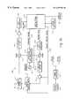
- FIG. 1depicts a block diagram of the major components of the network according to principles of the present invention
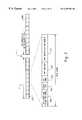
- FIG. 2is a diagram of the structure of the data block according to principles of the present invention.
- FIG. 3 ais a block diagram of a Personal Alarm Device (PAD) according to principles of the present invention
- FIG. 3 bis a pictorial view of one possible embodiment of the Personal Alarm Device (PAD) according to principles of the present invention
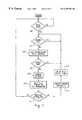
- FIG. 4 ais a flowchart depicting the transmit-only mode of the operation of the Personal Alarm Device (PAD) according to principles of the present invention
- FIG. 4 bis a flowchart depicting the transmit- and receive confirmation mode of the operation of the Personal Alarm Device (PAD) according to principles of the present invention
- FIG. 5is a block diagram of a Proximity Sensing Transceiver (PROX) according to principles of the present invention
- FIG. 6is a block diagram of a Direction Finding Receiver (DFR) according to principles of the present invention.
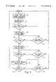
- FIG. 7depicts a flow diagram of the Priority-delay, Persistent-Carrier Sense Multiple Access (PDP-CSMA) technique according to the principles of the present invention.
- PDP-CSMAPersistent-Carrier Sense Multiple Access
- FIG. 8depicts a flow diagram of the Priority-delay, Frequency-Hopped-Carrier Sense Multiple Access (PDFH-CSMA) technique according to principles of the present invention
- FIG. 9depicts a flow diagram of the fast-scan mechanism used by the Tracking System network according to principles of the present invention.
- FIG. 10depicts a time-diagram of the operation of the PDP-CSMA techniques network according to principles of the present invention
- FIG. 11is a block diagram of the Direction-Finding Tracker (DFT) according to principles of the present invention.
- FIG. 12is a block diagram of an alternate embodiment (using signal-strength only) of the Tracker according to principles of the present invention.
- Proximity Receiver Controller Transmitters108 a, 108 b, 108 c, and 108 d, located inside a building 101 , receive RF signals transmitted from a Personal Alarm Device (PAD) 100 b which is also located inside the building 101 .
- PADPersonal Alarm Device
- the PROXs 108 a, 108 b, 108 c, and 108 ddetermine the PAD identity and PAD signal strength, then send this data to a group concentrator 107 which concentrates the data for transmission to a communication hub 109 .
- the communication hub 109routes the data to a Network Management System (NMS) 114 via a wire or wireless link.
- NMSNetwork Management System
- PROXsare advantageously located in the interiors of buildings where the uncertain attenuation and path of a signal makes detection by external receivers difficult. Although preferably used in building interiors, the PROXs may be placed outside of the building 101 , in parking lots, for example.
- PROXsare installed on nearly every floor of a building; the exact number and location of the PROXs depends on the layout and signal propagation properties of a particular building.
- the PROXsprovide estimates of a PAD's signal strength, estimates measured over multiple frequencies used in each transmission from the PAD, as further explained below.
- the estimatesare transmitted to the NMS where the signal strength estimates from all the PROXs receiving the PAD's signal are used in a signal-strength-vs-distance technique, well known in the art, to accurately estimate of the PAD's location.
- the signal strength data received by PROXs 108 a- 108 dis used by the NMS 114 to estimate the PAD's location in the building; this estimated location is then sent by the NMS 114 to Command and Control Centers (CCCs) 112 a and 112 b for display. If the RF signal transmitted by the PAD 100 b leaves the building, then Direction Finding Receivers (DFRs) 102 a , 102 b , 102 c , and 102 d detect the signal and provide location data to a data concentrator 104 which concentrates the data from the various DFRs, then to communication hub 109 which routes the data to the NMS 114 . The NMS 114 uses this data to confirm the in-building location estimate of PAD 100 b.
- DFRsDirection Finding Receivers
- the PAD 100 btransmits frequency-hopped signals which can originate on any of the minimum number of frequency channels required for shared-band use of the spectrum (typically 50 channels). In order to quickly “hear” a transmission, the PROXs and DFRs rapidly scan all of the frequency channels for possible transmissions.
- Another PAD 100 aalso transmitting frequency-hopped signals, is located outside of building 101 , and transmits RF signals to the DFRs 102 a, 102 b, 102 c, and 102 d which rapidly scan a set of frequency-hopped channels for a signal, then estimate the time-of-arrival (TOA), and angle-of-arrival (AOA) of the signal.
- the DRFs 102 a , 102 b , 102 c , and 102 dare preferably located on radio towers and receive signals of PADs located beyond the receiving range of PROXs 108 a- 108 d.
- three to five DFRsare used in a network that covers an area the size of a college campus. Of course, the number of DFRs can be varied to increase or decrease the network coverage area.
- the DFRs 102 a - 102 destimate the TOA and/or AOA of the signal transmitted by the PAD 100 a. Two such estimates of AOA and three of TOA are sufficient to estimate the location of the signal source. However, the quality of the location estimate can be significantly improved when more estimates are available.
- the DFRs 102 a - 102 dare preferably hard-wired to the group concentrator 104 where data is concentrated.
- the group concentrator 104is coupled to communication hub 109 which routes the data to the NMS 114 . Although hard-wiring is preferred, any type of communication link can be used for the connection.
- the DFRs 102 a - 102 ddetermine an identification number of the PAD 100 a, and any additional data from the transmitting device, and an estimate of the absolute signal level.
- the DFRs 102 a - 102 dsend this information to the NMS 114 where the location can be estimated by multiple techniques; e.g. triangulation from the angle-of-arrival (AOA) estimates; the maximum-likely-position based on both absolute and relative signal strength estimates; and multilateration from the time-of-arrival (TOA) estimates from the different DFRs 102 a - 102 d that report an event.
- AOAangle-of-arrival
- TOAtime-of-arrival
- this additional informationis used to increase the accuracy and reliability of the location estimates, by any of a variety of well known location-solution-optimization methods.
- the NMS 114also manages the operations of the network and can be located at a CCC 112 where operations of the network are controlled and monitored.
- Communication links 116couple PROXs 108 a- 108 d to the NMS 114 , and can be point-to-point wireless, power-line communication, or hard-wired links.
- the NMS 114is connected to an ethernet network 113 , and the CCCs 112 a and 112 b are also connected to the ethernet network 113 .
- the CCCs 112 a and 112 bcan be configured as master and slave CCCs and can be located anywhere along the ethernet network 113 .
- the PADs 100 a and 100 bmay be transmit-only devices or, preferably, a two-way, transmit-receive devices. Whereas the transmit only device must rely on some form of external, secondary confirmation of the device's operation, the two-way device provides confirmation of the network operation at the device, in addition to possibility of providing other operational features. All PADs are battery operated with the battery having a long life, preferably, of at least one school year. The PADs batteries are recycled at the end of the school year or after an emergency call to ensure that the PADs are always operational.
- the PADs 100 a and 100 btransmit alarm and confidence-test transmissions.
- the PADcontinuously transmits the signal used to locate the person.
- continuouslyit is meant to include not only unbroken transmissions but also to include short (low duty-cycle) transmissions repeated frequently, which minimize the use of spectrum while still transmitting frequently enough for the personnel, coming to the aid of the caller, to track the signal through the network or with a hand-held tracking device.
- the PADcan also be activated to transmit a much shorter test signal to receive confirmation of the proper operation of the device and the network.
- the duration of an alarmcould be as long as 30 minutes, even at the end of the school year (near the end of the battery's life expectancy).
- the alarm transmissioncarries the PAD identification number and an alarm type opcode.
- a hand-held, signal-strength-only, or, signal-strength and direction-finding tracking device (DFT) 115is used to locate PADs within the area of coverage.
- the DFTis used by the security operator to physically “home-in” on the PAD 100 a transmitting an alarm.
- the confidence-test transmissionis used to confirm the operation of the PAD.
- the confidence test signal transmissionis made for a one-second duration and is transmitted sequentially across ten hopped frequency channels (for multi-path fading diversity and for compliance with the shared band access rules.) Each hop consists of eight repeats of the preamble, op-code, transmission-counters and PAD identification number and checksums. Each time a confidence test signal is initiated, a different set of hopped frequencies are used, so that at least 50 different frequencies are used with about equal probability, as required for shared-band use.
- the confidence-test transmissionscarry the PAD identification number and a confidence-test type opcode.
- Frequency hopping techniquesare used by the network to ameliorate the effects of signal “collisions” which inevitably occur with shared access to a communication band. Therefore, the PADs 100 a and 100 b transmit a narrow-band frequency hopped signal as detailed in FIG. 2.
- a series of data blocks 200 a - 200 jare transmitted at a hop frequency N. After transmitting these data blocks, the hop frequency is changed to hop frequency N+1 after a hop transmission interval.
- the hop transition intervalis less than 1 ms.
- a data blockcomprises a 64-bit preamble 202 a which includes the bit-synch acquired by the system and timing information and may include a Barker code start flag.
- the purpose of the long preamble in the data structureis to provide a repetitive signal on which phase and angle of arrival measurements can be accurately made.
- the data blockalso includes a 8-bit opcode 202 b which indicates the type of transmission.
- the “operation-code type” of transmissionmay, for example, be a confidence test transmission or an alarm transmission, or any other signaling type that may be used by the system, such as message-paging.
- the opcode 202 bis followed by the checksum bit field 202 e which provides for data validity checking by the receiver.
- the checksumis followed by a 16-bit repeat-count and hop-count field 202 c which indicates the next hop frequency and the current repeat count showing the number of blocks transmitted at the current hop frequency.
- the repeat-and-hop field 202 cis followed by 32-bit ID address field 202 d which identifies the PAD sending the message.
- This data-blockwill be repeated multiple (eight) times in each hop transmission burst (the whole hop-dwell time).
- This data structurecan be modified to include changes to the duty-factor of the alarm-call transmission, where either the maximum dwell time can be reduced, while keeping the hop time fixed, or keeping the dwell time and increasing the hop-transition time to multiple hop times in duration.
- One illustrative embodiment of the present invention using the data block structure described aboveprovides a channel bandwidth of 25 kHz, the number of hop channels of at least 50, a maximum dwell time of less than 400 ms, a MSK modulation of 15.625 kBPS, and a user data rate of 15.625 kBPS.
- the series of data blocks transmitted at hop frequency Noccurs for 108.5 ms.
- the transmissionis relatively narrow-band, it is subject to severe multi-path fading indoors.
- the effects of multi-path fadingare greatly ameliorated by the frequency-hopping access technique of the present invention, since it requires transmitting the signal successively on multiple narrow band channels.
- the hop frequenciesare widely spaced in frequency (in accordance with the frequency-hopping requirements) to obtain maximum multi-path diversity.
- a PADcomprises a frequency-hopped spread spectrum transceiver 209 that operates in the 902-928 MHz “Industrial Scientific & Medical” (ISM) band which allows for low-powered spread spectrum communication with minimum licensing requirements.
- ISMInternational Scientific & Medical
- This bandis occupied by a number of services that share the band, under a set of technical-usage/access-rules set by the FCC.
- a digital signal processor (DSP) 210manages all the activities of the transceiver 209 , based on programs stored in a DSP memory 221 .
- the programsimplement the prioritized frequency-hopped CSMA communication protocols, the data coding function, the real-time transceiver control activities and interaction with a key pad and display 211 . Interaction commands received from the key pad and display 211 are converted into transmission or reception actions.
- the DSP 210To transmit a signal, the DSP 210 initializes a synthesized local oscillator 212 , which is supplied by a frequency reference 206 , to the desired hop frequency, as required by the frequency-hopping protocol.
- the DSP 210presents the data to be sent to a modulator 213 , switches a transmit/receive (T/R) switch 214 to a “transmit” position and applies power to a power amplifier 215 .
- the datais mixed with the signal from local oscillator 212 by a mixer 216 , transmitted through a bandpass filter 235 which filters out unwanted signals, and then sent through the amplifier 215 .
- the signalis then transmitted through the T/R switch 214 (which is in the “transmit” position), through a RF bandpass filter 235 which minimizes any unwanted noise or harmonics, and, finally, to an antenna 225 for transmission.
- the miniature antennais sized to transmit and receive signals in the 902-928 MHz band.
- the DSP 210When the DSP 210 requires reception, it routes signals from the antenna 225 , through the filter 217 , through the T/R switch 214 which is set to a “receive” position.
- the transmit receive switch 214is set by DSP 210 via transmit-receive control 205 .
- the RF signalis then mixed down in a double conversion to the desired frequency (typically a 45 MHz and 455 Khz intermediate frequency) at mixer 218 with a signal from the synthesized local oscillator 212 , applied through a IF bandpass filter 219 and limiting-IF-amplifier 219 .
- the signalis then processed by demodulator 222 to yield a 15.625 kBPS data signal.
- the datais then decoded by the DSP 210 , and further action is determined according to the stored programs in the DSP memory 221 .
- the PADderives power from a battery system 223 , which preferably produces an output voltage of 6 volts, and converter 224 and provides interaction with the user through a set of push-buttons and LED indicator lights.
- the transmit power levelis necessarily limited by the small battery and operating time limitations to about 100 milliwatts of output.
- the PAD 236comprises LED light 237 a which indicates that the unit is transmitting and a first push button 238 a and a second push button 238 b.
- the userpresses both buttons simultaneously to send and alarm and one button after another button to initiate a test.
- the PADis small, compact and battery powered.
- the life of the batteryis preferably at least a school year in duration. To achieve such a lifetime, the maximum transmit power of the alarm call device will necessarily be quite limited. However, the signal must be powerful enough to be adequately received at reasonable distances, even inside buildings. With a small lithium battery, a 100 mw transmit level would satisfy the signal-range requirements and make possible confidence testing once a day through-out the school year, and still provide an alarm transmission of 30 minutes duration, even at the end of the school year.
- the PADdetermines at step 252 whether the confidence-test button on the PAD has been pushed. If affirmative, at step 254 , power to the transceiver is turned on. Then, at step 256 , the confidence test opcode is placed in the opcode field of the data block. The PAD's identification number is placed in the identification field at step 258 . Next, the confidence test signal is transmitted at step 260 , according to the prioritized-access method described in this invention. Prior to transmission, the PAD's receiver listens for an absence of other carriers on the transmit channel prior to enabling the transmitter, in accordance with the method of this invention, so avoiding unnecessary signal collisions.
- the PROXreceives, decodes and validates the confidence test transmission, and transmits an acknowledgment signal (ACK) with the PAD's identification number, back to the PAD, on the last frequency channel used by the PAD in its hopping sequence.
- the PAD's receiver“listens” for the ACK signal and displays the result of the test by flashing the test indicator momentarily at step 261 . Then, power to the PAD is turned off at step 272 . Control returns to step 252 and button scanning resumes as described above.
- This access methodprovides a large number of PADs with equal probability of access to the channel, while the prioritizing algorithm of this invention, described below, allows “alarm transmissions” priority over all “confidence-test transmissions.”
- step 252determines whether the alarm button on the PAD has been pressed. If step 262 is negative, the system continues scanning with step 252 . If step 262 is affirmative, control continues with step 264 where power is turned on to the PAD.
- step 266the alarm opcode is placed in the opcode field of the data block.
- step 268the PAD's identification number is placed in the identification field of the data block.
- step 270the PAD transmits the alarm signal (again, according to the prioritized-access method described in this invention,) until the battery is exhausted or until the PAD's transmission is reset. Execution then ends (and, for user confidence, the PAD's batteries must be recycled).
- the operations personnelcan elect to dispatch the nearest security personnel (probably aided by a hand tracking device) to the aid of the caller. This is accomplished through conventional two-way voice communication between personnel at the CCC and emergency personnel as is known to those skilled in the art.
- the PAD transmissionis the same as for the confidence test, but repeats “continuously”, allowing the PROX to hear it at least five times per second.
- This great redundancyallows the possibility of some power saving in the PAD by reducing the duty-cycle of the PAD's alarm transmission by, for example, reducing the number of data-block repetitions per hop, or introducing a delay at the end of each transmission before hopping to the next channel—i.e. increasing the hop-transition interval.
- FIG. 4 bdepicts the operational flow diagram for another possible embodiment of the PAD.
- the PADbehaves the same way as the embodiment depicted in FIG. 4 a, when executing a confidence test transmission, but the alarm test transmission differs in that every alarm transmission burst is acknowledged in the same way that the confidence test transmission is confirmed.
- the PADlistens at step 274 between alarm transmissions, on the last channel used for transmission, for the ACK signal, and when it gets an ACK, flashes the alarm indicator to confirm operation. The process continues again until either the battery is exhausted or the PAD is reset at step 276 .
- a PROXcomprises a frequency-hopped spread spectrum transceiver 309 .
- a digital signal processor (DSP) 310manages all the activities of the transceiver 309 , based on programs stored in a DSP memory 321 .
- the programsimplement the prioritized frequency-hopped CSMA communication protocols, the data coding function, the real-time transceiver control activities and interaction with the user interface which is a serial-line communication processor 311 .
- the serial-line communication processor 311communicates with a serial-line transceiver modem 334 which is coupled to a communication line.
- the DSP 310To transmit a signal, the DSP 310 initializes a synthesized local oscillator 312 to the desired hop frequency via frequency control 304 , as required by the frequency-hopping protocol, presents the data to be sent to a modulator 313 , switches a transmit/receive (T/R) switch 314 to a “transmit” position via a transmit-receive control 305 and applies power to a power amplifier 315 .
- the datais mixed with the signal from local oscillator 312 by a mixer 316 , transmitted through a bandpass filter 317 which minimizes any unwanted noise and harmonics, and then sent through the amplifier 315 .
- the signalthen is then transmitted through the T/R switch 314 (which is in the “transmit” position), through a RF bandpass filter 335 which minimizes any unwanted noise and harmonics, and, finally, to an antenna 325 for transmission.
- the antenna 325transmits and receives signals in the 902-928 MHz band.
- the DSP 310When the DSP 310 requires reception, it routes signals from the antenna 325 through the bandpass filter 317 , then through the T/R switch 314 which is set to a “receive” position via the control 305 .
- the RF signalis mixed down to the desired 45 MHz and 455 Khz intermediate frequencies at a double conversion mixer 318 by a signal from the synthesized local oscillator 312 , applied through a IF bandpass filter 319 and amplifier 320 where the absolute signal-strength is determined by calibrated relative signal strength indicator (RSSI) circuitry 324 and the signal is demodulated at 322 to yield a 15.625 KBPS data signal.
- RSSIcalibrated relative signal strength indicator
- the power of the systemis derived from a DC supply 332 which preferably has an output voltage of 24 volts.
- a power converter 333converts the output voltage of supply to both analog and digital voltages which are used by the various elements in the PROX.
- the transmission-output power levelis limited to less than one watt by the FCC standards for this band.
- Interaction with the networkis via a serial-line communication processor and suitable modem device. Two-way interaction occurs with the networks operations center via the concentrator and network hub.
- a DFRcomprises a frequency-hopped spread spectrum transceiver 409 .
- a digital signal processor (DSP) 410manages all the activities of the transceiver 409 , based on programs stored in a DSP memory 421 .
- the programsimplement the prioritized frequency-hopped CSMA communication protocols, the data coding function, the real-time transceiver control activities and interaction with a serial-line communication processor 411 .
- the serial line communication processor 411communicates with a serial-line transceiver modem 434 which is coupled to a communication line. Interaction commands received from the serial communication processor 411 are converted into transmission or reception actions by the DSP 410 .
- the DSP 410To transmit a signal, the DSP 410 initializes a synthesized local oscillator 412 to the desired hop frequency, as required by the frequency-hopping protocol, presents the data to be sent to a modulator 413 , switches a transmit/receive (T/R) switch 414 to a “transmit” position (via transmit-receive control signal 405 ) and applies power to a power amplifier 415 .
- the modulated signalis up-converted by the signal from local oscillator 412 at mixer 416 , filtered a bandpass filter 417 which minimizes any unwanted noise or harmonics, and then amplified at 415 .
- the signalthen is then switched at the T/R switch 414 (which is in the “transmit” position), through a RF bandpass filter 435 which minimizes any unwanted noise or harmonics, and, finally, to an antenna 425 for transmission. Both antennas operate in the 902-928 MHz band.
- the DSP 410When the DSP 410 requires reception, it routes signals from the antenna 425 b , through antenna array modulator 425 a , RF bandpass filter 417 , through the T/R switch 414 which is set to a “receive” position (via transmit-receive control signal 405 ), the RF signal is mixed down to the desired frequency to yield 45 MHz and 455 Khz intermediate frequencies at double mixer 418 by a signal from the synthesized local oscillator 412 (which is controlled by a frequency reference 406 ), applied through a IF bandpass filter 419 and amplifier 420 where the signal is demodulated by 422 to yield a 15.625 KBPS data signal and detected by RSSI circuitry at 424 to yield a signal strength estimate. The data is then decoded, and signal strength processed by the DSP 410 . Further action is determined according to the stored programs in the DSP memory 421 .
- the modulator 425 a and antenna array 425 b with its accompanying modulator, and complimentary angle of arrival software in the DSPform a pseudo-Doppler direction-finder.
- the modulator 425 ais controlled by a Doppler direct finder modulator control signal 406 from the DSP 410 .
- the signals from the antenna arrayare processed by the DSP 410 .
- the processingextracts data from the signals, determines angle and time of arrival of each significant multi-path arrival and estimates the absolute signal strength. This data is then communicated through the serial-line communication processor 411 , serial-line transceiver 434 , and the NMS via any type of link such as a telephone line, or PTP microwave.
- the transmit functionis used mainly for direction-finder calibration, acknowledgment signals, and network maintenance purposes, and so the transmitter is connected to the transmitter receiver switch 414 .
- a PADinitiates accessing of a communication channel at step 600 , determining whether a data packet is ready to be sent. If negative, control waits by loops back to the same step. If affirmative, at step 602 , the channel is sensed to determine whether it is busy. If the channel is busy, control loops back to step 602 and the channel is sensed until it is idle. However, when step 602 is negative, that is, the channel is idle, the device waits at step 604 for a specific interval (the priority-delay interval) before testing for idle again at step 606 .
- a specific intervalthe priority-delay interval
- step 606finds the channel idle, control continues with step 608 and the message is transmitted. In other words, only if the channel is still idle after the priority-delay interval will the device transmit on the channel.
- the PADtransmits the message.
- the PADwaits till it receives an acknowledgment from the PROX or DFR that the packet has been correctly received, or until the maximum wait time has expired. If a positive ACK has been received by the PAD at step 612 , control returns to step 600 where the PAD waits for the next packet to be sent.
- the access mechanism of FIG. 7uses a single communications channel which, in a shared band, may be occupied by other users or noise.
- Using a frequency-hopped spread spectrum techniqueallows the devices to both avoid signal degradation caused by interference that may already be present on the channel, and to avoid causing interference on a channel that is currently busy.
- step 500the PROX determines whether a packet is ready for transmission. If not, control passes back in a waiting loop to step 500 until a packet is ready.
- step 500is affirmative, the next hop frequency channel is selected at step 502 the PAD and the hop interval timer starts.
- the devicedetermines whether the channel is busy at step 504 . If the channel is busy, the device determines whether the hop timer has expired at step 506 . If the hop timer has expired, then control resumes at step 502 where a new hop channel is selected and the hop interval timer is reset. Thus steps 504 and 506 wait for the channel to become idle for up to one hop time.
- step 504If the answer to step 504 is negative (channel idle), then the device waits for a prioritizing delay interval before proceeding at step 508 . After this delay, at step 510 , the device again determines whether the channel is busy. If the answer to step 510 is affirmative (channel became busy during the wait), control returns to step 506 . However, if the channel is still idle at step 510 , control proceeds with step 512 where the message is transmitted. Next, at step 514 , the device waits until it receives an ACK or until the maximum wait period times out. At step 516 , the device determines whether an ACK has been received. If the answer to step 516 is positive, control proceeds to step 518 where a “OK” indicator is flashed on the PAD.
- controlreturns to step 500 . If the answer at step 516 is negative, then step 520 re-transmission is attempted. Next, at step 522 , a random variable k is computed. Then, at step 524 , the device waits for a delay of k milliseconds. Finally, control returns to step 502 .
- Obvious variants of this schemeinclude that the there may be separate timers for hop interval (hop dwell time) and busy-channel time-out.
- the scanning processbegins at step 700 where the system measures the received signal strength indication (RS SI) on the next frequency hop channel.
- RS SIreceived signal strength indication
- the systemdetermines whether the RSSI is above a threshold. If the answer is negative (implying an empty channel), the system returns to step 700 to hop to the next frequency. If the answer to step 704 is affirmative, then at step 706 the bit-synch time out timer is started.
- step 708the system determines whether bit-synch has been detected. If the answer to step 708 is negative (implying noise or incompatible signal modulation in the channel), then at step 710 the device determines if the bit-synch timer has expired. If the answer to step 710 is affirmative, then the system returns to step 700 . On the other hand, if the answer at step 710 is negative, then the system returns to step 708 , attempting to detect bit-synch till the bit-synch timer expires.
- step 708the system starts the data read time-out timer at step 712 .
- step 714the device determines whether the decoded data is identifiable. If the answer at step 714 is negative, then, at step 716 , the system determines whether the data-read time-out timer has expired. If the answer is affirmative, control returns to step 700 . If the answer is negative, then control returns to step 714 where identifiable data is searched for until the data-timer expires.
- step 718the device scans to the end of the preamble in the data block and reads the data.
- step 720the device determines whether the CRC contained in the data block validates the data. If the answer is affirmative, control returns to step 700 . If the answer is negative, then at step 722 , the device decides whether a terminal repeat count exists. If the answer at step 722 is negative, then control returns to step 718 where the data is re-read. On the other hand, if the answer to at step 722 is affirmative, then control returns to step 700 .
- the dwell timeis very short—typically less than a millisecond.
- bit synch obtainedbetween 10 and 15 milliseconds are required to properly decode the data, depending on when in the PAD transmission the PROX arrives on-channel. Therefore, even under the worst case load on the system, the PROX will have at least five opportunities to detect the confidence test transmission from any particular nearby PAD.
- One result of using the access control mechanism of this inventionis that all currently active system transmissions in a locality will tend to become accurately “serialized”, avoiding collisions, and allowing the scanning operation of the PROX to accurately decode the data from the PAD's transmission. Also, allowing the PAD to “listen” for a significant interval (a few seconds) for an ACK from the PROX, allows the PROX to use the same access control mechanism and similar data structure to transmit the ACK to the PAD with a very low probability of signal loss due to collision with any interfering signals.
- the NMScoordinates operations in the network and can be located at the CCC.
- the NMScommunicates with the PROXs located in all the campus buildings, and the DFRs.
- the NMScomputes the estimated location of an alarm transmission (based on either the signal amplitude information from multiple PROX devices, or from the TOA or AOA information from the DFRs) and communicates that to the CCC.
- the NMSalso keeps track of the system's performance and responds to commands and requests from the command and control center. Additionally, the NMS manages the moment-to-moment operation of the network.
- the NMScan be located with the CCC or at any remote location
- the NMSalso maintains all the data bases for the network's operation, such as for subscriber records.
- the CCCmanages logistics of the network. Any and all of the information gathered by the NMS can be accessed and displayed at the command and control center.
- the NMSholds all network infrastructure databases while the CCC holds all user databases. This includes the location of any active alarms.
- the CCCdisplays the location of the PAD sending the alarm signal.
- the CCCkeeps a log of all the PADs performing confidence tests, logging the time and date of each test, as well as the estimated location quality information. Maintenance of the network's data bases are also performed from the CCC.
- the timeline of the operation of the systemis illustrated.
- the receivers in the PROXs and DFRssense the channel for traffic during time window 801 a occurring between times t 0 to t 1 .
- Transmissions with the highest prioritybegin during time windows 802 a and 802 b ; transmissions with medium priority occur during time windows 804 a and 804 b; and transmissions with the lowest priority are initiated during time windows 806 a and 806 b .
- the highest priority transmissionsare alarm calls; medium priority transmissions include confidence tests; and low priority transmissions include the sending of telemetry or paging data.
- any number of priority classesmay be used.
- a devicewaits for a random delay time before beginning a transmission. For example, a transmission with a high priority waits for a random time period d 1 in time window 802 a before beginning a transmission at time t 1 . Then the transmission by a PAD of the high priority transmission occurs during time window 808 between times t 1 , and t 2 At time t 2 , the PROXs and DFRs begin sensing the signal traffic on the channel again.
- the DFRs and PROXssense the channel's signal traffic in time window 801 b between times t 2 and t 3 .
- a medium priority transmissionis initiated during time window 804 b.
- the transmissionoccurs during time window 810 between time t 3 and time t 4 .
- a DFTcomprises a digital signal processor (DSP) 910 which manages all the activities of the transceiver 909 , based on programs stored in a DSP memory 921 .
- the programsimplement the prioritized frequency-hopped CSMA communication protocols, the data coding function, the real-time transceiver control activities and interaction with a tracker display and control panel 911 . Interaction commands received from the tracker display and control panel 911 are converted into transmission or reception actions by the DSP 910 .
- the DSP 910To transmit a signal, the DSP 910 initializes a synthesized local oscillator 912 to the desired hop frequency, as required by the frequency-hopping protocol, presents the data to be sent to a modulator 913 , switches a transmit/receive (T/R) switch 914 to a “transmit” position (via transmit-receive control signal 905 ) and applies power to a power amplifier 915 .
- the datais mixed with the signal from local oscillator 912 by a mixer 916 , transmitted through a bandpass filter 935 which filters out unwanted signals, and then sent through the amplifier 915 .
- the signalthen is then transmitted to an antenna 925 c for transmission. Both antennas operate in the 902-928 MHz band.
- the DSP 910When the DSP 910 requires reception, it routes signals from the antenna 925 b , through antenna array modulator 925 a, RF bandpass filter 917 , through the T/R switch 914 which is set to a “receive” position (via transmit-receive control signal 905 ), the RF signal is mixed down to the desired intermediate frequencies of 45 MHz and 455 Khz at double mixer 918 by a signal from the synthesized local oscillator 912 (which is supplied with a frequency reference 906 ), applied through a IF bandpass filter 919 and amplifier 920 , where the signal absolute signal strength is estimated by calibrated RSSI circuitry, and on to the demodulator 922 where it is processed to yield a 15.625 KBPS data signal. The data is then decoded by the DSP 910 , and further action is determined according to the stored programs in the DSP memory 921 .
- the antenna 925 b and its accompanying modulator 925 ais a pseudo-Doppler direction-finder antenna array with complimentary control and angle of arrival software in the DSP.
- the transmit functionis used only for direction-finder calibration and network interaction purposes, and so the transmitter is connected to the transmitter receiver switch 914 .
- the modulator 925 ais controlled by a Doppler direct finder modulator control signal 906 from the DSP 910 .
- a front-to-back ratiocan be derived and used to determine location.
- a DFTcomprises a digital signal processor (DSP) 1010 which manages all the activities of the transceiver 1009 , based on programs stored in a DSP memory 1021 .
- the programsimplement the prioritized frequency-hopped CSMA communication protocols, the data coding function, the real-time transceiver control activities and interaction with a tracker display and control panel 1011 .
- Interaction commands received from the tracker display and control panel 1011are converted into transmission or reception actions by the DSP 1010 .
- the DSP 1010To transmit a signal, the DSP 1010 initializes a synthesized local oscillator 1012 to the desired hop frequency, as required by the frequency-hopping protocol, presents the data to be sent to a modulator 1013 , switches a transmit/receive (T/R) switch 1014 to a “transmit” position (via transmit-receive control signal 1005 ) and applies power to a power amplifier 1015 .
- the datais mixed with the signal from local oscillator 1012 by a mixer 1016 , transmitted through a bandpass filter 1035 which filters out unwanted signals, and then sent through the amplifier 1015 .
- the signalthen is then transmitted through the T/R switch 1014 (which is in the “transmit” position), through a RF bandpass filter 1017 which deletes any unwanted noise, and, finally, to an antenna 1025 for transmission.
- the antennatransmits and receives signals in the 902-928 MHz band.
- the DSP 1010When the DSP 1010 requires reception, it routes signals from the antenna 1025 b , through antenna 1025 , RF bandpass filter 1017 , through the T/R switch 1014 which is set to a “receive” position (via transmit-receive control signal 1005 ), the RF signal is mixed down to a 45 MHz and 455 Khz intermediate frequencies at double mixer 1018 by a signal from the synthesized local oscillator 1012 (which is supplied with a frequency reference 1006 ), applied through a IF bandpass filter 1019 and amplifier 1020 , where the signal absolute signal strength is estimated by calibrated RSSI circuitry, and on to the demodulator 1022 where it is processed to yield a 15.625 kBPS data signal. The data is then decoded and the signal strength estimates processed by the DSP 1010 , and further action, such as information display and control panel interaction, is determined according to the stored programs in the DSP memory 1021 .
- a low interference-potential mechanism for multiple access by unsynchronized locator-transceivers using the frequency hopping techniques required for band-useis provided. Interference is significantly reduced while operating in the ISM band, which enhances communication reliability.
- a reliable spread-spectrum signaling techniqueis provided for tracking the location of the transceiver with a simple mechanism for prioritizing access of different classes of transmission. The system quickly and reliably locates people using the radio-transceiver and allows security personnel to quickly come to the aid of people who experience a threat to their personal safety anywhere in or near a campus or similar environment.
- a deviceis provided which transmits an identification signal that can be remotely located and tracked with enough precision for security personnel to quickly come to their aid.
- the systemis reliable, robust, and user-friendly and offers an on-demand confidence-test feature. Interference is effectively managed or controlled or avoided, thereby ensuring communications-reliability, while still maximizing the throughput of the system which uses of a number of different wireless locating technologies and shared transmission bands.
Landscapes
- Engineering & Computer Science (AREA)
- General Physics & Mathematics (AREA)
- Physics & Mathematics (AREA)
- Business, Economics & Management (AREA)
- Emergency Management (AREA)
- Radar, Positioning & Navigation (AREA)
- Computer Security & Cryptography (AREA)
- Remote Sensing (AREA)
- Computer Networks & Wireless Communication (AREA)
- Signal Processing (AREA)
- Mobile Radio Communication Systems (AREA)
- Small-Scale Networks (AREA)
- Alarm Systems (AREA)
Abstract
Description
Claims (14)
Priority Applications (8)
| Application Number | Priority Date | Filing Date | Title |
|---|---|---|---|
| US08/910,066US6459704B1 (en) | 1997-08-12 | 1997-08-12 | Method and system for radio-location determination |
| IL12567598AIL125675A0 (en) | 1997-08-12 | 1998-08-05 | A method and system for radio-location determination |
| AU78798/98AAU751604B2 (en) | 1997-08-12 | 1998-08-05 | A method and system for radio-location determination |
| EP98114835AEP0897233A3 (en) | 1997-08-12 | 1998-08-06 | A method and system for radio-location determination |
| CA002244583ACA2244583C (en) | 1997-08-12 | 1998-08-07 | Frequency-hopping spread-spectrum radio communications |
| CA002450503ACA2450503A1 (en) | 1997-08-12 | 1998-08-10 | Frequency hopping spread-spectrum radio communications |
| JP10228083AJPH11168478A (en) | 1997-08-12 | 1998-08-12 | Method for determining radio position and its system |
| US10/092,327US20020131393A1 (en) | 1997-08-12 | 2002-03-06 | Graphic user interface for a radio location determination system |
Applications Claiming Priority (1)
| Application Number | Priority Date | Filing Date | Title |
|---|---|---|---|
| US08/910,066US6459704B1 (en) | 1997-08-12 | 1997-08-12 | Method and system for radio-location determination |
Related Child Applications (1)
| Application Number | Title | Priority Date | Filing Date |
|---|---|---|---|
| US23590099AContinuation-In-Part | 1997-08-12 | 1999-01-22 |
Publications (1)
| Publication Number | Publication Date |
|---|---|
| US6459704B1true US6459704B1 (en) | 2002-10-01 |
Family
ID=25428264
Family Applications (1)
| Application Number | Title | Priority Date | Filing Date |
|---|---|---|---|
| US08/910,066Expired - LifetimeUS6459704B1 (en) | 1997-08-12 | 1997-08-12 | Method and system for radio-location determination |
Country Status (6)
| Country | Link |
|---|---|
| US (1) | US6459704B1 (en) |
| EP (1) | EP0897233A3 (en) |
| JP (1) | JPH11168478A (en) |
| AU (1) | AU751604B2 (en) |
| CA (1) | CA2244583C (en) |
| IL (1) | IL125675A0 (en) |
Cited By (22)
| Publication number | Priority date | Publication date | Assignee | Title |
|---|---|---|---|---|
| US20020098852A1 (en)* | 2000-11-14 | 2002-07-25 | Goren David P. | Methods and apparatus for identifying as set location in communication networks |
| US20030096576A1 (en)* | 2000-12-29 | 2003-05-22 | Theodoros Salonidis | Method and apparatus for connecting devices via an ad hoc wireless communication network |
| US20030145100A1 (en)* | 2002-01-31 | 2003-07-31 | The Fantastic Corporation | Method and system of data packet transmission timing for controlling bandwidth |
| US6657549B1 (en)* | 1999-08-05 | 2003-12-02 | Koninklijke Philips Electronics N.V. | Location finding system and method |
| US6690263B1 (en) | 1998-01-15 | 2004-02-10 | Innovatron Electronique | Method of managing collisions in a non-contact data interchange system |
| US6763315B2 (en)* | 2000-11-29 | 2004-07-13 | Ensure Technologies, Inc. | Method of securing access to a user having an enhanced security proximity token |
| US20040143730A1 (en)* | 2001-06-15 | 2004-07-22 | Wu Wen | Universal secure messaging for remote security tokens |
| US20040192316A1 (en)* | 2001-01-30 | 2004-09-30 | Ulrich Botzel | Frequency scheme for data transmission systems |
| US20040207523A1 (en)* | 2003-04-18 | 2004-10-21 | Sa Corporation, A Texas Corporation | Integrated campus monitoring and response system |
| US20040252682A1 (en)* | 2001-09-26 | 2004-12-16 | Siemens Aktiengesellschaft | Method of arbitrating access to a data bus |
| US20050024201A1 (en)* | 2003-08-01 | 2005-02-03 | Spectrum Tracking Systems, Inc. | Method for locating an asset |
| US20050024202A1 (en)* | 2003-08-01 | 2005-02-03 | Spectrum Tracking Systems, Inc. | System for tracking and locating an object using a cellular network |
| US6870809B1 (en)* | 1999-10-08 | 2005-03-22 | Microsoft Corporation | Fair scheduling in broadcast environments |
| US20050073459A1 (en)* | 2003-10-01 | 2005-04-07 | Spectrum5, Inc. | Method and system for time difference of arrival (TDOA) location services |
| US20050157734A1 (en)* | 2003-08-08 | 2005-07-21 | Qinghua Li | Variable SDMA ACK timeout |
| US20050249265A1 (en)* | 2002-09-12 | 2005-11-10 | Yozo Shoji | Method and system for frequency hopping radio communication |
| US7050509B2 (en)* | 1997-04-22 | 2006-05-23 | Silicon Laboratories Inc. | Digital isolation system with hybrid circuit in ADC calibration loop |
| US20080089521A1 (en)* | 2003-04-29 | 2008-04-17 | Eric Le Saint | Universal secure messaging for cryptographic modules |
| US20100061256A1 (en)* | 2006-05-25 | 2010-03-11 | Agency For Science, Technology And Research | Methods of Determining Whether a Frequency Channel is Available for Data Transmission for a Communication Device |
| US8045655B2 (en) | 2005-11-03 | 2011-10-25 | Samsung Electronics Co., Ltd. | Apparatus and method for signal detection in a cognitive radio-based wireless communication system |
| US20150346333A1 (en)* | 2014-05-30 | 2015-12-03 | The Boeing Company | Positioning in Indoor Locations and Other GPS-Denied Environments |
| USRE46501E1 (en)* | 1999-02-25 | 2017-08-01 | Microsoft Technology Licensing, Llc | Using a derived table of signal strength data to locate and track a user in a wireless network |
Families Citing this family (20)
| Publication number | Priority date | Publication date | Assignee | Title |
|---|---|---|---|---|
| KR100541947B1 (en) | 2001-05-12 | 2006-01-10 | 삼성전자주식회사 | Wireless communication method and apparatus for avoiding mutual interference between wireless communication systems |
| US7139722B2 (en) | 2001-06-27 | 2006-11-21 | Bellsouth Intellectual Property Corporation | Location and time sensitive wireless calendaring |
| EP1464295A3 (en) | 2003-04-01 | 2006-04-26 | Zimmer GmbH | Implant |
| RU2265250C1 (en)* | 2004-12-24 | 2005-11-27 | Общество с ограниченной ответственностью "АЛЬТОНИКА" (ООО "АЛЬТОНИКА") | Method for transferring notifications when guarding a group of objects |
| RU2278415C1 (en)* | 2005-07-19 | 2006-06-20 | Общество с ограниченной ответственностью "АЛЬТОНИКА" (ООО "АЛЬТОНИКА") | Method for radio communication between protected objects and centralized guard station |
| US7941133B2 (en) | 2007-02-14 | 2011-05-10 | At&T Intellectual Property I, L.P. | Methods, systems, and computer program products for schedule management based on locations of wireless devices |
| US8639267B2 (en) | 2008-03-14 | 2014-01-28 | William J. Johnson | System and method for location based exchanges of data facilitating distributed locational applications |
| US8761751B2 (en) | 2008-03-14 | 2014-06-24 | William J. Johnson | System and method for targeting data processing system(s) with data |
| US8634796B2 (en) | 2008-03-14 | 2014-01-21 | William J. Johnson | System and method for location based exchanges of data facilitating distributed location applications |
| US8600341B2 (en) | 2008-03-14 | 2013-12-03 | William J. Johnson | System and method for location based exchanges of data facilitating distributed locational applications |
| US8566839B2 (en) | 2008-03-14 | 2013-10-22 | William J. Johnson | System and method for automated content presentation objects |
| JP5539364B2 (en)* | 2008-09-29 | 2014-07-02 | コーニンクレッカ フィリップス エヌ ヴェ | Cognitive radio device and method for determining channel occupancy |
| US20100148932A1 (en)* | 2008-12-17 | 2010-06-17 | Sensormatic Electronics Corporation | Wireless electronic article surveillance synchronization system and method with data transfer |
| US8897741B2 (en) | 2009-11-13 | 2014-11-25 | William J. Johnson | System and method for mobile device usability by locational conditions |
| DE102011080107A1 (en)* | 2010-08-05 | 2012-02-09 | Continental Teves Ag & Co. Ohg | Method and system for providing recovery-relevant information |
| EP2823413A4 (en) | 2012-03-07 | 2016-05-04 | Snap Trends Inc | Methods and systems of aggregating information of social networks based on geographical locations via a network |
| EP2891372B1 (en)* | 2012-08-31 | 2017-06-28 | Nokia Technologies OY | Positioning devices |
| US9477991B2 (en) | 2013-08-27 | 2016-10-25 | Snap Trends, Inc. | Methods and systems of aggregating information of geographic context regions of social networks based on geographical locations via a network |
| US9894489B2 (en) | 2013-09-30 | 2018-02-13 | William J. Johnson | System and method for situational proximity observation alerting privileged recipients |
| US10785806B2 (en) | 2017-05-19 | 2020-09-22 | Qualcomm Incorporated | On-demand interference management |
Citations (74)
| Publication number | Priority date | Publication date | Assignee | Title |
|---|---|---|---|---|
| US2298840A (en) | 1938-03-04 | 1942-10-13 | American District Telegraph Co | Alarm system |
| US3573620A (en) | 1967-05-31 | 1971-04-06 | John Raymond Ashley | Security system with inductive to rf communications links |
| US3810161A (en)* | 1973-03-15 | 1974-05-07 | Westinghouse Electric Corp | Apparatus for receiving a frequency and phase coded vehicle control signal |
| US3833895A (en) | 1972-12-29 | 1974-09-03 | D Fecteau | Intrusion alarm with indication of prior activation |
| US3848231A (en) | 1970-12-31 | 1974-11-12 | Baldwin Electronics Inc | Alarm system utilizing pulse position modulation and dual conductor sensor |
| US3914692A (en) | 1973-08-29 | 1975-10-21 | Jr George C Seaborn | Emergency communication system |
| US3925763A (en) | 1973-09-13 | 1975-12-09 | Romesh Tekchand Wadhwani | Security system |
| US4034376A (en)* | 1975-07-24 | 1977-07-05 | International Standard Electric Corporation | Radio direction finder with array element signal processing |
| FR2433795A1 (en) | 1978-08-17 | 1980-03-14 | Elimex Sa | Monitor for route of surveillance personnel - uses portable set with coded transmissions for movement and position detectors which communicate with central monitor |
| US4334221A (en) | 1979-10-22 | 1982-06-08 | Ideal Toy Corporation | Multi-vehicle multi-controller radio remote control system |
| US4367458A (en) | 1980-08-29 | 1983-01-04 | Ultrak Inc. | Supervised wireless security system |
| US4396910A (en) | 1980-05-02 | 1983-08-02 | American District Telegraph Company | Coded security switch |
| US4409592A (en) | 1981-04-20 | 1983-10-11 | Hunt V Bruce | Multipoint packet data communication system using random access and collision detection techniques |
| US4468656A (en) | 1981-06-24 | 1984-08-28 | Clifford Thomas J | Emergency signalling unit and alarm system for rescuing endangered workers |
| US4523184A (en) | 1982-09-30 | 1985-06-11 | Sentrol, Inc. | Supervised wireless security system |
| US4611198A (en) | 1985-09-19 | 1986-09-09 | Levinson Samuel H | Security and communication system |
| US4622538A (en) | 1984-07-18 | 1986-11-11 | Otis Elevator Company | Remote monitoring system state machine and method |
| US4630035A (en) | 1985-01-04 | 1986-12-16 | Motorola, Inc. | Alarm system having alarm transmitter indentification codes and acoustic ranging |
| US4670906A (en)* | 1986-04-02 | 1987-06-02 | Motorola, Inc. | Data communications system transmitter selection method and apparatus |
| US4670739A (en) | 1984-12-14 | 1987-06-02 | Kelly Jr Lawrence R | Communication system especially useful as an incident location reporting security system |
| US4672654A (en) | 1984-12-12 | 1987-06-09 | At&T Company | PBX security system for monitoring security guard tours |
| US4694282A (en) | 1985-01-31 | 1987-09-15 | Kabushiki Kaisha Toshiba | Security monitoring system |
| US4750147A (en) | 1985-11-06 | 1988-06-07 | Stanford University | Method for estimating signal source locations and signal parameters using an array of signal sensor pairs |
| US4764757A (en) | 1987-03-12 | 1988-08-16 | Demarco Frank G | Security detection and location system with independent local alarm and communications circuits |
| US4797948A (en)* | 1987-07-22 | 1989-01-10 | Motorola, Inc. | Vehicle identification technique for vehicle monitoring system employing RF communication |
| US4806938A (en) | 1984-11-20 | 1989-02-21 | Raytheon Company | Integrated self-adaptive array repeater and electronically steered directional transponder |
| EP0314217A2 (en) | 1987-10-30 | 1989-05-03 | Koninklijke Philips Electronics N.V. | Controlled CSMA packet switching system |
| US4868885A (en)* | 1986-05-05 | 1989-09-19 | General Electric Company | Apparatus and method for high-speed determination of received RF signal strength indicator |
| US4876549A (en) | 1988-03-07 | 1989-10-24 | E-Systems, Inc. | Discrete fourier transform direction finding apparatus |
| US4884060A (en) | 1988-12-27 | 1989-11-28 | Lifeline Systems, Inc. | Multi-state selection switch for a personal emergency response system |
| US4908602A (en) | 1989-03-31 | 1990-03-13 | Lifeline Systems, Inc. | Apparatus and method of testing a portable held button for emergency response system |
| US4952928A (en) | 1988-08-29 | 1990-08-28 | B. I. Incorporated | Adaptable electronic monitoring and identification system |
| US4965732A (en) | 1985-11-06 | 1990-10-23 | The Board Of Trustees Of The Leland Stanford Junior University | Methods and arrangements for signal reception and parameter estimation |
| US4990892A (en) | 1989-08-07 | 1991-02-05 | Westcom, A Division Of Westside Communications Of Jacksonville, Inc. | Personnel locator system |
| US4998095A (en) | 1989-10-19 | 1991-03-05 | Specific Cruise Systems, Inc. | Emergency transmitter system |
| US5051741A (en) | 1990-03-28 | 1991-09-24 | Wesby Philip B | Locating system |
| US5055851A (en) | 1988-05-16 | 1991-10-08 | Trackmobile, Inc. | Vehicle location system |
| US5115224A (en) | 1991-07-05 | 1992-05-19 | Detection Systems, Inc. | Personal security system network |
| US5115223A (en) | 1990-09-20 | 1992-05-19 | Moody Thomas O | Personnel location monitoring system and method |
| US5150310A (en)* | 1989-08-30 | 1992-09-22 | Consolve, Inc. | Method and apparatus for position detection |
| US5223816A (en) | 1992-01-17 | 1993-06-29 | Levinson Samuel H | Security and communication system with location detection |
| US5229993A (en) | 1991-02-25 | 1993-07-20 | Old Dominion University | Control of access through local carrier sensing for high data rate networks and control of access of synchronous messages through circulating reservation packets |
| JPH05304514A (en) | 1992-04-24 | 1993-11-16 | Clarion Co Ltd | Spread spectrum communication equipment |
| WO1994009568A1 (en) | 1992-10-09 | 1994-04-28 | E-Systems, Inc. | Adaptive co-channel interference reduction system for cellular telephone central base stations |
| US5317323A (en) | 1993-03-05 | 1994-05-31 | E-Systems, Inc. | Passive high accuracy geolocation system and method |
| US5365217A (en) | 1992-02-20 | 1994-11-15 | Frank J. Toner | Personal security system apparatus and method |
| WO1995001020A1 (en) | 1993-06-25 | 1995-01-05 | Xircom, Incorporated | Virtual carrier detection for wireless local area network with distributed control |
| US5394433A (en)* | 1993-04-22 | 1995-02-28 | International Business Machines Corporation | Frequency hopping pattern assignment and control in multiple autonomous collocated radio networks |
| US5416468A (en) | 1993-10-29 | 1995-05-16 | Motorola, Inc. | Two-tiered system and method for remote monitoring |
| US5416466A (en) | 1994-02-18 | 1995-05-16 | Detection Systems, Inc. | Personal security system with fixed testing transmitters |
| JPH07154297A (en) | 1993-11-30 | 1995-06-16 | Fuji Xerox Co Ltd | Spread spectrum transmitter |
| US5434787A (en)* | 1991-04-12 | 1995-07-18 | Sharp Kabushiki Kaisha | System for measuring position by using global positioning system and receiver for global position system |
| US5444450A (en)* | 1993-08-11 | 1995-08-22 | Motorola, Inc. | Radio telecommunications system and method with adaptive location determination convergence |
| US5467074A (en) | 1992-12-18 | 1995-11-14 | Detection Systems, Inc. | Personal security system with transmitter test mode |
| US5471469A (en)* | 1994-02-08 | 1995-11-28 | Metricon, Inc. | Method of resolving media contention in radio communication links |
| WO1996004717A1 (en) | 1994-08-01 | 1996-02-15 | Arraycomm, Inc. | Spectrally efficient and high capacity acknowledgment radio paging system |
| US5533025A (en)* | 1994-09-26 | 1996-07-02 | International Business Machines Corporation | Robust frequency management and acquisition in a wireless local area network that uses frequency-hopping radios |
| WO1996022662A1 (en) | 1995-01-20 | 1996-07-25 | Arraycomm, Inc. | Spectrally efficient high capacity wireless communication systems |
| US5546090A (en) | 1991-12-12 | 1996-08-13 | Arraycomm, Inc. | Method and apparatus for calibrating antenna arrays |
| US5572192A (en) | 1994-03-17 | 1996-11-05 | Detection Systems, Inc. | Personal security system with guard tour features |
| US5617100A (en)* | 1994-04-07 | 1997-04-01 | Matsushita Electric Industrial Co., Ltd. | Accurate position measuring system |
| US5629707A (en)* | 1995-01-06 | 1997-05-13 | Motorola, Inc. | Flexible signal source location apparatus and method therefor |
| US5719882A (en)* | 1992-04-28 | 1998-02-17 | Hewlett-Packard Company | Reliable datagram packet delivery for simple network management protocol (SNMP) |
| US5852723A (en)* | 1996-08-06 | 1998-12-22 | Advanced Micro Devices, Inc. | Method and apparatus for prioritizing traffic in half-duplex networks |
| US5870426A (en)* | 1992-08-20 | 1999-02-09 | Nexus 1994 Limited | Grouping of spread spectrum acknowledgement pagers to minimize transmission collisions |
| US5875184A (en)* | 1996-12-12 | 1999-02-23 | Altvater Air Data Systems Gmbh & Co.Kg | Method for transferring data packets |
| US5912918A (en)* | 1996-10-10 | 1999-06-15 | International Business Machines Corporation | Method and an apparatus for attachment of a remote station to a base station in a multicellular communications network |
| US5963560A (en)* | 1997-03-05 | 1999-10-05 | Advanced Micro Devices, Inc. | Method and arrangement for providing multi-level priority in a rotating priority arrangement for access to medium in an ethernet network |
| US5966375A (en)* | 1994-06-20 | 1999-10-12 | Canon Kabushiki Kaisha | Method and apparatus for radio communication with control according to priority of data to be transmitted |
| US5999126A (en)* | 1996-08-06 | 1999-12-07 | Sony Corporation | Position measuring apparatus, position measuring method, navigation apparatus, navigation method, information service method, automotive vehicle, and audio information transmitting and receiving method |
| US6006096A (en)* | 1996-11-20 | 1999-12-21 | Aironet Wireless Communications, Inc. | Power based locator system |
| US6088591A (en)* | 1996-06-28 | 2000-07-11 | Aironet Wireless Communications, Inc. | Cellular system hand-off protocol |
| US6157616A (en)* | 1996-05-31 | 2000-12-05 | Lucent Technologies | Adaptive methods for packet transmission over wireless networks |
| US6292508B1 (en)* | 1994-03-03 | 2001-09-18 | Proxim, Inc. | Method and apparatus for managing power in a frequency hopping medium access control protocol |
Family Cites Families (5)
| Publication number | Priority date | Publication date | Assignee | Title |
|---|---|---|---|---|
| US4494119A (en)* | 1983-08-04 | 1985-01-15 | 122923 Canada Limited | Distress radiolocation method and system |
| US5029183A (en)* | 1989-06-29 | 1991-07-02 | Symbol Technologies, Inc. | Packet data communication network |
| US5528621A (en)* | 1989-06-29 | 1996-06-18 | Symbol Technologies, Inc. | Packet data communication system |
| US5596330A (en)* | 1992-10-15 | 1997-01-21 | Nexus Telecommunication Systems Ltd. | Differential ranging for a frequency-hopped remote position determination system |
| CA2103135C (en)* | 1993-11-15 | 1999-05-11 | Lee F. Hartley | Predictive collision avoidance method and apparatus for wireless communications |
- 1997
- 1997-08-12USUS08/910,066patent/US6459704B1/ennot_activeExpired - Lifetime
- 1998
- 1998-08-05AUAU78798/98Apatent/AU751604B2/ennot_activeCeased
- 1998-08-05ILIL12567598Apatent/IL125675A0/ennot_activeIP Right Cessation
- 1998-08-06EPEP98114835Apatent/EP0897233A3/ennot_activeWithdrawn
- 1998-08-07CACA002244583Apatent/CA2244583C/ennot_activeExpired - Fee Related
- 1998-08-12JPJP10228083Apatent/JPH11168478A/enactivePending
Patent Citations (75)
| Publication number | Priority date | Publication date | Assignee | Title |
|---|---|---|---|---|
| US2298840A (en) | 1938-03-04 | 1942-10-13 | American District Telegraph Co | Alarm system |
| US3573620A (en) | 1967-05-31 | 1971-04-06 | John Raymond Ashley | Security system with inductive to rf communications links |
| US3848231A (en) | 1970-12-31 | 1974-11-12 | Baldwin Electronics Inc | Alarm system utilizing pulse position modulation and dual conductor sensor |
| US3833895A (en) | 1972-12-29 | 1974-09-03 | D Fecteau | Intrusion alarm with indication of prior activation |
| US3810161A (en)* | 1973-03-15 | 1974-05-07 | Westinghouse Electric Corp | Apparatus for receiving a frequency and phase coded vehicle control signal |
| US3914692A (en) | 1973-08-29 | 1975-10-21 | Jr George C Seaborn | Emergency communication system |
| US3925763A (en) | 1973-09-13 | 1975-12-09 | Romesh Tekchand Wadhwani | Security system |
| US4034376A (en)* | 1975-07-24 | 1977-07-05 | International Standard Electric Corporation | Radio direction finder with array element signal processing |
| FR2433795A1 (en) | 1978-08-17 | 1980-03-14 | Elimex Sa | Monitor for route of surveillance personnel - uses portable set with coded transmissions for movement and position detectors which communicate with central monitor |
| US4334221A (en) | 1979-10-22 | 1982-06-08 | Ideal Toy Corporation | Multi-vehicle multi-controller radio remote control system |
| US4396910A (en) | 1980-05-02 | 1983-08-02 | American District Telegraph Company | Coded security switch |
| US4367458A (en) | 1980-08-29 | 1983-01-04 | Ultrak Inc. | Supervised wireless security system |
| US4409592A (en) | 1981-04-20 | 1983-10-11 | Hunt V Bruce | Multipoint packet data communication system using random access and collision detection techniques |
| US4468656A (en) | 1981-06-24 | 1984-08-28 | Clifford Thomas J | Emergency signalling unit and alarm system for rescuing endangered workers |
| US4523184A (en) | 1982-09-30 | 1985-06-11 | Sentrol, Inc. | Supervised wireless security system |
| US4622538A (en) | 1984-07-18 | 1986-11-11 | Otis Elevator Company | Remote monitoring system state machine and method |
| US4806938A (en) | 1984-11-20 | 1989-02-21 | Raytheon Company | Integrated self-adaptive array repeater and electronically steered directional transponder |
| US4672654A (en) | 1984-12-12 | 1987-06-09 | At&T Company | PBX security system for monitoring security guard tours |
| US4670739A (en) | 1984-12-14 | 1987-06-02 | Kelly Jr Lawrence R | Communication system especially useful as an incident location reporting security system |
| US4630035A (en) | 1985-01-04 | 1986-12-16 | Motorola, Inc. | Alarm system having alarm transmitter indentification codes and acoustic ranging |
| US4694282A (en) | 1985-01-31 | 1987-09-15 | Kabushiki Kaisha Toshiba | Security monitoring system |
| US4611198A (en) | 1985-09-19 | 1986-09-09 | Levinson Samuel H | Security and communication system |
| US4750147A (en) | 1985-11-06 | 1988-06-07 | Stanford University | Method for estimating signal source locations and signal parameters using an array of signal sensor pairs |
| US4965732A (en) | 1985-11-06 | 1990-10-23 | The Board Of Trustees Of The Leland Stanford Junior University | Methods and arrangements for signal reception and parameter estimation |
| US4670906A (en)* | 1986-04-02 | 1987-06-02 | Motorola, Inc. | Data communications system transmitter selection method and apparatus |
| US4868885A (en)* | 1986-05-05 | 1989-09-19 | General Electric Company | Apparatus and method for high-speed determination of received RF signal strength indicator |
| US4764757A (en) | 1987-03-12 | 1988-08-16 | Demarco Frank G | Security detection and location system with independent local alarm and communications circuits |
| US4797948A (en)* | 1987-07-22 | 1989-01-10 | Motorola, Inc. | Vehicle identification technique for vehicle monitoring system employing RF communication |
| EP0314217A2 (en) | 1987-10-30 | 1989-05-03 | Koninklijke Philips Electronics N.V. | Controlled CSMA packet switching system |
| US4876549A (en) | 1988-03-07 | 1989-10-24 | E-Systems, Inc. | Discrete fourier transform direction finding apparatus |
| US5055851A (en) | 1988-05-16 | 1991-10-08 | Trackmobile, Inc. | Vehicle location system |
| US4952928A (en) | 1988-08-29 | 1990-08-28 | B. I. Incorporated | Adaptable electronic monitoring and identification system |
| US4884060A (en) | 1988-12-27 | 1989-11-28 | Lifeline Systems, Inc. | Multi-state selection switch for a personal emergency response system |
| US4908602A (en) | 1989-03-31 | 1990-03-13 | Lifeline Systems, Inc. | Apparatus and method of testing a portable held button for emergency response system |
| US4990892A (en) | 1989-08-07 | 1991-02-05 | Westcom, A Division Of Westside Communications Of Jacksonville, Inc. | Personnel locator system |
| US5150310A (en)* | 1989-08-30 | 1992-09-22 | Consolve, Inc. | Method and apparatus for position detection |
| US4998095A (en) | 1989-10-19 | 1991-03-05 | Specific Cruise Systems, Inc. | Emergency transmitter system |
| US5051741A (en) | 1990-03-28 | 1991-09-24 | Wesby Philip B | Locating system |
| US5115223A (en) | 1990-09-20 | 1992-05-19 | Moody Thomas O | Personnel location monitoring system and method |
| US5229993A (en) | 1991-02-25 | 1993-07-20 | Old Dominion University | Control of access through local carrier sensing for high data rate networks and control of access of synchronous messages through circulating reservation packets |
| US5434787A (en)* | 1991-04-12 | 1995-07-18 | Sharp Kabushiki Kaisha | System for measuring position by using global positioning system and receiver for global position system |
| US5115224A (en) | 1991-07-05 | 1992-05-19 | Detection Systems, Inc. | Personal security system network |
| US5546090A (en) | 1991-12-12 | 1996-08-13 | Arraycomm, Inc. | Method and apparatus for calibrating antenna arrays |
| US5223816A (en) | 1992-01-17 | 1993-06-29 | Levinson Samuel H | Security and communication system with location detection |
| US5365217A (en) | 1992-02-20 | 1994-11-15 | Frank J. Toner | Personal security system apparatus and method |
| JPH05304514A (en) | 1992-04-24 | 1993-11-16 | Clarion Co Ltd | Spread spectrum communication equipment |
| US5719882A (en)* | 1992-04-28 | 1998-02-17 | Hewlett-Packard Company | Reliable datagram packet delivery for simple network management protocol (SNMP) |
| US5870426A (en)* | 1992-08-20 | 1999-02-09 | Nexus 1994 Limited | Grouping of spread spectrum acknowledgement pagers to minimize transmission collisions |
| WO1994009568A1 (en) | 1992-10-09 | 1994-04-28 | E-Systems, Inc. | Adaptive co-channel interference reduction system for cellular telephone central base stations |
| US5467074A (en) | 1992-12-18 | 1995-11-14 | Detection Systems, Inc. | Personal security system with transmitter test mode |
| US5483223A (en) | 1992-12-18 | 1996-01-09 | Detection Systems, Inc. | Personal security system with end-to-end test |
| US5317323A (en) | 1993-03-05 | 1994-05-31 | E-Systems, Inc. | Passive high accuracy geolocation system and method |
| US5394433A (en)* | 1993-04-22 | 1995-02-28 | International Business Machines Corporation | Frequency hopping pattern assignment and control in multiple autonomous collocated radio networks |
| WO1995001020A1 (en) | 1993-06-25 | 1995-01-05 | Xircom, Incorporated | Virtual carrier detection for wireless local area network with distributed control |
| US5444450A (en)* | 1993-08-11 | 1995-08-22 | Motorola, Inc. | Radio telecommunications system and method with adaptive location determination convergence |
| US5416468A (en) | 1993-10-29 | 1995-05-16 | Motorola, Inc. | Two-tiered system and method for remote monitoring |
| JPH07154297A (en) | 1993-11-30 | 1995-06-16 | Fuji Xerox Co Ltd | Spread spectrum transmitter |
| US5471469A (en)* | 1994-02-08 | 1995-11-28 | Metricon, Inc. | Method of resolving media contention in radio communication links |
| US5416466A (en) | 1994-02-18 | 1995-05-16 | Detection Systems, Inc. | Personal security system with fixed testing transmitters |
| US6292508B1 (en)* | 1994-03-03 | 2001-09-18 | Proxim, Inc. | Method and apparatus for managing power in a frequency hopping medium access control protocol |
| US5572192A (en) | 1994-03-17 | 1996-11-05 | Detection Systems, Inc. | Personal security system with guard tour features |
| US5617100A (en)* | 1994-04-07 | 1997-04-01 | Matsushita Electric Industrial Co., Ltd. | Accurate position measuring system |
| US5966375A (en)* | 1994-06-20 | 1999-10-12 | Canon Kabushiki Kaisha | Method and apparatus for radio communication with control according to priority of data to be transmitted |
| WO1996004717A1 (en) | 1994-08-01 | 1996-02-15 | Arraycomm, Inc. | Spectrally efficient and high capacity acknowledgment radio paging system |
| US5533025A (en)* | 1994-09-26 | 1996-07-02 | International Business Machines Corporation | Robust frequency management and acquisition in a wireless local area network that uses frequency-hopping radios |
| US5629707A (en)* | 1995-01-06 | 1997-05-13 | Motorola, Inc. | Flexible signal source location apparatus and method therefor |
| WO1996022662A1 (en) | 1995-01-20 | 1996-07-25 | Arraycomm, Inc. | Spectrally efficient high capacity wireless communication systems |
| US6157616A (en)* | 1996-05-31 | 2000-12-05 | Lucent Technologies | Adaptive methods for packet transmission over wireless networks |
| US6088591A (en)* | 1996-06-28 | 2000-07-11 | Aironet Wireless Communications, Inc. | Cellular system hand-off protocol |
| US5999126A (en)* | 1996-08-06 | 1999-12-07 | Sony Corporation | Position measuring apparatus, position measuring method, navigation apparatus, navigation method, information service method, automotive vehicle, and audio information transmitting and receiving method |
| US5852723A (en)* | 1996-08-06 | 1998-12-22 | Advanced Micro Devices, Inc. | Method and apparatus for prioritizing traffic in half-duplex networks |
| US5912918A (en)* | 1996-10-10 | 1999-06-15 | International Business Machines Corporation | Method and an apparatus for attachment of a remote station to a base station in a multicellular communications network |
| US6006096A (en)* | 1996-11-20 | 1999-12-21 | Aironet Wireless Communications, Inc. | Power based locator system |
| US5875184A (en)* | 1996-12-12 | 1999-02-23 | Altvater Air Data Systems Gmbh & Co.Kg | Method for transferring data packets |
| US5963560A (en)* | 1997-03-05 | 1999-10-05 | Advanced Micro Devices, Inc. | Method and arrangement for providing multi-level priority in a rotating priority arrangement for access to medium in an ethernet network |
Cited By (40)
| Publication number | Priority date | Publication date | Assignee | Title |
|---|---|---|---|---|
| US7050509B2 (en)* | 1997-04-22 | 2006-05-23 | Silicon Laboratories Inc. | Digital isolation system with hybrid circuit in ADC calibration loop |
| US6690263B1 (en) | 1998-01-15 | 2004-02-10 | Innovatron Electronique | Method of managing collisions in a non-contact data interchange system |
| USRE46501E1 (en)* | 1999-02-25 | 2017-08-01 | Microsoft Technology Licensing, Llc | Using a derived table of signal strength data to locate and track a user in a wireless network |
| US6657549B1 (en)* | 1999-08-05 | 2003-12-02 | Koninklijke Philips Electronics N.V. | Location finding system and method |
| US6870809B1 (en)* | 1999-10-08 | 2005-03-22 | Microsoft Corporation | Fair scheduling in broadcast environments |
| US7069025B2 (en)* | 2000-11-14 | 2006-06-27 | Symbol Technologies, Inc. | Methods and apparatus for identifying asset location in communication networks |
| US20020098852A1 (en)* | 2000-11-14 | 2002-07-25 | Goren David P. | Methods and apparatus for identifying as set location in communication networks |
| US6763315B2 (en)* | 2000-11-29 | 2004-07-13 | Ensure Technologies, Inc. | Method of securing access to a user having an enhanced security proximity token |
| US6865371B2 (en)* | 2000-12-29 | 2005-03-08 | International Business Machines Corporation | Method and apparatus for connecting devices via an ad hoc wireless communication network |
| US20030096576A1 (en)* | 2000-12-29 | 2003-05-22 | Theodoros Salonidis | Method and apparatus for connecting devices via an ad hoc wireless communication network |
| US20040192316A1 (en)* | 2001-01-30 | 2004-09-30 | Ulrich Botzel | Frequency scheme for data transmission systems |
| US7016683B2 (en)* | 2001-01-30 | 2006-03-21 | Infineon Technologies Ag | Frequency scheme for data transmission systems |
| US20040143730A1 (en)* | 2001-06-15 | 2004-07-22 | Wu Wen | Universal secure messaging for remote security tokens |
| US8209753B2 (en)* | 2001-06-15 | 2012-06-26 | Activcard, Inc. | Universal secure messaging for remote security tokens |
| US20040252682A1 (en)* | 2001-09-26 | 2004-12-16 | Siemens Aktiengesellschaft | Method of arbitrating access to a data bus |
| US7360002B2 (en)* | 2001-09-26 | 2008-04-15 | Siemens Ag | Method of arbitrating access to a data bus |
| US20030145100A1 (en)* | 2002-01-31 | 2003-07-31 | The Fantastic Corporation | Method and system of data packet transmission timing for controlling bandwidth |
| US7539756B2 (en)* | 2002-01-31 | 2009-05-26 | Darby & Mohaine, L.L.C. | Method and system of data packet transmission timing for controlling bandwidth |
| US8175117B2 (en) | 2002-01-31 | 2012-05-08 | Darby & Mohaine, L.L.C. | Method and system of data packet transmission timing for controlling bandwidth |
| US20090262755A1 (en)* | 2002-01-31 | 2009-10-22 | Darby & Mohaine, Llc | Method and system of data packet transmission timing for controlling bandwidth |
| US7804883B2 (en)* | 2002-09-12 | 2010-09-28 | National Institute Of Information And Communications Technology | Method and system for frequency hopping radio communication |
| US20050249265A1 (en)* | 2002-09-12 | 2005-11-10 | Yozo Shoji | Method and system for frequency hopping radio communication |
| US20040207523A1 (en)* | 2003-04-18 | 2004-10-21 | Sa Corporation, A Texas Corporation | Integrated campus monitoring and response system |
| US20080089521A1 (en)* | 2003-04-29 | 2008-04-17 | Eric Le Saint | Universal secure messaging for cryptographic modules |
| US10554393B2 (en) | 2003-04-29 | 2020-02-04 | Assa Abloy Ab | Universal secure messaging for cryptographic modules |
| US8306228B2 (en) | 2003-04-29 | 2012-11-06 | Activcard Ireland, Limited | Universal secure messaging for cryptographic modules |
| US20050024201A1 (en)* | 2003-08-01 | 2005-02-03 | Spectrum Tracking Systems, Inc. | Method for locating an asset |
| US7151446B2 (en) | 2003-08-01 | 2006-12-19 | Spectrum Tracking Systems, Inc. | System for tracking and locating an object using a cellular network |
| US7135967B2 (en) | 2003-08-01 | 2006-11-14 | Spectrum Tracking Systems, Inc. | Method for locating an asset |
| US20050024202A1 (en)* | 2003-08-01 | 2005-02-03 | Spectrum Tracking Systems, Inc. | System for tracking and locating an object using a cellular network |
| US7408908B2 (en)* | 2003-08-08 | 2008-08-05 | Intel Corporation | Variable SDMA ACK timeout |
| US20050157734A1 (en)* | 2003-08-08 | 2005-07-21 | Qinghua Li | Variable SDMA ACK timeout |
| US20050073459A1 (en)* | 2003-10-01 | 2005-04-07 | Spectrum5, Inc. | Method and system for time difference of arrival (TDOA) location services |
| US7339522B2 (en) | 2003-10-01 | 2008-03-04 | S5 Wireless, Inc. | Method and system for time difference of arrival (TDOA) location services |
| US20060033660A1 (en)* | 2003-10-01 | 2006-02-16 | Dodson W K | Method and system for time difference of arrival (TDOA) location services |
| US6943729B2 (en) | 2003-10-01 | 2005-09-13 | S5 Wireless, Inc. | Method and system for time difference of arrival (TDOA) location services |
| US8045655B2 (en) | 2005-11-03 | 2011-10-25 | Samsung Electronics Co., Ltd. | Apparatus and method for signal detection in a cognitive radio-based wireless communication system |
| US20100061256A1 (en)* | 2006-05-25 | 2010-03-11 | Agency For Science, Technology And Research | Methods of Determining Whether a Frequency Channel is Available for Data Transmission for a Communication Device |
| US10488505B2 (en)* | 2014-05-30 | 2019-11-26 | The Boeing Company | Positioning in indoor locations and other GPS-denied environments |
| US20150346333A1 (en)* | 2014-05-30 | 2015-12-03 | The Boeing Company | Positioning in Indoor Locations and Other GPS-Denied Environments |
Also Published As
| Publication number | Publication date |
|---|---|
| JPH11168478A (en) | 1999-06-22 |
| EP0897233A3 (en) | 2000-04-19 |
| AU751604B2 (en) | 2002-08-22 |
| CA2244583A1 (en) | 1999-02-12 |
| CA2244583C (en) | 2004-02-17 |
| IL125675A0 (en) | 1999-04-11 |
| AU7879898A (en) | 1999-02-25 |
| EP0897233A2 (en) | 1999-02-17 |
Similar Documents
| Publication | Publication Date | Title |
|---|---|---|
| US6459704B1 (en) | Method and system for radio-location determination | |
| AU783921B2 (en) | Coexistence techniques in wireless networks | |
| US7039358B1 (en) | Coexistence techniques in wireless networks | |
| JP4039844B2 (en) | Communication network and communication method | |
| US4646082A (en) | Inbound acknowledgement stack | |
| US7411921B2 (en) | Method and apparatus for integrating wireless communication and asset location | |
| US6329902B1 (en) | Wide area two-way paging using a mesh network with paging receivers | |
| KR970000390B1 (en) | Radio communication system having autonomously selected transmission frequencies | |
| US5870426A (en) | Grouping of spread spectrum acknowledgement pagers to minimize transmission collisions | |
| JP3248498B2 (en) | Mobile communication system | |
| JPH0629916A (en) | Positioning transceiver | |
| CN1183682A (en) | Method and apparatus for spread spectrum channel allocation | |
| US20020019239A1 (en) | Cellular telecommunications network | |
| US6795685B2 (en) | Method and apparatus for repeater priority resolution in a wireless communication system | |
| US20020131393A1 (en) | Graphic user interface for a radio location determination system | |
| JP2002521855A (en) | Wireless communication device | |
| US6505042B1 (en) | System and method for establishing a communication link between a mobile station and a base station controller | |
| JPH07170548A (en) | Mobile communication system | |
| CA2366253A1 (en) | Apparatus and method for use in identifying presence of wireless terminals in mobile wireless communications systems | |
| WO2001029574A2 (en) | Method and apparatus for low cost asset location | |
| CA2450503A1 (en) | Frequency hopping spread-spectrum radio communications | |
| RU2199821C2 (en) | Method and transceiver for wireless transmission of data on location and useful information | |
| EP1571868B1 (en) | Apparatus and method for determining the distance of a direct mode mobile station | |
| JP2000269883A (en) | Call area recognizing method | |
| US20030223475A1 (en) | Fast acquisition spread spectrum data communication protocol |
Legal Events
| Date | Code | Title | Description |
|---|---|---|---|
| AS | Assignment | Owner name:PRONET TRACKING SYSTEMS, INC., TEXAS Free format text:ASSIGNMENT OF ASSIGNORS INTEREST;ASSIGNOR:JANDRELL, LOUIS H.M.;REEL/FRAME:008905/0488 Effective date:19970806 | |
| AS | Assignment | Owner name:BANK ONE, TEXAS, N.A., TEXAS Free format text:SECURITY INTEREST;ASSIGNOR:ELECTRONIC TRACKING SYSTEMS, INC.;REEL/FRAME:010395/0291 Effective date:19991111 | |
| AS | Assignment | Owner name:SPECTRUM MANAGEMENT LLC, TEXAS Free format text:ASSIGNMENT OF ASSIGNORS INTEREST;ASSIGNOR:ELECTRONIC TRACKING SYSTEMS, INC.;REEL/FRAME:010506/0082 Effective date:19991111 | |
| AS | Assignment | Owner name:SPECTRUM TRACKING SYSTEMS, INC., TEXAS Free format text:ASSIGNMENT OF ASSIGNORS INTEREST;ASSIGNOR:SPECTRUM MANAGEMENT LLC;REEL/FRAME:010485/0411 Effective date:19991111 | |
| STCF | Information on status: patent grant | Free format text:PATENTED CASE | |
| AS | Assignment | Owner name:GUARANTY BANK, TEXAS Free format text:SECURITY AGREEMENT;ASSIGNORS:SPECTRUM MANAGEMENT, L.L.C.;SPECTRUM TRACKING SYSTEMS, INC.;REEL/FRAME:017400/0560 Effective date:20060228 | |
| REMI | Maintenance fee reminder mailed | ||
| FPAY | Fee payment | Year of fee payment:4 | |
| SULP | Surcharge for late payment | ||
| AS | Assignment | Owner name:KENT, BARBARA J., TEXAS Free format text:SECURITY AGREEMENT;ASSIGNORS:SPECTRUM MANAGEMENT L.L.C.;SPECTRUM TRACKING SYSTEMS, INC.;REEL/FRAME:017946/0404 Effective date:20060630 Owner name:VAN CLEAVE, JAMES P., TEXAS Free format text:SECURITY AGREEMENT;ASSIGNORS:SPECTRUM MANAGEMENT L.L.C.;SPECTRUM TRACKING SYSTEMS, INC.;REEL/FRAME:017946/0404 Effective date:20060630 Owner name:HBW CAPITAL FUND, L.P., TEXAS Free format text:SECURITY AGREEMENT;ASSIGNORS:SPECTRUM MANAGEMENT L.L.C.;SPECTRUM TRACKING SYSTEMS, INC.;REEL/FRAME:017946/0404 Effective date:20060630 Owner name:HBW INVESTMENT PARTNERS II, L.P., TEXAS Free format text:SECURITY AGREEMENT;ASSIGNORS:SPECTRUM MANAGEMENT L.L.C.;SPECTRUM TRACKING SYSTEMS, INC.;REEL/FRAME:017946/0404 Effective date:20060630 Owner name:GERGEN, JON J., TEXAS Free format text:SECURITY AGREEMENT;ASSIGNORS:SPECTRUM MANAGEMENT L.L.C.;SPECTRUM TRACKING SYSTEMS, INC.;REEL/FRAME:017946/0404 Effective date:20060630 Owner name:CULPEPPER, JERRY W., TEXAS Free format text:SECURITY AGREEMENT;ASSIGNORS:SPECTRUM MANAGEMENT L.L.C.;SPECTRUM TRACKING SYSTEMS, INC.;REEL/FRAME:017946/0404 Effective date:20060630 Owner name:STEARNS, MICHAEL H., TEXAS Free format text:SECURITY AGREEMENT;ASSIGNORS:SPECTRUM MANAGEMENT L.L.C.;SPECTRUM TRACKING SYSTEMS, INC.;REEL/FRAME:017946/0404 Effective date:20060630 Owner name:EQUUS II INCORPORATED, TEXAS Free format text:SECURITY AGREEMENT;ASSIGNORS:SPECTRUM MANAGEMENT L.L.C.;SPECTRUM TRACKING SYSTEMS, INC.;REEL/FRAME:017946/0404 Effective date:20060630 | |
| AS | Assignment | Owner name:METROCALL, INC., VIRGINIA Free format text:MERGER;ASSIGNOR:ARCH WIRELESS OPERATING COMPANY, INC.;REEL/FRAME:021428/0406 Effective date:20050930 Owner name:USA MOBILITY WIRELESS, INC., VIRGINIA Free format text:CHANGE OF NAME;ASSIGNOR:METROCALL, INC.;REEL/FRAME:021428/0431 Effective date:20070523 Owner name:METROCALL, INC., VIRGINIA Free format text:MERGER;ASSIGNOR:PRONET, INC.;REEL/FRAME:021428/0362 Effective date:19971230 | |
| FPAY | Fee payment | Year of fee payment:8 | |
| FPAY | Fee payment | Year of fee payment:12 | |
| AS | Assignment | Owner name:MID PENN BANK, PENNSYLVANIA Free format text:SECURITY INTEREST;ASSIGNORS:SPECTRUM MANAGEMENT LLC;SPECTRUM SECURITY SERVICES INTERNATIONAL, LLC;SPECTRUM TRACKING SYSTEMS, INC.;AND OTHERS;REEL/FRAME:034842/0593 Effective date:20150106 |