US6459684B1 - Multiplexed codec for an ADSL system - Google Patents
Multiplexed codec for an ADSL systemDownload PDFInfo
- Publication number
- US6459684B1 US6459684B1US09/250,426US25042699AUS6459684B1US 6459684 B1US6459684 B1US 6459684B1US 25042699 AUS25042699 AUS 25042699AUS 6459684 B1US6459684 B1US 6459684B1
- Authority
- US
- United States
- Prior art keywords
- adsl
- signals
- signal
- dmt
- digital
- Prior art date
- Legal status (The legal status is an assumption and is not a legal conclusion. Google has not performed a legal analysis and makes no representation as to the accuracy of the status listed.)
- Expired - Lifetime
Links
- 101150012579ADSL geneProteins0.000titleclaimsabstract49
- 102100020775Adenylosuccinate lyaseHuman genes0.000titleclaimsabstract49
- 108700040193Adenylosuccinate lyasesProteins0.000titleclaimsabstract49
- 230000005540biological transmissionEffects0.000claimsabstractdescription50
- 238000000034methodMethods0.000claimsdescription27
- 238000011144upstream manufacturingMethods0.000claimsdescription26
- 238000004891communicationMethods0.000claimsdescription4
- 230000000295complement effectEffects0.000claimsdescription4
- 238000002592echocardiographyMethods0.000claimsdescription2
- 238000010586diagramMethods0.000description26
- XAUDJQYHKZQPEU-KVQBGUIXSA-N5-aza-2'-deoxycytidineChemical compoundO=C1N=C(N)N=CN1[C@@H]1O[C@H](CO)[C@@H](O)C1XAUDJQYHKZQPEU-KVQBGUIXSA-N0.000description18
- 238000012545processingMethods0.000description5
- 230000008901benefitEffects0.000description4
- 239000003990capacitorSubstances0.000description3
- 238000012986modificationMethods0.000description3
- 230000004048modificationEffects0.000description3
- 238000005070samplingMethods0.000description3
- 230000001360synchronised effectEffects0.000description3
- 238000013461designMethods0.000description2
- 238000009826distributionMethods0.000description2
- 238000013459approachMethods0.000description1
- 238000005516engineering processMethods0.000description1
- 238000004519manufacturing processMethods0.000description1
- 238000011112process operationMethods0.000description1
Images


Classifications
- H—ELECTRICITY
- H04—ELECTRIC COMMUNICATION TECHNIQUE
- H04L—TRANSMISSION OF DIGITAL INFORMATION, e.g. TELEGRAPHIC COMMUNICATION
- H04L5/00—Arrangements affording multiple use of the transmission path
- H04L5/02—Channels characterised by the type of signal
- H04L5/023—Multiplexing of multicarrier modulation signals, e.g. multi-user orthogonal frequency division multiple access [OFDMA]
Definitions
- the present inventionrelates generally to communication systems. More specifically, a multiplexed CODEC for an ADSL central office is disclosed that processes signals sent and received on multiple data lines.
- a multiplexed CODECis disclosed for an ADSL remote unit that generates a data signal for sending an upstream signal to the central office as well as an echo cancellation signal that is used to process an incoming downstream signal from the central office.
- a multiplexed CODEC at the ADSL remote unitalso is disclosed that may be used to process both ADSL signals and voice band modem POTS signals.
- ADSLAsymmetric Digital Subscriber Line
- DMTDiscrete Multitone
- ADSLfacilitates the simultaneous use of normal telephone services, ISDN, and high speed data transmission.
- ADSLallows a large bandwidth (1.104 MHz) for transmission in a downstream direction from a central office to a subscriber in a remote location and a lesser bandwidth (138 kHz) for transmission in an upstream direction from a subscriber in a remote location to a central office.
- ADSL systemsare described further in the ADSL T1E1.413 standard, which is herein incorporated by reference for all purposes.
- FIG. 1Aillustrates the architecture of an ADSL system.
- a digital network 100provides data that is to be sent downstream over the ADSL line. The data is delivered to an ADSL transceiver unit in a central office (an ATU-C) 102 .
- the ATU-Cmodulates data for downstream transmission using a DMT scheme.
- ATU-Cdrives a line 104 with an analog signal.
- Line 104is connected to a telephone line 110 that is part of a Public Switched Telephone Network (PSTN) 106 by a splitter 108 .
- PSTNPublic Switched Telephone Network
- ATU-Calso receives data transmitted in the upstream direction on line 104 .
- PSTNPublic Switched Telephone Network
- a splitter 120splits the signal on line 110 between a message telecommunication service (MTS) 122 (also referred to as plain old telephone service (POTS)) and an ADSL transceiver unit line for a remote unit (an ATU-R) 124 .
- ATU-R 124is connected to one or more service modules (SM) 128 by a bus 126 .
- SMservice modules
- the ATU-Rdemodulates data transmitted by the ATU-C in the downstream direction and also transmits data in the upstream direction.
- FIG. 1Bis a block diagram illustrating the transmission path of an ADSL system.
- the transmission pathmay be in either the upstream or the downstream direction.
- An encoder 150sends digital data to a DAC 152 .
- the analog output of DAC 152represents an ADSL modulated signal that is to be transmitted on an ADSL line.
- the analog output of DAC 152is therefore directed to a reconstruction filter 154 .
- Reconstruction filter 154reconstructs the signal that is to drive an ADSL line 156 .
- the signal that drives ADSL line 156is first generated digitally by encoder 150 .
- DAC 152converts the digital signal to an analog signal and reconstruction filter 154 drives the ADSL line.
- FIG. 1Cis a block diagram illustrating an asymmetric digital subscriber line (ADSL) system that includes a central office 160 and several remote terminals 162 .
- the central officeincludes a large number of lines extending to a large number of remote terminals.
- a number of factorslimit how many lines may be supported in a central office building.
- a major factoris the ability of the building to dissipate sufficient heat so that the heat generated by the ADSL transceiver and modulation hardware does not cause systems to fail. Therefore, it is important to design systems so that the power dissipated per line to a remote terminal is minimized, making it possible to maximize the number of lines included in a central office building.
- One approach to increasing the number of lines that can be included in a central officeis to design ADSL central office chip sets with multiple line architectures. Including circuitry for more than one line on a chip may have the advantage of reducing the amount of heat generated for each line in the central office as well as reducing manufacturing costs.
- FIG. 2is a block diagram illustrating a prior art system that includes a multiple line ADSL transceiver that generates downstream transmitted ADSL signals on two ADSL lines.
- An ADSL transceiver 200transmits and receives ADSL signals to and from a CODEC 202 .
- CODEC 202converts a digital signal from the ADSL transceiver to an analog signal and sends the analog signal to a line driver 204 .
- Line driver 204generates an analog modulation signal that can be applied to the first ADSL line supported by the ADSL transceiver.
- the output from the line driveris input to a hybrid 206 .
- Hybrid 206is connected to the ADSL line usually through a transformer.
- Incoming upstream signals from the ADSL lineare transferred by hybrid 206 to a line receiver driver 205 .
- the analog signals from line receiver 205 in the upstream directionare converted to digital signals by CODEC 202 and those digital signals are input to the ADSL transceiver 200 .
- digital signals from the ADSL transceiverare converted to analog signals in the downstream direction by a CODEC 212 .
- Analog signals from CODEC 212are input to line driver 214 which drives the second ADSL line through hybrid 216 .
- incoming upstream signals from ADSL line 2are input to the hybrid 216 which transfers the signals to line receiver 215 so that they may be converted to digital signals by CODEC 212 .
- the digitized signals from CODEC 212are input to the second ADSL port of ADSL transceiver 200 .
- ADSL transceivermay be used for two lines instead of requiring an ADSL transceiver for each line. It would also be useful if the number of other chips in the chip set could be reduced as well. For example, one line driver and CODEC is required for each ADSL line. If a system could be designed that would allow such chips to support more than one ADSL line, then further power and cost saving could be realized.
- a system and method for sending and receiving ADSL signals for more than one ADSL line at an ATU-Crequires only a single CODEC for multiple lines.
- Signals output from an ADSL transceiverare time division multiplexed and input into a single CODEC.
- the output of the CODECis switched and sent to different line drivers for each of the lines associated with the transceiver.
- multiple linesare connected through receivers to the CODEC and the CODEC samples each of the lines alternatively and interleaves the digitized data on a signal digital output to the transceiver.
- a system and method implemented at an ATU-Ris disclosed that also includes a multiplexed CODEC.
- the multiplexed CODECis used to receive an ADSL transmission and also process an echo canceling signal in some embodiments.
- the multiplexed CODECis also used to process a modem signal from a POTS line in some embodiments.
- the present inventioncan be implemented in numerous ways, including as a process, an apparatus, a system, a device, a method, or a computer readable medium. Several inventive embodiments of the present invention are described below.
- an ADSL central office transmission systemfor transmitting downstream DMT signals to a plurality of remote ADSL transceiver.
- the systemincludes a DMT digital signal transceiver that generates a time division multiplexed digital signal that includes a plurality of DMT signals to be sent on a plurality of ADSL lines.
- a digital to analog converterconverts the time division multiplexed digital signal into a time division multiplexed analog signal that includes a plurality of analog DMT signals.
- the digital to analog converterhas an output that outputs the time division multiplexed analog signal.
- a switchselectively connects the output of the digital to analog converter to each of a plurality of transmitters.
- the transmittersare configured to drive the plurality of ADSL lines.
- the plurality ADSL linesare driven by the plurality of analog DMT signals.
- a method of transmitting a plurality of downstream DMT signals from a central officeincludes generating a time division multiplexed digital signal that includes a plurality of digital DMT signals.
- the time division multiplexed digital signalis converted into a time division multiplexed analog signal that includes a plurality of analog DMT signals.
- the time division multiplexed analog signalis selectively connected to each of a plurality of transmitters and a plurality of ADSL lines are driven with the plurality of transmitters.
- an ADSL remote transceiverfor receiving DMT signals from a central office and for transmitting DMT signals to the central office.
- a DMT digital signal encodergenerates a digital DMT signal to be sent to the central office.
- a digital to analog converterinputs the digital DMT signal to be sent to the central office.
- the digital to analog converterhas a digital to analog converter output that outputs an analog transmission signal for transmission to the central office.
- An analog echo cancellation signalcancels echoes caused by leakage from the analog transmission signal in a received signal from the central office.
- a transmission signalis generated for sending data to the central office and an echo cancellation signal is generated for correcting errors in the received signal.
- a method of receiving DMT signals from a central office and for transmitting DMT signals to the central officeincludes generating a digital DMT signal to be sent to the central office.
- a digital DMT signal to be sent to the central officeis converted to an analog DMT transmission signal and to an analog echo cancellation signal for correcting errors caused by leakage from the analog DMT transmission signal in a received signal from the central office.
- a time division multiplexed analog outputis generated that includes the analog DMT transmission signal and the analog echo cancellation signal. The time division multiplexed analog output is selectively connecting to an ADSL transmission line and to an echo cancellation circuit.
- a remote unitis configured to transmit both an ADSL signal and a POTS modulated signal.
- the remote unitincludes a DAC having an input and an output and a DMT encoder selectively connected to the input of the DAC.
- a POTS modem encoderis selectively connected to the input of the DAC in a complementary manner such that when the DMT encoder is connected to input of the DAC, the POTS modem encoder is not connected to the input of the DAC and when the POTS modem encoder is connected to the input of the DAC the DMT encoder is not connected to the input of the DAC.
- An ADSL transmitter and a POTS modemare selectively connected to the output of the DAC so that when the DMT encoder is connected to the input of the DAC, the ADSL transmitter is connected to the output of the DAC and when the POTS modem encoder is connected to the input of the DAC, the POTS modem is connected to the output of the DAC.
- a remote unitis configured to receive both a DMT signal from an ADSL central office and a modulated POTS signal.
- the remote unitincludes an ADC having an input and an output and an ADSL line selectively connected to the input of the ADC.
- a POTS lineis selectively connected to the input of the ADC in a complementary manner such that when the ADSL line is connected to input of the ADC, the POTS line is not connected to the input of the DAC and when the POTS line is connected to the input of the ADC, the ADSL line is not connected to the input of the ADC.
- An ADSL processor and a modem processorselectively connected to the output of the ADC so that when the ADSL line is connected to the input of the ADC, the ADSL processor is connected to the output of the ADC and when the POTS line is connected to the input of the ADC, the modem processor is connected to the output of the DAC.
- FIG. 1Aillustrates the architecture of an ADSL system.
- FIG. 1Bis a block diagram illustrating the transmission path of an ADSL system.
- FIG. 1Cis a block diagram illustrating an asymmetric digital subscriber line (ADSL) system that includes a central office and several remote terminals.
- ADSLasymmetric digital subscriber line
- FIG. 2is a block diagram illustrating a prior art system that includes a multiple line ADSL transceiver that generates downstream transmitted ADSL signals on two ADSL lines.
- FIG. 3Ais a block diagram illustrating a central office transmission path that includes two independent ADSL lines.
- FIG. 3Bis a block diagram illustrating a receive path for an ADSL central office that includes two ADSL lines.
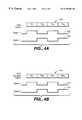
- FIG. 4Ais a timing diagram showing the DAC output and the state of the switch shown in FIG. 3 A.
- FIG. 4Bshows the ADC sample signal and the state of switch 340 shown in FIG. 3 B.
- FIG. 5Ais a block diagram illustrating how two upstream signals are switched to be sampled by a single analog to digital converter in a central office.
- FIG. 5Bshows timing diagrams for the switches shown in FIG. 5 A.
- FIG. 6Ais a block diagram illustrating the transmit path and the receive path for a remote ADSL communication terminal.
- FIG. 6Bshows the time division multiplexed output of a DAC and the state of two switches.
- FIG. 6Cis a block diagram illustrating a multiplexed DAC that is used to process an ADSL signal and a modem signal for a remote unit.
- FIG. 6Dis a block diagram illustrating a multiplexed ADC that is used to process both a received ADSL signal and a modem signal for a remote unit.
- the present inventionis described below in an embodiment that processes ADSL signals such as are specified in ITU Standard G.992.1, which is herein incorporated by reference for all purposes.
- the inventionmay be used with ADSL-lite signals such as are specified in ITU Standard G.992.2, which is herein incorporated by reference for all purposes.
- the inventionis also useful for processing other DSL signals such as HDSL or SDSL.
- the architecture and methodis also useful for processing signals conforming to other modulation schemes such as Home phone network alliance (Home PNA) signals.
- Home PNAHome phone network alliance
- FIG. 3Ais a block diagram illustrating a central office transmission path that includes two independent ADSL lines.
- An ADSL transceiver 300outputs a signal to a DAC 302 .
- DAC 302is configured to receive a signal from the ADSL transceiver that includes time division multiplexed modulation code for two different ADSL lines.
- ADSL transceiver 300may include one or more DMT signal encoders that generate DMT signals. Alternatively, two ADSL transceivers could be used with a combiner that interleaves the two DMT signals into a time division multiplexed signal.
- the time division multiplexed signalmay be generated by a single transmitter or multiple transmitters and combined by a time division multiplexer that receives multiple signals and combines them into a time division multiplexed signal.
- DAC 302outputs an analog signal that is time division multiplexed as is shown in FIG. 4 A.
- the output of DAC 302is sent to a switch 304 .
- Switch 304alternately connects DAC 302 to a first transmitter 306 and a second transmitter 308 .
- the timing diagram for switch 304is also illustrated in FIG. 4A.
- a first selected output of switch 304is connected to a first transmitter 306 and a second selected output of switch 304 is connected to a second transmitter 308 .
- the transmittersare each connected to a separate ADSL line. It should be noted that the transmitters generally include a reconstruction filter that conditions the output of the DAC for transmission over an ADSL line.
- the downstream transmission bandwidthis 1.104 MHz on each line.
- the DACis selected to run at four times the bandwidth which is twice the Nyquist limit of two times the bandwidth.
- the DACruns at 8.832 MHz.
- a single DACis used to produce the analog signals for two ADSL lines.
- a single DACmay be used to generate signals for more than two ADSL lines.
- the 8.832 MHz DACcould be used to generate up to four ADSL lines in a system where the Nyquist limit is used.
- FIG. 3Bis a block diagram illustrating a receive path for an ADSL central office that includes two ADSL lines.
- the signal from a first ADSL line 320is input to a receiver 322 .
- a second ADSL line 330is input into a second receiver 332 .
- the output of receiver 322is at a node 324 .
- the output of receiver 332is at a node 334 .
- a switch 340selects between node 324 and 334 as the input to an analog to digital converter (ADC) 342 .
- ADCanalog to digital converter
- the output of analog to digital converter 342is input to an ADSL transceiver 344 .
- the analog to digital converteris used to digitize the received analog signals from two ADSL lines by alternating the line used as the input to the ADC using switch 340 .
- a timing diagram for switch 340is provided in FIG. 4B along with a plot of the signal digitized by ADC 342 .
- ADC 342 and DAC 302are both included in a single CODEC.
- the data bandwidth in the upstream direction received by the central officeis less than the bandwidth in the downstream direction.
- the standardis 138 kHz bandwidth in the upstream direction and in Europe using ISDN lines, the standard is 276 kHz.
- the ADCis set to sample the signal at least four times the bandwidth of the upstream data.
- an ADCthat samples at 4.416 megasamples per second is used, which is well within this criteria. When such an ADC is used, it would be possible to receive signals from greater than two lines and to use a switch that switches between those lines.
- FIG. 4Ais a timing diagram showing the DAC output and the state of switch 304 from FIG. 3 A.
- DAC output 400includes analog data for transmitter one interleaved with data for transmitter two. The data for the two transmitters is thus time division multiplexed.
- a select signal 402is shown which is high when the switch is connected to the first transmitter.
- the select signalis synchronized with the DAC output so that it is high when data for transmitter one is output from the DAC.
- a select signal 404is shown which is high when switch 304 is connected to the input of transmitter 308 .
- Select signal 404is high when data for transmitter two is output by the DAC.
- FIG. 4Bshows the ADC sample signal and the state of switch 340 in FIG. 3B.
- a select signal 410is high when switch 340 is connected to the output of receiver one.
- select signal 410is high
- the ADC sample sign alcorresponds to the signal from receiver one.
- a select signal 412is high when switch 340 is connected to receiver two.
- the ADC sampled signal 414corresponds to receiver two when select signal 412 is high.
- FIG. 5Ais a block diagram illustrating how two upstream signals are switched to be sampled by a single analog to digital converter in a central office.
- a first switch 502 and a second switch 504are connected to separate voltages generated from separate ADSL lines carrying signals in the upstream direction to the central office.
- FIG. 5Bshows timing diagrams for the switches shown in FIG. 5 A. Switches 502 and 504 are alternatively closed so that the voltage on the corresponding lines are alternatively applied to a sampling capacitor 506 . Sampling capacitor 506 is connected to an amplifier 508 . Switch 502 is closed when signal 550 is high and switch 504 is closed when signal 552 is high.
- the feedback loop for amplifier 508includes a capacitor 510 , a switch 512 and a switch 514 .
- a timing diagram for switches 512 and 514is shown as signal 554 . When signal 554 is high, the switches are closed to close the feedback loop. When signal 554 is low, switch 512 is open and switch 514 is connected to artificial ground.
- the two analog inputsmay be multiplexed and applied to an analog to digital converter so that they may be both digitized by the same analog to digital converter.
- the outputis taken at a node 520 located at the output of the amplifier.
- a single DAC and ADC(which may be implemented as a single CODEC) may be used to transmit signals on two separate ADSL lines and to receive signals from two separate ADSL lines by using time division multiplexing.
- more than two linesmay be used by selecting appropriate sampling rates for the ADC and output frequencies for the DAC.
- a single CODECmay be used for two lines in the central office, saving chip cost as well as requiring less power distribution.
- Similar advantagescan be realized by providing a single CODEC for processing both the transmit and echo cancellation signals in a remote ADSL chip set, although the remote ADSL receiver/transmitter that receives downstream ADSL signals and transmits upstream ADSL signals need not implement multiple lines using a single chip or chip set because a remote unit generally is connected to only one ADSL line. Also, power distribution issues are not as important at a remote station. However, it is possible to reduce chip costs by using a single DAC to output an analog signal for transmission to the central office as well as an analog signal derived from that transmission used to correct error caused by leakage of the transmitted signal into the received signal path through a hybrid.
- the upstream and downstream bandsoverlap, and it is necessary for the ADSL chip at a remote station to generate for the receive signal an echo cancellation signal that is derived from the signal being transmitted for the purpose of canceling out leakage of the transmitted signal into the received signal path.
- the ADSL signals in both the upstream and downstream directionare both transmitted on the same line.
- a hybrid networkis used by the remote unit to isolate the transmitter from the receiver so the signal being transmitted does not interfere with the received signal.
- variance in line characteristicspresents a problem. As a result, some leakage from the transmission line to the receive line does occur.
- This leakageis modeled digitally and an echo cancellation processor inputs the output code and generates an echo cancellation signal designed to cancel out the leakage of the transmitted signal to the received line.
- a second digital to analog converter independent of the digital analog converter used to generate the transmitted signalis used to generate the analog echo cancellation signal that is added to the incoming received signal for the purpose of canceling leakage from the transmitted signal through the hybrid. It would be desirable if the analog echo cancellation signal could be generated by the same digital to analog converter that is used to generate the transmitted signal.
- FIG. 6Ais a block diagram illustrating the transmit path and the receive path for a remote ADSL communication terminal.
- a DMT encoderencodes a digital signal that is input to a DAC 601 .
- the output of DAC 601is connected to both a first switch 602 and a second switch 604 .
- a timing diagram for the output of the DAC and for switches 602 and 604is provided in FIG. 6 B.
- switch 602When switch 602 is closed, the output of DAC 601 is connected to a transmitter 612 that sends the upstream transmission from the DAC to a hybrid 620 that is connected to an ADSL line 622 .
- the transmittersgenerally include a reconstruction filter and a programmable attenuator that conditions the output of the DAC for transmission over an ADSL line. It should be understood that when the DAC is described as connected to the transmitter or the transmitter is described as connected to an ADSL line, that such a description is intended to cover cases where such connections are made either directly or through intermediate filters or devices that condition the signal such as attenuators.
- the output of DAC 601is connected to an echo cancellation filter 614 .
- the output of echo cancellation filter 614is inverted and fed to an adder 624 that also receives incoming downstream transmissions from the central office through hybrid 620 .
- the echo cancellation signalis added to the receive signal and the resulting signal is input to a receiver 630 which is connected to an ADC 632 .
- FIG. 6Bshows the time division multiplexed output of DAC 601 and the state of switch 602 and switch 604 .
- the output 650 of DAC 601alternates between values that correspond to the signal being transmitted and the echo cancellation signal.
- a signal 652represents the state of switch one. When signal 652 is high, the output of the DAC corresponds to the upstream transmitted signal.
- a signal 654corresponds to the state of switch 604 . When signal 654 is high, the output of DAC 601 corresponds to the echo cancellation signal.
- DAC 601is time division multiplexed to provide both the upstream transmission signal as well as an echo cancellation signal used to cancel leakage of the upstream transmission signal into the downstream receive signal path. It should be noted that in one embodiment a DAC is selected that outputs a signal at a frequency of 4.416 MHz. This output rate is more than sufficient to provide an output at a frequency that is more than four times the upstream data rate of 138 kHz (or 276 kHz for ISDN lines in Europe). The inclusion of only one DAC in the remote unit lowers the chip costs of the unit.
- FIG. 6Cis a block diagram illustrating a multiplexed DAC that is used to process an ADSL signal and a modem signal for a remote unit.
- a DMT encoder 660encodes a digital signal that is selectively input by a switch 664 to a DAC 666 .
- a modem encoder 662also encodes a digital signal that is selectively input by switch 664 to DAC 666 .
- the output of DAC 666is selectively connected by a switch 668 to an ADSL filter and transmitter 670 or to a POTS modem filter and transmitter 672 .
- the filters and transmittersmay be separate in some embodiments and that a programmable gain amplifier or programmable attenuator may also be used.
- Switch 664 and switch 668are synchronized so that DMT encoder 660 is connected to the DAC input when the DAC output is connected to ADSL transceiver 670 and modem encoder 662 is connected to DAC input when POTS modem 672 is connected to the DAC output.
- FIG. 6Dis a block diagram illustrating a multiplexed ADC that is used to process both a received ADSL signal and a modem signal for a remote unit.
- An ADSL line and a POTS lineare selectively connected by a switch 684 to an ADC 686 .
- the ADSL line and the POTS lineare generally connected to the ADC through a series of filters and/or programmable gain amplifiers or programmable attenuators.
- ADSL line and the POTS linemay be connected to the ADC directly through switch 684 or indirectly through such other devices.
- the output of ADC 686is selectively output to an ADSL processor 690 and a modem processor 692 .
- Switch 684 and switch 688are synchronized so that ADSL line 680 is connected to the ADC input when the ADC output is connected to ADSL processor 690 and POTS line 682 is connected to the ADC input when modem processor 692 is connected to the ADC output.
- a system and method for using only a single DAC to provide both an upstream transmitted signal and a downstream echo cancellation signal in an ADSL systemhas been disclosed.
- a single DAC and ADCare also provided at a remote unit for processing both ADSL and POTS signals.
- a system and method for using only a single ADC to process input from more than one ADSL line coming into a central officehas been disclosed as well.
Landscapes
- Engineering & Computer Science (AREA)
- Signal Processing (AREA)
- Computer Networks & Wireless Communication (AREA)
- Telephonic Communication Services (AREA)
Abstract
Description
Claims (24)
Priority Applications (3)
| Application Number | Priority Date | Filing Date | Title |
|---|---|---|---|
| US09/250,426US6459684B1 (en) | 1998-10-14 | 1999-02-16 | Multiplexed codec for an ADSL system |
| PCT/US2000/003277WO2000049725A1 (en) | 1999-02-16 | 2000-02-08 | Multiplexed codec for an adsl system |
| AU33587/00AAU3358700A (en) | 1999-02-16 | 2000-02-08 | Multiplexed codec for an adsl system |
Applications Claiming Priority (2)
| Application Number | Priority Date | Filing Date | Title |
|---|---|---|---|
| US10425698P | 1998-10-14 | 1998-10-14 | |
| US09/250,426US6459684B1 (en) | 1998-10-14 | 1999-02-16 | Multiplexed codec for an ADSL system |
Publications (1)
| Publication Number | Publication Date |
|---|---|
| US6459684B1true US6459684B1 (en) | 2002-10-01 |
Family
ID=22947697
Family Applications (1)
| Application Number | Title | Priority Date | Filing Date |
|---|---|---|---|
| US09/250,426Expired - LifetimeUS6459684B1 (en) | 1998-10-14 | 1999-02-16 | Multiplexed codec for an ADSL system |
Country Status (3)
| Country | Link |
|---|---|
| US (1) | US6459684B1 (en) |
| AU (1) | AU3358700A (en) |
| WO (1) | WO2000049725A1 (en) |
Cited By (16)
| Publication number | Priority date | Publication date | Assignee | Title |
|---|---|---|---|---|
| US20010046289A1 (en)* | 2000-04-07 | 2001-11-29 | Robinson Timothy B. | Method and apparatus for transceiver noise reduction in a frame-based communications network |
| US20030108164A1 (en)* | 2001-02-08 | 2003-06-12 | Laurin Jeremy S. | Simultaneous, multiple digital presentation content block, channel independent presentation controller |
| US6674382B1 (en)* | 2002-05-08 | 2004-01-06 | Analog Devices, Inc. | Line driver structures that enhance driver performance |
| US20040120482A1 (en)* | 2002-12-20 | 2004-06-24 | Bentley Ronald Locker | System and method for reducing disruption in a DSL environment caused by a pots transient event |
| US20040160949A1 (en)* | 2003-02-19 | 2004-08-19 | Kim Yong-Ki | Apparatus and method for transmitting voice data on ADSL subscriber Board |
| US6829292B1 (en)* | 2000-01-03 | 2004-12-07 | Symmetricom, Inc. | Increasing gain with isolating upstream and downstream filters and amplifiers |
| US20060023645A1 (en)* | 2002-06-07 | 2006-02-02 | Hench John J | Method and system for providing an analog fron end for multiline transmission in communication systems |
| US20060029207A1 (en)* | 2004-07-12 | 2006-02-09 | Luis Larzabal | Amplifier for unshielded twisted pair wire signals |
| US7031380B1 (en)* | 1999-09-28 | 2006-04-18 | Texas Instruments Incorporated | Multi-client ADSL modem |
| US7031378B1 (en)* | 2000-06-23 | 2006-04-18 | Globespan, Inc. | Unified DSL transceiver |
| US20060098804A1 (en)* | 2004-07-12 | 2006-05-11 | Phylogy, Inc., A Ca Corporation | High performance ADSL line conditioner system and method |
| US20060120443A1 (en)* | 1999-09-28 | 2006-06-08 | Yaqi Cheng | Multi-client ADSL modem |
| US20070140469A1 (en)* | 2004-07-12 | 2007-06-21 | Phylogy, Inc., A California Corporation | Multi-stage differential warping amplifier and method |
| US20090262759A1 (en)* | 2006-06-09 | 2009-10-22 | British Telecommunications Public Limited Company | Communication |
| US20110228708A1 (en)* | 1999-05-27 | 2011-09-22 | Avinoam Rubinstain | Ethernet transport over a telephone line |
| US20240072988A1 (en)* | 2022-08-30 | 2024-02-29 | Aeonsemi, Inc. | Canceller adaptation gating |
Families Citing this family (1)
| Publication number | Priority date | Publication date | Assignee | Title |
|---|---|---|---|---|
| CN106059591A (en)* | 2016-06-18 | 2016-10-26 | 海城市石油化工仪器厂 | Apparatus and method for expanding single-channel high-accuracy digital to analog converter (DAC) into multi-channel high-accuracy DAC |
Citations (10)
| Publication number | Priority date | Publication date | Assignee | Title |
|---|---|---|---|---|
| US5512898A (en)* | 1993-04-30 | 1996-04-30 | At&T Corp. | Data converter with minimum phase FIR filter and method for calculating filter coefficients |
| US5673290A (en)* | 1994-04-14 | 1997-09-30 | Amati Communications Corporation | ADSL compatible discrete multi-tone apparatus |
| US5742527A (en)* | 1996-03-15 | 1998-04-21 | Motorola, Inc. | Flexible asymmetrical digital subscriber line (ADSL) receiver, central office using same, and method therefor |
| US5812786A (en)* | 1995-06-21 | 1998-09-22 | Bell Atlantic Network Services, Inc. | Variable rate and variable mode transmission system |
| US5889856A (en) | 1997-05-22 | 1999-03-30 | Centillium Technology Corp. | ADSL integrated line card with digital splitter and POTS CODEC without bulky analog splitter |
| US5960036A (en)* | 1996-11-04 | 1999-09-28 | Motorola, Inc. | Apparatus and method for auto-configuring a communication system |
| US6005873A (en)* | 1997-08-27 | 1999-12-21 | Eci Telecom Ltd. | Apparatus and method for concurrent voice and data transmission |
| US6005893A (en)* | 1997-09-23 | 1999-12-21 | Telefonaktiebolaget Lm Ericsson | Reduced complexity bit allocation to subchannels in a multi-carrier, high speed data transmission system |
| US6028867A (en)* | 1998-06-15 | 2000-02-22 | Covad Communications Group, Inc. | System, method, and network for providing high speed remote access from any location connected by a local loop to a central office |
| US6028891A (en)* | 1996-06-25 | 2000-02-22 | Analog Devices, Inc. | Asymmetric digital subscriber loop transceiver and method |
- 1999
- 1999-02-16USUS09/250,426patent/US6459684B1/ennot_activeExpired - Lifetime
- 2000
- 2000-02-08WOPCT/US2000/003277patent/WO2000049725A1/enactiveApplication Filing
- 2000-02-08AUAU33587/00Apatent/AU3358700A/ennot_activeAbandoned
Patent Citations (10)
| Publication number | Priority date | Publication date | Assignee | Title |
|---|---|---|---|---|
| US5512898A (en)* | 1993-04-30 | 1996-04-30 | At&T Corp. | Data converter with minimum phase FIR filter and method for calculating filter coefficients |
| US5673290A (en)* | 1994-04-14 | 1997-09-30 | Amati Communications Corporation | ADSL compatible discrete multi-tone apparatus |
| US5812786A (en)* | 1995-06-21 | 1998-09-22 | Bell Atlantic Network Services, Inc. | Variable rate and variable mode transmission system |
| US5742527A (en)* | 1996-03-15 | 1998-04-21 | Motorola, Inc. | Flexible asymmetrical digital subscriber line (ADSL) receiver, central office using same, and method therefor |
| US6028891A (en)* | 1996-06-25 | 2000-02-22 | Analog Devices, Inc. | Asymmetric digital subscriber loop transceiver and method |
| US5960036A (en)* | 1996-11-04 | 1999-09-28 | Motorola, Inc. | Apparatus and method for auto-configuring a communication system |
| US5889856A (en) | 1997-05-22 | 1999-03-30 | Centillium Technology Corp. | ADSL integrated line card with digital splitter and POTS CODEC without bulky analog splitter |
| US6005873A (en)* | 1997-08-27 | 1999-12-21 | Eci Telecom Ltd. | Apparatus and method for concurrent voice and data transmission |
| US6005893A (en)* | 1997-09-23 | 1999-12-21 | Telefonaktiebolaget Lm Ericsson | Reduced complexity bit allocation to subchannels in a multi-carrier, high speed data transmission system |
| US6028867A (en)* | 1998-06-15 | 2000-02-22 | Covad Communications Group, Inc. | System, method, and network for providing high speed remote access from any location connected by a local loop to a central office |
Non-Patent Citations (1)
| Title |
|---|
| Conroy, Cormac, et al., "A CMOS Analog Front-End IC for DMT ADSL", 1999 IEEE International Solid-StateCircuits Conference, 0-7803-5129-0/99. |
Cited By (30)
| Publication number | Priority date | Publication date | Assignee | Title |
|---|---|---|---|---|
| US9088435B2 (en)* | 1999-05-27 | 2015-07-21 | Lantiq Beteiligungs-GmbH & Co.KG | Ethernet transport over a telephone line |
| US20110228708A1 (en)* | 1999-05-27 | 2011-09-22 | Avinoam Rubinstain | Ethernet transport over a telephone line |
| US7031380B1 (en)* | 1999-09-28 | 2006-04-18 | Texas Instruments Incorporated | Multi-client ADSL modem |
| US20060120443A1 (en)* | 1999-09-28 | 2006-06-08 | Yaqi Cheng | Multi-client ADSL modem |
| US6829292B1 (en)* | 2000-01-03 | 2004-12-07 | Symmetricom, Inc. | Increasing gain with isolating upstream and downstream filters and amplifiers |
| US7254116B2 (en)* | 2000-04-07 | 2007-08-07 | Broadcom Corporation | Method and apparatus for transceiver noise reduction in a frame-based communications network |
| US20020041570A1 (en)* | 2000-04-07 | 2002-04-11 | Ptasinski Henry S. | Method for providing dynamic adjustment of frame encoding parameters in a frame-based communications network |
| US20010046289A1 (en)* | 2000-04-07 | 2001-11-29 | Robinson Timothy B. | Method and apparatus for transceiver noise reduction in a frame-based communications network |
| US20020057717A1 (en)* | 2000-04-07 | 2002-05-16 | Mallory Tracy D. | Method of sharing information among a plurality of stations in a frame-based communications networK |
| US7822005B2 (en) | 2000-04-07 | 2010-10-26 | Broadcom Corporation | Method for providing dynamic adjustment of frame encoding parameters in a frame-based communications network |
| US20090046593A1 (en)* | 2000-04-07 | 2009-02-19 | Ptasinski Henry S | Method for providing dynamic adjustment of frame encoding parameters in a frame-based communications network |
| US7406106B2 (en) | 2000-04-07 | 2008-07-29 | Broadcom Corporation | Method of sharing information among a plurality of stations in a frame-based communications network |
| US7388853B2 (en) | 2000-04-07 | 2008-06-17 | Broadcom Corporation | Method for providing dynamic adjustment of frame encoding parameters in a frame-based communications network |
| US7031378B1 (en)* | 2000-06-23 | 2006-04-18 | Globespan, Inc. | Unified DSL transceiver |
| US20030108164A1 (en)* | 2001-02-08 | 2003-06-12 | Laurin Jeremy S. | Simultaneous, multiple digital presentation content block, channel independent presentation controller |
| US6674382B1 (en)* | 2002-05-08 | 2004-01-06 | Analog Devices, Inc. | Line driver structures that enhance driver performance |
| US20060023645A1 (en)* | 2002-06-07 | 2006-02-02 | Hench John J | Method and system for providing an analog fron end for multiline transmission in communication systems |
| US7796544B2 (en)* | 2002-06-07 | 2010-09-14 | Tokyo Electron Limited | Method and system for providing an analog front end for multiline transmission in communication systems |
| US20040120482A1 (en)* | 2002-12-20 | 2004-06-24 | Bentley Ronald Locker | System and method for reducing disruption in a DSL environment caused by a pots transient event |
| US20040160949A1 (en)* | 2003-02-19 | 2004-08-19 | Kim Yong-Ki | Apparatus and method for transmitting voice data on ADSL subscriber Board |
| US8160237B2 (en) | 2004-07-12 | 2012-04-17 | Actelis Networks, Inc. | Multi-stage differential warping amplifier and method |
| US7587042B2 (en) | 2004-07-12 | 2009-09-08 | Phylogy, Inc. | High performance ADSL line conditioner system and method |
| WO2006017236A3 (en)* | 2004-07-12 | 2006-04-27 | Phylogy Inc | Amplifier for unshielded twisted pair wire signals |
| US20060029207A1 (en)* | 2004-07-12 | 2006-02-09 | Luis Larzabal | Amplifier for unshielded twisted pair wire signals |
| US20060098804A1 (en)* | 2004-07-12 | 2006-05-11 | Phylogy, Inc., A Ca Corporation | High performance ADSL line conditioner system and method |
| US20070140469A1 (en)* | 2004-07-12 | 2007-06-21 | Phylogy, Inc., A California Corporation | Multi-stage differential warping amplifier and method |
| US7110528B2 (en) | 2004-07-12 | 2006-09-19 | Phylogy, Inc. | Amplifier for unshielded twisted pair wire signals |
| US20090262759A1 (en)* | 2006-06-09 | 2009-10-22 | British Telecommunications Public Limited Company | Communication |
| US8730987B2 (en) | 2006-06-09 | 2014-05-20 | British Telecommunications Public Limited Company | Framing of analog communication |
| US20240072988A1 (en)* | 2022-08-30 | 2024-02-29 | Aeonsemi, Inc. | Canceller adaptation gating |
Also Published As
| Publication number | Publication date |
|---|---|
| WO2000049725A1 (en) | 2000-08-24 |
| WO2000049725A9 (en) | 2001-09-20 |
| AU3358700A (en) | 2000-09-04 |
Similar Documents
| Publication | Publication Date | Title |
|---|---|---|
| US6459684B1 (en) | Multiplexed codec for an ADSL system | |
| US7031394B2 (en) | Communication systems conveying voice and data signals over standard telephone lines | |
| US6466088B1 (en) | Method and apparatus for multi-channel X-DSL line driver | |
| US6324212B1 (en) | Apparatus using low spectrum selectively for providing both ADSL and POTS service | |
| CA2301546C (en) | Apparatus and method for concurrent voice and data transmission | |
| US6144695A (en) | Method and apparatus for reducing near-end crosstalk (NEXT) in discrete multi-tone modulator/demodulators | |
| US6067316A (en) | Circuit for combined xDSL and other services | |
| EP1069700B1 (en) | Echo cancellation for an ADSL modem | |
| EP0795984A2 (en) | Flexible asymmetrical digital subscriber line (ADSL) receiver, central office using same, and method therefor | |
| JP3634727B2 (en) | Remote terminal and method of transmitting data from remote terminal | |
| EP0740451B1 (en) | Method, interface modules and telephone network for multiplexing and demultiplexing an analog MTS (message telephone service) signal and an ADSL (asymmetric digital subscriber line) datastream | |
| US20110019725A1 (en) | Dsl method having variable upload/download bit rate and application-specific dynamic profile switching | |
| US6404774B1 (en) | Method using low spectrum selectively for providing both ADSL and POTS service | |
| AU707189B2 (en) | Method of bi-directional data transmission via a two-wire line | |
| US20020034220A1 (en) | Apparatus and method for digital subscriber line signal communications | |
| KR100468078B1 (en) | Line terminating device for a subscriber line | |
| US7020101B2 (en) | Method of implementing a repeater, and a transceiver unit | |
| EP2425538B1 (en) | Method and apparatus for optimizing dynamic range in dmt modems | |
| US6262972B1 (en) | Digital multitone communication trunk | |
| US6741604B1 (en) | ADSL transmission in the presence of low-frequency network services | |
| US6965637B2 (en) | System and method for controlling line driver power in a shared digital subscriber line modem | |
| US20030012352A1 (en) | Application of metering tones to a DSL and voice communications network | |
| EP0990341B1 (en) | Vdsl modem divided into a digital and an analog part | |
| US20020027900A1 (en) | System and method for programmable spectrum management | |
| JP3758035B2 (en) | Data transmission equipment |
Legal Events
| Date | Code | Title | Description |
|---|---|---|---|
| AS | Assignment | Owner name:CISCO TECHNOLOGY, INC, CALIFORNIA Free format text:ASSIGNMENT OF ASSIGNORS INTEREST;ASSIGNORS:CONROY, CORMAC S.;SHENG, SAMUEL W.;UEHARA, GREGORY T.;REEL/FRAME:009943/0874;SIGNING DATES FROM 19990408 TO 19990426 | |
| AS | Assignment | Owner name:DATAPATH SYSTEMS, INC., CALIFORNIA Free format text:ASSIGNMENT OF ASSIGNORS INTEREST;ASSIGNORS:CONROY, CORMAC S.;SHENG, SAMUEL W.;UEHARA, GREGORY T.;REEL/FRAME:010807/0315;SIGNING DATES FROM 19990408 TO 19990426 | |
| AS | Assignment | Owner name:LSI LOGIC CORPORATION, CALIFORNIA Free format text:ASSIGNMENT OF ASSIGNORS INTEREST;ASSIGNOR:DATA PATH SYSTEMS, INC.;REEL/FRAME:011198/0844 Effective date:20001003 | |
| STCF | Information on status: patent grant | Free format text:PATENTED CASE | |
| FPAY | Fee payment | Year of fee payment:4 | |
| FEPP | Fee payment procedure | Free format text:PAYOR NUMBER ASSIGNED (ORIGINAL EVENT CODE: ASPN); ENTITY STATUS OF PATENT OWNER: LARGE ENTITY | |
| FPAY | Fee payment | Year of fee payment:8 | |
| FPAY | Fee payment | Year of fee payment:12 | |
| AS | Assignment | Owner name:DEUTSCHE BANK AG NEW YORK BRANCH, AS COLLATERAL AG Free format text:PATENT SECURITY AGREEMENT;ASSIGNORS:LSI CORPORATION;AGERE SYSTEMS LLC;REEL/FRAME:032856/0031 Effective date:20140506 | |
| AS | Assignment | Owner name:LSI CORPORATION, CALIFORNIA Free format text:CHANGE OF NAME;ASSIGNOR:LSI LOGIC CORPORATION;REEL/FRAME:033102/0270 Effective date:20070406 | |
| AS | Assignment | Owner name:AVAGO TECHNOLOGIES GENERAL IP (SINGAPORE) PTE. LTD Free format text:ASSIGNMENT OF ASSIGNORS INTEREST;ASSIGNOR:LSI CORPORATION;REEL/FRAME:035390/0388 Effective date:20140814 | |
| AS | Assignment | Owner name:LSI CORPORATION, CALIFORNIA Free format text:TERMINATION AND RELEASE OF SECURITY INTEREST IN PATENT RIGHTS (RELEASES RF 032856-0031);ASSIGNOR:DEUTSCHE BANK AG NEW YORK BRANCH, AS COLLATERAL AGENT;REEL/FRAME:037684/0039 Effective date:20160201 Owner name:AGERE SYSTEMS LLC, PENNSYLVANIA Free format text:TERMINATION AND RELEASE OF SECURITY INTEREST IN PATENT RIGHTS (RELEASES RF 032856-0031);ASSIGNOR:DEUTSCHE BANK AG NEW YORK BRANCH, AS COLLATERAL AGENT;REEL/FRAME:037684/0039 Effective date:20160201 | |
| AS | Assignment | Owner name:BANK OF AMERICA, N.A., AS COLLATERAL AGENT, NORTH CAROLINA Free format text:PATENT SECURITY AGREEMENT;ASSIGNOR:AVAGO TECHNOLOGIES GENERAL IP (SINGAPORE) PTE. LTD.;REEL/FRAME:037808/0001 Effective date:20160201 Owner name:BANK OF AMERICA, N.A., AS COLLATERAL AGENT, NORTH Free format text:PATENT SECURITY AGREEMENT;ASSIGNOR:AVAGO TECHNOLOGIES GENERAL IP (SINGAPORE) PTE. LTD.;REEL/FRAME:037808/0001 Effective date:20160201 | |
| AS | Assignment | Owner name:AVAGO TECHNOLOGIES GENERAL IP (SINGAPORE) PTE. LTD., SINGAPORE Free format text:TERMINATION AND RELEASE OF SECURITY INTEREST IN PATENTS;ASSIGNOR:BANK OF AMERICA, N.A., AS COLLATERAL AGENT;REEL/FRAME:041710/0001 Effective date:20170119 Owner name:AVAGO TECHNOLOGIES GENERAL IP (SINGAPORE) PTE. LTD Free format text:TERMINATION AND RELEASE OF SECURITY INTEREST IN PATENTS;ASSIGNOR:BANK OF AMERICA, N.A., AS COLLATERAL AGENT;REEL/FRAME:041710/0001 Effective date:20170119 | |
| AS | Assignment | Owner name:AVAGO TECHNOLOGIES INTERNATIONAL SALES PTE. LIMITE Free format text:MERGER;ASSIGNOR:AVAGO TECHNOLOGIES GENERAL IP (SINGAPORE) PTE. LTD.;REEL/FRAME:047195/0026 Effective date:20180509 | |
| AS | Assignment | Owner name:AVAGO TECHNOLOGIES INTERNATIONAL SALES PTE. LIMITE Free format text:CORRECTIVE ASSIGNMENT TO CORRECT THE EFFECTIVE DATE OF MERGER PREVIOUSLY RECORDED ON REEL 047195 FRAME 0026. ASSIGNOR(S) HEREBY CONFIRMS THE MERGER;ASSIGNOR:AVAGO TECHNOLOGIES GENERAL IP (SINGAPORE) PTE. LTD.;REEL/FRAME:047477/0423 Effective date:20180905 |