US6459266B1 - Sonde locator - Google Patents
Sonde locatorDownload PDFInfo
- Publication number
- US6459266B1 US6459266B1US09/491,797US49179700AUS6459266B1US 6459266 B1US6459266 B1US 6459266B1US 49179700 AUS49179700 AUS 49179700AUS 6459266 B1US6459266 B1US 6459266B1
- Authority
- US
- United States
- Prior art keywords
- locator
- magnetic field
- compass
- boring tool
- solenoid
- Prior art date
- Legal status (The legal status is an assumption and is not a legal conclusion. Google has not performed a legal analysis and makes no representation as to the accuracy of the status listed.)
- Expired - Lifetime
Links
Images


Classifications
- E—FIXED CONSTRUCTIONS
- E21—EARTH OR ROCK DRILLING; MINING
- E21B—EARTH OR ROCK DRILLING; OBTAINING OIL, GAS, WATER, SOLUBLE OR MELTABLE MATERIALS OR A SLURRY OF MINERALS FROM WELLS
- E21B47/00—Survey of boreholes or wells
- E21B47/02—Determining slope or direction
- E21B47/024—Determining slope or direction of devices in the borehole
- E—FIXED CONSTRUCTIONS
- E21—EARTH OR ROCK DRILLING; MINING
- E21B—EARTH OR ROCK DRILLING; OBTAINING OIL, GAS, WATER, SOLUBLE OR MELTABLE MATERIALS OR A SLURRY OF MINERALS FROM WELLS
- E21B47/00—Survey of boreholes or wells
- E21B47/02—Determining slope or direction
- E21B47/022—Determining slope or direction of the borehole, e.g. using geomagnetism
- E21B47/0228—Determining slope or direction of the borehole, e.g. using geomagnetism using electromagnetic energy or detectors therefor
- E21B47/0232—Determining slope or direction of the borehole, e.g. using geomagnetism using electromagnetic energy or detectors therefor at least one of the energy sources or one of the detectors being located on or above the ground surface
- G—PHYSICS
- G01—MEASURING; TESTING
- G01V—GEOPHYSICS; GRAVITATIONAL MEASUREMENTS; DETECTING MASSES OR OBJECTS; TAGS
- G01V3/00—Electric or magnetic prospecting or detecting; Measuring magnetic field characteristics of the earth, e.g. declination, deviation
- G01V3/08—Electric or magnetic prospecting or detecting; Measuring magnetic field characteristics of the earth, e.g. declination, deviation operating with magnetic or electric fields produced or modified by objects or geological structures or by detecting devices
- G01V3/081—Electric or magnetic prospecting or detecting; Measuring magnetic field characteristics of the earth, e.g. declination, deviation operating with magnetic or electric fields produced or modified by objects or geological structures or by detecting devices the magnetic field is produced by the objects or geological structures
Definitions
- the present inventionrelates to a locator for determining the position of a sonde.
- a sondemay, for example, be mounted on a boring tool and may generate electromagnetic signals which enable the position of that boring tool to be determined by the locator.
- WO 96/29615corresponding to U.S. Pat. No. 5,917,325, the disclosure of which is incorporated herein by reference, we discussed an arrangement for locating an underground boring tool in which a magnetic field generated by a solenoid was detected at two measuring locations. Use may be made of the relationship between the axial and radial fields of the solenoids, and a tilt sensor was included to indicate if the axis of the solenoid was not horizontal. The solenoid and tilt sensor may then be incorporated in a sonde.
- the locatoruses an aerial array to measure field components in three mutually perpendicular directions. Using amplitude and phase data from each aerial array, the location of the sonde, and hence the boring tool, can be determined.
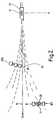
- an underground boring tool 10has a sonde 11 which contains a solenoid which generates a magnetic field, with the axis 12 of the solenoid being aligned with the longitudinal axis of the boring tool 10 .
- the axis 12will be the direction of movement of the boring tool, unless the boring tool is diverted by ground variation or obstacles, or by deliberate steering action.
- a locator having an aerial array comprising three coils X 3 Y 3 and Z 3will, when placed directly above the sonde 11 and in alignment with it so that the Y 3 coil is parallel to the axis 12 , the Z 3 coil is perpendicular to the axis in a way which makes that coil Z 3 vertical when the axis 12 is horizontal, have a maximum signal in the direction axis 12 with the X 3 and Y 3 coils detecting a null field. Any diversions from this position will result in signals from the X 3 and Z 3 coils, which signals will vary in amplitude and phase according to the extent and direction of such divergence.
- a similar arrangementwill apply if the locator is positioned ahead of the sonde 11 although the signal magnitude will then be reduced due to distance. In tracking a boring tool, it is common to position a locator ahead of the tool in the anticipated direction of its motion.
- a locatoris provided with a detector for detecting the magnetic field generated by, for example, a solenoid in an inaccessible object which might be an item such as an underground boring tool.
- the detectorpreferably comprises an aerial array of three mutually perpendicular coils for detecting the generated magnetic field.
- FIG. 1shows fields generated by a solenoid-containing sonde, and has already been discussed
- FIG. 2shows location of a boring tool using a locator according to the present invention.
- an underground boring tool 10has a sonde with a solenoid generating a magnetic field, the axis of the solenoid being shown at 12 .
- This arrangementis similar to that shown in FIG. 1 and corresponding components will be indicated by the same reference numerals.
- the operatorseeks to place the locator 20 directly ahead of the boring tool 10 at a position B.
- the coilsare as in FIG. 1, and will not be described in more detail now.
- a locator 20 aIf a locator 20 a is mis-aligned with the axis 12 , and moved toward the axis to a position B 1 , measurements is taken by the locator 20 a may be incorrect.
- the locator 20has thereon a magnetic compass 21 .
- the compasspoints NS, and so defines the orientation of the locator 20 relative to the Earth's magnetic field. Therefore, when the locator 20 is moved from one position to another, e.g. from a position over the boring tool 1 to the position B 2 in FIG. 2, the locator can ensure that the compass orientation remains unchanged, so that the locator 20 has the same orientation relative to the Earth's magnetic field. Thus, mis-alignments such as shown at position B 1 in FIG. 2 can be avoided. Hence, incorrect measurements may be avoided.
- the compass 21is unaffected by the magnetic field from the sonde 2 , which field is shown schematically by dotted lines, because such a field is an A.C. field.
- the magnetic compass 21may be a simple compass of conventional type, such as those used by walkers, since all that is needed is for the operator of the locator to have a visual indication of the direction to the boring tool.
- the need to record a compass bearing at the initial positioncan be obviated if the compass is provided with an adjustable pointer or marked bezel, which can be set to match the north point of the needle, in a similar manner to the setting of a barometer pointer to its last reading.
Landscapes
- Physics & Mathematics (AREA)
- Engineering & Computer Science (AREA)
- Life Sciences & Earth Sciences (AREA)
- Geology (AREA)
- Mining & Mineral Resources (AREA)
- Geophysics (AREA)
- Environmental & Geological Engineering (AREA)
- General Life Sciences & Earth Sciences (AREA)
- Remote Sensing (AREA)
- Electromagnetism (AREA)
- Fluid Mechanics (AREA)
- Geochemistry & Mineralogy (AREA)
- General Physics & Mathematics (AREA)
- Geophysics And Detection Of Objects (AREA)
Abstract
Description
1. Field of the Invention
The present invention relates to a locator for determining the position of a sonde. Such a sonde may, for example, be mounted on a boring tool and may generate electromagnetic signals which enable the position of that boring tool to be determined by the locator.
2. Description of Related Art
In WO 96/29615 corresponding to U.S. Pat. No. 5,917,325, the disclosure of which is incorporated herein by reference, we discussed an arrangement for locating an underground boring tool in which a magnetic field generated by a solenoid was detected at two measuring locations. Use may be made of the relationship between the axial and radial fields of the solenoids, and a tilt sensor was included to indicate if the axis of the solenoid was not horizontal. The solenoid and tilt sensor may then be incorporated in a sonde. In general, the locator uses an aerial array to measure field components in three mutually perpendicular directions. Using amplitude and phase data from each aerial array, the location of the sonde, and hence the boring tool, can be determined.
Thus, as shown in FIG. 1, anunderground boring tool 10 has asonde 11 which contains a solenoid which generates a magnetic field, with theaxis 12 of the solenoid being aligned with the longitudinal axis of theboring tool 10. Theaxis 12 will be the direction of movement of the boring tool, unless the boring tool is diverted by ground variation or obstacles, or by deliberate steering action. A locator having an aerial array comprising three coils X3Y3and Z3will, when placed directly above thesonde 11 and in alignment with it so that the Y3coil is parallel to theaxis 12, the Z3coil is perpendicular to the axis in a way which makes that coil Z3vertical when theaxis 12 is horizontal, have a maximum signal in thedirection axis 12 with the X3and Y3coils detecting a null field. Any diversions from this position will result in signals from the X3and Z3coils, which signals will vary in amplitude and phase according to the extent and direction of such divergence. A similar arrangement will apply if the locator is positioned ahead of thesonde 11 although the signal magnitude will then be reduced due to distance. In tracking a boring tool, it is common to position a locator ahead of the tool in the anticipated direction of its motion.
However, if the locator is not correctly aligned, an incorrect measurement will result. Whilst the operator may endeavour to maintain the orientation of the locator relative to theboring tool 10, this is not always reliable since the boring tool cannot be seen.
A locator is provided with a detector for detecting the magnetic field generated by, for example, a solenoid in an inaccessible object which might be an item such as an underground boring tool. The detector preferably comprises an aerial array of three mutually perpendicular coils for detecting the generated magnetic field. When the locator is moved from a first position to a second position errors may arise in the measurement due to misalignment of the locator. In order to minimize such errors, a magnetic compass is provided on the locator to insure that the locator can be maintained in the same position relative to the earth's magnetic field. The magnetic compass is not affected by the magnetic field generated by the solenoid as this magnetic field is an A.C. magnetic field.
An embodiment of the present invention will now be described in detail, by way of example, with reference to the accompanying drawings, in which:
FIG. 1 shows fields generated by a solenoid-containing sonde, and has already been discussed; and
FIG. 2 shows location of a boring tool using a locator according to the present invention.
Referring to FIG. 2, anunderground boring tool 10 has a sonde with a solenoid generating a magnetic field, the axis of the solenoid being shown at12. This arrangement is similar to that shown in FIG.1 and corresponding components will be indicated by the same reference numerals. In order to achieve satisfactory location of theboring tool 10 using alocator 20, the operator seeks to place thelocator 20 directly ahead of theboring tool 10 at a position B. In order to do this, it is usual for the operator first to place thelocator 20 slightly to one side of the expected line of theaxis 12, at position B2 in FIG.2 and then move thelocator 20 until it coincides with theaxis 12, on the basis of amplitude and phase measurements from the coils of thelocator 20. The coils are as in FIG. 1, and will not be described in more detail now.
If alocator 20ais mis-aligned with theaxis 12, and moved toward the axis to a position B1, measurements is taken by thelocator 20amay be incorrect.
Therefore, in accordance with the present invention, thelocator 20 has thereon amagnetic compass 21. The compass points NS, and so defines the orientation of thelocator 20 relative to the Earth's magnetic field. Therefore, when thelocator 20 is moved from one position to another, e.g. from a position over the boring tool1 to the position B2 in FIG. 2, the locator can ensure that the compass orientation remains unchanged, so that thelocator 20 has the same orientation relative to the Earth's magnetic field. Thus, mis-alignments such as shown at position B1 in FIG. 2 can be avoided. Hence, incorrect measurements may be avoided. Note that thecompass 21 is unaffected by the magnetic field from the sonde2, which field is shown schematically by dotted lines, because such a field is an A.C. field.
At its simplest, themagnetic compass 21 may be a simple compass of conventional type, such as those used by walkers, since all that is needed is for the operator of the locator to have a visual indication of the direction to the boring tool. However, it is also possible to use other compass arrangements. In particular, the need to record a compass bearing at the initial position can be obviated if the compass is provided with an adjustable pointer or marked bezel, which can be set to match the north point of the needle, in a similar manner to the setting of a barometer pointer to its last reading. By turning the locator until the needle and adjustable mark correspond, the operator then knows that the locator has its original orientation.
Other arrangements such as magnetometer or ‘solid-state’ compasses or gyroscopic devices might find application in some circumstances.
Claims (5)
1. A method for detecting the relationship between a locator and an inaccessible object, said inaccessible object having means for generating a magnetic field and said locator having detecting means for detecting the generated magnetic field and a magnetic compass, the method comprising:
(a) measuring horizontal and vertical components of said generated magnetic field using the locator in a first position;
(b) processing said measurements to determine the separation of said inaccessible object from said locator in the first position;
(c) moving said locator to a second position and using said compass to ensure that said locator has the same orientation relative to the Earth's magnetic field as in said first position;
(d) measuring horizontal and vertical components of said generated magnetic field using the locator in the second position; and,
(e) processing said measurements to determine the separation of said inaccessible object from said locator at the second position.
2. A method according toclaim 1 wherein said generated magnetic field is an A.C. magnetic field.
3. A method according toclaim 1 wherein said magnetic compass has a display which is visible from the outside of said locator.
4. A method according theclaim 1 , wherein said means for generating a magnetic field is a solenoid.
5. A method according toclaim 1 , wherein the inaccessible object is a boring tool.
Applications Claiming Priority (2)
| Application Number | Priority Date | Filing Date | Title |
|---|---|---|---|
| GB9901708 | 1999-01-26 | ||
| GBGB9901708.9AGB9901708D0 (en) | 1999-01-26 | 1999-01-26 | Sonde locator |
Publications (1)
| Publication Number | Publication Date |
|---|---|
| US6459266B1true US6459266B1 (en) | 2002-10-01 |
Family
ID=10846536
Family Applications (1)
| Application Number | Title | Priority Date | Filing Date |
|---|---|---|---|
| US09/491,797Expired - LifetimeUS6459266B1 (en) | 1999-01-26 | 2000-01-26 | Sonde locator |
Country Status (3)
| Country | Link |
|---|---|
| US (1) | US6459266B1 (en) |
| DE (1) | DE10003253A1 (en) |
| GB (2) | GB9901708D0 (en) |
Cited By (20)
| Publication number | Priority date | Publication date | Assignee | Title |
|---|---|---|---|---|
| US6717410B2 (en)* | 2000-09-08 | 2004-04-06 | Merlin Technology, Inc. | Bore location system |
| US20070247162A1 (en)* | 1996-04-18 | 2007-10-25 | Mercer John E | Tracking the Positional Relationship Between a Boring Tool and One or More Buried Lines using a Composite Magnetic Signal |
| US7640105B2 (en) | 2007-03-13 | 2009-12-29 | Certus View Technologies, LLC | Marking system and method with location and/or time tracking |
| USD634656S1 (en) | 2010-03-01 | 2011-03-22 | Certusview Technologies, Llc | Shaft of a marking device |
| USD634657S1 (en) | 2010-03-01 | 2011-03-22 | Certusview Technologies, Llc | Paint holder of a marking device |
| USD634655S1 (en) | 2010-03-01 | 2011-03-22 | Certusview Technologies, Llc | Handle of a marking device |
| USD643321S1 (en) | 2010-03-01 | 2011-08-16 | Certusview Technologies, Llc | Marking device |
| US8060304B2 (en) | 2007-04-04 | 2011-11-15 | Certusview Technologies, Llc | Marking system and method |
| US8280631B2 (en) | 2008-10-02 | 2012-10-02 | Certusview Technologies, Llc | Methods and apparatus for generating an electronic record of a marking operation based on marking device actuations |
| US8311765B2 (en) | 2009-08-11 | 2012-11-13 | Certusview Technologies, Llc | Locating equipment communicatively coupled to or equipped with a mobile/portable device |
| US8400155B2 (en) | 2008-10-02 | 2013-03-19 | Certusview Technologies, Llc | Methods and apparatus for displaying an electronic rendering of a locate operation based on an electronic record of locate information |
| US8442766B2 (en) | 2008-10-02 | 2013-05-14 | Certusview Technologies, Llc | Marking apparatus having enhanced features for underground facility marking operations, and associated methods and systems |
| USD684067S1 (en) | 2012-02-15 | 2013-06-11 | Certusview Technologies, Llc | Modular marking device |
| US8473209B2 (en) | 2007-03-13 | 2013-06-25 | Certusview Technologies, Llc | Marking apparatus and marking methods using marking dispenser with machine-readable ID mechanism |
| US8478523B2 (en) | 2007-03-13 | 2013-07-02 | Certusview Technologies, Llc | Marking apparatus and methods for creating an electronic record of marking apparatus operations |
| US8620616B2 (en) | 2009-08-20 | 2013-12-31 | Certusview Technologies, Llc | Methods and apparatus for assessing marking operations based on acceleration information |
| US8620572B2 (en) | 2009-08-20 | 2013-12-31 | Certusview Technologies, Llc | Marking device with transmitter for triangulating location during locate operations |
| US8626571B2 (en) | 2009-02-11 | 2014-01-07 | Certusview Technologies, Llc | Management system, and associated methods and apparatus, for dispatching tickets, receiving field information, and performing a quality assessment for underground facility locate and/or marking operations |
| US8965700B2 (en) | 2008-10-02 | 2015-02-24 | Certusview Technologies, Llc | Methods and apparatus for generating an electronic record of environmental landmarks based on marking device actuations |
| US9097522B2 (en) | 2009-08-20 | 2015-08-04 | Certusview Technologies, Llc | Methods and marking devices with mechanisms for indicating and/or detecting marking material color |
Families Citing this family (2)
| Publication number | Priority date | Publication date | Assignee | Title |
|---|---|---|---|---|
| GB0319483D0 (en)* | 2003-08-19 | 2003-09-17 | Marsh Hugh R | Position locator |
| GB2412737A (en)* | 2004-03-31 | 2005-10-05 | Radiodetection Ltd | Enhanced sonde recognition |
Citations (9)
| Publication number | Priority date | Publication date | Assignee | Title |
|---|---|---|---|---|
| US4323848A (en)* | 1980-03-17 | 1982-04-06 | Cornell Research Foundation, Inc. | Plural sensor magnetometer arrangement for extended lateral range electrical conductivity logging |
| US4438401A (en) | 1979-07-31 | 1984-03-20 | Kokusai Denshin Denwa Co., Ltd. | System for detecting a cable buried under the seabed |
| US4710708A (en)* | 1981-04-27 | 1987-12-01 | Develco | Method and apparatus employing received independent magnetic field components of a transmitted alternating magnetic field for determining location |
| WO1988004436A1 (en) | 1986-12-10 | 1988-06-16 | Lehmer Douglas P | Means and method of locating covered artifacts |
| US4825165A (en)* | 1978-02-08 | 1989-04-25 | Helms Ronald L | Method and apparatus for detecting a transient phenomenon by monitoring variations of an alternating component of a vertical current emanating from the earth's surface |
| WO1990000259A1 (en) | 1988-06-28 | 1990-01-11 | Radiodetection Limited | System for detecting the location and orientation of an object |
| US5122750A (en)* | 1989-03-15 | 1992-06-16 | Schonstedt Instrument Company | Methods employing permanent magnets for marking, locating, tracing and identifying hidden objects such as buried fiber optic cables |
| US5321361A (en)* | 1992-10-05 | 1994-06-14 | Goodman William L | Apparatus and method for detecting magnetically detectable plastic pipe and other sources of magnetic fields from a distance using a vertically aligned gradiometer on a horizontal support |
| US5917325A (en)* | 1995-03-21 | 1999-06-29 | Radiodetection Limited | Method for locating an inaccessible object having a magnetic field generating solenoid |
- 1999
- 1999-01-26GBGBGB9901708.9Apatent/GB9901708D0/ennot_activeCeased
- 2000
- 2000-01-24GBGB0001575Apatent/GB2347218B/ennot_activeExpired - Fee Related
- 2000-01-26USUS09/491,797patent/US6459266B1/ennot_activeExpired - Lifetime
- 2000-01-26DEDE10003253Apatent/DE10003253A1/ennot_activeWithdrawn
Patent Citations (9)
| Publication number | Priority date | Publication date | Assignee | Title |
|---|---|---|---|---|
| US4825165A (en)* | 1978-02-08 | 1989-04-25 | Helms Ronald L | Method and apparatus for detecting a transient phenomenon by monitoring variations of an alternating component of a vertical current emanating from the earth's surface |
| US4438401A (en) | 1979-07-31 | 1984-03-20 | Kokusai Denshin Denwa Co., Ltd. | System for detecting a cable buried under the seabed |
| US4323848A (en)* | 1980-03-17 | 1982-04-06 | Cornell Research Foundation, Inc. | Plural sensor magnetometer arrangement for extended lateral range electrical conductivity logging |
| US4710708A (en)* | 1981-04-27 | 1987-12-01 | Develco | Method and apparatus employing received independent magnetic field components of a transmitted alternating magnetic field for determining location |
| WO1988004436A1 (en) | 1986-12-10 | 1988-06-16 | Lehmer Douglas P | Means and method of locating covered artifacts |
| WO1990000259A1 (en) | 1988-06-28 | 1990-01-11 | Radiodetection Limited | System for detecting the location and orientation of an object |
| US5122750A (en)* | 1989-03-15 | 1992-06-16 | Schonstedt Instrument Company | Methods employing permanent magnets for marking, locating, tracing and identifying hidden objects such as buried fiber optic cables |
| US5321361A (en)* | 1992-10-05 | 1994-06-14 | Goodman William L | Apparatus and method for detecting magnetically detectable plastic pipe and other sources of magnetic fields from a distance using a vertically aligned gradiometer on a horizontal support |
| US5917325A (en)* | 1995-03-21 | 1999-06-29 | Radiodetection Limited | Method for locating an inaccessible object having a magnetic field generating solenoid |
Cited By (51)
| Publication number | Priority date | Publication date | Assignee | Title |
|---|---|---|---|---|
| US20070247162A1 (en)* | 1996-04-18 | 2007-10-25 | Mercer John E | Tracking the Positional Relationship Between a Boring Tool and One or More Buried Lines using a Composite Magnetic Signal |
| US7403014B2 (en)* | 1996-04-18 | 2008-07-22 | Merlin Technology, Inc. | Tracking the positional relationship between a boring tool and one or more buried lines using a composite magnetic signal |
| US8188746B2 (en) | 1996-05-03 | 2012-05-29 | Merlin Technology, Inc. | Tracking the positional relationship between a boring tool and at least one buried lines |
| US8786285B2 (en) | 1996-05-03 | 2014-07-22 | Merlin Technology Inc. | Apparatus for monitoring a positional relationship between a boring tool and an inground line |
| US20110101985A1 (en)* | 1996-05-03 | 2011-05-05 | Mercer John E | Tracking the positional relationship between a boring tool and one or more buried lines using a composite magnetic signal |
| US7888939B2 (en) | 1996-05-03 | 2011-02-15 | Merlin Technology, Inc. | Tracking the positional relationship between a boring tool and one or more buried lines using a composite magnetic signal |
| US7786732B2 (en) | 1996-05-03 | 2010-08-31 | Merlin Technology Inc. | Apparatus for monitoring a positional relationship between a boring tool and an inground line |
| US7151376B2 (en) | 2000-09-08 | 2006-12-19 | Merlin Technology, Inc. | Bore location system |
| US20050242818A1 (en)* | 2000-09-08 | 2005-11-03 | Morio Mizuno | Bore location system |
| US6717410B2 (en)* | 2000-09-08 | 2004-04-06 | Merlin Technology, Inc. | Bore location system |
| US7078905B2 (en) | 2000-09-08 | 2006-07-18 | Merlin Technology, Inc. | Bore location system |
| US20060132136A1 (en)* | 2000-09-08 | 2006-06-22 | Morio Mizuno | Bore location system |
| US20040164740A1 (en)* | 2000-09-08 | 2004-08-26 | Morio Mizuno | Bore location system |
| US6922056B2 (en) | 2000-09-08 | 2005-07-26 | Merlin Technology, Inc. | Bore location system |
| US8775077B2 (en) | 2007-03-13 | 2014-07-08 | Certusview Technologies, Llc | Systems and methods for using location data to electronically display dispensing of markers by a marking system or marking tool |
| US9086277B2 (en) | 2007-03-13 | 2015-07-21 | Certusview Technologies, Llc | Electronically controlled marking apparatus and methods |
| US8700325B2 (en) | 2007-03-13 | 2014-04-15 | Certusview Technologies, Llc | Marking apparatus and methods for creating an electronic record of marking operations |
| US8407001B2 (en) | 2007-03-13 | 2013-03-26 | Certusview Technologies, Llc | Systems and methods for using location data to electronically display dispensing of markers by a marking system or marking tool |
| US7640105B2 (en) | 2007-03-13 | 2009-12-29 | Certus View Technologies, LLC | Marking system and method with location and/or time tracking |
| US8478523B2 (en) | 2007-03-13 | 2013-07-02 | Certusview Technologies, Llc | Marking apparatus and methods for creating an electronic record of marking apparatus operations |
| US8473209B2 (en) | 2007-03-13 | 2013-06-25 | Certusview Technologies, Llc | Marking apparatus and marking methods using marking dispenser with machine-readable ID mechanism |
| US8903643B2 (en) | 2007-03-13 | 2014-12-02 | Certusview Technologies, Llc | Hand-held marking apparatus with location tracking system and methods for logging geographic location of same |
| US8401791B2 (en) | 2007-03-13 | 2013-03-19 | Certusview Technologies, Llc | Methods for evaluating operation of marking apparatus |
| US8060304B2 (en) | 2007-04-04 | 2011-11-15 | Certusview Technologies, Llc | Marking system and method |
| US8374789B2 (en) | 2007-04-04 | 2013-02-12 | Certusview Technologies, Llc | Systems and methods for using marking information to electronically display dispensing of markers by a marking system or marking tool |
| US8386178B2 (en) | 2007-04-04 | 2013-02-26 | Certusview Technologies, Llc | Marking system and method |
| US8467969B2 (en) | 2008-10-02 | 2013-06-18 | Certusview Technologies, Llc | Marking apparatus having operational sensors for underground facility marking operations, and associated methods and systems |
| US8612148B2 (en) | 2008-10-02 | 2013-12-17 | Certusview Technologies, Llc | Marking apparatus configured to detect out-of-tolerance conditions in connection with underground facility marking operations, and associated methods and systems |
| US8457893B2 (en) | 2008-10-02 | 2013-06-04 | Certusview Technologies, Llc | Methods and apparatus for generating an electronic record of a marking operation including service-related information and/or ticket information |
| US8400155B2 (en) | 2008-10-02 | 2013-03-19 | Certusview Technologies, Llc | Methods and apparatus for displaying an electronic rendering of a locate operation based on an electronic record of locate information |
| US8770140B2 (en) | 2008-10-02 | 2014-07-08 | Certusview Technologies, Llc | Marking apparatus having environmental sensors and operations sensors for underground facility marking operations, and associated methods and systems |
| US8361543B2 (en) | 2008-10-02 | 2013-01-29 | Certusview Technologies, Llc | Methods and apparatus for displaying an electronic rendering of a marking operation based on an electronic record of marking information |
| US8478525B2 (en) | 2008-10-02 | 2013-07-02 | Certusview Technologies, Llc | Methods, apparatus, and systems for analyzing use of a marking device by a technician to perform an underground facility marking operation |
| US9542863B2 (en) | 2008-10-02 | 2017-01-10 | Certusview Technologies, Llc | Methods and apparatus for generating output data streams relating to underground utility marking operations |
| US8478524B2 (en) | 2008-10-02 | 2013-07-02 | Certusview Technologies, Llc | Methods and apparatus for dispensing marking material in connection with underground facility marking operations based on environmental information and/or operational information |
| US8442766B2 (en) | 2008-10-02 | 2013-05-14 | Certusview Technologies, Llc | Marking apparatus having enhanced features for underground facility marking operations, and associated methods and systems |
| US8280631B2 (en) | 2008-10-02 | 2012-10-02 | Certusview Technologies, Llc | Methods and apparatus for generating an electronic record of a marking operation based on marking device actuations |
| US8965700B2 (en) | 2008-10-02 | 2015-02-24 | Certusview Technologies, Llc | Methods and apparatus for generating an electronic record of environmental landmarks based on marking device actuations |
| US8731830B2 (en) | 2008-10-02 | 2014-05-20 | Certusview Technologies, Llc | Marking apparatus for receiving environmental information regarding underground facility marking operations, and associated methods and systems |
| US9185176B2 (en) | 2009-02-11 | 2015-11-10 | Certusview Technologies, Llc | Methods and apparatus for managing locate and/or marking operations |
| US8731999B2 (en) | 2009-02-11 | 2014-05-20 | Certusview Technologies, Llc | Management system, and associated methods and apparatus, for providing improved visibility, quality control and audit capability for underground facility locate and/or marking operations |
| US8626571B2 (en) | 2009-02-11 | 2014-01-07 | Certusview Technologies, Llc | Management system, and associated methods and apparatus, for dispatching tickets, receiving field information, and performing a quality assessment for underground facility locate and/or marking operations |
| US8311765B2 (en) | 2009-08-11 | 2012-11-13 | Certusview Technologies, Llc | Locating equipment communicatively coupled to or equipped with a mobile/portable device |
| US8620616B2 (en) | 2009-08-20 | 2013-12-31 | Certusview Technologies, Llc | Methods and apparatus for assessing marking operations based on acceleration information |
| US8620572B2 (en) | 2009-08-20 | 2013-12-31 | Certusview Technologies, Llc | Marking device with transmitter for triangulating location during locate operations |
| US9097522B2 (en) | 2009-08-20 | 2015-08-04 | Certusview Technologies, Llc | Methods and marking devices with mechanisms for indicating and/or detecting marking material color |
| USD643321S1 (en) | 2010-03-01 | 2011-08-16 | Certusview Technologies, Llc | Marking device |
| USD634655S1 (en) | 2010-03-01 | 2011-03-22 | Certusview Technologies, Llc | Handle of a marking device |
| USD634657S1 (en) | 2010-03-01 | 2011-03-22 | Certusview Technologies, Llc | Paint holder of a marking device |
| USD634656S1 (en) | 2010-03-01 | 2011-03-22 | Certusview Technologies, Llc | Shaft of a marking device |
| USD684067S1 (en) | 2012-02-15 | 2013-06-11 | Certusview Technologies, Llc | Modular marking device |
Also Published As
| Publication number | Publication date |
|---|---|
| GB2347218B (en) | 2001-01-17 |
| GB2347218A (en) | 2000-08-30 |
| GB0001575D0 (en) | 2000-03-15 |
| GB9901708D0 (en) | 1999-03-17 |
| DE10003253A1 (en) | 2000-08-17 |
Similar Documents
| Publication | Publication Date | Title |
|---|---|---|
| US6459266B1 (en) | Sonde locator | |
| US5917325A (en) | Method for locating an inaccessible object having a magnetic field generating solenoid | |
| CA2187487C (en) | Rotating magnet for distance and direction measurements | |
| CN100395563C (en) | Buried line locator with integral position sensing | |
| US6731108B2 (en) | Device with a magnetic position encoder | |
| US4072200A (en) | Surveying of subterranean magnetic bodies from an adjacent off-vertical borehole | |
| CA1295126C (en) | Roll-independent magnetometer system | |
| US8769838B2 (en) | Surveyor 's rod and magnetic locator | |
| US20070057840A1 (en) | Methods and systems using relative sensing to locate targets | |
| US10976441B2 (en) | Method of using GNSS system having magnetic locator | |
| CN101010563A (en) | Combination laser system and global navigation satellite system | |
| CN102272556A (en) | alignment system | |
| US4250626A (en) | Electronic compass | |
| US12007491B2 (en) | GPS assisted walkover locating system and method | |
| US11619759B2 (en) | Dipole locator using balanced antenna signals | |
| US4637480A (en) | Azimuth measuring method for non-vertical drilling | |
| US20080129599A1 (en) | Systems and methods for locating targets using digital elevation model survey points | |
| US7386942B2 (en) | Method and apparatus for mapping the trajectory in the subsurface of a borehole | |
| CN108710145A (en) | A kind of unmanned plane positioning system and method | |
| US12117315B2 (en) | Magnetic position sensor system | |
| JP2866078B2 (en) | Excavation propulsion position detecting device and position detecting method | |
| US11333498B2 (en) | Magnetic compass compensation | |
| RU2365877C1 (en) | Method for definition of magnet deviation on movable object | |
| Mercer | Walk-over locating technology | |
| US2888752A (en) | Navigation system |
Legal Events
| Date | Code | Title | Description |
|---|---|---|---|
| AS | Assignment | Owner name:RADIODETECTION LIMITED, ENGLAND Free format text:ASSIGNMENT OF ASSIGNORS INTEREST;ASSIGNOR:FLING, RICHARD WILLIAM;REEL/FRAME:010569/0384 Effective date:20000125 | |
| STCF | Information on status: patent grant | Free format text:PATENTED CASE | |
| FPAY | Fee payment | Year of fee payment:4 | |
| FPAY | Fee payment | Year of fee payment:8 | |
| FPAY | Fee payment | Year of fee payment:12 | |
| SULP | Surcharge for late payment | Year of fee payment:11 |