US6459094B1 - Method for stitching partial radiation images to reconstruct a full image - Google Patents
Method for stitching partial radiation images to reconstruct a full imageDownload PDFInfo
- Publication number
- US6459094B1 US6459094B1US09/782,724US78272401AUS6459094B1US 6459094 B1US6459094 B1US 6459094B1US 78272401 AUS78272401 AUS 78272401AUS 6459094 B1US6459094 B1US 6459094B1
- Authority
- US
- United States
- Prior art keywords
- image
- images
- screen
- end edge
- edge
- Prior art date
- Legal status (The legal status is an assumption and is not a legal conclusion. Google has not performed a legal analysis and makes no representation as to the accuracy of the status listed.)
- Expired - Lifetime, expires
Links
- 238000000034methodMethods0.000titleclaimsabstractdescription40
- 230000005855radiationEffects0.000title1
- OAICVXFJPJFONN-UHFFFAOYSA-NPhosphorusChemical compound[P]OAICVXFJPJFONN-UHFFFAOYSA-N0.000claimsabstractdescription41
- 238000006073displacement reactionMethods0.000claimsabstractdescription35
- 239000002131composite materialSubstances0.000claimsabstractdescription14
- 230000007704transitionEffects0.000claimsdescription11
- 238000012937correctionMethods0.000claimsdescription9
- 238000001514detection methodMethods0.000claimsdescription3
- 239000011159matrix materialSubstances0.000claims1
- 230000008569processEffects0.000description17
- 238000005314correlation functionMethods0.000description9
- 238000012545processingMethods0.000description9
- 230000006870functionEffects0.000description5
- 230000008901benefitEffects0.000description4
- 238000002601radiographyMethods0.000description4
- 230000000875corresponding effectEffects0.000description3
- 230000000694effectsEffects0.000description3
- 230000000630rising effectEffects0.000description3
- 238000013519translationMethods0.000description3
- 238000013459approachMethods0.000description2
- 230000007423decreaseEffects0.000description2
- 238000013461designMethods0.000description2
- 238000001125extrusionMethods0.000description2
- 238000003384imaging methodMethods0.000description2
- 238000012886linear functionMethods0.000description2
- 230000000737periodic effectEffects0.000description2
- 230000000712assemblyEffects0.000description1
- 238000000429assemblyMethods0.000description1
- 230000015572biosynthetic processEffects0.000description1
- 210000000988bone and boneAnatomy0.000description1
- 230000002596correlated effectEffects0.000description1
- 230000001419dependent effectEffects0.000description1
- 238000010586diagramMethods0.000description1
- 238000001914filtrationMethods0.000description1
- 238000013178mathematical modelMethods0.000description1
- 238000012986modificationMethods0.000description1
- 230000004048modificationEffects0.000description1
- 206010039722scoliosisDiseases0.000description1
- 210000001519tissueAnatomy0.000description1
Images


Classifications
- G—PHYSICS
- G03—PHOTOGRAPHY; CINEMATOGRAPHY; ANALOGOUS TECHNIQUES USING WAVES OTHER THAN OPTICAL WAVES; ELECTROGRAPHY; HOLOGRAPHY
- G03B—APPARATUS OR ARRANGEMENTS FOR TAKING PHOTOGRAPHS OR FOR PROJECTING OR VIEWING THEM; APPARATUS OR ARRANGEMENTS EMPLOYING ANALOGOUS TECHNIQUES USING WAVES OTHER THAN OPTICAL WAVES; ACCESSORIES THEREFOR
- G03B42/00—Obtaining records using waves other than optical waves; Visualisation of such records by using optical means
- G03B42/02—Obtaining records using waves other than optical waves; Visualisation of such records by using optical means using X-rays
- G03B42/04—Holders for X-ray films
- G—PHYSICS
- G01—MEASURING; TESTING
- G01T—MEASUREMENT OF NUCLEAR OR X-RADIATION
- G01T1/00—Measuring X-radiation, gamma radiation, corpuscular radiation, or cosmic radiation
- G01T1/16—Measuring radiation intensity
- G01T1/20—Measuring radiation intensity with scintillation detectors
- G01T1/2012—Measuring radiation intensity with scintillation detectors using stimulable phosphors, e.g. stimulable phosphor sheets
- G01T1/2014—Reading out of stimulable sheets, e.g. latent image
Definitions
- This inventionrelates in general to digital radiography, and in particular to the imaging of a long human body part, such as the spine or legs, using a storage phosphor-based computed radiography system.
- the cassette holderis bulky and does not conform to ISO/ANSI standards, which means that it can not be placed in the bucky grid holder that is designed for the current screen-film systems.
- U.S. patent application Ser. No.: 09/742,509 filed Dec. 20, 2000discloses a method that is based on an extended length cassette with two 35 ⁇ 43 cm phosphor screens built inside. The two phosphor screens are slightly overlapped in the center of the cassette (FIGS. 1 - 3 ). The overall cassette size is about 35 ⁇ 85 cm, which nearly doubles the current largest cassette size and allows a fairly long segment of the human body to be imaged at a single exposure. The information recorded in either phosphor screen bears part of the desired final image.
- one end of the cassetteis placed in the CR reader and the first phosphor screen is scanned and stored, the cassette is then removed from the reader and inverted to allow the second phosphor screen to be read in the same manner as the first.
- the two imagescan then be processed into a composite full image if so desired.
- the length of the cassettecan be designed to be shorter or longer in order to follow the ISO/ANSI standard, such as 36′′ and 51′′ inch long.
- the maximum cassette lengthis approximately twice the maximum allowable scan length of the CR reader.
- Special digital image processingis required to construct a composite full image from the front and back images that are obtained from the two individual phosphor screens.
- the two phosphor screensare packed and partially overlapped inside the single cassette and are therefore not coplanar. This causes the image of the body part to be magnified differently for different locations in the cassette, and a demagnification operation is required as part of the process of registering the front and back images.
- the two phosphor screenswill not be perfectly aligned inside the cassette, and there are translation and rotational displacements introduced by the CR reader during the image readout process. As a result, the placement of the pixels from the front and back images will not be perfectly aligned, and the images will require rotation and translation compensation.
- the aforementioned image registration processingcan be accomplished by de-warping the front and back images to a set of reference markers (with known position) that are imaged in conjunction with the body part.
- reference markerswith known position
- the inventionhas the following advantages.
- FIG. 2is a perspective view showing one storage phosphor screen pulled from one end of the cassette as it would be during processing in CR reader.
- the other end of the cassetteis capable of opening in a like manner.
- FIG. 3is a diagrammatic view showing two phosphor screens which partially overlap in the center of the cassette.
- the deflectorsguide the screens as they approach the center of the cassette to force the overlap.
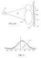
- FIGS. 4A, 4 B and 4 Care diagrammatic views respectively showing how the extended length cassette is used to acquire images, how an object of rectangular shape placed in the patient location is deformed by magnification due to distance variation from the x-ray source to the storage phosphor screen, and how the acquired front and back image look.
- the CR readerover-scans both phosphor screens in the vertical direction of the cassette in order to make the screen ending edges fully visible in both images.
- FIG. 5is a flow diagram showing the image processing steps for automatic formation of a full composite image from first and second images.
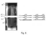
- FIG. 6shows the major image processing steps that are used to automatically find the locations and orientations of the screen ending edges in both the front and the back images, and for finding the location and orientation of the shadow of the front screen ending edge in the back image.
- FIG. 7shows the major image processing steps that are used for finding the horizontal displacement between the front and back images by image-correlation.
- FIG. 8is a graphical illustration of the correlation function.
- FIG. 9shows the composite, stitched full image.
- the present inventionrelates to the radiographic imaging of an elongate object such as the full spine (for diagnosing scoliosis, for example) or leg of a human subject.
- Two contiguous CR plates contained in an elongated cassetteare exposed to a radiographic image of an elongate object to produce a latent image stored in the CR plates.
- the CR platesare removably mounted in the cassette and are sequentially fed to a CR reader where the latent radiographic images are converted to two electronic images which are combined to form an elongated image.
- the elongate imagecan be displayed on an electronic display or printed out on hard copy media.
- storage phosphor cassette 10includes an elongate rectangular shell 12 having first and second open ends 14 and 16 .
- a first storage phosphor plate assembly 18is detachably mounted in shell 12 from the first open end 14 .
- a second storage phosphor plate assembly 20is detachably mounted on shell 12 from the second open end 16 .
- Each assembly 18 , 20includes a respective storage phosphor plate 22 , 24 and a support and latching assembly 26 , 28 .
- Plates 22 , 24are butt joined or overlapped in the central region 29 of shell 12 .
- Shell 12includes upper and lower members 30 , 32 and side extrusions 34 , 36 which together form a rectangular shell.
- FIG. 2shows first storage phosphor assembly 18 partially detached from cassette 10 at a reading device (not shown).
- FIG. 3shows a cross-section of cassette 10 showing upper and lower members 30 , 32 having respective opposed inner surfaces 40 , 42 including deflectors 44 , 46 extending therefrom for guiding the inner ends of assemblies 18 , 20 to overlap.
- the first and second images read from first and second storage phosphor plates 22 and 24are formed into a composite image according to the method of the present invention as follows.
- the generation of a full composite image from the front and back imagesis comprised of the following steps: (1) demagnification of each image pixel based on the distance between the x-ray source and the physical location of the pixel in the individual phosphor screen, (2) determination of the rotational displacement and the vertical displacement between the front and back images by matching the front screen ending edge in the front image to it's shadow in the back image, (3) image orientation correction based on the rotational displacement, (4) determination of the horizontal displacement between the front and back images by correlating the image information in the overlapping screen regions, and (5) stitching the front and the back images together along the front screen ending edge based on the horizontal and vertical displacements.
- the patient 403is positioned in the path of the x-ray beam 402 from the x-ray tube 401 .
- the extended length cassette 405is placed behind the patient in order to record the image of the patient.
- the extended length cassette 405can be used with an anti-scatter grid 404 , which is positioned behind the patient 403 but directly in front of the cassette.
- the gridcan be either a stationary type or moving bucky.
- the back screen 407can still record the image of the patient 403 in the screen overlap region 427 .
- the signal-to-noise ratio of the image captured on the back screen in the overlap region 427will be relatively low because of the x-ray attenuation caused by the front screen.
- the image content recorded by the two screens in the overlap regionis the same.
- This redundant informationis then used to register the front and back images to produce a full patient image.
- the front screen ending edge 408can impose a distinctive edge shadow on the back screen. By comparing the location and orientation of the front screen ending edge with its shadow in the back image, the relative orientation and vertical displacement between the two images is determined.
- the exposure process described in this paragraphcorresponds to element 500 in FIG. 5 .
- the extended length CR cassetteis sent to the CR reader for image readout.
- the front phosphor screen 410is scanned using a laser beam in a line-by-line format as described by element 412 .
- the depicted signal from the phosphor screenwhich is linearly proportional to the magnitude of the recorded patient image signal, is extracted and converted into digital format.
- the CR readermay stop the reading process when the laser scan line nearly reaches the screen ending edge 414 . This does not guarantee that the complete information of the ending edge will be recorded in the acquired image, which is required by this invention for image registration. To address this issue, the CR reader must over-scan the phosphor screen, i.e., scan slightly beyond the end of the screen. In FIG.
- element 420represents the image acquired from the front screen, and shows that the screen ending edge, 422 , is captured completely inside the image.
- the front imagetherefore is partitioned into two regions by the screen ending edge: the normal image area and the over-scanned image area.
- the cassetteis removed from the reader and inverted to allow the back screen 407 ( 411 ) to be read in the same manner as the front screen.
- the laser beamconducts the scan in a format as indicated by element 413 . Therefore, to restore the correct orientation of the back image, the acquired image must be flipped once horizontally and once vertically after being stored in the CR memory.
- Element 421shows the acquired back image after the flip operations. Since both the back and front screens are of the same size, the back screen will also be over-scanned beyond its ending edge 415 (FIG. 4 B). Consequently, the screen ending edge 423 will be captured completely inside the acquired back image 421 . Due to screen overlap, the front screen ending edge 414 is also recorded by the back screen, which is indicated by element 425 . The back image is therefore partitioned into three regions by the shadow of the front screen ending edge and further by the back screen ending edge.
- the end-to-end readout and storage process described in this paragraphcorresponds to element 502 , 504 , 503 , 505 , and 506 as shown in FIG. 5 .
- the front and back storage phosphor screensare not exactly co-planar inside the extended cassette, there is a location dependent, although slight, geometric distortion (magnification) that is introduced, as indicated by elements 416 and 417 .
- the mismatch between the front and back images in the overlap regioncan be as large as 0.5 mm in the image horizontal axis. This can significantly impact the stitching precision and introduce discontinuity adjacent to the seam line in the stitched image. It is therefore necessary to perform distortion correction, especially as the distortion conspicuity increases as the SID decreases.
- the distortion correction processis accomplished using a mathematical model that is based on the geometric placement of the phosphor screens inside the cassette.
- each pixel in the front imageis dewarped using the following equations:
- x and yare image pixel coordinates in the vertical and horizontal axes, respectively, and x′ and y′ are the new image pixel coordinates, respectively
- x maxis the pixel coordinate maximum in the vertical axis
- y cis the center coordinate in the horizontal axis of the image.
- the origin of the image pixel coordinateis defined at the image upper-left comer, with the downward-pointing vertical axis being the positive x-axis and the right-pointing horizontal axis being the y-axis.
- Eq. 1essentially conducts variable correction for each image row but ignores the very small distortion in the vertical direction. The correction is conducted symmetric to the middle column of the image, which is valid because during the x-ray exposure the central x-ray beam is normally centered with the cassette.
- the back imagecan be corrected using the formula given by:
- y ′( y ⁇ y c ) ⁇ g b ⁇ ( x max ⁇ x )/ x max +y c , (2)
- This image demagnification processis indicated by elements 507 and 508 in FIG. 5 . This processing step can be ignored when the SID becomes large (>>180 cm), as the distortion introduced by the magnification factor is negligible.
- FIG. 6describes the preferred embodiment of the detection process.
- a narrow band 602is extracted from the end of the front image 600 .
- the orientation of the screen ending edge 601can have a variation of several degrees in the acquired image from one scan to the next scan. Therefore, the size of the narrow band must be large enough such that the entire screen ending edge is reliably extracted. For an image that has a width of 2,048 pixels, the size of the narrow band should be approximately 200 ⁇ 2,048 pixels.
- the one-dimensional derivative of the imagewhich is computed in the vertical direction using an operator [ ⁇ 1, 0, 1].
- a one-dimensional derivative operatoris preferred because the pixel value discontinuity only occurs across the edge direction, which is always nearly horizontal, and because of the computational efficiency advantages.
- a predefined thresholdis used to select only those candidate edge transition pixels which are of greater magnitude and of falling slope. Element 603 shows the results from this step.
- the screen ending edge locationis successfully found in the front image, it is compared with its shadow in the back image for image registration.
- a similar approach to element 509is used. This is possible because the pixel values in the back image also undergo a strong signal intensity decrement in the screen overlap region 427 (FIG. 4C) due to the high attenuation of the incident x-rays by the front screen during the x-ray exposure.
- the location of the narrow bandneeds to be defined in the back image.
- k and aare the fitting parameters with k the orientation and a the offset.
- parameters k f and kshould be equal because they both represent the orientation of the front screen ending edge. However, they may differ by as much as several degrees in practice for several reasons such as misalignment between the two phosphor screens in the cassette or screen positioning variations in the CR reader during the readout process.
- the deviation between k f and krepresents the orientation misalignment between the front and back images. To assure a seamless composite image after stitching, and to preserve high geometric fidelity, this misalignment must be corrected.
- the first and the second methodshave the advantage of reduced computation because only one of the two images must be rotated.
- FIG. 5element 513 shows the effect of rotating the back image.
- Element 512which shows the effect of rotating the front image, is optional depending on whether method 2 or method 3 was used Since the parameters that are used for aligning the front and back images, e.g., k a , k b , k, a a , a b , and a, are calculated before image rotation, the parameters must be transformed accordingly to reflect the new values in the rotated image(s). The parameters are modified by placing Eqs. 3, 4, and 6 into the transform given by:
- the vertical displacement between the front and back image, x_offsetis defined as the vertical distance from each pixel in the back image to origin of the front image and is given by:
- the location of the screen overlap region 427 (FIG. 4C) in the back imagecan be defined.
- the screen overlap region in the back imageis located between the back screen ending edge and the shadow of the front screen ending edge.
- the size of the regionis calculated based on the equation given by:
- Element 515shows the aforementioned process. Using the computed value of overlap_size, the corresponding region in the front image is derived. This is the region of the same size but with a vertical displacement from the image origin defined by:
- overlap_offset fx max ⁇ ( k a ⁇ y c +a a ) ⁇ overlap_size. (11)
- the image content recorded in the overlap regionsare the same except for some horizontal displacement, y_offset, between the corresponding pixels.
- a one-dimensional correlation functionis computed to find the displacement using the formula given by
- F(x i , y j ) and B(x i , y j )is the pixel value at (x i , y j ) in the extracted overlap region from the front and back images, respectively, and ⁇ is the horizontal displacement parameter for correlation.
- the ⁇ value at which c( ⁇ ) reaches a maximumis the optimal value for y_offset.
- FIG. 7describes the preferred implementation of this operation.
- the overlap region 702 and 703are extracted from the front and back images respectively.
- element 704is obtained by extracting a portion of 702 , then is correlated with 703 to create the correlation function c( ⁇ ), 706 . Similar results can be achieved by correlating a portion of 703 with 702 .
- the maximum of function c( ⁇ )is searched and the corresponding value of ⁇ is identified as y_offset, 707 . Because the edge information in 702 and 703 , including skin line, tissue boundaries, bone edges, collimation boundaries, and hardware labels etc, contribute the most useful information to the correlation, the low frequency content is removed from 702 and 703 in order to improve the correlation robustness.
- the correlation functionis smooth, as indicated by element 810 (FIG. 8 ).
- element 810Normally the correlation function is smooth, as indicated by element 810 (FIG. 8 ).
- element 811FIG. 8 .
- the stationary gridimposes a periodic line pattern artifact in the acquired images, the artifact is particularly dominant when the grid is orientated in the vertical direction, and can correlate with itself, causing small spikes to be introduced on top of the back ground correlation function. This artifact will negatively impact the accuracy of the determination of the location of the true function maximum.
- low-pass filtering of the correlation functionis used before searching for the maximum.
- the process described in this paragraphis represented by element 531 (FIG. 5 ).
- the back imageis stitched to the front image.
- Each pixel of the front imageis copied to the stitched image buffer except those pixels that are beyond the screen ending edge line.
- Each pixel in the back imageis copied to the stitched image buffer with an displacement defined by x_offset and y_offset except those pixels before the shadow of the front screen ending edge.
- the resultant imageis shown in FIG. 9 .
- the process conducted in this paragraphis represented by element 532 (FIG. 5 ).
- 516extract screen overlap region from front image
- 517extract screen overlap region from back image
Landscapes
- Physics & Mathematics (AREA)
- General Physics & Mathematics (AREA)
- Health & Medical Sciences (AREA)
- Life Sciences & Earth Sciences (AREA)
- High Energy & Nuclear Physics (AREA)
- Molecular Biology (AREA)
- Spectroscopy & Molecular Physics (AREA)
- Apparatus For Radiation Diagnosis (AREA)
- Image Processing (AREA)
- Image Analysis (AREA)
- Editing Of Facsimile Originals (AREA)
Abstract
Description
Claims (8)
Priority Applications (3)
| Application Number | Priority Date | Filing Date | Title |
|---|---|---|---|
| US09/782,724US6459094B1 (en) | 2000-12-20 | 2001-02-13 | Method for stitching partial radiation images to reconstruct a full image |
| EP02075399AEP1231484B1 (en) | 2001-02-13 | 2002-02-01 | Method for combining partial radiation images to reconstruct a full image |
| JP2002032905AJP2002301055A (en) | 2001-02-13 | 2002-02-08 | Method for stitching partial radiation image for reconstituting whole image |
Applications Claiming Priority (2)
| Application Number | Priority Date | Filing Date | Title |
|---|---|---|---|
| US09/742,509US6852987B2 (en) | 2000-12-08 | 2000-12-20 | Elongated computed radiography cassette |
| US09/782,724US6459094B1 (en) | 2000-12-20 | 2001-02-13 | Method for stitching partial radiation images to reconstruct a full image |
Related Parent Applications (1)
| Application Number | Title | Priority Date | Filing Date |
|---|---|---|---|
| US09/742,509ContinuationUS6852987B2 (en) | 2000-12-08 | 2000-12-20 | Elongated computed radiography cassette |
Publications (2)
| Publication Number | Publication Date |
|---|---|
| US20020109113A1 US20020109113A1 (en) | 2002-08-15 |
| US6459094B1true US6459094B1 (en) | 2002-10-01 |
Family
ID=25126976
Family Applications (1)
| Application Number | Title | Priority Date | Filing Date |
|---|---|---|---|
| US09/782,724Expired - LifetimeUS6459094B1 (en) | 2000-12-20 | 2001-02-13 | Method for stitching partial radiation images to reconstruct a full image |
Country Status (3)
| Country | Link |
|---|---|
| US (1) | US6459094B1 (en) |
| EP (1) | EP1231484B1 (en) |
| JP (1) | JP2002301055A (en) |
Cited By (29)
| Publication number | Priority date | Publication date | Assignee | Title |
|---|---|---|---|---|
| US20030016787A1 (en)* | 2001-07-20 | 2003-01-23 | Heinz Horbaschek | Method and apparatus for producing an overall image from a number of partial images |
| US20030048938A1 (en)* | 2001-09-11 | 2003-03-13 | Xiaohui Wang | Method for stitching partial radiation images to reconstruct a full image |
| US20030138137A1 (en)* | 2002-01-22 | 2003-07-24 | Ivan Bojer | Radiographic image composition and use |
| US20040071269A1 (en)* | 2002-10-10 | 2004-04-15 | Eastman Kodak Company | Method for automatic arrangement determination of partial radiation images for reconstructing a stitched full image |
| US20040114717A1 (en)* | 2002-07-29 | 2004-06-17 | Kabushiki Kaisha Toshiba | Apparatus and method for processing X-ray images |
| US20040143153A1 (en)* | 2003-01-17 | 2004-07-22 | Sharrow James S. | Devices and methods for manipulation of organ tissue |
| US20040165054A1 (en)* | 2003-02-25 | 2004-08-26 | Saquib Suhail S. | Image stitching for a multi-head printer |
| US20050212839A1 (en)* | 2004-03-23 | 2005-09-29 | Puri Anish N | Print job data processing for multi-head printers |
| US20060064000A1 (en)* | 2004-09-21 | 2006-03-23 | Vizard Douglas L | Apparatus and method for multi-modal imaging |
| US20060262902A1 (en)* | 2005-05-19 | 2006-11-23 | The Regents Of The University Of California | Security X-ray screening system |
| US20060290769A1 (en)* | 2005-06-23 | 2006-12-28 | Polaroid Corporation | Print head pulsing techniques for multicolor printers |
| US20070025642A1 (en)* | 2005-08-01 | 2007-02-01 | Bioptigen, Inc. | Methods, systems and computer program products for analyzing three dimensional data sets obtained from a sample |
| US20070165141A1 (en)* | 2005-11-22 | 2007-07-19 | Yogesh Srinivas | Method and system to manage digital medical images |
| US20080069470A1 (en)* | 2006-09-19 | 2008-03-20 | Songyang Yu | System and method for shutter detection |
| US20080238967A1 (en)* | 2001-05-30 | 2008-10-02 | Zink Imaging, Llc | Print head pulsing techniques for multicolor printers |
| US20090114860A1 (en)* | 2005-09-08 | 2009-05-07 | Gilbert Feke | Apparatus and method for imaging ionizing radiation |
| US20090159805A1 (en)* | 2005-09-08 | 2009-06-25 | Gilbert Feke | Apparatus and method for multi-modal imaging |
| US20090281383A1 (en)* | 2005-09-08 | 2009-11-12 | Rao Papineni | Apparatus and method for external fluorescence imaging of internal regions of interest in a small animal using an endoscope for internal illumination |
| US20090324048A1 (en)* | 2005-09-08 | 2009-12-31 | Leevy Warren M | Method and apparatus for multi-modal imaging |
| US20100022866A1 (en)* | 2005-09-08 | 2010-01-28 | Gilbert Feke | Torsional support apparatus and method for craniocaudal rotation of animals |
| US20100087316A1 (en)* | 2001-05-30 | 2010-04-08 | Day John C | Thermally-Insulating Layers and Direct Thermal Imaging Members Containing Same |
| US20100220836A1 (en)* | 2005-09-08 | 2010-09-02 | Feke Gilbert D | Apparatus and method for multi-modal imaging |
| US20110075798A1 (en)* | 2009-09-30 | 2011-03-31 | Jan Boese | Method for correcting truncated projection data |
| US20110216956A1 (en)* | 2010-03-05 | 2011-09-08 | Bower Bradley A | Methods, Systems and Computer Program Products for Collapsing Volume Data to Lower Dimensional Representations Thereof |
| US20110228900A1 (en)* | 2007-08-13 | 2011-09-22 | Takihito Sakai | Radiographic apparatus |
| WO2011156948A1 (en)* | 2010-06-13 | 2011-12-22 | Nanjing University | Reconstruction of overlapped objects in image |
| US20140264078A1 (en)* | 2013-03-12 | 2014-09-18 | Agfa Healthcare Nv | Radiation Image Read-Out and Cropping System |
| US10048057B2 (en) | 2013-12-05 | 2018-08-14 | Bioptigen, Inc. | Image registration, averaging, and compounding for high speed extended depth optical coherence tomography |
| US10420524B2 (en)* | 2015-01-30 | 2019-09-24 | Canon Kabushiki Kaisha | Radiographing apparatus, control apparatus, control method, and storage medium |
Families Citing this family (15)
| Publication number | Priority date | Publication date | Assignee | Title |
|---|---|---|---|---|
| US6944265B2 (en)* | 2002-11-25 | 2005-09-13 | Ge Medical Systems Global Technology Company, Llc | Image pasting using geometry measurement and a flat-panel detector |
| JP4393135B2 (en)* | 2003-08-22 | 2010-01-06 | キヤノン株式会社 | Radiation image processing apparatus, radiation image processing method, computer program, and computer-readable recording medium |
| DE502004004942D1 (en)* | 2004-05-04 | 2007-10-25 | Agfa Gevaert Healthcare Gmbh | Method for detecting and displaying an X-ray image stored in a phosphor layer |
| EP1812824A1 (en)* | 2004-10-15 | 2007-08-01 | Orex Computed Radiography Ltd. | Methods and apparatus for x-ray imaging of elongate objects |
| US7671342B2 (en)* | 2005-01-11 | 2010-03-02 | Siemens Medical Solutions Usa, Inc. | Multi-layer detector and method for imaging |
| DE102006021051A1 (en)* | 2006-05-05 | 2007-11-15 | Siemens Ag | Medical image e.g. computer tomography image, generating method for use during surgery, involves producing volume image data set based on reconstruction volume, and generating medical images with respect to section plane of image data set |
| WO2009090571A2 (en)* | 2008-01-18 | 2009-07-23 | Koninklijke Philips Electronics, N.V. | Multi-segment reconstruction |
| KR101887188B1 (en) | 2011-11-21 | 2018-08-10 | 삼성전자주식회사 | The method and apparatus for stitching a plurality of images |
| JP6099620B2 (en)* | 2014-03-03 | 2017-03-22 | 富士フイルム株式会社 | Radiation imaging equipment |
| JP6169626B2 (en)* | 2014-03-10 | 2017-07-26 | 富士フイルム株式会社 | Radiation image processing apparatus, method and program |
| JP6412815B2 (en)* | 2015-02-26 | 2018-10-24 | 富士フイルム株式会社 | Radiographic imaging system, imaging table, and imaging method |
| JP6363573B2 (en)* | 2015-09-24 | 2018-07-25 | 富士フイルム株式会社 | Radiation source image plane distance acquisition apparatus, method and program, and radiographic image processing apparatus, method and program |
| JP7091047B2 (en)* | 2017-10-06 | 2022-06-27 | キヤノン株式会社 | Radiation imaging system and radiography imaging method |
| DE102018114460B3 (en)* | 2018-06-15 | 2019-06-06 | Dürr Dental SE | X-ray imaging plate system |
| US11253212B2 (en)* | 2020-01-07 | 2022-02-22 | General Electric Company | Tileable X-ray detector cassettes |
Citations (6)
| Publication number | Priority date | Publication date | Assignee | Title |
|---|---|---|---|---|
| EP0866634A2 (en) | 1997-03-18 | 1998-09-23 | Nec Corporation | Broadcast packet transfer method in LAN emulation and an LSI device for same |
| EP0919856A1 (en) | 1997-12-01 | 1999-06-02 | Agfa-Gevaert N.V. | Method and assembly for recording a radiation image of an elongate body |
| EP0919858A1 (en) | 1997-12-01 | 1999-06-02 | Agfa-Gevaert N.V. | Method for reconstructing a radiation image of a body from partial radiation images |
| US5912467A (en)* | 1996-05-28 | 1999-06-15 | Nikon Corporation | Method and apparatus for measurement of pattern formation characteristics |
| US5986279A (en) | 1997-03-21 | 1999-11-16 | Agfa-Gevaert | Method of recording and reading a radiation image of an elongate body |
| US6180947B1 (en)* | 1998-08-07 | 2001-01-30 | Nikon Corporation | Multi-element deflection aberration correction for electron beam lithography |
Family Cites Families (5)
| Publication number | Priority date | Publication date | Assignee | Title |
|---|---|---|---|---|
| US5712890A (en) | 1994-11-23 | 1998-01-27 | Thermotrex Corp. | Full breast digital mammography device |
| EP0866342B1 (en) | 1997-03-21 | 2005-03-23 | Agfa-Gevaert | Method of recording and reading a radiation image of an elongate body |
| US6600831B1 (en) | 1999-03-23 | 2003-07-29 | Fuji Photo Film Co., Ltd. | Connection processing method for radiation images |
| JP4083337B2 (en) | 1999-03-23 | 2008-04-30 | 富士フイルム株式会社 | Radiographic image connection processing method and radiographic image processing apparatus |
| JP4132373B2 (en)* | 1999-03-23 | 2008-08-13 | 富士フイルム株式会社 | Radiographic image connection processing method and radiographic image processing apparatus |
- 2001
- 2001-02-13USUS09/782,724patent/US6459094B1/ennot_activeExpired - Lifetime
- 2002
- 2002-02-01EPEP02075399Apatent/EP1231484B1/ennot_activeExpired - Lifetime
- 2002-02-08JPJP2002032905Apatent/JP2002301055A/enactivePending
Patent Citations (7)
| Publication number | Priority date | Publication date | Assignee | Title |
|---|---|---|---|---|
| US5912467A (en)* | 1996-05-28 | 1999-06-15 | Nikon Corporation | Method and apparatus for measurement of pattern formation characteristics |
| EP0866634A2 (en) | 1997-03-18 | 1998-09-23 | Nec Corporation | Broadcast packet transfer method in LAN emulation and an LSI device for same |
| US5986279A (en) | 1997-03-21 | 1999-11-16 | Agfa-Gevaert | Method of recording and reading a radiation image of an elongate body |
| EP0919856A1 (en) | 1997-12-01 | 1999-06-02 | Agfa-Gevaert N.V. | Method and assembly for recording a radiation image of an elongate body |
| EP0919858A1 (en) | 1997-12-01 | 1999-06-02 | Agfa-Gevaert N.V. | Method for reconstructing a radiation image of a body from partial radiation images |
| US6269177B1 (en)* | 1997-12-01 | 2001-07-31 | Agfa-Gevaert | Method for reconstructing radiation image of a body from partial radiation images |
| US6180947B1 (en)* | 1998-08-07 | 2001-01-30 | Nikon Corporation | Multi-element deflection aberration correction for electron beam lithography |
Cited By (67)
| Publication number | Priority date | Publication date | Assignee | Title |
|---|---|---|---|---|
| US20110050829A1 (en)* | 2001-05-30 | 2011-03-03 | Zink Imaging, Llc | Print head pulsing techniques for multicolor printers |
| US8098269B2 (en) | 2001-05-30 | 2012-01-17 | Zink Imaging, Inc. | Print head pulsing techniques for multicolor printers |
| US8377844B2 (en) | 2001-05-30 | 2013-02-19 | Zink Imaging, Inc. | Thermally-insulating layers and direct thermal imaging members containing same |
| US20100087316A1 (en)* | 2001-05-30 | 2010-04-08 | Day John C | Thermally-Insulating Layers and Direct Thermal Imaging Members Containing Same |
| US20080238967A1 (en)* | 2001-05-30 | 2008-10-02 | Zink Imaging, Llc | Print head pulsing techniques for multicolor printers |
| US7791626B2 (en) | 2001-05-30 | 2010-09-07 | Zink Imaging, Inc. | Print head pulsing techniques for multicolor printers |
| US6714622B2 (en)* | 2001-07-20 | 2004-03-30 | Siemens Aktiengesellschaft | Method and apparatus for producing an overall image from a number of partial images |
| US20030016787A1 (en)* | 2001-07-20 | 2003-01-23 | Heinz Horbaschek | Method and apparatus for producing an overall image from a number of partial images |
| US20030048938A1 (en)* | 2001-09-11 | 2003-03-13 | Xiaohui Wang | Method for stitching partial radiation images to reconstruct a full image |
| US6895106B2 (en)* | 2001-09-11 | 2005-05-17 | Eastman Kodak Company | Method for stitching partial radiation images to reconstruct a full image |
| US7010152B2 (en)* | 2002-01-22 | 2006-03-07 | Canon Kabushiki Kaisha | Radiographic image composition and use |
| US20060018527A1 (en)* | 2002-01-22 | 2006-01-26 | Canon Kabushiki Kaisha | Radiographic image composition and use |
| US20030138137A1 (en)* | 2002-01-22 | 2003-07-24 | Ivan Bojer | Radiographic image composition and use |
| US7502503B2 (en) | 2002-01-22 | 2009-03-10 | Canon Kabushiki Kaisha | Radiographic image composition and use |
| US7440599B2 (en)* | 2002-07-29 | 2008-10-21 | Kabushiki Kaisha Toshiba | Apparatus and method for processing X-ray images |
| US20040114717A1 (en)* | 2002-07-29 | 2004-06-17 | Kabushiki Kaisha Toshiba | Apparatus and method for processing X-ray images |
| US20040071269A1 (en)* | 2002-10-10 | 2004-04-15 | Eastman Kodak Company | Method for automatic arrangement determination of partial radiation images for reconstructing a stitched full image |
| US6793390B2 (en)* | 2002-10-10 | 2004-09-21 | Eastman Kodak Company | Method for automatic arrangement determination of partial radiation images for reconstructing a stitched full image |
| US20040143153A1 (en)* | 2003-01-17 | 2004-07-22 | Sharrow James S. | Devices and methods for manipulation of organ tissue |
| US8345307B2 (en) | 2003-02-25 | 2013-01-01 | Zink Imaging, Inc. | Image stitching for a multi-head printer |
| US7808674B2 (en) | 2003-02-25 | 2010-10-05 | Zink Imaging, Inc. | Image stitching for a multi-head printer |
| US20110085185A1 (en)* | 2003-02-25 | 2011-04-14 | Zink Imaging, Llc | Image stitching for a multi-head printer |
| US20080225308A1 (en)* | 2003-02-25 | 2008-09-18 | Zink Imaging, Llc | Image stitching for a multi-head printer |
| US8072644B2 (en) | 2003-02-25 | 2011-12-06 | Zink Imaging, Inc. | Image stitching for a multi-head printer |
| US7388686B2 (en) | 2003-02-25 | 2008-06-17 | Zink Imaging, Llc | Image stitching for a multi-head printer |
| US20040165054A1 (en)* | 2003-02-25 | 2004-08-26 | Saquib Suhail S. | Image stitching for a multi-head printer |
| US8427689B2 (en) | 2004-03-23 | 2013-04-23 | Zink Imaging, Llc | Print job data processing for multi-head printers |
| US20090033995A1 (en)* | 2004-03-23 | 2009-02-05 | Zink Imaging, Inc. | Print job data processing for multi-head printers |
| US20050212839A1 (en)* | 2004-03-23 | 2005-09-29 | Puri Anish N | Print job data processing for multi-head printers |
| US7416267B2 (en) | 2004-03-23 | 2008-08-26 | Zink Imaging, Llc | Print job data processing for multi-head printers |
| US7734325B2 (en)* | 2004-09-21 | 2010-06-08 | Carestream Health, Inc. | Apparatus and method for multi-modal imaging |
| US20060064000A1 (en)* | 2004-09-21 | 2006-03-23 | Vizard Douglas L | Apparatus and method for multi-modal imaging |
| US20060262902A1 (en)* | 2005-05-19 | 2006-11-23 | The Regents Of The University Of California | Security X-ray screening system |
| US8502846B2 (en) | 2005-06-23 | 2013-08-06 | Zink Imaging, Inc. | Print head pulsing techniques for multicolor printers |
| US8164609B2 (en) | 2005-06-23 | 2012-04-24 | Zink Imaging, Inc. | Print head pulsing techniques for multicolor printers |
| US7830405B2 (en) | 2005-06-23 | 2010-11-09 | Zink Imaging, Inc. | Print head pulsing techniques for multicolor printers |
| US20110050830A1 (en)* | 2005-06-23 | 2011-03-03 | Zink Imaging, Inc. | Print head pulsing techniques for multicolor printers |
| US20060290769A1 (en)* | 2005-06-23 | 2006-12-28 | Polaroid Corporation | Print head pulsing techniques for multicolor printers |
| US20070025642A1 (en)* | 2005-08-01 | 2007-02-01 | Bioptigen, Inc. | Methods, systems and computer program products for analyzing three dimensional data sets obtained from a sample |
| US7869663B2 (en)* | 2005-08-01 | 2011-01-11 | Bioptigen, Inc. | Methods, systems and computer program products for analyzing three dimensional data sets obtained from a sample |
| US8442356B2 (en)* | 2005-08-01 | 2013-05-14 | Bioptgien, Inc. | Methods, systems and computer program products for analyzing three dimensional data sets obtained from a sample |
| US8660631B2 (en) | 2005-09-08 | 2014-02-25 | Bruker Biospin Corporation | Torsional support apparatus and method for craniocaudal rotation of animals |
| US8203132B2 (en) | 2005-09-08 | 2012-06-19 | Carestream Health, Inc. | Apparatus and method for imaging ionizing radiation |
| US20100022866A1 (en)* | 2005-09-08 | 2010-01-28 | Gilbert Feke | Torsional support apparatus and method for craniocaudal rotation of animals |
| US20100220836A1 (en)* | 2005-09-08 | 2010-09-02 | Feke Gilbert D | Apparatus and method for multi-modal imaging |
| US9113784B2 (en) | 2005-09-08 | 2015-08-25 | Bruker Biospin Corporation | Apparatus and method for multi-modal imaging |
| US8041409B2 (en) | 2005-09-08 | 2011-10-18 | Carestream Health, Inc. | Method and apparatus for multi-modal imaging |
| US8050735B2 (en) | 2005-09-08 | 2011-11-01 | Carestream Health, Inc. | Apparatus and method for multi-modal imaging |
| US20090324048A1 (en)* | 2005-09-08 | 2009-12-31 | Leevy Warren M | Method and apparatus for multi-modal imaging |
| US20090114860A1 (en)* | 2005-09-08 | 2009-05-07 | Gilbert Feke | Apparatus and method for imaging ionizing radiation |
| US20090281383A1 (en)* | 2005-09-08 | 2009-11-12 | Rao Papineni | Apparatus and method for external fluorescence imaging of internal regions of interest in a small animal using an endoscope for internal illumination |
| US20090159805A1 (en)* | 2005-09-08 | 2009-06-25 | Gilbert Feke | Apparatus and method for multi-modal imaging |
| US20070165141A1 (en)* | 2005-11-22 | 2007-07-19 | Yogesh Srinivas | Method and system to manage digital medical images |
| US7801351B2 (en)* | 2005-11-22 | 2010-09-21 | General Electric Company | Method and system to manage digital medical images |
| US8218879B2 (en) | 2006-09-19 | 2012-07-10 | Merge Healthcare Incorporated | System and method for shutter detection |
| WO2008034222A1 (en)* | 2006-09-19 | 2008-03-27 | Cedara Software Corp. | System and method for shutter detection |
| US20080069470A1 (en)* | 2006-09-19 | 2008-03-20 | Songyang Yu | System and method for shutter detection |
| US8213567B2 (en)* | 2007-08-13 | 2012-07-03 | Shimadzu Corporation | Radiographic apparatus |
| US20110228900A1 (en)* | 2007-08-13 | 2011-09-22 | Takihito Sakai | Radiographic apparatus |
| US20110075798A1 (en)* | 2009-09-30 | 2011-03-31 | Jan Boese | Method for correcting truncated projection data |
| US8213565B2 (en)* | 2009-09-30 | 2012-07-03 | Siemens Aktiengesellschaft | Method for correcting truncated projection data |
| US8744159B2 (en) | 2010-03-05 | 2014-06-03 | Bioptigen, Inc. | Methods, systems and computer program products for collapsing volume data to lower dimensional representations thereof using histogram projection |
| US20110216956A1 (en)* | 2010-03-05 | 2011-09-08 | Bower Bradley A | Methods, Systems and Computer Program Products for Collapsing Volume Data to Lower Dimensional Representations Thereof |
| WO2011156948A1 (en)* | 2010-06-13 | 2011-12-22 | Nanjing University | Reconstruction of overlapped objects in image |
| US20140264078A1 (en)* | 2013-03-12 | 2014-09-18 | Agfa Healthcare Nv | Radiation Image Read-Out and Cropping System |
| US10048057B2 (en) | 2013-12-05 | 2018-08-14 | Bioptigen, Inc. | Image registration, averaging, and compounding for high speed extended depth optical coherence tomography |
| US10420524B2 (en)* | 2015-01-30 | 2019-09-24 | Canon Kabushiki Kaisha | Radiographing apparatus, control apparatus, control method, and storage medium |
Also Published As
| Publication number | Publication date |
|---|---|
| JP2002301055A (en) | 2002-10-15 |
| EP1231484A2 (en) | 2002-08-14 |
| EP1231484A3 (en) | 2006-08-09 |
| US20020109113A1 (en) | 2002-08-15 |
| EP1231484B1 (en) | 2012-12-26 |
Similar Documents
| Publication | Publication Date | Title |
|---|---|---|
| US6459094B1 (en) | Method for stitching partial radiation images to reconstruct a full image | |
| US6895106B2 (en) | Method for stitching partial radiation images to reconstruct a full image | |
| US6793390B2 (en) | Method for automatic arrangement determination of partial radiation images for reconstructing a stitched full image | |
| US6269177B1 (en) | Method for reconstructing radiation image of a body from partial radiation images | |
| US6273606B1 (en) | Method and assembly for recording a radiation image of an elongate body | |
| US6101238A (en) | System for generating a compound x-ray image for diagnosis | |
| US20040086082A1 (en) | Method for automatically producing true size radiographic image | |
| CN111803110B (en) | X-ray fluoroscopic photography equipment | |
| US7912263B2 (en) | Method for detecting clipped anatomy in medical images | |
| US9004757B2 (en) | Systems, assemblies, computer readable media and methods for medical imaging | |
| EP0919858B1 (en) | Method for reconstructing a radiation image of a body from partial radiation images | |
| US7479648B2 (en) | Methods and apparatus for imaging elongate objects | |
| JP2001202507A (en) | Method and device for processing image alignment | |
| US5429135A (en) | Determining the depth of an organ which is the subject of a nuclear medicine study using only planar image data | |
| JP4132373B2 (en) | Radiographic image connection processing method and radiographic image processing apparatus | |
| JP4083337B2 (en) | Radiographic image connection processing method and radiographic image processing apparatus | |
| JP3800892B2 (en) | Radiation image processing device | |
| US20020121612A1 (en) | Elongated computed radiography cassette having image alignment aid | |
| JP2000157519A (en) | Image processor | |
| Dewaele et al. | Full-leg/full-spine image stitching: a new and accurate CR-based imaging technique | |
| JPH06215108A (en) | Positioning method for radiation picture | |
| Wang et al. | Fully automatic and reference-marker-free image stitching method for full-spine and full-leg imaging with computed radiography | |
| JP2001307085A (en) | Connection processing method for image and image processor | |
| JPH06165036A (en) | Position matching method for radiograph | |
| JPH06175245A (en) | Method and device for aligning radiograph |
Legal Events
| Date | Code | Title | Description |
|---|---|---|---|
| AS | Assignment | Owner name:EASTMAN KODAK COMPANY, NEW YORK Free format text:ASSIGNMENT OF ASSIGNORS INTEREST;ASSIGNORS:WANG, XIAOHUI;FOOS, DAVID H.;STEKLENSKI, DAVID J.;REEL/FRAME:011558/0299 Effective date:20010213 | |
| FEPP | Fee payment procedure | Free format text:PAYOR NUMBER ASSIGNED (ORIGINAL EVENT CODE: ASPN); ENTITY STATUS OF PATENT OWNER: LARGE ENTITY | |
| STCF | Information on status: patent grant | Free format text:PATENTED CASE | |
| FPAY | Fee payment | Year of fee payment:4 | |
| AS | Assignment | Owner name:CREDIT SUISSE, CAYMAN ISLANDS BRANCH, AS ADMINISTR Free format text:FIRST LIEN OF INTELLECTUAL PROPERTY SECURITY AGREEMENT;ASSIGNOR:CARESTREAM HEALTH, INC.;REEL/FRAME:019649/0454 Effective date:20070430 Owner name:CREDIT SUISSE, CAYMAN ISLANDS BRANCH, AS ADMINISTR Free format text:SECOND LIEN INTELLECTUAL PROPERTY SECURITY AGREEME;ASSIGNOR:CARESTREAM HEALTH, INC.;REEL/FRAME:019773/0319 Effective date:20070430 | |
| AS | Assignment | Owner name:CARESTREAM HEALTH, INC., NEW YORK Free format text:ASSIGNMENT OF ASSIGNORS INTEREST;ASSIGNOR:EASTMAN KODAK COMPANY;REEL/FRAME:020756/0500 Effective date:20070501 | |
| FPAY | Fee payment | Year of fee payment:8 | |
| AS | Assignment | Owner name:CARESTREAM HEALTH, INC., NEW YORK Free format text:RELEASE OF SECURITY INTEREST IN INTELLECTUAL PROPERTY (FIRST LIEN);ASSIGNOR:CREDIT SUISSE AG, CAYMAN ISLANDS BRANCH;REEL/FRAME:026069/0012 Effective date:20110225 | |
| AS | Assignment | Owner name:CREDIT SUISSE AG, CAYMAN ISLANDS BRANCH, NEW YORK Free format text:INTELLECTUAL PROPERTY SECURITY AGREEMENT;ASSIGNORS:CARESTREAM HEALTH, INC.;CARESTREAM DENTAL, LLC;QUANTUM MEDICAL IMAGING, L.L.C.;AND OTHERS;REEL/FRAME:026269/0411 Effective date:20110225 | |
| AS | Assignment | Owner name:CARESTREAM HEALTH, INC., NEW YORK Free format text:RELEASE OF SECURITY INTEREST IN INTELLECTUAL PROPERTY (SECOND LIEN);ASSIGNOR:CREDIT SUISSE AG, CAYMAN ISLANDS BRANCH;REEL/FRAME:027851/0812 Effective date:20110225 | |
| AS | Assignment | Owner name:CREDIT SUISSE AG, CAYMAN ISLANDS BRANCH, NEW YORK Free format text:AMENDED AND RESTATED INTELLECTUAL PROPERTY SECURITY AGREEMENT (FIRST LIEN);ASSIGNORS:CARESTREAM HEALTH, INC.;CARESTREAM DENTAL LLC;QUANTUM MEDICAL IMAGING, L.L.C.;AND OTHERS;REEL/FRAME:030711/0648 Effective date:20130607 | |
| AS | Assignment | Owner name:CREDIT SUISSE AG, CAYMAN ISLANDS BRANCH, NEW YORK Free format text:SECOND LIEN INTELLECTUAL PROPERTY SECURITY AGREEMENT;ASSIGNORS:CARESTREAM HEALTH, INC.;CARESTREAM DENTAL LLC;QUANTUM MEDICAL IMAGING, L.L.C.;AND OTHERS;REEL/FRAME:030724/0154 Effective date:20130607 | |
| FPAY | Fee payment | Year of fee payment:12 | |
| AS | Assignment | Owner name:TROPHY DENTAL INC., GEORGIA Free format text:RELEASE BY SECURED PARTY;ASSIGNOR:CREDIT SUISSE AG, CAYMAN ISLANDS BRANCH;REEL/FRAME:061681/0380 Effective date:20220930 Owner name:QUANTUM MEDICAL HOLDINGS, LLC, NEW YORK Free format text:RELEASE BY SECURED PARTY;ASSIGNOR:CREDIT SUISSE AG, CAYMAN ISLANDS BRANCH;REEL/FRAME:061681/0380 Effective date:20220930 Owner name:QUANTUM MEDICAL IMAGING, L.L.C., NEW YORK Free format text:RELEASE BY SECURED PARTY;ASSIGNOR:CREDIT SUISSE AG, CAYMAN ISLANDS BRANCH;REEL/FRAME:061681/0380 Effective date:20220930 Owner name:CARESTREAM DENTAL, LLC, GEORGIA Free format text:RELEASE BY SECURED PARTY;ASSIGNOR:CREDIT SUISSE AG, CAYMAN ISLANDS BRANCH;REEL/FRAME:061681/0380 Effective date:20220930 Owner name:CARESTREAM HEALTH, INC., NEW YORK Free format text:RELEASE BY SECURED PARTY;ASSIGNOR:CREDIT SUISSE AG, CAYMAN ISLANDS BRANCH;REEL/FRAME:061681/0380 Effective date:20220930 Owner name:TROPHY DENTAL INC., NEW YORK Free format text:RELEASE OF SECURITY INTEREST IN INTELLECTUAL PROPERTY (FIRST LIEN);ASSIGNOR:CREDIT SUISSE AG, CAYMAN ISLANDS BRANCH;REEL/FRAME:061683/0441 Effective date:20220930 Owner name:QUANTUM MEDICAL IMAGING, L.L.C., NEW YORK Free format text:RELEASE OF SECURITY INTEREST IN INTELLECTUAL PROPERTY (FIRST LIEN);ASSIGNOR:CREDIT SUISSE AG, CAYMAN ISLANDS BRANCH;REEL/FRAME:061683/0441 Effective date:20220930 Owner name:CARESTREAM DENTAL LLC, GEORGIA Free format text:RELEASE OF SECURITY INTEREST IN INTELLECTUAL PROPERTY (FIRST LIEN);ASSIGNOR:CREDIT SUISSE AG, CAYMAN ISLANDS BRANCH;REEL/FRAME:061683/0441 Effective date:20220930 Owner name:CARESTREAM HEALTH, INC., NEW YORK Free format text:RELEASE OF SECURITY INTEREST IN INTELLECTUAL PROPERTY (FIRST LIEN);ASSIGNOR:CREDIT SUISSE AG, CAYMAN ISLANDS BRANCH;REEL/FRAME:061683/0441 Effective date:20220930 Owner name:TROPHY DENTAL INC., GEORGIA Free format text:RELEASE OF SECURITY INTEREST IN INTELLECTUAL PROPERTY (SECOND LIEN);ASSIGNOR:CREDIT SUISSE AG, CAYMAN ISLANDS BRANCH;REEL/FRAME:061683/0601 Effective date:20220930 Owner name:QUANTUM MEDICAL IMAGING, L.L.C., NEW YORK Free format text:RELEASE OF SECURITY INTEREST IN INTELLECTUAL PROPERTY (SECOND LIEN);ASSIGNOR:CREDIT SUISSE AG, CAYMAN ISLANDS BRANCH;REEL/FRAME:061683/0601 Effective date:20220930 Owner name:CARESTREAM DENTAL LLC, GEORGIA Free format text:RELEASE OF SECURITY INTEREST IN INTELLECTUAL PROPERTY (SECOND LIEN);ASSIGNOR:CREDIT SUISSE AG, CAYMAN ISLANDS BRANCH;REEL/FRAME:061683/0601 Effective date:20220930 Owner name:CARESTREAM HEALTH, INC., NEW YORK Free format text:RELEASE OF SECURITY INTEREST IN INTELLECTUAL PROPERTY (SECOND LIEN);ASSIGNOR:CREDIT SUISSE AG, CAYMAN ISLANDS BRANCH;REEL/FRAME:061683/0601 Effective date:20220930 |