US6457728B1 - Upper control arm adjustment system - Google Patents
Upper control arm adjustment systemDownload PDFInfo
- Publication number
- US6457728B1 US6457728B1US09/725,992US72599200AUS6457728B1US 6457728 B1US6457728 B1US 6457728B1US 72599200 AUS72599200 AUS 72599200AUS 6457728 B1US6457728 B1US 6457728B1
- Authority
- US
- United States
- Prior art keywords
- aperture
- position adjustment
- pair
- control arm
- bracket
- Prior art date
- Legal status (The legal status is an assumption and is not a legal conclusion. Google has not performed a legal analysis and makes no representation as to the accuracy of the status listed.)
- Expired - Lifetime
Links
Images


Classifications
- B—PERFORMING OPERATIONS; TRANSPORTING
- B60—VEHICLES IN GENERAL
- B60G—VEHICLE SUSPENSION ARRANGEMENTS
- B60G7/00—Pivoted suspension arms; Accessories thereof
- B60G7/02—Attaching arms to sprung part of vehicle
- B—PERFORMING OPERATIONS; TRANSPORTING
- B60—VEHICLES IN GENERAL
- B60G—VEHICLE SUSPENSION ARRANGEMENTS
- B60G2200/00—Indexing codes relating to suspension types
- B60G2200/40—Indexing codes relating to the wheels in the suspensions
- B60G2200/462—Toe-in/out
- B—PERFORMING OPERATIONS; TRANSPORTING
- B60—VEHICLES IN GENERAL
- B60G—VEHICLE SUSPENSION ARRANGEMENTS
- B60G2200/00—Indexing codes relating to suspension types
- B60G2200/40—Indexing codes relating to the wheels in the suspensions
- B60G2200/462—Toe-in/out
- B60G2200/4622—Alignment adjustment
- B—PERFORMING OPERATIONS; TRANSPORTING
- B60—VEHICLES IN GENERAL
- B60G—VEHICLE SUSPENSION ARRANGEMENTS
- B60G2204/00—Indexing codes related to suspensions per se or to auxiliary parts
- B60G2204/10—Mounting of suspension elements
- B60G2204/14—Mounting of suspension arms
- B60G2204/143—Mounting of suspension arms on the vehicle body or chassis
- B—PERFORMING OPERATIONS; TRANSPORTING
- B60—VEHICLES IN GENERAL
- B60G—VEHICLE SUSPENSION ARRANGEMENTS
- B60G2204/00—Indexing codes related to suspensions per se or to auxiliary parts
- B60G2204/40—Auxiliary suspension parts; Adjustment of suspensions
- B60G2204/44—Centering or positioning means
- B—PERFORMING OPERATIONS; TRANSPORTING
- B60—VEHICLES IN GENERAL
- B60G—VEHICLE SUSPENSION ARRANGEMENTS
- B60G2204/00—Indexing codes related to suspensions per se or to auxiliary parts
- B60G2204/40—Auxiliary suspension parts; Adjustment of suspensions
- B60G2204/44—Centering or positioning means
- B60G2204/4402—Spacers or shims
Definitions
- the present inventionrelates generally to automobile suspension systems, and more particularly to an upper control arm adjustment system for an automobile.
- any suspension systemis to allow the vehicle to travel forward with a minimum amount of up-and-down movement.
- the suspensionshould also permit the vehicle to make turns without excessive body roll or tire skidding.
- control armsi.e., upper and lower
- strutsallow the wheel to move up and down while preventing it from moving in any other direction. The wheel will tend to move in undesirable directions whenever the vehicle is accelerated, braked, or turned.
- Vehicle suspensionsmay have control arms only or a combination of control arms and struts.
- control armsare generally configured in a V-shape design with a pair of pivot arms (i.e., front and rear attachment points) pivotally mounted to a surface of the vehicle frame with brackets and associated bushings, with the apex of the control arm being mounted to the spindle via a ball joint, or like assembly.
- the front and rear attachment pointspivot on the rubber bushings.
- the attachment pointsabsorb the tendency of the control arm to move forward and rearward as the wheel moves.
- the control arm designkeeps the wheel from moving inward and outward.
- the alignmentis accomplished through adjusting the position of the control arm relative to its respective bracket.
- U.S. Pat. No. 2,855,212 to Houserdiscloses independently suspending the axles of a vehicle on rubber torsion springs while providing for independent adjustment of the spring means.
- U.S. Pat. No. 3,124,370 to Traugottdiscloses automotive vehicles of the type wherein the front wheels are independently suspended from the vehicle frame, these types of assemblies generally employing upper and lower control arms, which are pivotally connected at their inner ends to the vehicle frame, the outer ends of the control arms supporting the wheel spindle assembly.
- U.S. Pat. No. 4,616,845 to Pettibonediscloses a toe adjustment assembly for adjusting the toe in the rear wheels of a vehicle having an independent rear suspension including: a cam device operatively associated with a lateral control arm, a slot provided in fixed relationship with the vehicle frame, and, cam engaging surfaces associated with the slot.
- U.S. Pat. No. 4,736,964 Specktordiscloses an apparatus for guarding against accidental displacement of two members of an automotive vehicle, after an adjustment of an alignment characteristic has been made, involving the use of cams which are used to adjust the alignment characteristic and which have prongs which are pressed into the adjacent surfaces of a member of the suspension system.
- U.S. Pat. No. 4,869,527 to Coddensdiscloses a vehicle wheel alignment device for adjusting the camber of a wheel carried at one end of a lateral suspension member, such as an I-beam of a twin I-beam suspension.
- U.S. Pat. No. 5,052,711 to Pirkey et al.discloses a method and apparatus for factory pre-aligning vehicle wheels and for subsequently realigning the vehicle wheels after usage and for verifying such re-alignment.
- U.S. Pat. No. 5,284,353 to Shinji et al.discloses an independent suspension for use in a front wheel or a rear wheel of an automobile.
- U.S. Pat. No. 5,286,052 to Lukianovdiscloses a double wishbone suspension system for a motor vehicle which achieves reduced roll center movement and wheel camber change relative to the vehicle body in jounce and rebound of the vehicle wheels throughout their suspension travel while requiring minimal packaging space.
- U.S. Pat. No. 5,301,977 to Schlosser et al.discloses an adjustment system for providing toe and/or camber adjustment for a normally fixed wheel of a vehicle using a plate member, in conjunction with portions of the structures of the suspension system of the vehicle, to locate at least one center point for the formation of new aligned openings so that a portion of the control system may be moved from an original location and secured at a new location to provide for the toe and/or camber adjustment.
- U.S. Pat. No. 5,332,255 to Velazquezdiscloses a heavy duty front suspension system especially for passenger buses includes square rubber torque springs supported by a spring frame assembly.
- U.S. Pat. No. 5,775,719 to Holdendiscloses a control arm adjustment mechanism including a frame bracket connected to a vehicle frame with a bolt extending through the frame bracket.
- U.S. Pat. No. 5,826,894 to McDonald et al.discloses a toe adjustment assembly including a frame and a pair of lateral links pivotally mounted to the frame. A bore is formed in at least one of the links.
- U.S. Pat. No. 5,967,536 to Spivey et al.discloses a system and method for converting stock MacPherson strut suspension systems for a host automobile to a double A-arm type of suspension system using only stock or pre-existing mounting locations and only ordinary hand tools.
- U.S. Pat. No. 6,003,886 to Kieseldiscloses a rear lateral arm for lowering the body of a vehicle which includes a mechanism which can be adjusted to compensate for the excessive negative camber associated with such lowering.
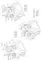
- FIG. 1An example of a conventional upper control arm adjustment system is shown in FIG. 1, and is exemplary of the type of system used on the lower control arm of the 1999 model TOYOTA TUNDRA truck.
- a bracket 1is mounted upon a portion of the vehicle's frame 2 for receiving one of the attachment points of the lower control arm (not shown).
- a bolt 3is placed through a pair of openings 4 , 5 , provided on the bracket 1 .
- the bolt 3is received in a bushing 3 a .
- a pair of nuts 6 , 7respectively, when tightened against the bracket 1 secure bolt 3 within the confines of the pair of openings 4 , 5 .
- a pair of rotatable cams 8 , 9are provided on the outer surfaces of the bracket 1 , with the bolt 3 extending through openings (not shown) provided on the pair of cams 8 , 9 .
- the pair of cams 8 , 9permit the relative movement of the bushing 3 a within the pair of openings or slots 4 , 5 , thus allowing for the adjustment of the pivot axis of the lower control arm.
- On both sides of the pair of cams 8 , 9are a set of paired cam guides 10 , 11 , 12 , 13 , respectively, which are typically welded to the frame 2 .
- the pair of cams 8 , 9are centered between the cam guides 10 , 11 , 12 , 13 , respectively.
- the bushing 3 amoves in a cross-car (i.e., inboard-outboard) direction in the pair of slots 4 , 5 , respectively, thus changing the relative position of the lower control arm with respect to the bracket 1 so as to enable the establishment of the proper pivot axis of the lower control arm.
- At least one of the objects of the present inventionis to provide such an upper control arm adjustment system.
- an upper control arm adjustment system for an automobile suspension systemcomprising:
- bracket memberhaving an area defining an aperture, the bracket member having a pair of spaced and opposed finger members extending upwardly away from the aperture;
- an upper control arm adjustment system for an automobile suspension systemcomprising:
- bracket memberhaving an area defining an aperture, the bracket member having a pair of spaced and opposed finger members extending upwardly away from the aperture;
- an upper control arm adjustment system for an automobile suspension systemcomprising:
- first bracket memberhaving an area defining an aperture, the first bracket member having a pair of spaced and opposed finger members extending upwardly away from the aperture;
- the second bracket memberhaving an area defining an aperture, the second bracket member having a pair of spaced and opposed finger members extending upwardly away from the aperture;
- FIG. 1is a partial perspective view of an upper control arm adjustment system, in accordance with the prior art
- FIG. 2is a partial perspective view of an upper control arm adjustment system, in accordance with one embodiment of the present invention.
- FIG. 3is a partial perspective view of the upper control arm adjustment system depicted in FIG. 2, with the bolt in its full positive caster position (i.e., full inboard position), in accordance with one embodiment of the present invention.
- FIG. 4is a partial perspective view of the upper control arm adjustment system depicted in FIG. 2, with the bolt in its full negative caster position (i.e., full outboard position), in accordance with one embodiment of the present invention.
- FIG. 5is an exploded view of an upper control arm adjustment system, in accordance with one embodiment of the present invention.
- FIG. 6is a partial perspective view of the upper control arm adjustment system depicted in FIG. 5, in accordance with one embodiment of the present invention.
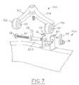
- FIG. 7is an exploded view of an upper control arm adjustment system, in accordance with an alternative embodiment of the present invention.
- FIG. 8is a partial perspective view of the upper control arm adjustment system depicted in FIG. 7, in accordance with an alternative embodiment of the present invention.
- the present inventionis directed primarily to an upper control arm adjustment system, it should be noted that the present invention can be practiced with any number of different types of mechanisms and assemblies which require the adjustment of pivot points and relative positions.
- the present inventionproposes a new and improved upper control arm adjustment system that replaces the conventional cam and cam guide system with a lever/indexing finger system.
- the system 20includes a bracket member 22 , a pair of spaced and opposed indexing fingers 24 , 26 , respectively, and a position adjustment system 28 .
- the position adjustment system 28includes an elongated member 30 , such as a bolt, which extends through an aperture or slot 32 formed in the bracket member 22 , a manipulation member 34 for rotating the elongated member 30 relative to the slot 32 , a locking member 36 (e.g., a nut) for ensuring that the elongated member 30 does not fall out of the slot 32 , and a lever member 38 which enables the elongated member 30 to move relative to the slot 32 when the manipulation member 34 is rotated.
- the bracket memberis provided with a second pair of spaced and opposed indexing fingers 40 , 42 , respectively, and a second lever member 44 .
- the bracket member 22is preferably mounted to a frame member 46 of the automobile.
- the system 20includes a second bracket member 48 , with identical characteristics as the first bracket member 22 , as well as a second position adjustment system (not shown).
- a second bracket member 48with identical characteristics as the first bracket member 22 , as well as a second position adjustment system (not shown).
- one attachment point of an upper control armwould be rotatably connected to the bolt 30 , with the other attachment point of the upper control arm being rotatably connected to the bolt (not shown) of the second bracket member 48 .
- the manipulation member 34is selectively rotated either clockwise or counterclockwise in order to adjust the position of the bolt 30 relative to the slot 32 .
- the lever members 38 and 44will contact indexing fingers 24 , 26 , 40 , 42 , respectively, thus causing the bolt to either move inboard or outboard with respect to the slot 32 , depending on the direction of rotation.
- the bolt 30is shown in its full positive caster position (i.e., full inboard position) which was caused by rotating the manipulation member in a clockwise position, thus causing lever members 38 and 44 to contact indexing fingers 26 and 42 , respectively, which in turn caused the bolt 30 to move relative to the slot 32 to the position shown.
- the bolt 30is shown in its full negative caster position (i.e., full outboard position) which was caused by rotating the manipulation member in a counterclockwise position, thus causing lever members 38 and 44 to contact indexing 10 fingers 24 and 40 , respectively, which in turn caused the bolt 30 to move relative to the slot 32 to the position shown.
- FIG. 5there is shown an exploded view of an upper control arm adjustment system, in accordance with one embodiment of the present invention.
- an upper control arm 100is shown in proximity to the upper control arm attachment system 20 .
- the upper control armtypically includes two arms 102 , 104 , respectively, terminating in two attachment points 106 , 108 respectively.
- the attachment points 106 , 108typically have slots 110 , 112 , respectively, for receiving various structures, such as elongated members.
- bracket member 22is shown, it should be noted that typically each attachment point of the control arm is associated with its own individual bracket member.
- attachment point 108is lowered into the interior portion of bracket member 22 so at to align slot 110 with slots 32 .
- bolt 30through which lever 38 is received, is then threaded through slots 32 and slot 110 and then through lever 44 whereupon a locking member 36 (e.g., a locking nut) is then secured to the distal end of bolt 30 so as to secure the upper control arm 100 to the upper control arm adjustment system 20 .
- a locking member 36e.g., a locking nut
- the locking member 36is loosened slightly and the manipulation member 34 is turned either clockwise or counterclockwise so as to cause levers 38 and/or 44 to contact indexing fingers 24 , 26 , 40 , 42 , respectively, which then causes bolt 30 to move within slots 32 so as to change the relative position of bolt 30 with respect to slots 32 . In this manner, the pivot point of the upper control arm 100 can be adjusted.
- FIG. 6there is shown a partial perspective view of the upper control arm adjustment system depicted in FIG. 5, in accordance with one embodiment of the present invention.
- the system 20is shown in its fully assembled state, with the attachment point of the upper control arm removed for purposes of clarity.
- FIG. 7there is shown an exploded view of an upper control arm adjustment system 200 , in accordance with an alternative embodiment of the present invention.
- the primary difference between this embodiment and the embodiment depicted in FIG. 5is the use of a cam device 300 .
- the bolt 30is received in the cam device 300 .
- the operation of the alternative system 200 as a wholeis substantially the same as previously described. Therefore, in this case, it is actually the cam device 300 that is moved relative to the slots 32 , whereupon the change in the pivot point of the upper control arm is accomplished.
- FIG. 8there is shown a partial perspective view of the upper control arm adjustment system depicted in FIG. 7, in accordance with an alternative embodiment of the present invention.
- the system 200is shown in its fully assembled state, with the attachment point of the upper control arm removed for purposes of clarity.
Landscapes
- Engineering & Computer Science (AREA)
- Mechanical Engineering (AREA)
- Vehicle Body Suspensions (AREA)
Abstract
Description
Claims (11)
Priority Applications (1)
| Application Number | Priority Date | Filing Date | Title |
|---|---|---|---|
| US09/725,992US6457728B1 (en) | 2000-11-29 | 2000-11-29 | Upper control arm adjustment system |
Applications Claiming Priority (1)
| Application Number | Priority Date | Filing Date | Title |
|---|---|---|---|
| US09/725,992US6457728B1 (en) | 2000-11-29 | 2000-11-29 | Upper control arm adjustment system |
Publications (2)
| Publication Number | Publication Date |
|---|---|
| US20020063005A1 US20020063005A1 (en) | 2002-05-30 |
| US6457728B1true US6457728B1 (en) | 2002-10-01 |
Family
ID=24916770
Family Applications (1)
| Application Number | Title | Priority Date | Filing Date |
|---|---|---|---|
| US09/725,992Expired - LifetimeUS6457728B1 (en) | 2000-11-29 | 2000-11-29 | Upper control arm adjustment system |
Country Status (1)
| Country | Link |
|---|---|
| US (1) | US6457728B1 (en) |
Cited By (14)
| Publication number | Priority date | Publication date | Assignee | Title |
|---|---|---|---|---|
| US20050051989A1 (en)* | 2003-09-06 | 2005-03-10 | Hyundai Mobis, Co., Ltd. | Suspension assembly applicable to both manual and power steering systems |
| US20050146105A1 (en)* | 2004-01-06 | 2005-07-07 | Soles Peter J. | Wheel alignment arrangements for vehicles |
| WO2005076956A3 (en)* | 2004-02-06 | 2007-03-01 | Volvo Trucks North America Inc | Adjustment arrangement in a suspension hanger assembly |
| US20080254281A1 (en)* | 2004-10-22 | 2008-10-16 | Dow Global Technologies Inc. | Microlayer Structures and Methods |
| US7891679B2 (en) | 2006-08-09 | 2011-02-22 | Volvo Group North America, Llc | Adjustment arrangement in a suspension hanger assembly |
| CN103825536A (en)* | 2012-11-19 | 2014-05-28 | 富昱能源科技(昆山)有限公司 | Bracket |
| US20150084300A1 (en)* | 2013-09-20 | 2015-03-26 | Ford Global Technologies, Llc | Chassis module and camber angle adjustment |
| US20170274717A1 (en)* | 2014-09-05 | 2017-09-28 | Jaguar Land Rover Limited | Joint locator |
| US10023018B2 (en)* | 2014-01-20 | 2018-07-17 | Renault S.A.S. | Fusible linking yoke between the suspension arm and the engine cradle |
| US10086874B2 (en)* | 2016-11-30 | 2018-10-02 | Ford Global Technologies, Llc | Modular vehicle platform and related methods |
| US10532621B2 (en)* | 2016-03-16 | 2020-01-14 | Komatsu Ltd. | Mounting structure for suspension arm, and working vehicle |
| US10994580B1 (en) | 2019-08-14 | 2021-05-04 | Northstar Manufacturing Co., Inc. | Adjustable ball joint coupling |
| US11254176B1 (en) | 2019-08-14 | 2022-02-22 | Northstar Manufacturing Co., Inc. | Adjustable ball joint coupling |
| US11845316B1 (en) | 2021-09-08 | 2023-12-19 | Northstar Manufacturing Co., Inc. | Adjustable pivot joint for vehicle suspensions |
Families Citing this family (14)
| Publication number | Priority date | Publication date | Assignee | Title |
|---|---|---|---|---|
| CN100465002C (en)* | 2002-05-31 | 2009-03-04 | 麦格纳国际公司 | Hydroformed control arms |
| US7438147B2 (en) | 2003-04-02 | 2008-10-21 | Yamaha Hatsudoki Kabushiki Kaisha | Transmission for off-road vehicle |
| US7506712B2 (en)* | 2003-04-02 | 2009-03-24 | Yamaha Hatsudoki Kabushiki Kaisha | Off road vehicle with air intake system |
| US7650959B2 (en)* | 2003-04-02 | 2010-01-26 | Yamaha Hatsudoki Kabushiki Kaisha | Frame arrangement for off-road vehicle |
| US7357211B2 (en)* | 2003-04-02 | 2008-04-15 | Yamaha Hatsudoki Kabushiki Kaisha | Steering system for off-road vehicle |
| US7287619B2 (en) | 2003-04-02 | 2007-10-30 | Yamaha Hatsudoki Kabushiki Kaisha | Air intake system for off-road vehicle |
| US7510199B2 (en)* | 2003-04-02 | 2009-03-31 | Yamaha Hatsudoki Kabushiki Kaisha | Off-road vehicle with wheel suspension |
| US7367417B2 (en)* | 2003-04-02 | 2008-05-06 | Yamaha Hatsudoki Kabushiki Kaisha | Floor arrangement for off-road vehicle |
| US8485541B2 (en)* | 2010-06-03 | 2013-07-16 | Nicola Pozio | Suspension for a tricycle |
| FR2982531A1 (en)* | 2011-11-15 | 2013-05-17 | Peugeot Citroen Automobiles Sa | Adjustable connecting device for connecting wheel support to suspension arm of vehicle, has body including slot, and slider including bore, where bore and slot receive screw and nut, and/or maintain position of slider relative to body |
| DE102017211393B4 (en)* | 2017-07-04 | 2019-10-24 | Zf Friedrichshafen Ag | Arrangement for connecting a suspension link to a wheel carrier |
| DE102017115248B4 (en)* | 2017-07-07 | 2020-03-12 | Saf-Holland Gmbh | System for fixing a pivot bolt to a vehicle frame, vehicle frame for connecting a pivot bolt and method for mounting a pivot bolt on a vehicle frame |
| JP6863207B2 (en)* | 2017-09-29 | 2021-04-21 | トヨタ自動車株式会社 | Lower arm support bracket and lower arm support mechanism provided with this |
| USD1084588S1 (en)* | 2023-03-06 | 2025-07-15 | Traxxas, L.P. | Model vehicle work stand locking arm |
Citations (24)
| Publication number | Priority date | Publication date | Assignee | Title |
|---|---|---|---|---|
| US2263628A (en)* | 1939-11-01 | 1941-11-25 | Robert C Hinton | Adjustment tool for individual front wheel suspensions |
| US2855212A (en) | 1956-11-05 | 1958-10-07 | Flxible Company | Independent front wheel torsion suspension for vehicles |
| US3124370A (en) | 1964-03-10 | traugott | ||
| US4030737A (en) | 1975-08-01 | 1977-06-21 | Bridges Alvin C | Adjustable mounting for pivotal wheel support |
| US4267896A (en) | 1980-02-04 | 1981-05-19 | Hendriksen Errol C | Method and apparatus for aligning automobile suspension members |
| US4313617A (en)* | 1979-03-28 | 1982-02-02 | Toyota Jidosha Kogyo Kabushiki Kaisha | Camber adjusting device in strut type suspension system |
| US4616845A (en) | 1985-01-18 | 1986-10-14 | Specialty Products, Inc. | Toe adjustment apparatus |
| US4635958A (en)* | 1984-07-18 | 1987-01-13 | Toyota Jidosha Kabushiki Kaisha | Automobile suspensions |
| US4733884A (en) | 1986-08-04 | 1988-03-29 | Specialty Products Company | Camber adjustemnt device |
| US4736964A (en) | 1986-12-29 | 1988-04-12 | Specktor Gerald A | Locking cam for adjustment of automobile wheel alignment |
| US4754991A (en) | 1986-09-03 | 1988-07-05 | Jordan Robert O | Method and buffer apparatus for preventing corrosion in dynamic load bearing assembly |
| US4869527A (en) | 1987-07-17 | 1989-09-26 | Coddens Douglas W | Vehicle wheel alignment device |
| US4973075A (en)* | 1989-12-04 | 1990-11-27 | Chrysler Corporation | Independent suspension toe and camber adjustment system |
| US5052711A (en) | 1990-05-18 | 1991-10-01 | A.O. Smith Corporation | Vehicle alignment and verification system |
| US5284353A (en) | 1989-12-15 | 1994-02-08 | Yorozu Manufacturing Corporation | Independent suspension |
| US5286052A (en) | 1992-11-23 | 1994-02-15 | Chrysler Corporation | Vehicle suspension with floating upper arm |
| US5301977A (en) | 1992-11-02 | 1994-04-12 | Specialty Products Company | Method and apparatus for adjusting toe and/or camber |
| US5332255A (en) | 1991-04-19 | 1994-07-26 | Dina Autobuses, S.A. De C.V. | Front suspension assembly |
| US5398411A (en) | 1991-12-10 | 1995-03-21 | Honda Giken Kogyo Kabushiki Kaisha | Process for producing suspension member for vehicle |
| US5775719A (en) | 1997-03-21 | 1998-07-07 | General Motors Corporation | Control arm alignment mechanism |
| US5826894A (en) | 1997-11-20 | 1998-10-27 | Chrysler Corporation | Alignment cam position limiter |
| US5839742A (en) | 1994-10-12 | 1998-11-24 | Holt; Laurence J. | Cam operated vehicle suspension system |
| US5967536A (en) | 1997-08-22 | 1999-10-19 | Spivey; Bart W. | Adjustable front suspension replacement kit |
| US6003886A (en) | 1998-10-28 | 1999-12-21 | Suspension Technologies, Inc. | Adjustable vehicle-lowering rear lateral arm |
- 2000
- 2000-11-29USUS09/725,992patent/US6457728B1/ennot_activeExpired - Lifetime
Patent Citations (25)
| Publication number | Priority date | Publication date | Assignee | Title |
|---|---|---|---|---|
| US3124370A (en) | 1964-03-10 | traugott | ||
| US2263628A (en)* | 1939-11-01 | 1941-11-25 | Robert C Hinton | Adjustment tool for individual front wheel suspensions |
| US2855212A (en) | 1956-11-05 | 1958-10-07 | Flxible Company | Independent front wheel torsion suspension for vehicles |
| US4030737A (en) | 1975-08-01 | 1977-06-21 | Bridges Alvin C | Adjustable mounting for pivotal wheel support |
| US4313617A (en)* | 1979-03-28 | 1982-02-02 | Toyota Jidosha Kogyo Kabushiki Kaisha | Camber adjusting device in strut type suspension system |
| US4267896A (en) | 1980-02-04 | 1981-05-19 | Hendriksen Errol C | Method and apparatus for aligning automobile suspension members |
| US4635958A (en)* | 1984-07-18 | 1987-01-13 | Toyota Jidosha Kabushiki Kaisha | Automobile suspensions |
| US4616845A (en) | 1985-01-18 | 1986-10-14 | Specialty Products, Inc. | Toe adjustment apparatus |
| US4733884A (en) | 1986-08-04 | 1988-03-29 | Specialty Products Company | Camber adjustemnt device |
| US4733884B1 (en) | 1986-08-04 | 1989-04-18 | ||
| US4754991A (en) | 1986-09-03 | 1988-07-05 | Jordan Robert O | Method and buffer apparatus for preventing corrosion in dynamic load bearing assembly |
| US4736964A (en) | 1986-12-29 | 1988-04-12 | Specktor Gerald A | Locking cam for adjustment of automobile wheel alignment |
| US4869527A (en) | 1987-07-17 | 1989-09-26 | Coddens Douglas W | Vehicle wheel alignment device |
| US4973075A (en)* | 1989-12-04 | 1990-11-27 | Chrysler Corporation | Independent suspension toe and camber adjustment system |
| US5284353A (en) | 1989-12-15 | 1994-02-08 | Yorozu Manufacturing Corporation | Independent suspension |
| US5052711A (en) | 1990-05-18 | 1991-10-01 | A.O. Smith Corporation | Vehicle alignment and verification system |
| US5332255A (en) | 1991-04-19 | 1994-07-26 | Dina Autobuses, S.A. De C.V. | Front suspension assembly |
| US5398411A (en) | 1991-12-10 | 1995-03-21 | Honda Giken Kogyo Kabushiki Kaisha | Process for producing suspension member for vehicle |
| US5301977A (en) | 1992-11-02 | 1994-04-12 | Specialty Products Company | Method and apparatus for adjusting toe and/or camber |
| US5286052A (en) | 1992-11-23 | 1994-02-15 | Chrysler Corporation | Vehicle suspension with floating upper arm |
| US5839742A (en) | 1994-10-12 | 1998-11-24 | Holt; Laurence J. | Cam operated vehicle suspension system |
| US5775719A (en) | 1997-03-21 | 1998-07-07 | General Motors Corporation | Control arm alignment mechanism |
| US5967536A (en) | 1997-08-22 | 1999-10-19 | Spivey; Bart W. | Adjustable front suspension replacement kit |
| US5826894A (en) | 1997-11-20 | 1998-10-27 | Chrysler Corporation | Alignment cam position limiter |
| US6003886A (en) | 1998-10-28 | 1999-12-21 | Suspension Technologies, Inc. | Adjustable vehicle-lowering rear lateral arm |
Cited By (18)
| Publication number | Priority date | Publication date | Assignee | Title |
|---|---|---|---|---|
| US20050051989A1 (en)* | 2003-09-06 | 2005-03-10 | Hyundai Mobis, Co., Ltd. | Suspension assembly applicable to both manual and power steering systems |
| US7052024B2 (en)* | 2003-09-06 | 2006-05-30 | Hyundai Mobis, Co., Ltd. | Suspension assembly applicable to both manual and power steering systems |
| US20050146105A1 (en)* | 2004-01-06 | 2005-07-07 | Soles Peter J. | Wheel alignment arrangements for vehicles |
| US7083176B2 (en)* | 2004-01-06 | 2006-08-01 | General Motors Corporation | Wheel alignment arrangements for vehicles |
| WO2005076956A3 (en)* | 2004-02-06 | 2007-03-01 | Volvo Trucks North America Inc | Adjustment arrangement in a suspension hanger assembly |
| US20080254281A1 (en)* | 2004-10-22 | 2008-10-16 | Dow Global Technologies Inc. | Microlayer Structures and Methods |
| US8043696B2 (en) | 2004-10-22 | 2011-10-25 | Dow Global Technologies Llc | Microlayer structures and methods |
| US7891679B2 (en) | 2006-08-09 | 2011-02-22 | Volvo Group North America, Llc | Adjustment arrangement in a suspension hanger assembly |
| CN103825536A (en)* | 2012-11-19 | 2014-05-28 | 富昱能源科技(昆山)有限公司 | Bracket |
| US8833712B2 (en)* | 2012-11-19 | 2014-09-16 | Hong Fu Jin Precision Industry (Shenzhen) Co., Ltd. | Pole assembly |
| US20150084300A1 (en)* | 2013-09-20 | 2015-03-26 | Ford Global Technologies, Llc | Chassis module and camber angle adjustment |
| US10023018B2 (en)* | 2014-01-20 | 2018-07-17 | Renault S.A.S. | Fusible linking yoke between the suspension arm and the engine cradle |
| US20170274717A1 (en)* | 2014-09-05 | 2017-09-28 | Jaguar Land Rover Limited | Joint locator |
| US10532621B2 (en)* | 2016-03-16 | 2020-01-14 | Komatsu Ltd. | Mounting structure for suspension arm, and working vehicle |
| US10086874B2 (en)* | 2016-11-30 | 2018-10-02 | Ford Global Technologies, Llc | Modular vehicle platform and related methods |
| US10994580B1 (en) | 2019-08-14 | 2021-05-04 | Northstar Manufacturing Co., Inc. | Adjustable ball joint coupling |
| US11254176B1 (en) | 2019-08-14 | 2022-02-22 | Northstar Manufacturing Co., Inc. | Adjustable ball joint coupling |
| US11845316B1 (en) | 2021-09-08 | 2023-12-19 | Northstar Manufacturing Co., Inc. | Adjustable pivot joint for vehicle suspensions |
Also Published As
| Publication number | Publication date |
|---|---|
| US20020063005A1 (en) | 2002-05-30 |
Similar Documents
| Publication | Publication Date | Title |
|---|---|---|
| US6457728B1 (en) | Upper control arm adjustment system | |
| US6446991B1 (en) | Lower control arm adjustment system | |
| US5498018A (en) | Wheel suspension | |
| AU661514B2 (en) | Alignment mechanism for vehicle suspensions | |
| RU2514951C2 (en) | Suspension of transport facility | |
| US6116627A (en) | Front suspension | |
| KR100335952B1 (en) | Front suspension assembly of cars | |
| US5558360A (en) | Vehicle suspension system for a steerable drive wheel | |
| US4515391A (en) | Vehicle suspension with lateral member | |
| EP0623077B1 (en) | Suspension system for vehicle | |
| US7077407B2 (en) | Interconnected suspension | |
| JPS59199312A (en) | Rear wheel suspension device for vehicle | |
| JPS6331812A (en) | Suspension device for automobile | |
| KR20050018130A (en) | control arm structure to adjust camber and tread for a vehicle | |
| KR0136258B1 (en) | Suspension apparatus | |
| KR100207104B1 (en) | Steering wheel suspension for automobile | |
| KR100471826B1 (en) | a suspension system of vehicles | |
| KR19980031517U (en) | Vehicle suspension with camber and caster adjustment | |
| KR200237453Y1 (en) | Wishbone type steering system of automobile | |
| KR20090003576A (en) | Rear Suspension Structure of Vehicle | |
| KR100452285B1 (en) | Control arm for suspension | |
| KR200147905Y1 (en) | Camber shim of vehicle with escape prevention structure | |
| JPH05169943A (en) | Suspension device of vehicle | |
| KR100427332B1 (en) | Rear suspension system for vehicles | |
| JP2985896B2 (en) | Rear suspension |
Legal Events
| Date | Code | Title | Description |
|---|---|---|---|
| AS | Assignment | Owner name:DAIMLERCHRYSLER CORPORATION, MICHIGAN Free format text:ASSIGNMENT OF ASSIGNORS INTEREST;ASSIGNOR:KLAIS, MATTHEW E.;REEL/FRAME:011991/0197 Effective date:20001120 | |
| STCF | Information on status: patent grant | Free format text:PATENTED CASE | |
| FPAY | Fee payment | Year of fee payment:4 | |
| AS | Assignment | Owner name:WILMINGTON TRUST COMPANY, DELAWARE Free format text:GRANT OF SECURITY INTEREST IN PATENT RIGHTS - FIRST PRIORITY;ASSIGNOR:CHRYSLER LLC;REEL/FRAME:019773/0001 Effective date:20070803 Owner name:WILMINGTON TRUST COMPANY,DELAWARE Free format text:GRANT OF SECURITY INTEREST IN PATENT RIGHTS - FIRST PRIORITY;ASSIGNOR:CHRYSLER LLC;REEL/FRAME:019773/0001 Effective date:20070803 | |
| AS | Assignment | Owner name:WILMINGTON TRUST COMPANY, DELAWARE Free format text:GRANT OF SECURITY INTEREST IN PATENT RIGHTS - SECOND PRIORITY;ASSIGNOR:CHRYSLER LLC;REEL/FRAME:019767/0810 Effective date:20070803 Owner name:WILMINGTON TRUST COMPANY,DELAWARE Free format text:GRANT OF SECURITY INTEREST IN PATENT RIGHTS - SECOND PRIORITY;ASSIGNOR:CHRYSLER LLC;REEL/FRAME:019767/0810 Effective date:20070803 | |
| AS | Assignment | Owner name:DAIMLERCHRYSLER COMPANY LLC, MICHIGAN Free format text:CHANGE OF NAME;ASSIGNOR:DAIMLERCHRYSLER CORPORATION;REEL/FRAME:021779/0793 Effective date:20070329 | |
| AS | Assignment | Owner name:CHRYSLER LLC, MICHIGAN Free format text:CHANGE OF NAME;ASSIGNOR:DAIMLERCHRYSLER COMPANY LLC;REEL/FRAME:021826/0001 Effective date:20070727 | |
| AS | Assignment | Owner name:US DEPARTMENT OF THE TREASURY, DISTRICT OF COLUMBI Free format text:GRANT OF SECURITY INTEREST IN PATENT RIGHTS - THIR;ASSIGNOR:CHRYSLER LLC;REEL/FRAME:022259/0188 Effective date:20090102 Owner name:US DEPARTMENT OF THE TREASURY,DISTRICT OF COLUMBIA Free format text:GRANT OF SECURITY INTEREST IN PATENT RIGHTS - THIR;ASSIGNOR:CHRYSLER LLC;REEL/FRAME:022259/0188 Effective date:20090102 | |
| AS | Assignment | Owner name:CHRYSLER LLC, MICHIGAN Free format text:RELEASE BY SECURED PARTY;ASSIGNOR:US DEPARTMENT OF THE TREASURY;REEL/FRAME:022902/0310 Effective date:20090608 Owner name:CHRYSLER LLC,MICHIGAN Free format text:RELEASE BY SECURED PARTY;ASSIGNOR:US DEPARTMENT OF THE TREASURY;REEL/FRAME:022902/0310 Effective date:20090608 | |
| AS | Assignment | Owner name:CHRYSLER LLC, MICHIGAN Free format text:RELEASE OF SECURITY INTEREST IN PATENT RIGHTS - FIRST PRIORITY;ASSIGNOR:WILMINGTON TRUST COMPANY;REEL/FRAME:022910/0498 Effective date:20090604 Owner name:CHRYSLER LLC, MICHIGAN Free format text:RELEASE OF SECURITY INTEREST IN PATENT RIGHTS - SECOND PRIORITY;ASSIGNOR:WILMINGTON TRUST COMPANY;REEL/FRAME:022910/0740 Effective date:20090604 Owner name:NEW CARCO ACQUISITION LLC, MICHIGAN Free format text:ASSIGNMENT OF ASSIGNORS INTEREST;ASSIGNOR:CHRYSLER LLC;REEL/FRAME:022915/0001 Effective date:20090610 Owner name:THE UNITED STATES DEPARTMENT OF THE TREASURY, DIST Free format text:SECURITY AGREEMENT;ASSIGNOR:NEW CARCO ACQUISITION LLC;REEL/FRAME:022915/0489 Effective date:20090610 Owner name:CHRYSLER LLC,MICHIGAN Free format text:RELEASE OF SECURITY INTEREST IN PATENT RIGHTS - FIRST PRIORITY;ASSIGNOR:WILMINGTON TRUST COMPANY;REEL/FRAME:022910/0498 Effective date:20090604 Owner name:CHRYSLER LLC,MICHIGAN Free format text:RELEASE OF SECURITY INTEREST IN PATENT RIGHTS - SECOND PRIORITY;ASSIGNOR:WILMINGTON TRUST COMPANY;REEL/FRAME:022910/0740 Effective date:20090604 Owner name:NEW CARCO ACQUISITION LLC,MICHIGAN Free format text:ASSIGNMENT OF ASSIGNORS INTEREST;ASSIGNOR:CHRYSLER LLC;REEL/FRAME:022915/0001 Effective date:20090610 Owner name:THE UNITED STATES DEPARTMENT OF THE TREASURY,DISTR Free format text:SECURITY AGREEMENT;ASSIGNOR:NEW CARCO ACQUISITION LLC;REEL/FRAME:022915/0489 Effective date:20090610 | |
| AS | Assignment | Owner name:CHRYSLER GROUP LLC, MICHIGAN Free format text:CHANGE OF NAME;ASSIGNOR:NEW CARCO ACQUISITION LLC;REEL/FRAME:022919/0126 Effective date:20090610 Owner name:CHRYSLER GROUP LLC,MICHIGAN Free format text:CHANGE OF NAME;ASSIGNOR:NEW CARCO ACQUISITION LLC;REEL/FRAME:022919/0126 Effective date:20090610 | |
| FPAY | Fee payment | Year of fee payment:8 | |
| AS | Assignment | Owner name:CHRYSLER GROUP LLC, MICHIGAN Free format text:RELEASE BY SECURED PARTY;ASSIGNOR:THE UNITED STATES DEPARTMENT OF THE TREASURY;REEL/FRAME:026343/0298 Effective date:20110524 Owner name:CHRYSLER GROUP GLOBAL ELECTRIC MOTORCARS LLC, NORT Free format text:RELEASE BY SECURED PARTY;ASSIGNOR:THE UNITED STATES DEPARTMENT OF THE TREASURY;REEL/FRAME:026343/0298 Effective date:20110524 | |
| AS | Assignment | Owner name:CITIBANK, N.A., NEW YORK Free format text:SECURITY AGREEMENT;ASSIGNOR:CHRYSLER GROUP LLC;REEL/FRAME:026404/0123 Effective date:20110524 | |
| AS | Assignment | Owner name:CITIBANK, N.A., NEW YORK Free format text:SECURITY AGREEMENT;ASSIGNOR:CHRYSLER GROUP LLC;REEL/FRAME:026435/0652 Effective date:20110524 | |
| AS | Assignment | Owner name:JPMORGAN CHASE BANK, N.A., ILLINOIS Free format text:SECURITY AGREEMENT;ASSIGNOR:CHRYSLER GROUP LLC;REEL/FRAME:032384/0640 Effective date:20140207 | |
| FPAY | Fee payment | Year of fee payment:12 | |
| AS | Assignment | Owner name:FCA US LLC, MICHIGAN Free format text:CHANGE OF NAME;ASSIGNOR:CHRYSLER GROUP LLC;REEL/FRAME:035553/0356 Effective date:20141203 | |
| AS | Assignment | Owner name:FCA US LLC, FORMERLY KNOWN AS CHRYSLER GROUP LLC, Free format text:RELEASE OF SECURITY INTEREST RELEASING SECOND-LIEN SECURITY INTEREST PREVIOUSLY RECORDED AT REEL 026426 AND FRAME 0644, REEL 026435 AND FRAME 0652, AND REEL 032384 AND FRAME 0591;ASSIGNOR:CITIBANK, N.A.;REEL/FRAME:037784/0001 Effective date:20151221 | |
| AS | Assignment | Owner name:FCA US LLC (FORMERLY KNOWN AS CHRYSLER GROUP LLC), Free format text:RELEASE BY SECURED PARTY;ASSIGNOR:CITIBANK, N.A.;REEL/FRAME:042885/0255 Effective date:20170224 | |
| AS | Assignment | Owner name:FCA US LLC (FORMERLY KNOWN AS CHRYSLER GROUP LLC), Free format text:RELEASE BY SECURED PARTY;ASSIGNOR:JPMORGAN CHASE BANK, N.A.;REEL/FRAME:048177/0356 Effective date:20181113 |