US6457719B1 - Brush seal - Google Patents
Brush sealDownload PDFInfo
- Publication number
- US6457719B1 US6457719B1US09/638,224US63822400AUS6457719B1US 6457719 B1US6457719 B1US 6457719B1US 63822400 AUS63822400 AUS 63822400AUS 6457719 B1US6457719 B1US 6457719B1
- Authority
- US
- United States
- Prior art keywords
- back plate
- brush seal
- apertures
- bristles
- side plate
- Prior art date
- Legal status (The legal status is an assumption and is not a legal conclusion. Google has not performed a legal analysis and makes no representation as to the accuracy of the status listed.)
- Expired - Lifetime
Links
Images

Classifications
- F—MECHANICAL ENGINEERING; LIGHTING; HEATING; WEAPONS; BLASTING
- F16—ENGINEERING ELEMENTS AND UNITS; GENERAL MEASURES FOR PRODUCING AND MAINTAINING EFFECTIVE FUNCTIONING OF MACHINES OR INSTALLATIONS; THERMAL INSULATION IN GENERAL
- F16J—PISTONS; CYLINDERS; SEALINGS
- F16J15/00—Sealings
- F16J15/16—Sealings between relatively-moving surfaces
- F16J15/32—Sealings between relatively-moving surfaces with elastic sealings, e.g. O-rings
- F16J15/3284—Sealings between relatively-moving surfaces with elastic sealings, e.g. O-rings characterised by their structure; Selection of materials
- F16J15/3288—Filamentary structures, e.g. brush seals
Definitions
- This inventionpertains to seals for turbine engines in general and to brush seals in particular.
- Brush sealsare designed to provide a controlled leakage flow from a higher pressure region to a lower pressure region through a gap disposed between a stationary member and a rotating member.
- the sealingis providing by a plurality of bristles packed between a side plate and a back plate.
- the side plateis located on the high pressure (P H ) side of the seal and the back plate is located on the low pressure (P L ) side of the seal.
- the bristlesextend beyond the side and back plates, across the gap between the stationary and rotating members.
- a brush sealhaving a side plate, a back plate, and a bristle pack disposed between the side plate and the back plate.
- the side plateis in contact with an upstream surface of the bristle pack.
- the back plateis in contact with a downstream surface of the bristle pack.
- the back plateincludes a plurality of apertures positioned to provide a gas path through the back plate for gas exiting the bristle pack.
- the back platefurther includes an exit channel disposed in the back plate surface contiguous with the bristle pack, aligned with the apertures.
- the radial length of the side plate in contact with the bristle packis less than the radial length of the back plate in contact with the bristle pack.
- An advantage of the present inventionis that an increased durability brush seal is provided. Under normal operating conditions, traditional brush seals can prematurely deform by deflecting in the direction of the leakage flow through the seal. This type of deformation is a function of the pressure difference across the seal and more specifically the velocity of the flow passing through the bristle pack. In a traditional brush seal having a side plate radially shorter than the back plate, the velocity of the leakage flow in the region adjacent the edge of the back plate is appreciably higher than elsewhere in the bristle pack. As a result, the bristles in the region adjacent the edge of back plate are subject to the highest loading, which increases their susceptibility to deformation. In the event of such a deformation, the leakage flow rate is dramatically increased and the seal function comprised.
- the present brush sealsubstantially decreases velocity of the leakage flow in the region adjacent the edge of the back plate by providing an alternative leakage path through the back plate of the brush seal.
- the bristle loading in the region adjacent the edge of back plateis less than in prior art brush seals of which we are aware.
- leakage flow through the bristle pack region between the back plate and the sealing surfaceis also less than in prior art brush seals, thereby further reducing the loading on the bristle pack and the consequent probability of deformation.
- FIG. 1shows a diagrammatic perspective partial view of a prior art brush seal.
- FIG. 2shows a diagrammatic representation of controlled leakage through a prior art brush seal, including flow velocity vectors.
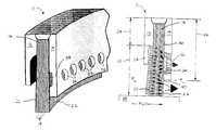
- FIG. 3shows a diagrammatic perspective partial view of a present invention brush seal.
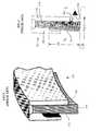
- FIG. 4shows a diagrammatic representation of controlled leakage through a present invention brush seal, including flow velocity vectors.
- the present brush seal 10includes a side plate 12 , a back plate 14 , and a bristle pack 16 disposed between the side plate 12 and the back plate 14 .
- the bristle pack 16consists of a plurality of bristles 18 attached to one another at their base.
- the side plate 12is in contact with an upstream surface 20 of the bristle pack 16
- the back plate 14is in contact with a downstream surface 22 of the bristle pack 16 .
- the radial length 24 of the side plate 12 in contact with the bristle pack 16is less than the radial length 26 of the back plate 14 in contact with the bristle pack 16 .
- the brush seal 10further includes a windage cover 28 extending out from the side plate 12 generally parallel to the bristle pack 16 , consequently forming a supply channel 30 between the windage cover 28 and the bristle pack 16 .
- the back plate 14includes a plurality of apertures 32 positioned to provide a gas path through the back plate 14 for gas exiting the bristle pack 16 .
- the apertures 32 shownare circular. Other aperture geometries may be used alternatively (e.g. slots, ovals, etc.).
- the cross-sectional area of the apertures 32is selected for the application at hand to provide the desired leakage flow rate.
- the back plate 14preferably further includes an exit channel 34 disposed in the surface 36 of the back plate 14 that is contiguous with the bristle pack 16 , aligned with the apertures 32 .
- the exit channel 34provides a circumferential path for leakage flow exiting the bristle pack 16 .
- the leakage flow through a traditional brush seal 100 (FIG. 2) and through the present invention brush seal 10 (FIG. 4)are diagrammatically shown from a high pressure side (P H ) to a low pressure side (P L ).
- P Hhigh pressure side
- P Llow pressure side
- leakage flow entering the portion of the bristle pack 104 exposed by the shorter side plate 108must travel radially within the bristle pack 104 prior to exiting over the back plate 110 of the bristle pack 104 .
- the leakage flow through the back plate 14decreases the amount of flow that must travel radially through the bristle pack 16 and subsequently exit through the portion of the bristle pack extending between the back plate 14 and the seal surface 38 . More importantly, the increased velocity flow in the region 40 adjacent the edge of the back plate 14 is diminished and therefore the associated undesirable forces as well.
Landscapes
- Engineering & Computer Science (AREA)
- General Engineering & Computer Science (AREA)
- Mechanical Engineering (AREA)
- Turbine Rotor Nozzle Sealing (AREA)
- Fuel Cell (AREA)
- Sealing Devices (AREA)
Abstract
Description
Claims (18)
Priority Applications (4)
| Application Number | Priority Date | Filing Date | Title |
|---|---|---|---|
| US09/638,224US6457719B1 (en) | 2000-08-14 | 2000-08-14 | Brush seal |
| JP2001246126AJP2002071027A (en) | 2000-08-14 | 2001-08-14 | Brush |
| EP01306900AEP1180623B1 (en) | 2000-08-14 | 2001-08-14 | Brush seal |
| DE60134093TDE60134093D1 (en) | 2000-08-14 | 2001-08-14 | brush seal |
Applications Claiming Priority (1)
| Application Number | Priority Date | Filing Date | Title |
|---|---|---|---|
| US09/638,224US6457719B1 (en) | 2000-08-14 | 2000-08-14 | Brush seal |
Publications (1)
| Publication Number | Publication Date |
|---|---|
| US6457719B1true US6457719B1 (en) | 2002-10-01 |
Family
ID=24559128
Family Applications (1)
| Application Number | Title | Priority Date | Filing Date |
|---|---|---|---|
| US09/638,224Expired - LifetimeUS6457719B1 (en) | 2000-08-14 | 2000-08-14 | Brush seal |
Country Status (4)
| Country | Link |
|---|---|
| US (1) | US6457719B1 (en) |
| EP (1) | EP1180623B1 (en) |
| JP (1) | JP2002071027A (en) |
| DE (1) | DE60134093D1 (en) |
Cited By (21)
| Publication number | Priority date | Publication date | Assignee | Title |
|---|---|---|---|---|
| US20030085525A1 (en)* | 2001-11-01 | 2003-05-08 | Boston Ian William | Deformable brush seal support |
| US20040026869A1 (en)* | 2002-08-06 | 2004-02-12 | United Technologies Corporation | Cooling arrangement for brush seal |
| US20040150165A1 (en)* | 2001-02-23 | 2004-08-05 | Grondahl Clayton M. | Seal assembly and rotary machine containing such seal |
| US20050104300A1 (en)* | 2003-10-14 | 2005-05-19 | Simon Hogg | Sealing arrangement using flexible seals |
| US7066468B2 (en)* | 2001-02-08 | 2006-06-27 | Mitsubishi Heavy Industries, Ltd. | Shaft seal and gas turbine |
| US20060267291A1 (en)* | 2005-05-25 | 2006-11-30 | Mark Addis | Brush seal assembly and method of assembling same |
| US20070069475A1 (en)* | 2005-09-29 | 2007-03-29 | General Electric Company | Pressure balanced brush seal |
| US20090050410A1 (en)* | 2007-08-22 | 2009-02-26 | Nathan Robert Berberich | Methods and systems for sealing rotating machines |
| CN101737093A (en)* | 2008-11-04 | 2010-06-16 | 西门子公司 | Annular brush sealer for turbine and turbine with the same |
| US20100164177A1 (en)* | 2008-12-30 | 2010-07-01 | Eaton Corporation | Hybrid multistage brush seal |
| US20120007318A1 (en)* | 2010-07-08 | 2012-01-12 | Ching-Pang Lee | Seal including flexible seal strips |
| US20120326392A1 (en)* | 2011-06-27 | 2012-12-27 | General Electric Company | Brush seal |
| US20120326393A1 (en)* | 2011-06-27 | 2012-12-27 | General Electric Company | Brush seal |
| US20130230393A1 (en)* | 2011-02-25 | 2013-09-05 | Mitsubishi Heavy Industries, Ltd. | Shaft seal mechanism |
| US20130249169A1 (en)* | 2007-03-24 | 2013-09-26 | Cross Manufacturing Company (1938) Limited | Seal |
| US20150285259A1 (en)* | 2014-04-05 | 2015-10-08 | Arthur John Wennerstrom | Filament-Wound Tip-Shrouded Axial Compressor or Fan Rotor System |
| US9322287B2 (en) | 2014-06-03 | 2016-04-26 | General Electric Company | Brush seal for turbine |
| US9587505B2 (en) | 2013-12-05 | 2017-03-07 | General Electric Company | L brush seal for turbomachinery application |
| US9677410B2 (en) | 2010-12-27 | 2017-06-13 | Mitsubishi Heavy Industries, Ltd. | Shaft sealing device, and rotary machine equipped therewith |
| US10662797B2 (en) | 2018-04-05 | 2020-05-26 | Raytheon Technologies Corporation | Multi-plane brush seal |
| US11035470B2 (en) | 2018-04-05 | 2021-06-15 | Raytheon Technologies Corporation | Multi-plane brush seal |
Families Citing this family (8)
| Publication number | Priority date | Publication date | Assignee | Title |
|---|---|---|---|---|
| GB0613630D0 (en) | 2006-07-10 | 2006-08-16 | Rolls Royce Plc | A seal arrangement |
| JP5028918B2 (en)* | 2006-09-11 | 2012-09-19 | 富士電機株式会社 | Sealing device for rotating objects |
| US7938403B1 (en)* | 2009-12-31 | 2011-05-10 | General Electric Company | Brush seals |
| US8454023B2 (en)* | 2011-05-10 | 2013-06-04 | General Electric Company | Retractable seal system |
| GB201115773D0 (en)* | 2011-09-13 | 2011-10-26 | Rolls Royce Plc | Brush seal |
| KR101442739B1 (en)* | 2014-04-08 | 2014-09-23 | 터보파워텍(주) | sealing apparatus with brush |
| KR101638480B1 (en)* | 2016-03-25 | 2016-07-11 | 터보파워텍(주) | brush sealing apparatus for turbine |
| KR102566198B1 (en)* | 2022-11-25 | 2023-08-11 | 터보파워텍(주) | brush sealing apparatus for turbine |
Citations (29)
| Publication number | Priority date | Publication date | Assignee | Title |
|---|---|---|---|---|
| US885032A (en) | 1907-06-24 | 1908-04-21 | Sebastian Ziani De Ferranti | Fluid packing. |
| US899319A (en) | 1906-10-08 | 1908-09-22 | Charles Algernon Parsons | Turbine. |
| US3580692A (en) | 1969-07-18 | 1971-05-25 | United Aircraft Corp | Seal construction |
| USRE30206E (en) | 1973-11-23 | 1980-02-05 | Rolls Royce (1971) Limited | Seals and method of manufacture thereof |
| GB1598926A (en) | 1978-05-24 | 1981-09-23 | Rolls Royce | Brush seals |
| US4809990A (en) | 1985-07-31 | 1989-03-07 | Motoren Und Turbinen Union Munchen Gmbh | Brush seals of ceramic material for thermal turbomachines |
| US5029875A (en) | 1989-07-07 | 1991-07-09 | Textron Inc. | Fluid seal structure |
| US5066025A (en) | 1990-06-18 | 1991-11-19 | Hanrahan Paul R | Brush seal assembly |
| US5066024A (en)* | 1988-01-29 | 1991-11-19 | Mtu Motoren- Und Turbinen-Union Munchen Gmbh | Brush-type seal |
| US5088888A (en) | 1990-12-03 | 1992-02-18 | General Electric Company | Shroud seal |
| US5090710A (en) | 1987-05-29 | 1992-02-25 | Cross Manufacturing Company (1938) Limited | Brush seals |
| WO1992005378A1 (en) | 1990-09-18 | 1992-04-02 | Cross Manufacturing Company (1938) Ltd. | Sealing devices |
| US5106104A (en)* | 1990-10-11 | 1992-04-21 | General Electric Company | Constant pressure drop multiple stage brush seal |
| US5108116A (en) | 1991-05-31 | 1992-04-28 | Allied-Signal Inc. | Laminated finger seal with logarithmic curvature |
| WO1992014951A1 (en) | 1991-02-19 | 1992-09-03 | Cross Manufacturing Company (1938) Limited | Brush seal assembly |
| US5174582A (en) | 1990-12-12 | 1992-12-29 | Rolls-Royce Plc | Sprung brush seals |
| US5181728A (en) | 1991-09-23 | 1993-01-26 | General Electric Company | Trenched brush seal |
| GB2258277A (en) | 1991-07-29 | 1993-02-03 | Europ Gas Turbines Ltd | Brush seals |
| US5308088A (en) | 1992-08-20 | 1994-05-03 | General Electric Company | Brush seal with flexible backing plate |
| US5318309A (en)* | 1992-05-11 | 1994-06-07 | General Electric Company | Brush seal |
| US5335920A (en) | 1992-08-20 | 1994-08-09 | General Electric Company | Brush seal |
| US5401036A (en) | 1993-03-22 | 1995-03-28 | Eg & G Sealol, Inc. | Brush seal device having a recessed back plate |
| US5496045A (en) | 1993-08-17 | 1996-03-05 | Rolls-Royce Plc | Brush seal with porous upstream side-plate |
| US5884918A (en) | 1996-10-04 | 1999-03-23 | Eg&G Sealol, Inc. | Brush seal with a flexible front plate |
| US5975535A (en) | 1996-10-02 | 1999-11-02 | Mtu Motoren-Und Turbinen-Union Muenchen Gmbh | Brush seal between a rotor and a stator in a turbine machine |
| US6032959A (en) | 1997-07-21 | 2000-03-07 | General Electric Company | Shingle damper brush seal |
| US6173962B1 (en)* | 1995-12-09 | 2001-01-16 | Rolls Royce Plc | Brush seal |
| US6254344B1 (en)* | 1999-01-06 | 2001-07-03 | Rolls-Royce Plc | Seal |
| US6293554B1 (en)* | 1999-05-13 | 2001-09-25 | General Electric Company | Brush seal segment having bristle damping |
Family Cites Families (2)
| Publication number | Priority date | Publication date | Assignee | Title |
|---|---|---|---|---|
| US5351971A (en)* | 1993-05-21 | 1994-10-04 | Eg&G Sealol, Inc. | Brush seal device having a floating backplate |
| GB9821927D0 (en)* | 1998-10-08 | 1998-12-02 | Rolls Royce Plc | Improved brush seal |
- 2000
- 2000-08-14USUS09/638,224patent/US6457719B1/ennot_activeExpired - Lifetime
- 2001
- 2001-08-14DEDE60134093Tpatent/DE60134093D1/ennot_activeExpired - Lifetime
- 2001-08-14EPEP01306900Apatent/EP1180623B1/ennot_activeExpired - Lifetime
- 2001-08-14JPJP2001246126Apatent/JP2002071027A/enactivePending
Patent Citations (29)
| Publication number | Priority date | Publication date | Assignee | Title |
|---|---|---|---|---|
| US899319A (en) | 1906-10-08 | 1908-09-22 | Charles Algernon Parsons | Turbine. |
| US885032A (en) | 1907-06-24 | 1908-04-21 | Sebastian Ziani De Ferranti | Fluid packing. |
| US3580692A (en) | 1969-07-18 | 1971-05-25 | United Aircraft Corp | Seal construction |
| USRE30206E (en) | 1973-11-23 | 1980-02-05 | Rolls Royce (1971) Limited | Seals and method of manufacture thereof |
| GB1598926A (en) | 1978-05-24 | 1981-09-23 | Rolls Royce | Brush seals |
| US4809990A (en) | 1985-07-31 | 1989-03-07 | Motoren Und Turbinen Union Munchen Gmbh | Brush seals of ceramic material for thermal turbomachines |
| US5090710A (en) | 1987-05-29 | 1992-02-25 | Cross Manufacturing Company (1938) Limited | Brush seals |
| US5066024A (en)* | 1988-01-29 | 1991-11-19 | Mtu Motoren- Und Turbinen-Union Munchen Gmbh | Brush-type seal |
| US5029875A (en) | 1989-07-07 | 1991-07-09 | Textron Inc. | Fluid seal structure |
| US5066025A (en) | 1990-06-18 | 1991-11-19 | Hanrahan Paul R | Brush seal assembly |
| WO1992005378A1 (en) | 1990-09-18 | 1992-04-02 | Cross Manufacturing Company (1938) Ltd. | Sealing devices |
| US5106104A (en)* | 1990-10-11 | 1992-04-21 | General Electric Company | Constant pressure drop multiple stage brush seal |
| US5088888A (en) | 1990-12-03 | 1992-02-18 | General Electric Company | Shroud seal |
| US5174582A (en) | 1990-12-12 | 1992-12-29 | Rolls-Royce Plc | Sprung brush seals |
| WO1992014951A1 (en) | 1991-02-19 | 1992-09-03 | Cross Manufacturing Company (1938) Limited | Brush seal assembly |
| US5108116A (en) | 1991-05-31 | 1992-04-28 | Allied-Signal Inc. | Laminated finger seal with logarithmic curvature |
| GB2258277A (en) | 1991-07-29 | 1993-02-03 | Europ Gas Turbines Ltd | Brush seals |
| US5181728A (en) | 1991-09-23 | 1993-01-26 | General Electric Company | Trenched brush seal |
| US5318309A (en)* | 1992-05-11 | 1994-06-07 | General Electric Company | Brush seal |
| US5308088A (en) | 1992-08-20 | 1994-05-03 | General Electric Company | Brush seal with flexible backing plate |
| US5335920A (en) | 1992-08-20 | 1994-08-09 | General Electric Company | Brush seal |
| US5401036A (en) | 1993-03-22 | 1995-03-28 | Eg & G Sealol, Inc. | Brush seal device having a recessed back plate |
| US5496045A (en) | 1993-08-17 | 1996-03-05 | Rolls-Royce Plc | Brush seal with porous upstream side-plate |
| US6173962B1 (en)* | 1995-12-09 | 2001-01-16 | Rolls Royce Plc | Brush seal |
| US5975535A (en) | 1996-10-02 | 1999-11-02 | Mtu Motoren-Und Turbinen-Union Muenchen Gmbh | Brush seal between a rotor and a stator in a turbine machine |
| US5884918A (en) | 1996-10-04 | 1999-03-23 | Eg&G Sealol, Inc. | Brush seal with a flexible front plate |
| US6032959A (en) | 1997-07-21 | 2000-03-07 | General Electric Company | Shingle damper brush seal |
| US6254344B1 (en)* | 1999-01-06 | 2001-07-03 | Rolls-Royce Plc | Seal |
| US6293554B1 (en)* | 1999-05-13 | 2001-09-25 | General Electric Company | Brush seal segment having bristle damping |
Cited By (33)
| Publication number | Priority date | Publication date | Assignee | Title |
|---|---|---|---|---|
| US7066468B2 (en)* | 2001-02-08 | 2006-06-27 | Mitsubishi Heavy Industries, Ltd. | Shaft seal and gas turbine |
| US7578509B2 (en)* | 2001-02-23 | 2009-08-25 | Cmg Tech, Llc | Seal assembly and rotary machine containing such seal |
| US20040150165A1 (en)* | 2001-02-23 | 2004-08-05 | Grondahl Clayton M. | Seal assembly and rotary machine containing such seal |
| US6840518B2 (en)* | 2001-11-01 | 2005-01-11 | Alstom Technology Ltd. | Deformable brush seal support |
| US20030085525A1 (en)* | 2001-11-01 | 2003-05-08 | Boston Ian William | Deformable brush seal support |
| US20040026869A1 (en)* | 2002-08-06 | 2004-02-12 | United Technologies Corporation | Cooling arrangement for brush seal |
| US7052015B2 (en)* | 2002-08-06 | 2006-05-30 | United Technologies Corporation | Cooling arrangement for brush seal |
| US20050104300A1 (en)* | 2003-10-14 | 2005-05-19 | Simon Hogg | Sealing arrangement using flexible seals |
| US20060267291A1 (en)* | 2005-05-25 | 2006-11-30 | Mark Addis | Brush seal assembly and method of assembling same |
| US20070069475A1 (en)* | 2005-09-29 | 2007-03-29 | General Electric Company | Pressure balanced brush seal |
| US7255352B2 (en)* | 2005-09-29 | 2007-08-14 | General Electric Company | Pressure balanced brush seal |
| US20070216106A1 (en)* | 2005-09-29 | 2007-09-20 | General Electric Company | Pressure balanced brush seal |
| US7604242B2 (en) | 2005-09-29 | 2009-10-20 | General Electric Company | Pressure balanced brush seal |
| US20130249169A1 (en)* | 2007-03-24 | 2013-09-26 | Cross Manufacturing Company (1938) Limited | Seal |
| US9915351B2 (en)* | 2007-03-24 | 2018-03-13 | Cross Manufacturing Company (1938) Limited | Seal |
| US20090050410A1 (en)* | 2007-08-22 | 2009-02-26 | Nathan Robert Berberich | Methods and systems for sealing rotating machines |
| US8256575B2 (en)* | 2007-08-22 | 2012-09-04 | General Electric Company | Methods and systems for sealing rotating machines |
| CN101737093A (en)* | 2008-11-04 | 2010-06-16 | 西门子公司 | Annular brush sealer for turbine and turbine with the same |
| US20100164177A1 (en)* | 2008-12-30 | 2010-07-01 | Eaton Corporation | Hybrid multistage brush seal |
| US20120007318A1 (en)* | 2010-07-08 | 2012-01-12 | Ching-Pang Lee | Seal including flexible seal strips |
| US9206904B2 (en)* | 2010-07-08 | 2015-12-08 | Siemens Energy, Inc. | Seal including flexible seal strips |
| US9677410B2 (en) | 2010-12-27 | 2017-06-13 | Mitsubishi Heavy Industries, Ltd. | Shaft sealing device, and rotary machine equipped therewith |
| US9593588B2 (en)* | 2011-02-25 | 2017-03-14 | Mitsubishi Heavy Industries, Ltd. | Shaft seal mechanism |
| US20130230393A1 (en)* | 2011-02-25 | 2013-09-05 | Mitsubishi Heavy Industries, Ltd. | Shaft seal mechanism |
| US20120326392A1 (en)* | 2011-06-27 | 2012-12-27 | General Electric Company | Brush seal |
| US9528384B2 (en)* | 2011-06-27 | 2016-12-27 | General Electric Company | Brush seal |
| US20120326393A1 (en)* | 2011-06-27 | 2012-12-27 | General Electric Company | Brush seal |
| US9926800B2 (en)* | 2011-06-27 | 2018-03-27 | General Electric Company | Brush seal |
| US9587505B2 (en) | 2013-12-05 | 2017-03-07 | General Electric Company | L brush seal for turbomachinery application |
| US20150285259A1 (en)* | 2014-04-05 | 2015-10-08 | Arthur John Wennerstrom | Filament-Wound Tip-Shrouded Axial Compressor or Fan Rotor System |
| US9322287B2 (en) | 2014-06-03 | 2016-04-26 | General Electric Company | Brush seal for turbine |
| US10662797B2 (en) | 2018-04-05 | 2020-05-26 | Raytheon Technologies Corporation | Multi-plane brush seal |
| US11035470B2 (en) | 2018-04-05 | 2021-06-15 | Raytheon Technologies Corporation | Multi-plane brush seal |
Also Published As
| Publication number | Publication date |
|---|---|
| EP1180623A2 (en) | 2002-02-20 |
| JP2002071027A (en) | 2002-03-08 |
| DE60134093D1 (en) | 2008-07-03 |
| EP1180623B1 (en) | 2008-05-21 |
| EP1180623A3 (en) | 2005-03-23 |
Similar Documents
| Publication | Publication Date | Title |
|---|---|---|
| US6457719B1 (en) | Brush seal | |
| US4971336A (en) | Enhanced performance brush seals | |
| US5884918A (en) | Brush seal with a flexible front plate | |
| US6811154B2 (en) | Noncontacting finger seal | |
| US6364316B1 (en) | Dual pressure balanced noncontacting finger seal | |
| US5868398A (en) | Gas turbine stator vane seal | |
| US5201530A (en) | Multi-layered brush seal | |
| US5755445A (en) | Noncontacting finger seal with hydrodynamic foot portion | |
| US5480165A (en) | Brush seal assembly | |
| EP1654484B1 (en) | Hydrodynamic brush seal | |
| US6139018A (en) | Positive pressure-actuated brush seal | |
| US7216871B1 (en) | Non-contacting seal for rotating surfaces | |
| US5308088A (en) | Brush seal with flexible backing plate | |
| US5971400A (en) | Seal assembly and rotary machine containing such seal assembly | |
| EP0453315B1 (en) | Brush seals | |
| US6352263B1 (en) | Brush seals with bristles arranged at an angle | |
| US20080018054A1 (en) | Aspirating labyrinth seal | |
| US7604242B2 (en) | Pressure balanced brush seal | |
| EP0523899A1 (en) | Fluid bearing face seal for gas turbine engines | |
| WO1998008010A9 (en) | Noncontacting finger seal | |
| US20080136115A1 (en) | Floating sealing ring | |
| US8167313B2 (en) | Seal member, assembly and method | |
| US20100054924A1 (en) | Brush seal and turbine using the same | |
| CN108979742B (en) | Turbine suction face seal assembly | |
| GB2258277A (en) | Brush seals |
Legal Events
| Date | Code | Title | Description |
|---|---|---|---|
| AS | Assignment | Owner name:UNITED TECHNOLOGIES CORPORATION, CONNECTICUT Free format text:ASSIGNMENT OF ASSIGNORS INTEREST;ASSIGNORS:FELLENSTEIN, JAMES;MCCUTCHAN, SEAN P.;HYLAND, JAMES;AND OTHERS;REEL/FRAME:011176/0080 Effective date:20000811 | |
| STCF | Information on status: patent grant | Free format text:PATENTED CASE | |
| FEPP | Fee payment procedure | Free format text:PAYOR NUMBER ASSIGNED (ORIGINAL EVENT CODE: ASPN); ENTITY STATUS OF PATENT OWNER: LARGE ENTITY | |
| FPAY | Fee payment | Year of fee payment:4 | |
| FPAY | Fee payment | Year of fee payment:8 | |
| FPAY | Fee payment | Year of fee payment:12 | |
| AS | Assignment | Owner name:RAYTHEON TECHNOLOGIES CORPORATION, MASSACHUSETTS Free format text:CHANGE OF NAME;ASSIGNOR:UNITED TECHNOLOGIES CORPORATION;REEL/FRAME:054062/0001 Effective date:20200403 | |
| AS | Assignment | Owner name:RAYTHEON TECHNOLOGIES CORPORATION, CONNECTICUT Free format text:CORRECTIVE ASSIGNMENT TO CORRECT THE AND REMOVE PATENT APPLICATION NUMBER 11886281 AND ADD PATENT APPLICATION NUMBER 14846874. TO CORRECT THE RECEIVING PARTY ADDRESS PREVIOUSLY RECORDED AT REEL: 054062 FRAME: 0001. ASSIGNOR(S) HEREBY CONFIRMS THE CHANGE OF ADDRESS;ASSIGNOR:UNITED TECHNOLOGIES CORPORATION;REEL/FRAME:055659/0001 Effective date:20200403 |