US6456884B1 - Orthotic/electrotherapy for treating contractures due to immobility - Google Patents
Orthotic/electrotherapy for treating contractures due to immobilityDownload PDFInfo
- Publication number
- US6456884B1 US6456884B1US09/528,804US52880400AUS6456884B1US 6456884 B1US6456884 B1US 6456884B1US 52880400 AUS52880400 AUS 52880400AUS 6456884 B1US6456884 B1US 6456884B1
- Authority
- US
- United States
- Prior art keywords
- orthotic device
- electrode component
- orthotic
- muscle fibers
- body parts
- Prior art date
- Legal status (The legal status is an assumption and is not a legal conclusion. Google has not performed a legal analysis and makes no representation as to the accuracy of the status listed.)
- Expired - Fee Related
Links
- 208000006111contractureDiseases0.000titleclaimsdescription83
- 238000001827electrotherapyMethods0.000titleclaimsdescription50
- 230000033001locomotionEffects0.000claimsabstractdescription55
- 210000002808connective tissueAnatomy0.000claimsabstractdescription41
- 210000001087myotubuleAnatomy0.000claimsabstractdescription40
- 230000004118muscle contractionEffects0.000claimsabstractdescription14
- 230000001225therapeutic effectEffects0.000claimsabstractdescription13
- 206010062575Muscle contractureDiseases0.000claimsdescription62
- 210000003205muscleAnatomy0.000claimsdescription55
- 230000008602contractionEffects0.000claimsdescription21
- 208000014674injuryDiseases0.000claimsdescription21
- 239000000463materialSubstances0.000claimsdescription11
- 208000027418Wounds and injuryDiseases0.000claimsdescription9
- 230000001351cycling effectEffects0.000claimsdescription9
- 230000006378damageEffects0.000claimsdescription9
- 230000008733traumaEffects0.000claimsdescription8
- 210000005036nerveAnatomy0.000claimsdescription5
- 239000000853adhesiveSubstances0.000claimsdescription4
- 230000001070adhesive effectEffects0.000claimsdescription4
- 239000005557antagonistSubstances0.000claimsdescription4
- 239000004020conductorSubstances0.000claimsdescription4
- 230000004044responseEffects0.000claimsdescription3
- 230000002051biphasic effectEffects0.000claimsdescription2
- 238000011477surgical interventionMethods0.000claimsdescription2
- 239000000556agonistSubstances0.000claims6
- 230000000926neurological effectEffects0.000claims2
- 230000005611electricityEffects0.000claims1
- 210000000245forearmAnatomy0.000description57
- 230000001965increasing effectEffects0.000description38
- 210000001519tissueAnatomy0.000description25
- 210000002414legAnatomy0.000description24
- 238000011282treatmentMethods0.000description21
- 210000002683footAnatomy0.000description20
- 210000000689upper legAnatomy0.000description18
- 239000000835fiberSubstances0.000description16
- 238000002560therapeutic procedureMethods0.000description15
- 210000003423ankleAnatomy0.000description14
- 230000000712assemblyEffects0.000description14
- 238000000429assemblyMethods0.000description14
- 230000008901benefitEffects0.000description14
- 238000000034methodMethods0.000description14
- 230000000694effectsEffects0.000description13
- 208000002193PainDiseases0.000description11
- 210000001624hipAnatomy0.000description11
- 210000000707wristAnatomy0.000description11
- 210000003414extremityAnatomy0.000description10
- 230000006870functionEffects0.000description10
- 239000011159matrix materialSubstances0.000description10
- 210000002435tendonAnatomy0.000description9
- 210000003127kneeAnatomy0.000description8
- 238000010276constructionMethods0.000description6
- 229920002457flexible plasticPolymers0.000description6
- 229920003023plasticPolymers0.000description6
- 239000004033plasticSubstances0.000description6
- 231100000241scarToxicity0.000description6
- 230000009471actionEffects0.000description5
- 230000035876healingEffects0.000description5
- 230000009251neurologic dysfunctionEffects0.000description5
- 208000015015neurological dysfunctionDiseases0.000description5
- 230000000638stimulationEffects0.000description5
- 102000008186CollagenHuman genes0.000description4
- 108010035532CollagenProteins0.000description4
- 206010030113OedemaDiseases0.000description4
- 238000013459approachMethods0.000description4
- 238000005452bendingMethods0.000description4
- 230000017531blood circulationEffects0.000description4
- 229920001436collagenPolymers0.000description4
- 238000013461designMethods0.000description4
- 230000036541healthEffects0.000description4
- 210000003141lower extremityAnatomy0.000description4
- 210000001699lower legAnatomy0.000description4
- 230000008569processEffects0.000description4
- 238000005728strengtheningMethods0.000description4
- 208000018652Closed Head injuryDiseases0.000description3
- 208000008238Muscle SpasticityDiseases0.000description3
- 208000030886Traumatic Brain injuryDiseases0.000description3
- 208000037265diseases, disorders, signs and symptomsDiseases0.000description3
- 230000005764inhibitory processEffects0.000description3
- 210000001503jointAnatomy0.000description3
- 230000003387muscularEffects0.000description3
- 230000036961partial effectEffects0.000description3
- 230000011514reflexEffects0.000description3
- 208000018198spasticityDiseases0.000description3
- 238000001356surgical procedureMethods0.000description3
- 210000001364upper extremityAnatomy0.000description3
- 206010016654FibrosisDiseases0.000description2
- 206010020852HypertoniaDiseases0.000description2
- 206010052428WoundDiseases0.000description2
- 208000005298acute painDiseases0.000description2
- 208000020538atrophic muscular diseaseDiseases0.000description2
- 210000004556brainAnatomy0.000description2
- 210000001217buttockAnatomy0.000description2
- 208000037516chromosome inversion diseaseDiseases0.000description2
- 230000001684chronic effectEffects0.000description2
- 230000004087circulationEffects0.000description2
- 238000010586diagramMethods0.000description2
- 230000003292diminished effectEffects0.000description2
- 201000010099diseaseDiseases0.000description2
- 210000002310elbow jointAnatomy0.000description2
- 230000002708enhancing effectEffects0.000description2
- 230000004761fibrosisEffects0.000description2
- 238000010438heat treatmentMethods0.000description2
- 230000002401inhibitory effectEffects0.000description2
- 210000003041ligamentAnatomy0.000description2
- 238000004519manufacturing processMethods0.000description2
- 230000013011matingEffects0.000description2
- 238000012986modificationMethods0.000description2
- 230000004048modificationEffects0.000description2
- 210000004237neck muscleAnatomy0.000description2
- 230000007383nerve stimulationEffects0.000description2
- 230000002232neuromuscularEffects0.000description2
- 230000000399orthopedic effectEffects0.000description2
- 238000000554physical therapyMethods0.000description2
- 230000002035prolonged effectEffects0.000description2
- 230000009467reductionEffects0.000description2
- 230000012191relaxation of muscleEffects0.000description2
- 230000008439repair processEffects0.000description2
- 230000000284resting effectEffects0.000description2
- 230000000717retained effectEffects0.000description2
- 230000002441reversible effectEffects0.000description2
- 238000004904shorteningMethods0.000description2
- 210000004872soft tissueAnatomy0.000description2
- 230000008961swellingEffects0.000description2
- 208000011580syndromic diseaseDiseases0.000description2
- 210000001179synovial fluidAnatomy0.000description2
- 208000007848AlcoholismDiseases0.000description1
- 208000025978Athletic injuryDiseases0.000description1
- 208000000094Chronic PainDiseases0.000description1
- 206010011985Decubitus ulcerDiseases0.000description1
- 206010051055Deep vein thrombosisDiseases0.000description1
- 206010013654Drug abuseDiseases0.000description1
- LFQSCWFLJHTTHZ-UHFFFAOYSA-NEthanolChemical compoundCCOLFQSCWFLJHTTHZ-UHFFFAOYSA-N0.000description1
- 208000005654Hip ContractureDiseases0.000description1
- 206010021639IncontinenceDiseases0.000description1
- 229920004142LEXAN™Polymers0.000description1
- 208000007101Muscle CrampDiseases0.000description1
- 206010028289Muscle atrophyDiseases0.000description1
- 208000029549Muscle injuryDiseases0.000description1
- 208000012902Nervous system diseaseDiseases0.000description1
- XOJVVFBFDXDTEG-UHFFFAOYSA-NNorphytaneNatural productsCC(C)CCCC(C)CCCC(C)CCCC(C)CXOJVVFBFDXDTEG-UHFFFAOYSA-N0.000description1
- 206010033372Pain and discomfortDiseases0.000description1
- 208000004210Pressure UlcerDiseases0.000description1
- 206010039203Road traffic accidentDiseases0.000description1
- 208000005392SpasmDiseases0.000description1
- 208000006011StrokeDiseases0.000description1
- 206010047249Venous thrombosisDiseases0.000description1
- 230000001154acute effectEffects0.000description1
- 206010001584alcohol abuseDiseases0.000description1
- 208000025746alcohol use diseaseDiseases0.000description1
- 238000002266amputationMethods0.000description1
- 206010003246arthritisDiseases0.000description1
- 230000004071biological effectEffects0.000description1
- 230000005540biological transmissionEffects0.000description1
- 230000015572biosynthetic processEffects0.000description1
- 230000003925brain functionEffects0.000description1
- 235000019504cigarettesNutrition0.000description1
- 230000007012clinical effectEffects0.000description1
- 238000002648combination therapyMethods0.000description1
- 230000006835compressionEffects0.000description1
- 238000007906compressionMethods0.000description1
- 238000001816coolingMethods0.000description1
- 238000011161developmentMethods0.000description1
- 230000018109developmental processEffects0.000description1
- 230000003467diminishing effectEffects0.000description1
- 208000035475disorderDiseases0.000description1
- 230000004064dysfunctionEffects0.000description1
- 210000003195fasciaAnatomy0.000description1
- 239000011152fibreglassSubstances0.000description1
- 230000012010growthEffects0.000description1
- 210000003128headAnatomy0.000description1
- 210000004394hip jointAnatomy0.000description1
- 238000011221initial treatmentMethods0.000description1
- 230000001788irregularEffects0.000description1
- 210000000281joint capsuleAnatomy0.000description1
- 229920001702kydexPolymers0.000description1
- 230000002045lasting effectEffects0.000description1
- 230000007774longtermEffects0.000description1
- 238000005461lubricationMethods0.000description1
- 230000020763muscle atrophyEffects0.000description1
- 201000000585muscular atrophyDiseases0.000description1
- 208000018360neuromuscular diseaseDiseases0.000description1
- 201000001119neuropathyDiseases0.000description1
- 230000007823neuropathyEffects0.000description1
- 239000002858neurotransmitter agentSubstances0.000description1
- 201000008482osteoarthritisDiseases0.000description1
- 210000005037parasympathetic nerveAnatomy0.000description1
- 230000035515penetrationEffects0.000description1
- 230000008447perceptionEffects0.000description1
- 229920002635polyurethanePolymers0.000description1
- 239000004814polyurethaneSubstances0.000description1
- 230000000750progressive effectEffects0.000description1
- 230000001681protective effectEffects0.000description1
- 230000005180public healthEffects0.000description1
- 238000005086pumpingMethods0.000description1
- 230000002829reductive effectEffects0.000description1
- 230000002787reinforcementEffects0.000description1
- 230000002040relaxant effectEffects0.000description1
- 238000007634remodelingMethods0.000description1
- 230000000391smoking effectEffects0.000description1
- 238000001228spectrumMethods0.000description1
- 208000020431spinal cord injuryDiseases0.000description1
- 230000003068static effectEffects0.000description1
- 238000003860storageMethods0.000description1
- 208000011117substance-related diseaseDiseases0.000description1
- 210000001258synovial membraneAnatomy0.000description1
- 230000008719thickeningEffects0.000description1
- 238000007395thrombosis prophylaxisMethods0.000description1
- 230000017423tissue regenerationEffects0.000description1
- 230000000472traumatic effectEffects0.000description1
- 230000008736traumatic injuryEffects0.000description1
- 230000002792vascularEffects0.000description1
- 230000003313weakening effectEffects0.000description1
Images


Classifications
- A—HUMAN NECESSITIES
- A61—MEDICAL OR VETERINARY SCIENCE; HYGIENE
- A61N—ELECTROTHERAPY; MAGNETOTHERAPY; RADIATION THERAPY; ULTRASOUND THERAPY
- A61N1/00—Electrotherapy; Circuits therefor
- A61N1/18—Applying electric currents by contact electrodes
- A61N1/32—Applying electric currents by contact electrodes alternating or intermittent currents
- A61N1/326—Applying electric currents by contact electrodes alternating or intermittent currents for promoting growth of cells, e.g. bone cells
- A—HUMAN NECESSITIES
- A61—MEDICAL OR VETERINARY SCIENCE; HYGIENE
- A61F—FILTERS IMPLANTABLE INTO BLOOD VESSELS; PROSTHESES; DEVICES PROVIDING PATENCY TO, OR PREVENTING COLLAPSING OF, TUBULAR STRUCTURES OF THE BODY, e.g. STENTS; ORTHOPAEDIC, NURSING OR CONTRACEPTIVE DEVICES; FOMENTATION; TREATMENT OR PROTECTION OF EYES OR EARS; BANDAGES, DRESSINGS OR ABSORBENT PADS; FIRST-AID KITS
- A61F5/00—Orthopaedic methods or devices for non-surgical treatment of bones or joints; Nursing devices ; Anti-rape devices
- A61F5/01—Orthopaedic devices, e.g. long-term immobilising or pressure directing devices for treating broken or deformed bones such as splints, casts or braces
- A61F5/0102—Orthopaedic devices, e.g. long-term immobilising or pressure directing devices for treating broken or deformed bones such as splints, casts or braces specially adapted for correcting deformities of the limbs or for supporting them; Ortheses, e.g. with articulations
- A61F5/0104—Orthopaedic devices, e.g. long-term immobilising or pressure directing devices for treating broken or deformed bones such as splints, casts or braces specially adapted for correcting deformities of the limbs or for supporting them; Ortheses, e.g. with articulations without articulation
- A61F5/0111—Orthopaedic devices, e.g. long-term immobilising or pressure directing devices for treating broken or deformed bones such as splints, casts or braces specially adapted for correcting deformities of the limbs or for supporting them; Ortheses, e.g. with articulations without articulation for the feet or ankles
- A—HUMAN NECESSITIES
- A61—MEDICAL OR VETERINARY SCIENCE; HYGIENE
- A61F—FILTERS IMPLANTABLE INTO BLOOD VESSELS; PROSTHESES; DEVICES PROVIDING PATENCY TO, OR PREVENTING COLLAPSING OF, TUBULAR STRUCTURES OF THE BODY, e.g. STENTS; ORTHOPAEDIC, NURSING OR CONTRACEPTIVE DEVICES; FOMENTATION; TREATMENT OR PROTECTION OF EYES OR EARS; BANDAGES, DRESSINGS OR ABSORBENT PADS; FIRST-AID KITS
- A61F5/00—Orthopaedic methods or devices for non-surgical treatment of bones or joints; Nursing devices ; Anti-rape devices
- A61F5/01—Orthopaedic devices, e.g. long-term immobilising or pressure directing devices for treating broken or deformed bones such as splints, casts or braces
- A61F5/0102—Orthopaedic devices, e.g. long-term immobilising or pressure directing devices for treating broken or deformed bones such as splints, casts or braces specially adapted for correcting deformities of the limbs or for supporting them; Ortheses, e.g. with articulations
- A61F5/0104—Orthopaedic devices, e.g. long-term immobilising or pressure directing devices for treating broken or deformed bones such as splints, casts or braces specially adapted for correcting deformities of the limbs or for supporting them; Ortheses, e.g. with articulations without articulation
- A61F5/0118—Orthopaedic devices, e.g. long-term immobilising or pressure directing devices for treating broken or deformed bones such as splints, casts or braces specially adapted for correcting deformities of the limbs or for supporting them; Ortheses, e.g. with articulations without articulation for the arms, hands or fingers
- A—HUMAN NECESSITIES
- A61—MEDICAL OR VETERINARY SCIENCE; HYGIENE
- A61F—FILTERS IMPLANTABLE INTO BLOOD VESSELS; PROSTHESES; DEVICES PROVIDING PATENCY TO, OR PREVENTING COLLAPSING OF, TUBULAR STRUCTURES OF THE BODY, e.g. STENTS; ORTHOPAEDIC, NURSING OR CONTRACEPTIVE DEVICES; FOMENTATION; TREATMENT OR PROTECTION OF EYES OR EARS; BANDAGES, DRESSINGS OR ABSORBENT PADS; FIRST-AID KITS
- A61F5/00—Orthopaedic methods or devices for non-surgical treatment of bones or joints; Nursing devices ; Anti-rape devices
- A61F5/01—Orthopaedic devices, e.g. long-term immobilising or pressure directing devices for treating broken or deformed bones such as splints, casts or braces
- A61F5/0102—Orthopaedic devices, e.g. long-term immobilising or pressure directing devices for treating broken or deformed bones such as splints, casts or braces specially adapted for correcting deformities of the limbs or for supporting them; Ortheses, e.g. with articulations
- A61F5/013—Orthopaedic devices, e.g. long-term immobilising or pressure directing devices for treating broken or deformed bones such as splints, casts or braces specially adapted for correcting deformities of the limbs or for supporting them; Ortheses, e.g. with articulations for the arms, hands or fingers
- A—HUMAN NECESSITIES
- A61—MEDICAL OR VETERINARY SCIENCE; HYGIENE
- A61F—FILTERS IMPLANTABLE INTO BLOOD VESSELS; PROSTHESES; DEVICES PROVIDING PATENCY TO, OR PREVENTING COLLAPSING OF, TUBULAR STRUCTURES OF THE BODY, e.g. STENTS; ORTHOPAEDIC, NURSING OR CONTRACEPTIVE DEVICES; FOMENTATION; TREATMENT OR PROTECTION OF EYES OR EARS; BANDAGES, DRESSINGS OR ABSORBENT PADS; FIRST-AID KITS
- A61F5/00—Orthopaedic methods or devices for non-surgical treatment of bones or joints; Nursing devices ; Anti-rape devices
- A61F5/01—Orthopaedic devices, e.g. long-term immobilising or pressure directing devices for treating broken or deformed bones such as splints, casts or braces
- A61F5/04—Devices for stretching or reducing fractured limbs; Devices for distractions; Splints
- A61F5/05—Devices for stretching or reducing fractured limbs; Devices for distractions; Splints for immobilising
- A61F5/055—Cervical collars
Definitions
- the present inventionrelates generally to the field of orthotic devices and appliances; more particularly to orthotic devices and appliances in combination with electrotherapy useful for restoring movement to a connective joint of a mammalian body; and still more particularly to orthotic devices and appliances in combination with electrotherapy used to reverse contractures due to immobility and neurological dysfunction.
- Orthotic devices and appliancescommonly referred to just as “orthotics”(in spite of the broader dictionary definition of orthotics) have been utilized for many years by physical therapists, occupational therapists, and certified orthotic fitters to assist in the rehabilitation of loss of range of motion (LROM) of patients joints and associated limbs or adjacent skeletal parts of the patients' body.
- LROMloss of range of motion
- Orthoticsas well as splints, have been designed both to maintain and to restore the range of bodily motion due to LROM.
- loss of range of motionmay, for example, be caused by traumatic injury, rehabilitation following joint or limb surgery, and contracture due to immobilization caused by neuromuscular disorders (e.g., stroke and closed head injury) and other disease processes that significantly limit a patients ability to use a joint for normal activities of daily living (ADL).
- ADLdaily living
- a first one of these two fundamentally different types of contracturemay be defined as a fixed, high resistance of muscle to passive stretch resulting from fibrosis of the muscles and joints, or from disorders of the muscle fiber resulting in LROM, for example, of a patient's arm or leg.
- Webster's Dictionarydefines “contracture” as “a permanent shortening (as of muscle, tendon and scar tissue) producing deformity or distortion.”
- This first type of contractureis usually due to trauma, injury, or surgical intervention affecting the joint, as may be typical of sports injuries and the treatment thereof.
- this collagen fiber matrixbecomes random and irregular (depicted diagrammatically in FIG. 1B hereof), and neither elongates nor stretches compared to non-traumatized collagen fibers.
- This fusing together or adhesion of connective tissue structurese.g., ligaments, tendons, synovial membrane, fascia and fibrous joint capsules
- connective tissue structurese.g., ligaments, tendons, synovial membrane, fascia and fibrous joint capsules
- Such fusing together of connective tissueis a leading cause of lags (a non-specific indictment of the motor system's failure to move the affected joint through the full available passive range) relating to tendon gliding, depending on their strategic placement in reference to structures crossing the joint.
- lagsa non-specific indictment of the motor system's failure to move the affected joint through the full available passive range
- tendon glidingdepending on their strategic placement in reference to structures crossing the joint.
- orthoticsare primarily designed to treat this first type of contracture, but have also been used to treat contractures caused by immobility and neurological dysfunction (described below).
- orthotic devicesare not, as far as is known by the present inventor, best suited for such additional purpose.
- the second and very different type of contractureresults from joint immobility—not joint-related trauma or surgical repair of a joint. Contracture resulting from immobility is simply a shortening and thickening of the connective tissue, tendons and muscles (depicted in FIG. 1C hereof) that restrict the ROM of a joint. In such situations, the muscle fibers still retain their original uniform shape and there are no adhesions or scar tissue or significantly increased joined fiber matrix junctions to break through in order to restore full range of motion.
- contractures due to immobilitydo not need a “no pain, no gain” approach to restoring the normal range of motion, and, in fact, such an approach can actually do more harm than good.
- the collagen fibers of a contracture due to immobilityare simply shorter and thicker, and will respond to appropriate stretching techniques and motion of the joint to restore LROM.
- the stretching technique usually used for contractures caused by immobilityis Range Of Motion (ROM) Therapy and the use of Low-Load Protracted Stretch/Stress (LLPS) or “extended stretch” static or dynamic orthotic devices.
- Electrotherapyhas been used extensively in the rehabilitation of joint and muscle related injury, pain, and LROM. Electrotherapy also has demonstrated other valuable healing properties.
- the wave form “rate” or frequencyrefers to the number of pulses delivered per second. Pulse rate is the number of pulses in each energy wave. Pulse width is the length of time each energy burst stays on (for example, double pulse width to double the energy in that pulse). Pulse amplitude or height of the pulse increases as the amplitude setting is increased. The total energy per pulse is determined by the amplitude and pulse width.
- TENStranscultaneous electric neuromuscular stimulation
- TENSis characterized by biphasic electric current and selected parameters. TENS has clinically demonstrated the ability to increase blood flow, reduce swelling and edema, and provide both acute and chronic pain relief. TENS is commonly used to treat back and cervical muscular and disc syndromes, arthritis, shoulder syndromes, neuropathies and many other conditions.
- Neuromuscular electrical stimulation or NMESalso provides many therapeutic benefits. NMES is characterized by a low volt stimulation targeted at motor nerves to cause a muscle contraction. Electrically controlled contraction/relaxation of muscles has been found to effectively treat a variety of musculoskeletal and vascular conditions. It is used to maintain or increase range of motion, prevent or retard disuse atrophy, muscle re-education, relaxation of muscle spasm, increase circulation, and for deep vein thrombosis prevention.
- Microcurrent therapyis characterized by a subsensory current that acts on the body's naturally occurring electrical impulses to decrease pain and facilitate the healing process.
- electrotherapyprovides symptomatic pain relief for both post surgical and post traumatic acute pain.
- Interferntial therapy or IFis characterized- by the crossing of two medium, independent frequencies which work together to effectively stimulate large impulse fibers. These frequencies interfere with the transmission of pain message at the spinal chord level. Because of these frequencies, the IF wave meets low impedance when crossing the skin to underlying tissue. This deep tissue penetration can be adjusted to stimulate parasympathetic nerve fibers for increased blood flow and edema reduction.
- High Voltage Galvanic Therapyis characterized by high volt, pulsed galvanic stimulation, and used primarily for local edema reduction through muscle pumping and through “polarity effect”. This type of electrotherapy is used to increase or maintain range of motion, to treat disuse atrophy, for muscle re-education, to increase circulation, and to treat degenerative joint disease.
- Electrotherapycan elicit very significant muscle contraction of specific muscles to entire muscle groups. On the opposite end of the spectrum, electrotherapy can be used to inhibit muscle contraction and even provide total nerve block therapy simply by directing the correct electrical wave form to the appropriate site to have the desired clinical effect. Electrotherapy has also been used to keep neurotransmitters in the muscles functioning normally until new neuropathways can be developed to reconnect the muscle groups to the brain post stroke, spinal cord injury, closed head injury, etc.
- Electrotherapyhas also been used to provide soft tissue therapy, and has been used extensively for the repair of nerves, tendons and ligaments as well as muscles. IF and electro-therapeutic applications have been used to treat contractures, re-connect damaged neuro-pathways, heal chronic wounds, and to treat incontinence.
- the U.S. Public Health Department in it's pamphlet on The Treatment of Pressure Sores cited electrotherapyhas having the greatest clinical promise of providing possible treatment breakthroughs in the treatment of chronic wounds.
- Electrotherapyis applied primarily through the use of an electrotherapy unit (device emitting a controlled electrical wave form and amplitude) through electrical connections to strategically placed electrodes placed on the body to provide electrical current to the desired site.
- an electrotherapy unitdevice emitting a controlled electrical wave form and amplitude
- a principal objective of my current inventionis accordingly to provide more clinically effective orthotics that are an alternative to the known types of orthotics currently used to treat contractures caused by immobility and the ROM stretching technique.
- the main function of my new and more effective orthotic devicesis to treat contracture due to immobility—not trauma related to surgery or injury.
- TERT with Activity Stimulus strategyi.e., flexing
- the new orthotic devices of the present inventionprovide more effective clinical treatment for LROM due to immobility by increasing the “stimulus of activity” of the affected tissue (connective and muscle fiber) rather than just holding the issue in moderately lengthened position (LLPS or “gradual extension” therapy).
- LLPSmoderately lengthened position
- Brand (1984)“It is better not to use the word stretch for what should be long-term growth. If we want to restore normal length to a tissue that has shortened after disease (or disuse), we need to reverse the process and apply the stimulus of activity, or better, the stimulus of holding the tissue in the moderately lengthened position for a significant time.” According to Brand, it will then “grow” or lengthen.
- the present orthotic devicesincrease the stimulus of activity relative to current orthotic devices which simply hold the limb and joint in an extended position for extended periods.
- patient outcomesshould be more positive based upon an increased stimulus of activity as well as providing moderate stretch for a prolonged period with the new devices.
- the cycling or repeated extension and contraction of the joint by the new devicesprovides the additional benefits of motion (activity), increased lubrication of the tissues (production of synovial fluid) facilitating movement, and muscle re-education and diminished spasticity where neurological dysfunction is present (stroke, closed head injury, MS, etc.).
- the level of activityis higher with the new devices when high tone, spasticity, or moderate to high contraction reflexes are present in the affected limb and joint.
- the new devicesare uniquely appropriate for contractures due to immobility where neurological dysfunction is present in the affected limb.
- orthotic devicesfor example, in combination with electrotherapy, useful for extending the range of angular movement between adjacent first and second skeletal body parts which have been drawn to and involuntarily held in a shortened or restricted angular position (limited to a narrow range of motion) relative to one another by contraction of muscles and connective tissue due to immobility.
- Each such orthotic devicecomprises a first orthotic device portion, a second orthotic device portion, and means interconnecting the first and second orthotic device portions for permitting relative angular motion therebetween. Included are means for establishing an initial angle between the first and second orthotic device portions.
- the orthotic deviceare means for operatively applying or connecting the first orthotic device portion to the first body part and the second orthotic device portion to the second body part after the first body part has been pivoted, by an externally applied force, to an increased angular position relative to the first body part, the first and second orthotic device portions being then set by the establishing means at the initial angular position relative to one another which corresponds to the increased angular position of the second body part relative to the first body part.
- Spring meansare connected between the first and second orthotic device portions for urging the second orthotic device portion to return to its initial angular position relative to the first orthotic device portion when the second orthotic device portion is pulled by the applied first body part through muscular contraction and/or the elastic properties of the muscles and connective tissue from the increased angular position toward the second angular position of the first body part relative to the first body part, thereby pulling the second body part back toward the increased angular position relative to the first body part.
- the spring meansare configured so that pivotal movement of the second orthotic device portion relative to the first orthotic device portion away from the increased angular position causes a restoring loading of the spring means.
- This restoring loading of the spring means and the muscular contraction and/or the elastic properties of the muscles and connective tissue of the firsts body partact against one another and cause the second body part to cycle angularly toward and away from the first angular position and the increased angular position without further external intervention, thereby causing a gradual angular loosening of the second body part relative to the first body part and ultimately positioning the second body part at the increased angular position without the application of other forces.
- the spring meansare further configured for providing substantially no or a low load spring force between the first and second orthotic device portions when the second orthotic device portion is at the initial angular position relative to the first orthotic device portion.
- the first body partcomprises the individual's upper limb part and wherein the-second body part comprises the individual's lower limb part, the limb being the individual's arm or leg.
- the first orthotic device portionincludes a first cuff and the second orthotic device portion includes a second cuff.
- the applying meansreleasably attaches the first cuff to the lower limb part and releasably attaches the second cuff to the individual's upper limb part.
- the interconnecting meanscomprise at least one stiff member having a first end region fixed to the first cuff and a second end region fixed to the second cuff and including a hinge intermediate the first and second end regions for enabling relative angular movement therebetween in a plane defined by the longitudinal axis of the limb upper and lower parts.
- Meansare included for releasably locking the hinge at any selected angular position of the first end region relative to the second end region.
- the hingemay also or alternatively include a ratchet for enabling the opening of the first end region relative to the second end region from one angle therebetween to a larger angle therebetween.
- the spring meanscomprise relative outwardly bowing and twisting of the first and second end regions of the member when the second end region of the bar is pivoted from the initial angular position relative to the first end region to a smaller angle therebetween.
- the orthotic device of the present inventioncomprises a thermal setting, flexible member having first and second regions defined by a bend line between the first and second member regions, a bend at the bend line being set by heating, bending and cooling the member at the bend line, the bend line permitting angular movement and enabling the setting of a selected angle between the first and second member regions.
- Meansare included applying or attaching the first member region to the first body part and the second orthotic device portion to the second body part after the second body part has been moved against contracture forces away from the LROM position to an initial extended range of motion (ROM) angular position relative to the first body part, the first and second member regions being then set at the initial extended range of motion position relative to one another.
- ROMextended range of motion
- the spring meansare configured for providing substantially no or a low load spring force between the first and second orthotic device portions when the second orthotic device portion is at the initial extended ROM angular position relative to the first member region.
- the first body partcomprises the individual's forearm at the wrist and the second body part comprises said individual's hand.
- the first body partcomprises the individual's lower leg at the ankle and the second body part comprises said individual's foot.
- the first body partcomprises the individual's back at the neck and the second body part comprises the individual's head.
- the first body partcomprises an upper region the individual's back and the second body part comprises a lower region of the individual's back.
- the first body partcomprises an individual's upper thigh after lower regions of the leg have been amputated and the second body part comprises a lower region of the individual's torso at the hip.
- the body partcomprises the individual's forearm at the wrist and the second body part comprises said individual's hand.
- the spring meansare provided by flexibility of the elastic member.
- the present inventionis directed systems comprising orthotic devices, for example, such as those described herein, and electrode components positioned to be effective to conduct an electrical current to at least one body part of a patient being treated.
- the orthotic devicepreferably is adapted to extend the range of angular movement between adjacent first and second skeletal body parts which have been drawn to and involuntarily held in a limited angular range of motion position relative to one another by contraction of muscle fibers and connective tissue due to immobility of one or both of said skeletal body parts.
- the electrode componentspreferably include a plurality of individual electrically conductive elements or electrodes strategically placed relative to the orthotic device, for example, in or on the orthotic device, to combine orthotic treatment and electrotherapy.
- a power sourcefor example, an electrotherapy unit, such as those of conventional design, disposable units and the like, is used to provide electrical power or energy to the electrode component so that electrical current can be provided to the desired body part or parts.
- an electrotherapy unitsuch as those of conventional design, disposable units and the like
- the orthotic devicemay be worn by the patient for several hours, the electrotherapy may be actually used for either all or a portion of the time the orthotic is worn.
- the combination of electrotherapy and an orthotic devicehas many advantages over the separate use of each modality.
- the electrotherapycan be activated through the strategic placement of a plurality of conductive elements or electrodes, for example, in or on the orthotic device to provide numerous therapeutic benefits.
- Electrotherapycan elicit partial to total muscle inhibition to allow the orthotic device to provide superior muscle stretch and to eliminate the pain and discomfort sometimes experienced by the wearing of an orthotic device.
- Muscle strengthening and reeducation, muscle contraction inhibition, increased blood flow, nerve stimulation and neuro-pathway reconstruction, and other benefitscan also be provided while the patient wears the orthotic device.
- therapeutic patient outcomes as well as patient complianceare often significantly increased.
- the electrotherapy/orthotic therapy combinationpreferably reduces the treatment time required relative to the treatment time required if each therapy is provided separately.
- FIG. 1is a pictorial diagram depicting, in diagrammatic form, the condition of typical muscle and connective tissue across a joint: FIG. 1A depicting the normal condition of a typical bundle or matrix of normal muscle and connective tissue fibers; FIG. 1B depicting the same bundle of matrix of muscle and associated connective tissue in a tangled condition associated with post-trauma conditions and showing adhesion of tile muscle and connective tissue fibers; and FIG. 1C depicting the same bundle of muscle and connective tissue fibers similar to normal muscle and connective tissue, but having become shortened as a result of immobility;
- FIG. 2is a pictorial drawing of an upper region of an individual, showing in solid lines, by way of illustrative example, the individual's arm involuntarily held in a bent position with the forearm at a high LROM angle, ⁇ 0 , with respect to the upper arm, and further showing, in phantom lines, the forearm extended at increasing angles ⁇ 1 through ⁇ 4 relative to the upper arm by application of the present orthotics invention;
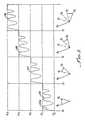
- FIG. 3is a illustrative graph in which forearm angles ⁇ 0 through ⁇ 4 of FIG. 2 are plotted against representative intervals of treatment time, depicting several exercise cycles of the individual's arm by use of the present orthotic invention to increase the bend or ROM angle between the forearm and the upper arm from ⁇ 0 to ⁇ 1 in time interval t 0 to t 1 , from ⁇ 1 to ⁇ 2 in time interval t 1 to t 2 , from ⁇ 2 to ⁇ 3 in time interval t 2 to t 3 , and from ⁇ 3 to ⁇ 4 in time interval t 3 to t 4 ;
- FIG. 4is a partially exploded, perspective drawing of a representative elbow orthotic device of the present invention which is constructed for providing gradual extension of a human arm about an elbow joint from an initial, involuntary tight angle ⁇ 0 to an extended angle ⁇ 4 which enables the individual to restore full or partial ROM of his or her arm;
- FIG. 5is a side view of the representative elbow orthotic device of FIG. 4, showing the device operationally installed onto the individual's arm in a manner bridging the individual's elbow, with the upper and lower arm held at an initial stretched ROM angle ⁇ 1 (referring to FIGS. 2 and 3 );
- FIG. 6is a longitudinal cross sectional view taken along line 6 — 6 of FIG. 5, showing upper and lower arm cuffs of the elbow orthotic device, and showing construction of an associated pair of interconnecting hinged elements which also function as orthotic device return springs;
- FIG. 7is a side view of the elbow orthotic device of FIG. 4 showing the device operationally installed onto the individual's arm with the upper and lower arm returned to initial ROM angle ⁇ 0 (referring to FIGS. 2 and 3) showing flexure of the hinged interconnecting elements;
- FIG. 8is a longitudinal cross sectional view taken along line 8 — 8 of FIG. 5, showing the pair of hinged interconnecting elements flexed and twisted outwardly at the hinge point in a manner providing a torsion spring force to urge the return of the orthotic device and the wearer's arm to the initial open position of angle ⁇ 1 ;
- FIG. 9is a transverse cross sectional drawing taken along line 9 — 9 of FIG. 5, showing the manner in which an upper end region of the orthotic device is releasably attached to the individual's upper arm;
- FIG. 10is perspective drawing of a representative one of the hinged interconnecting members, showing the first and second end portions disassembled at the hinge and showing the manner in which the hinge holds the two end portions in a fixed relative position;
- FIG. 11is a perspective drawing of an alternative lockable hinge connection between first and second device portions of a hinged interconnecting member, showing a ratchet configuration of the hinge connection which permits easier and more rapid extension between the two portions;
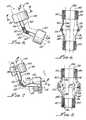
- FIG. 12is a perspective drawing of a leg- or knee-type orthotic device according to the present invention, showing features of the device and showing the device operatively installed on an individual's knee;
- FIG. 13is a perspective drawing of a hip abductor-type orthotic device in accordance with the present invention showing useful in treating hip contracture which limits the range of motion of one leg of an individual relative to the other leg of the individual, that is, when the leg is maintained by contracture crossed over the other leg;
- FIG. 14is a perspective drawing of an orthotic device in accordance with the present invention for the therapeutic treatment of contracture of a representative portion (stump) of an upper leg after the amputation of the remaining, lower portion of the leg, showing a substantially flat thermal-setting, plastic member having a first portion to be weighted down by the individual's buttocks and a second portion for detachable attachment to the stump;
- FIG. 15is a longitudinal cross sectional drawing taken along line 15 — 15 of FIG. 14 showing the manner in which the second portion of the device is manually bent (by heating of the device) in steps from an initial treatment ROM angle ⁇ 1 to an extended ROM angle ⁇ 4 ;
- FIG. 16is a perspective drawing of a foot-type orthotic device in accordance with the present invention for treating contracture of a foot with the toe pointing inwardly and showing construction of the device, including boot and bar portions and showing the boot attached to an individual's foot;
- FIG. 17is a perspective drawing of a first neck/head positioning-type orthotic device in accordance with the present invention for treating contracture of the cervical region of the spine (neck)with the head in a forward and downward direction by contracture of neck muscle fibers and connective tissue showing an elongated neck plate having attached to upper regions thereof a headband for detachably attaching to an individual's head and further showing an upper torso encircling member for retaining lower regions of the neck plate;
- FIG. 18is a perspective drawing of a back-type orthotic device in accordance with the present invention for treating a non-functional functional (forward, backward, S-shaped curvature of an individual's spine and showing a back plate and upper and lower regions of an upper torso harness for detachably attaching corresponding upper and lower regions of the device to an individual;
- FIG. 19is a perspective drawing of an upper torso-type orthotic device in accordance with the present invention for treating contracture of an individual's upper body in which the upper body is bent forward or to one side and showing construction of the device and showing means for detachable attaching the device to an individual's upper body;
- FIG. 20is a perspective drawing of an ankle-type orthotic device in accordance with the present invention for treating contracture of an individuals foot relative to his or her ankle in which the toe portion of the foot is held by contracture substantially straight down with respect to the ankle and showing construction of a boot shaped assemble and means for holding a sole of the boot against the toe portion of the foot;
- FIG. 21is a perspective drawing of a wrist-hand-finger-type orthotic device in accordance with the present invention showing the manner in which the device is constructed and detachably attached to an individual's wrist for treating contracture of an individual's hand relative to his or her wrist, and showing how the device may be used for treatment of contracture of the individual's fingers relative to his or her hand;
- FIG. 22is a perspective drawing of the wrist-hand-finger-type orthotic device depicted in FIG. 14, showing the manner in which the device is used for treating contracture of the individual's hand relative to his or her wrist and also showing how the device may be used for treatment of contracture of the individual's fingers relative to his or her hand, and further showing the manner in which graduated small-to-large finger rolls can be attached to the orthotic device for treatment of contracture of the fingers;
- FIG. 23is a side view of a head back type of orthotic device in accordance with the present invention for treating contracture of an individual's neck in a backwardly bent LROM angular contracture position, showing an upwardly-extending back member, means for detachably attaching lower regions of the back plate to an individual's upper body and a elastomeric neck cylinder disposed between upper regions of the back plate and the back of the individual's neck just below the individual's head;
- FIG. 24is a perspective drawing showing a series of neck cylinders of graduated diameter useful in the head backward orthotic device of FIG. 23 (and which are representative of the finger rolls used in the hand-type orthotic device of FIG. 22 );
- FIG. 25is a perspective drawing of a shoulder-type orthotic device further in accordance with the present invention for treating a contracture of an individual's arm relative to the individual's upper body in which the upper arm has a LROM relative to the upper body, showing construction of the device having a pocket for receiving and holding an elastomeric block for causing progressively-increasing ROM of the arm;
- FIG. 25 ais a perspective drawing showing a series of various sizes of elastomeric blocks useful in the shoulder-type orthotic device of FIG. 25;
- FIG. 26is a perspective drawing of the shoulder-type orthotic device of FIG. 25 showing the manner in which the device is detachably attached to the individual's upper arm.
- FIG. 27is a perspective drawing of an elbow-type orthotic device in combination with an electrode component and an electrotherapy unit.
- FIGS. 1-3depict the operative aspects of the present invention. It is thus believed that a brief consideration of how and why the orthotic devices of the present invention work will lead to an understanding of the orthotic devices which are described below.
- FIG. 1depicts—by way of an illustrative example for descriptive purposes, with no limitation being thereby intended or implied—a simplified diagram of a representative bundle or matrix of muscle fibers and connective tissue which may control ROM of typical joint, for example, an elbow of a human being.
- FIG. 1Adepicts a representative bundle or matrix 100 of muscle and connective tissue in a normal state or condition.
- FIG. 1Bdepicts a similar, representative bundle 102 of muscle fibers and connective tissue in a twisted and distorted, post-trauma state or condition.
- FIG. 1Cdepicts a similar, representative bundle 104 of muscle fibers and connective tissue in a shortened, but non-distorted state or condition as a result of immobility.
- the present inventionis designed and constructed to provide treatment for muscles and connective tissue on various parts of the human body skeletal system which are in the condition of bundle of muscle fibers and connective tissue depicted in FIG. 1C as a result of immobility.
- an individual 110(only the upper torso of which is shown), is depicted having a right arm or limb 112 which comprises an upper arm or upper limb portion 114 and a forearm or lower limb portion 116 .
- Forearm 116is shown in solid lines in an involuntary, slightly extended ROM angular position, ⁇ 0 , relative to upper arm 114 , by contracted muscle and/or interconnecting tissue of the configuration depicted in FIG. 1 C and caused by immobility for a protracted period of time due to one or more of the above-mentioned causes. Consequently, the afflicted individual 110 is unable by himself or herself to extend forearm 116 from this ⁇ 0 position without significant resistance and potential further injury to the afflicted joint(i.e., elbow).
- ROM angles ⁇ 1 , ⁇ 2 , ⁇ 3 and ⁇ 4are identified for descriptive purposes by ROM angles ⁇ 1 , ⁇ 2 , ⁇ 3 and ⁇ 4 .
- these increasing ROM angles ⁇ 1 , ⁇ 2 , ⁇ 3 and ⁇ 4represent increasingly greater angular ROMs of forearm 116 relative to upper arm 114 which result from the application to arm 112 of an elbow-type orthotic device in accordance with the present invention.
- FIG. 3depicts in a simplified representation the manner in which the increasing angular ROM of arm 112 as depicted in FIG. 2 may be achieved by use of the present orthotic device invention.
- FIG. 3plots angular ROMs of forearm 116 ⁇ 0 , ⁇ 1 , ⁇ 2 , ⁇ 3 and ⁇ 4 against representative periods of time, in which initial time t 0 corresponds to ROM angle ⁇ 0 , time t 1 corresponds to increased ROM angle ⁇ 1 , time t 2 corresponds to further increased ROM angle ⁇ 2 , time t 3 corresponds to still further increases angle ⁇ 3 , and time t 4 corresponds to full extension ROM angle ⁇ 4 .
- FIG. 3The objective of FIG. 3 is to depict the general situation in which the increased ROM of the individual's forearm 116 relative to upper arm 114 from ⁇ 0 to ⁇ 1 , over some time interval t 0 to t 1 , is gradually achieved through a series of forearm arm extension and contraction cycles, identified by the reference number 120 .
- Initial extension of forearm 116 to ROM angular position ⁇ 1 depicted by initial portion 120 a of cycles 120is caused by manual massage and slow extension of the forearm 116 to the point of resistance to passive stetch.
- the elbow orthotic device(described below) of the present invention is applied to arm 112 and the forearm is released. Thereafter the angular cycling of forearm 116 relative to upper arm 114 is caused by the counter action of contracture of the individual's muscle and/or connecting tissue across the elbow, which tend to pull the forearm back toward its initial shortened involuntary ROM angle ⁇ 0 relative to the upper arm, and the restoring spring force of the present orthotic device, which operates to pull or extend the forearm back to the extended ROM angle ⁇ 1 relative to upper arm 114 .
- extension-retraction cycles in sequence 120although shown regular in nature for illustrative and descriptive purposes, will, in practice, likely vary in number, length of time and magnitude, depending upon such factors as condition of the associated muscular and connective tissue (hypertonicity, spasticity, contraction reflexes, etc.) length of the immobility time, and age and general health of the patient
- the orthotic deviceis loosened or removed from arm 112 and the forearm is manually massaged and slowly stretched to an increased ROM angle ⁇ 2 .
- the orthotic device of the present inventionis retightened or reapplied to arm and is reset to angle ⁇ 2 .
- Forearm 116is released and cycles through a sequence 122 of angular contraction and extension movement in the manner just described for increasing the angular ROM of the forearm to ⁇ 1 until the angular ROM of forearm 116 is increased to angle ⁇ 2 .
- This procedureis repeated through a sequence of contraction and extension cycles 124 to increase the angular ROM of forearm 116 relative to upper arm 114 from ⁇ 2 to angle ⁇ 3 , and finally through a sequence 126 of contraction and extension cycles of forearm movement until a full ROM of the forearm, depicted by angle ⁇ 4 has been achieved.
- FIG. 4shows in exploded form a elbow- or arm-type orthotic device 140 in accordance with the present invention.
- Elbow-type orthotic device 140will be described in detail as an introduction to other types of similarly functioning orthotic devices included in the present invention and which will be described hereinbelow.
- Elbow-type orthotic device 140is specifically configured for treating contracture of arm 112 relative to elbow 142 and thereby to achieve the extended angular ROM depicted in FIGS. 2 and 3.
- elbow-type orthotic device 140comprises generally a stiff U-shaped first orthotic device upper arm portion or member 144 and a similar, stiff U-shaped second orthotic device lower arm portion or member 146 .
- First and second device portions 144 and 146are connected together in a manner enabling relative angular motion therebetween and are, in fact, hinged together by connecting means 148 , as more particularly described below.
- elbow-type orthotic device 140Further included in elbow-type orthotic device 140 are a first, upper arm padded cuff 150 and a similar, second, lower arm padded cuff 152 .
- Means for detachably attaching device 140 to arm 112comprise an adjustable upper strap 154 that is attached to device upper member 144 and an adjustable lower strap 156 that is attached to device lower member 146 .
- the means 148 for interconnecting upper and lower portions 144 and 146comprise elongate first, right side and second, left side mirror-image connecting assemblies 160 and 162 , respectively.
- right side connecting assembly 160comprises similar upper and lower elements 166 and 168 , respectively.
- left side connecting assembly 162comprises corresponding upper and lower elements 174 and 176 , respectively, adjacent ends of which are connected for relative angular movement therebetween by a lockable hinge 178 .
- right-hand lockable hinge 170includes mating first and second toothed end regions 180 and 182 of respective elements 166 and 168 .
- end regions 180 and 182When assembled and tightened together a bolt 184 and nut 186 , end regions 180 and 182 intermesh to lock upper and lower elements 166 and 168 in any selected relative angular position.
- a left lockable hinge 178is constructed in the same way, not specifically shown.
- a corresponding right-hand hinge 170 a between respective upper and lower elements 166 a and 168 ahas first and second mating regions 180 a and 182 a having teeth shaped for enabling a ramping or ratcheting action for easy opening of the upper and lower elements to greater angles therebetween, while inhibiting the closing of the elements.
- Upper and lower elements 166 a and 168 aare fastened together by a bolt 184 and nut 168 .
- a spring-type washer, for example, a Belleville washer, 188is installed on bolt 184 so that lower element 168 can be ratcheted to a greater angle position relative to upper element 166 without completely withdrawing bolt 184 from nut 186 .
- the upper end region of upper element 166is non-pivotally attached to a right-hand side region of device upper member 144 , for example, by two rivets, screws or the like 190 .
- a lower end region of lower element 168is pivotally attached to a right-hand side region of device lower member 146 by a single pivot pin or screw 192 .
- connection assembly 162Upper and lower left hand elements 174 and 176 of connection assembly 162 are attached to generally opposite sides of respective upper and lower device members 144 and 146 in the manner described for connection assembly 160 .
- upper elements 166 and 174are attached to opposite side regions of upper portion 144 in off-center positions. Assuming arrow A points to a 12 o'clock position of upper member 144 , elements 166 and 174 are attached to the upper member at about 4 o'clock and about 8 o'clock positions, respectively.
- the attachment of lower elements 168 and 176are attached to lower member 146 in a similarly offset manner. Such offset attachments enable appropriate spring action of connecting assemblies 160 and 162 , as described below.
- Upper and lower elements 166 and 168 of right connecting assembly 160are constructed, as shown in FIG. 6, which represents orthotic device 140 in the unloaded or initially set angular position ⁇ 1 of device 140 , as being slightly bowed outwardly in the region of hinge 170 from a central longitudinal axis 200 .
- elements 174 and 176 of left connecting assembly 162are constructed for being slightly bowed outwardly from axis 200 in the region of hinge 178 .
- connecting assemblies 160 and 162are thus bowed outwardly from longitudinal axis 200 in opposite directions along a transverse axis 202 .
- This configuration, as well as the offset mounting described abovecauses hinge regions of connecting assemblies 160 and 162 to be twisted outwardly in the direction of Arrows “B” (FIG. 8) to create a restoring force whenever hinges 170 and 178 are locked and device 140 is contracted in an angular direction of Arrow “C”, FIG. 7 .
- forearm 116 of arm 112is gradually moved by a manual massaging action from its LROM angular position depicted at angle ⁇ 0 to initial extended ROM angle ⁇ 1 which is selected to be as far as forearm 116 can be extended without inflicting damage to muscles and connective tissue between the forearm and upper arm 114 .
- Connecting assemblies 160 and 162thus function as torsion springs which, as they are increasingly twisted outwardly by contracture of arm 112 , store increasing amounts of energy as forearm 116 increasingly contracts back toward upper arm 114 .
- the restoring spring energy in connection assemblies 160 and 162 and the contracture force attempting to return forearm to its LROM angle ⁇ 0equalize and the return contracture movement of forearm 116 ceases.
- the muscle fibers and connecting tissue across elbow 142start relaxing or weakening, and the stored torsional energy in connecting assemblies take over and start to pull forearm back toward ROM angle ⁇ 1 .
- device hinges 170 and 172are then loosened and forearm 116 is massaged against contracture forces until the forearm is stretched as far as possible without injury to muscle fibers and connective tissue to a new ROM angle ⁇ 2 .
- Hinges 170 and 172are retightened and forearm 116 is then released.
- device 140may be removed from arm 112 and may be reinstalled after hinges 170 and 172 have been reset to ROM angle ⁇ 2 .
- hinges 170 a and 172 a depicted in FIG. 11make the above-described steps of increasing the angle of connecting assemblies 160 a and 162 a easier.
- the ratcheting action of hinges 170 a and 172 a depicted in FIG. 11also allow progression from ⁇ 1 to ⁇ 2 to occur without the need to manually adjust the hinge setting as the limb “relaxes” or “fatigues” allowing additional extension during the “relaxed” phase of contraction and extension cycling.
- Device connecting assemblies 160 and 162are preferably constructed of a stiff elastomeric plastic material, such as polyurethane or fiberglass.
- a stiff elastomeric plastic materialsuch as polyurethane or fiberglass.
- dimensions of connecting assemblies 160 and 162are necessarily varied in dimensions, as can be determined by one skilled in the relevant art, according to the age, size and muscular and interconnecting tissue characteristics of the individual to be fitted with the device and further according to the extent of LROM of the individuals arm and the duration and type of immobility which has caused contracture of arm 112 .
- Knee- or Leg-Type Orthotic Device of FIG. 12
- FIG. 12depicts a knee- or leg-type orthotic device 200 in accordance with another embodiment of the present invention. Because of the similarity between elbow 142 and a knee 202 it will be readily understood that knee-type device 200 is virtually identical with above-described elbow-type device 140 except for a shaped knee retainer 204 that is detachably attached to connection assemblies 160 a and 166 a (which correspond directly to connection assemblies 160 and 166 of device 140 ) so as to keep knee 202 from slipping through the device.
- Connection assemblies 160 b and 166 bare attached to respective upper device member or portion 144 a and lower member or portion 146 a in the same offset manner described above for corresponding upper and lower members 144 and 146 of device 140 .
- Upper and lower members 154 a and 156 arespectively are detachably installed on leg 210 in the same way upper and lower members 154 and 156 are attached to arm 212 , that is, the upper and lower members are attached to respective upper leg or thigh 212 and lower leg 214 by respective straps 154 a and 156 a , and are covered with padded cuffs 150 a and 152 a to protect leg 210 .
- leg 210is shown in solid lines at ROM angle ⁇ 1 and in phantom lines at LROM angle ⁇ 0 .
- knee-type orthotic device 200is identical to the operation of arm-type orthotic device 140 described above and does not, therefore, require any description.
- an ankle region of one leg 220 of an individualis held in the LROM position against (as indicated in phantom lines) or crossed over the ankle region of other leg 222 .
- This conditioncan understandably prevent the individual from walking or engaging in any activity requiring the use of an individual's legs.
- the therapeutic objectiveis to restore normal ROM of legs 220 and 222 relative to one another by use of a hip abduction-type orthotic device (or knee abduction device) 224 which comprises a connection member 160 c (similar to above-described connection member 160 ) which is connected between ankle regions of respective right and left ankle boots 226 and 228 .
- connection member 160 ca distal end of right portion 166 c of connection member 160 c is attached to an rear, ankle region of right boot 226 by a pivot pin 230 and a distal end of left portion 166 c of member 160 c is attached to a rear, ankle region of left boot 228 by a pivot pin 232 .
- Proximal ends of member portions 160 c and 168 care interconnected by a hinge assembly 170 c.
- connection member portion 166 c and 168 cis shown in phantom lines in FIG. 13 at a LROM angle ⁇ 1 relative to a vertical axis or plane 234 . Shown in solid lines in FIG. 13, connection member portions 166 c and 168 c are at post-treatment ROM angles ⁇ 4 relative to vertical plane or axis 234 .
- connection member 160 cfunctioning as a spring pulling legs 220 and 221 apart in response to contracted muscle fibers and connective tissue at the hip joint pulling the legs together.
- a number of regions of the bodycan be afflicted by contractures but which are not configured in such a manner that the orthotic devices of the present invention cannot be configured in the manner of elbow-type and knee-type orthotic devices 140 and 200 described above. Nevertheless, the principle of the above-described operation to overcome contractures of these other parts of the body is essentially identical to that described for orthotic devices 140 , 200 and 224 .
- FIGS. 14 and 15depict a hip or pelvic control orthotic device 250 in according to the present invention that is useful for the treatment of contracture of a remaining stump portion 252 of an individual's leg after the remaining lower portion of the leg has been amputated.
- FIG. 15shows stump 252 pointing upwardly or outwardly at a LROM angle ⁇ 0 relative to the individual's lower body.
- amputated leg-type orthotic device 250is to restore, in the manner described above relative to elbow-type orthotic device 140 and knee-type device 200 , the full angular ROM of stump 252 relative to the individual's trunk 254 . Such restoration will enable the individual to move stump 252 , without external assistance, to and from a normal leg position relative to trunk 254 to thereby enable the individual to lead a more normal life.
- the orthotic device 250 of the present inventioncomprises a plate or plate portion 256 and a detachable stump attachment element or adjustable strap 258 .
- Plate portion 256is formed from a flat sheet of thermal-setting plastic, such as KYDEX® or LEXAN®, and is generally rectangular in shape and about one-eighth of an inch in thickness.
- Plate or plate portion 256is formed having a split 260 in the thigh region along a longitudinal axis 262 , the split defining side-by-side first and second thigh regions 264 and 266 , respectively.
- a transverse bend line 268(which can be considered as a hinge line)is defined between thigh regions 264 and 266 at the distal end of split 260 , and essentially divides the thigh regions from a seat portion 270 .
- attachment element 258is installed through slots 272 in either first or second thigh regions 264 or 266 adjacent a proximal edge 280 .
- attachment elementis installed through slots 272 in first thigh region 264 for use with stump 252 of the individual's right leg.
- a padded sleeve 282(FIG. 15) is preferably installed over plate 256 to provide comfort to the individual being treated.
- stump 252is massaged by another individual, who may be a physical therapist, from its contracture LROM angular position ⁇ 0 to an initial extended ROM angular position ⁇ 1 (FIG. 15 ), which corresponds to the initial ROM angular position described above for devices 140 and 200 .
- the individual's extended ROM angle ⁇ 1 of stump 252is measured by a goniometer, in a well known manner.
- Device plate 256is heated along bend line 268 and first thigh region 264 is bent along the bend line to angle ⁇ 1 (FIG. 15) and is then allowed to cool to “lock” the bend at such angle.
- thigh region 262 of device plate 256becomes temporarily flexed or elastically bent into a curve in the same manner that a limb of an archery bow is flexed and bent when the bow is drawn to shoot an arrow.
- stump 252As stump 252 is thus pulled back against the bending of thigh region 262 and approaches LROM angle ⁇ 0 , the associated hip muscles and connecting tissue relax to an extent that energy stored in the flexed thigh region 252 of plate 256 , pulls stump 252 back toward ROM angular position ⁇ 1 against the restoring forces of the hip muscle fibers and connecting tissue.
- the angular ROM of stump 252is extended to angle ⁇ 1 .
- device 250is removed from the individual and the stump is massaged to a further extended ROM angle ⁇ 2 and is held there while plate 256 is heated along line 268 and is bent to new ROM angle ⁇ 2 .
- Device 250is reapplied to the individual as described above and the just described cycling procedure is repeated until the angular ROM of stump 252 has increased to angle ⁇ 2 . This procedure is repeated until the full angular ROM (for example, angle ⁇ 4 ) is achieved.
- device 250is exactly analogous to devices 140 and 200 which have been described above.
- the material of plate portion 256 adjacent bend line 268deforms in operation, for example, like hinges 170 and 178 described initially in connection with device 140 .
- Foot-Type Orthotic Device of FIG. 16
- FIG. 16a foot-type orthotic device 300 in accordance with the present invention for therapeutic treatment of inversion of the foot, and external rotation of the hip.
- FIG. 16depicts in phantom lines a foot 302 that as a result of contracture is turned inwardly(inversion).
- Comprising device 300are a boot portion 304 , to a rearward region of which is attached a plastic bar 308 .
- Bar 308may be constructed of the same plastic material as plate 256 of stump-device 250 described above and has a bend line 310 .
- an end region 312 of bar 306bears against the floor, bench or bed.
- a forward cervical extension orthotic device 350 depicted in FIG. 17is similar in general construction and operation to stump-type device 250 and foot-type device 300 described above.
- Comprising cervical extension orthotic device 350is a cervical extension flexible bar or stem 352 , which is preferably constructed of the same flexible plastic material as plate 256 .
- a head-restraining member or headpiece 354is attached to an upper end of stem 352 .
- a lower region of stem 352is retained inside a vest-like retainer 360 that is detachably attached (as by hook and loop fasteners) around an upper body portion 362 of the individual being therapeutically treated by device 350 .
- device stem 352is heated along a transverse bend line 366 to a matching angle. A lower end region of stem 352 is then inserted downwardly into an upper region 368 of retainer 362 .
- Headpiece 354is detachably attached by a strap 370 around head 364 and the head is released.
- head 364is released and is pulled by contracted muscle fibers and connective tissue back toward LROM angle ⁇ 0 , thereby flexing stem 352 , which then pulls the head back towards angle ⁇ 1 —all in the manner described above. This cycle is repeated until the head's ROM has been extended to ROM angle ⁇ 1 .
- Headpiece 354is then detached from head 364 and device 350 is detached from the individual.
- Head 364is then massaged to angular position ⁇ 2 and is held there while stem 362 is reheated and rebent at bend line 366 to a matching angle, at which time device 350 is reinstalled on the individual as depicted in FIG. 17 .
- head ROM position ⁇ 2has been established in the manner for ROM angular position ⁇ 1 p, the operation is repeated as many times as is required to fully extend the ROM of head 364 , for example, at ROM angle ⁇ 4 .
- FIG. 18There is shown in FIG. 18 a back-type orthotic device 400 according to the present invention which is useful for extending the ROM of an individual's back which is involuntarily restricted by contracture of back muscle fibers and connective tissue to an LROM which misshapes the individual's back, for example, into a general S-shape.
- Comprising orthotic device 400are a generally I-shaped flexible plate 402 (which is preferably constructed of the same material as plate 256 of stump-type orthotic device 250 ) and a harness assembly 404 which is worn around the upper torso 406 for detachably attaching the back plate to the individual's back in the region of contracture.
- a transverse bend line 408which functions as a lockable hinge, separates plate 402 into respective upper and lower portions 410 and 412 .
- Back plate 400functions and is operated in conjunction with the individual's back in the same manner that stump device plate 256 and device stem 352 of cervical extension orthotic device 350 as the ROM of the individual's back is increased from an initial LROM angle ⁇ 0 to a fully extended (that is, straightened) ROM angle, for example angle ⁇ 4 .
- back plate 402is heated and bent along bend line 408 at each increased ROM angle of the individual's back (for example, at ROM angles ⁇ 1 , ⁇ 2 , ⁇ 3 and ⁇ 4 .
- FIG. 19An upper torso-type orthotic device 450 in accordance with the present invention for treating sideways or forward contracture of an individual's upper torso relative to the individual's lower torso, and for restoring the full side-to-side and forward-to-straight ROM of the upper torso.
- Comprising device 450are a member 452 , which is preferably constructed of the same flexible plastic material as, for example, plate 256 described above, and strap means 454 for detachably attaching the member to an individual's upper torso and thighs, as depicted in FIG. 19 and as described below.
- Member 452is formed in one piece of right and left side L-shaped side portions 456 and 458 , respectively, which fit vertically along the individual's right and left sides and horizontally along the seated individual's respective right and left thighs 460 and 462 . Further comprising member 452 is an arcuate portion 464 which interconnects upper end regions of side portions 456 and 458 , and which fits around forward regions of the individual's upper torso. Member 452 is preferably padded to provide comfort to the individual.
- each of the vertical sections of side portions 456 and 458function in the manner of stem 352 of orthotic device 350 , as described above in connection with FIG. 17 .
- each of the vertical sections of side portions 456 and 458have transverse bend lines 470 and 472 , respectively, which divide the vertical sections into upper and lower regions and which function in the manner of lockable hinges interconnecting such upper and lower regions.
- the individual's upper torsois worked from an initial LROM angular position ⁇ 0 caused by contracture; through increasing greater ROM angular positions ⁇ 1 , ⁇ 2 and ⁇ 3 until the full ROM angular position ⁇ 4 is reached (it is, of course to be understood that more or fewer than the four ROM angular positions ⁇ 1 , ⁇ 2 , ⁇ 3 and ⁇ 4 may, in practice, be required).
- these ROM angular positions ⁇ 1 , ⁇ 2 , ⁇ 3 and ⁇ 4 of the individual's torsoare provided by sequentially bending vertical sections of side portions 456 and 458 about respective bend lines 470 and 472 at angles ⁇ 1 , ⁇ 2 , ⁇ 3 and ⁇ 4 , the side sections being elastically bent at each ROM angular position by contractive forces of the torso pulling the torso back toward the previous ROM angular position.
- Ankle-Type Orthotic Device of FIG. 20is ankle-Type Orthotic Device of FIG. 20 :
- an ankle-type orthotic device 500further in accordance with the present invention, that is configured for treating contracture of an individual's foot 502 relative to the individual's lower leg 504 , about the ankle 506 .
- the particular type of contracture depictedis such that foot 502 is straightened out or is in a “foot-dropped” condition, with its LROM angular position at ⁇ 0 .
- Other types of contracture of foot 502are possible and are therapeutically treated in a manner similar to that described hereinbelow for the dropped-foot condition.
- Device 500comprises a single piece slipper-shaped flexible plastic member 508 which has sole and ankle regions 510 and 512 , respectively.
- a cutout 514is provided in member 508 at heel 506 to eliminate pressure on the heel.
- a transverse bend lineis located along a transverse axis 516 through cutout 514 .
- a soft inner padding 518is provided which wraps about foot in a protective manner.
- Included in orthotic device 500is a detachable strap 520 for holding the device 500 onto foot 502 .
- Right and left side adjustable side straps 522 and 524are connected to an upper end of ankle region 512 by a back-strap 526 and extend under sole region 510 for enabling alignment of foot 502 as may be necessary.
- Member 508which is constructed from a flexible, thermal-setting plastic, is successively bent around bend axis 516 at angles ⁇ 1 , ⁇ 2 , ⁇ 3 and ⁇ 4 to extend the angular ROM of foot 502 from its LROM position of ⁇ 1 to its full ROM of ⁇ 4 in the same manner described above for orthotic devices 250 , 300 , 350 , 400 and 450 . Consequently, a further detailed description of orthotic device 500 is not considered to be necessary, except to note that single piece member 598 may alternatively be constructed of two separate sections corresponding to sections 510 and 512 which are interconnected with interconnection members similar to above-described members 160 and 162 of orthotic device 140 (FIGS. 5 - 8 ).
- FIGS. 21 and 22There is shown in FIGS. 21 and 22 a wrist-type orthotic device 550 in accordance with the present invention for treating one or more types of contracture afflicting an individual's hand 552 relative to forearm 554 about a wrist 556 .
- Shown comprising orthotic device 550are an elongate, flexible plastic member 558 which is fashioned to fit the inner surface shape of an individual's lower forearm 554 , wrist 556 and palm of his or her hand 552 .
- Included in device 550are adjustable straps: forearm strap 560 , wrist strap 562 and hand strap 564 .
- member 558is shaped and bent at any appropriate bend or torsion line, for example, transverse bend line 568 ( FIG. 21 ), to treat different various contractures affecting hand 552 with respect to forearm 554 .
- orthotic device 500 for treating contractures of hand 502is the same method described above with respect to orthotic devices 250 , 300 , 350 , 400 and 450 , including bending the associated flexible plastic members 256 , 310 , 352 , 402 , 452 in incremental, progressive angular steps to increase the ROM of an affected body part from its LROM of ⁇ 0 , through intermediate ROM angles ⁇ 1 , ⁇ 2 and ⁇ 3 , to the fully extended ROM angle ⁇ 4 .
- FIGS. 21 and 22Shown also in FIGS. 21 and 22 with respect to orthotic device 500 are means 570 for treating contracture of fingers 570 , 572 , 574 and 576 by means of a flexible cylinder 580 , as more particularly described with respect to the following head-type orthotic device.
- FIGS. 23 and 24Shown in FIGS. 23 and 24 is a hyperextension-type orthotic device 600 , in still further accordance with the present invention, for treating a contracture of neck muscular fibers and connecting tissue which causes an individual's head 602 to be involuntarily held in an extreme head-back LROM angular position ⁇ 0 (FIG. 23 ).
- Comprising orthotic device 600is a slightly curved stiff bar 604 , a lower end region of which is retained in a block 606 that is detachably held to the individual's back by adjustable straps 608 and 610 . Further comprising orthotic device 600 is a series of elastic cylinders. or neck bolsters 620 , 622 , 624 and 626 (FIG. 24 and shown in phantom line in FIG. 23 ).
- These bolsters 620 , 622 , 624 and 626have respective diameters which correspond to progressively greater ROM angles ⁇ 1 , ⁇ 2 , ⁇ 3 and ⁇ 4 , and when are sequentially installed between bar 604 and a back region 630 of the individual's head cause the head to be moved to corresponding ROM angular positions ⁇ 1 , ⁇ 2 , ⁇ 3 and ⁇ 4 from contracture LROM position ⁇ 0 , to ROM angular positions ⁇ 1 , ⁇ 2 , ⁇ 3 and ⁇ 4 in the same manner that would occur if bar 504 were to be progressively bent to such ROM angles (in the manner described above for orthotic devices 250 , 300 , 350 , 400 , 450 , 500 and 550 ).
- This principle of using cylinders or bolsters of increasing diametersis used as well to treat contracture of an individuals fingers 570 , 572 , 574 and 576 for orthotic device 550 (FIGS. 21 and 22 ).
- FIGS. 25, 25 a , and 26a shoulder-and arm-type orthotic device 650 , in accordance with the present invention, which is used to treat contracture of an individual's arm 652 relative to the individual's shoulder 654 (FIG. 26 ).
- Shown comprising orthotic device 650are a flexible pillow body 656 having an internal recess or pocket 658 for receiving one or graduated flexible plastic elements 660 , 662 , 664 and 666 which are sized and or otherwise constructed (for example, of increasingly denser or stiffer materials) to correspond to progressively greater ROM angles ⁇ 1 , ⁇ 2 , ⁇ 3 and ⁇ 4 of arm 652 relative to shoulder 654 .
- elastic element 660functions as a spring which is unloaded at ROM angle ⁇ 1 .
- the contracture of muscle fibers and connecting tissue in the armpit regionpulls the arm back toward LROM angular position ⁇ 0 , thereby compressing element 660 .
- This compression of element 660counteracts the contracture and, when the muscle fibers and connective tissue relax or fatigue, pushes arm 652 back away from the individual's body toward ROM angular position ⁇ 1 . After several or a number of such contraction and extension cycles, arm 652 achieves the extended ROM of ⁇ 1 .
- orthotic device 650functions in the same manner, for example, as elbow-type ort-hotic device 140 (Ref. FIGS. 5-11) and knee-type orthotic device 200 (Ref. FIG. 12) described above, with elastic elements 660 , 662 , 664 and 664 taking the place of spring-type connecting members 160 and 162 (for device 140 ) and 160 b and 162 b (for device 200 ).
- orthotic device 650can be modified in an obvious manner to serve as orthotic devices for treating contracture of the elbow and contracture of the knee.
- FIG. 27illustrates one embodiment combining orthotic therapy and electrotherapy.
- Individual electrodes 701are located on upper arm member 144 and lower arm member 146 of elbow-type orthotic device 140 .
- the electrodes 701are of any suitable structure and are made of electrically conductive material.
- electrodes 701may be made of electro-mesh material which is sewn to the soft parts of orthotic device 140 .
- electrodes 701may be conventional peel and stick electrodes, for example, peel and stick gel adhesive electrodes, which are stuck onto the soft parts of orthotic device 140 .
- the electrodes 701are positioned to be in close proximity, to, preferably directly adjacent, the body parts being treated.
- Each of the electrodes 701is adapted to be detachably connected to one of the electric wires 703 , for example, using any suitable connector many of which are conventional and well known in the art.
- Electrode connection appliancesare available, for example, wire plug connections, snap on wires, electrical signal transmitter to receptor electrode connections, and others.
- the number of electrodescan vary widely, for example, in a range of about 2 to about 4 or about 8 or about 16 or more per orthotic device.
- Electrodes 701 in proximity to the extensor muscles of the arm in FIG. 27are connected by electric wires 703 to electrotherapy unit 705 , which may be of conventional design. Electrodes 701 in proximity to the flexor muscles of the arm are not connected to the electrotherapy unit 705 . However, if desired, the wires 703 can be disconnected from the “extensor muscle” electrodes 701 and connected to the “flexor muscle” electrodes. Other combinations of electrodes 701 can be connected to unit 705 to achieve a desired treatment.
- the polarity of the power being passed through the electric wires 703 to the electrodes 701 on upper arm member 144is reversed relative to the polarity of the power being passed to the electrodes 701 on lower arm member 146 .
- This approachprovides an “X” pattern of electric current through the elbow which is particularly therapeutically effective.
- the electrotherapy unit 705can be either attached to the orthotic device 140 or simply connected to the orthotic via electrode connections.
- the electrotherapy unit 705may be portable, for example, suitable for being carried on the body of the patient being treated. Also, the unit 705 may be powered by line voltage, suitably transformed down to an acceptably reduced voltage, or may be powered using one or more storage batteries, for example, of conventional design.
- the electrodes 701 , wires 703 and electrotherapy unit 705are used to conduct electrical current to the elbow and related muscles, tendons, and connective tissue on or near which device 140 is located.
- Soft tissue electrotherapy, microcurrent electrotherapy, nerve stimulation or high volt therapycould be provided as needed to treat joint related problems.
- Enhanced muscle and tendon stretchcan be achieved by placing electrodes (connected to an electrotherapy unit) at the location of the contracted muscles.
- Antagonist muscle groupscan be stimulated to provide muscle strengthening and re-education on a different or same setting of the electrotherapy unit.
Landscapes
- Health & Medical Sciences (AREA)
- Life Sciences & Earth Sciences (AREA)
- Animal Behavior & Ethology (AREA)
- General Health & Medical Sciences (AREA)
- Biomedical Technology (AREA)
- Veterinary Medicine (AREA)
- Engineering & Computer Science (AREA)
- Orthopedic Medicine & Surgery (AREA)
- Public Health (AREA)
- Vascular Medicine (AREA)
- Nursing (AREA)
- Heart & Thoracic Surgery (AREA)
- Cell Biology (AREA)
- Nuclear Medicine, Radiotherapy & Molecular Imaging (AREA)
- Radiology & Medical Imaging (AREA)
- Orthopedics, Nursing, And Contraception (AREA)
- Materials For Medical Uses (AREA)
Abstract
Description
Claims (22)
Priority Applications (1)
| Application Number | Priority Date | Filing Date | Title |
|---|---|---|---|
| US09/528,804US6456884B1 (en) | 1997-03-28 | 2000-03-20 | Orthotic/electrotherapy for treating contractures due to immobility |
Applications Claiming Priority (3)
| Application Number | Priority Date | Filing Date | Title |
|---|---|---|---|
| US08/827,604US5891068A (en) | 1997-03-28 | 1997-03-28 | Orthotic device for treating contractures due to immobility |
| US09/048,324US6064912A (en) | 1997-03-28 | 1998-03-25 | Orthotic/electrotherapy for treating contractures due to immobility |
| US09/528,804US6456884B1 (en) | 1997-03-28 | 2000-03-20 | Orthotic/electrotherapy for treating contractures due to immobility |
Related Parent Applications (1)
| Application Number | Title | Priority Date | Filing Date |
|---|---|---|---|
| US09/048,324ContinuationUS6064912A (en) | 1997-03-28 | 1998-03-25 | Orthotic/electrotherapy for treating contractures due to immobility |
Publications (1)
| Publication Number | Publication Date |
|---|---|
| US6456884B1true US6456884B1 (en) | 2002-09-24 |
Family
ID=26726011
Family Applications (2)
| Application Number | Title | Priority Date | Filing Date |
|---|---|---|---|
| US09/048,324Expired - Fee RelatedUS6064912A (en) | 1997-03-28 | 1998-03-25 | Orthotic/electrotherapy for treating contractures due to immobility |
| US09/528,804Expired - Fee RelatedUS6456884B1 (en) | 1997-03-28 | 2000-03-20 | Orthotic/electrotherapy for treating contractures due to immobility |
Family Applications Before (1)
| Application Number | Title | Priority Date | Filing Date |
|---|---|---|---|
| US09/048,324Expired - Fee RelatedUS6064912A (en) | 1997-03-28 | 1998-03-25 | Orthotic/electrotherapy for treating contractures due to immobility |
Country Status (6)
| Country | Link |
|---|---|
| US (2) | US6064912A (en) |
| EP (1) | EP0971653A4 (en) |
| JP (1) | JP2002514108A (en) |
| AU (1) | AU740869B2 (en) |
| CA (1) | CA2285662A1 (en) |
| WO (1) | WO1998043560A1 (en) |
Cited By (84)
| Publication number | Priority date | Publication date | Assignee | Title |
|---|---|---|---|---|
| US20020062140A1 (en)* | 2000-11-20 | 2002-05-23 | Demian Bassem M. | Bunion treating device |
| US6567706B2 (en)* | 2000-03-20 | 2003-05-20 | N.E.S.S. Neuromuscular Electrical Stimulation Systems Ltd. | Electrode for muscle stimulation |
| US20040039426A1 (en)* | 2002-08-26 | 2004-02-26 | Hurtado Arthur F. | Method for applying variable electro-muscle stimulation and system therefor |
| US20040044381A1 (en)* | 2000-08-14 | 2004-03-04 | Duncan Michael Robert | Muscle fatigue meter |
| US20040236387A1 (en)* | 1998-06-03 | 2004-11-25 | Neurocontrol Corporation | Treatment of shoulder dysfunction using a percutaneous intramuscular stimulation system |
| US20040243197A1 (en)* | 2000-11-20 | 2004-12-02 | Demian Bassem M. | Bunion treating device |
| US20050070834A1 (en)* | 2003-09-25 | 2005-03-31 | Massachusetts Institute Of Technology | Active Ankle Foot Orthosis |
| US20060009724A1 (en)* | 2004-07-08 | 2006-01-12 | Robert Busuttil | Wrist support brace for alleviating contractures |
| US20060264792A1 (en)* | 2005-05-23 | 2006-11-23 | Bonn Karen L | Hand orthosis |
| US20070112394A1 (en)* | 2005-11-16 | 2007-05-17 | N.E.S.S. Neuromuscular Electrical Stimulation Systems Ltd. | Orthosis for a gait modulation system |
| US20070112285A1 (en)* | 2005-11-16 | 2007-05-17 | N.E.S.S. Neuromuscular Electrical Stimulation Systems Ltd. | Sensor Device For Gait Enhancement |
| US7221552B1 (en) | 2006-03-23 | 2007-05-22 | Brown David C | Wearable shield and self-defense device |
| US20070179561A1 (en)* | 2006-01-31 | 2007-08-02 | Good Samaritan Children's Therapy Unit | Muscle stimulation method and system to improve walking |
| US20090018612A1 (en)* | 2000-08-14 | 2009-01-15 | Neopraxis Pty Ltd | Exercise Apparatus For A Person With Muscular Deficiency |
| US20090177131A1 (en)* | 2005-11-16 | 2009-07-09 | Amit Dar | Gait modulation system and method |
| US7559945B2 (en) | 2006-01-13 | 2009-07-14 | Clarimedix Inc. | Multi-spectral photon therapy device and methods of use |
| US20090287126A1 (en)* | 2004-03-10 | 2009-11-19 | Michael Skahan | Electrically stimulating orthotic device and segmented liner |
| US20100082079A1 (en)* | 2004-03-10 | 2010-04-01 | Michael Skahan | Electrodes for orthotic device |
| US20100160987A1 (en)* | 2008-12-23 | 2010-06-24 | Randy Simmons | Muscle therapy system |
| US20100160986A1 (en)* | 2008-12-23 | 2010-06-24 | Randy Simmons | Upper extremity muscle therapy system |
| US20100262052A1 (en)* | 2004-03-10 | 2010-10-14 | Vision Quest Industries Incorporated Dba Vq Orthocare | Bracing and electrostimulation for arthritis |
| US20100312363A1 (en)* | 2005-03-31 | 2010-12-09 | Massachusetts Institute Of Technology | Powered Artificial Knee with Agonist-Antagonist Actuation |
| US20110013337A1 (en)* | 2008-05-08 | 2011-01-20 | Armstar, Inc. | Wearable shield and self-defense device including multiple integrated components |
| US20110046529A1 (en)* | 2008-01-23 | 2011-02-24 | Otto Bock Healthcare Gmbh | Arm abduction orthotic |
| WO2011037898A1 (en)* | 2009-09-22 | 2011-03-31 | Vision Quest Industries Incorporated Dba Vq Orthocare | Durable electrode construction for an orthotic device |
| US20110112455A1 (en)* | 2009-11-12 | 2011-05-12 | Tony Rocklin | Hip traction device and methods |
| US8060210B1 (en) | 2002-09-11 | 2011-11-15 | International Rehabilitative Sciences, Inc. | Methods for improving mobility and controlling cartilage matrix degradation of weight-bearing articular joints |
| US8249714B1 (en) | 2005-07-08 | 2012-08-21 | Customkynetics, Inc. | Lower extremity exercise device with stimulation and related methods |
| US8346367B2 (en) | 2002-09-11 | 2013-01-01 | Meagan Medical, Inc. | Apparatus and method for stabilizing, improving mobility, and controlling cartilage matrix degradation of weight-bearing articular joints |
| US8419804B2 (en) | 2008-09-04 | 2013-04-16 | Iwalk, Inc. | Hybrid terrain-adaptive lower-extremity systems |
| USD683464S1 (en) | 2011-06-17 | 2013-05-28 | Customkynetics, Inc. | Leg brace |
| US8512415B2 (en) | 2005-03-31 | 2013-08-20 | Massachusetts Institute Of Technology | Powered ankle-foot prothesis |
| US8551184B1 (en) | 2002-07-15 | 2013-10-08 | Iwalk, Inc. | Variable mechanical-impedance artificial legs |
| US8734528B2 (en) | 2005-03-31 | 2014-05-27 | Massachusetts Institute Of Technology | Artificial ankle-foot system with spring, variable-damping, and series-elastic actuator components |
| US8864846B2 (en) | 2005-03-31 | 2014-10-21 | Massachusetts Institute Of Technology | Model-based neuromechanical controller for a robotic leg |
| US8868217B2 (en) | 2011-06-27 | 2014-10-21 | Bioness Neuromodulation Ltd. | Electrode for muscle stimulation |
| US8870967B2 (en) | 2005-03-31 | 2014-10-28 | Massachusetts Institute Of Technology | Artificial joints using agonist-antagonist actuators |
| US8972017B2 (en) | 2005-11-16 | 2015-03-03 | Bioness Neuromodulation Ltd. | Gait modulation system and method |
| US9032635B2 (en) | 2011-12-15 | 2015-05-19 | Massachusetts Institute Of Technology | Physiological measurement device or wearable device interface simulator and method of use |
| US20150148865A1 (en)* | 2011-11-15 | 2015-05-28 | Neurometrix, Inc. | Apparatus and method for relieving pain using transcutaneous electrical nerve stimulation |
| US9060883B2 (en) | 2011-03-11 | 2015-06-23 | Iwalk, Inc. | Biomimetic joint actuators |
| US9095417B2 (en) | 2011-02-07 | 2015-08-04 | Bioness Neuromodulation Ltd. | Adjustable orthosis for electrical stimulation of a limb |
| US9114255B1 (en) | 2011-06-17 | 2015-08-25 | Customkynetics, Inc. | Exercise device for use with electrical stimulation and related methods |
| US9221177B2 (en) | 2012-04-18 | 2015-12-29 | Massachusetts Institute Of Technology | Neuromuscular model-based sensing and control paradigm for a robotic leg |
| US9327119B2 (en) | 2011-07-27 | 2016-05-03 | Vision Quest Industries Incorporated | Electrostimulation system |
| US9333345B2 (en) | 2013-10-03 | 2016-05-10 | Ensilver Canada | Electrical stimulation for a functional electrical stimulation system |
| US9333097B2 (en) | 2005-03-31 | 2016-05-10 | Massachusetts Institute Of Technology | Artificial human limbs and joints employing actuators, springs, and variable-damper elements |
| US9364657B2 (en) | 2014-10-31 | 2016-06-14 | Ensilver Canada | Cuff unit for a functional electrical stimulation system |
| US9375569B2 (en) | 2013-10-03 | 2016-06-28 | Ensilver Canada | Controller unit for a functional electrical stimulation (FES) orthotic system |
| US9375570B2 (en) | 2013-10-03 | 2016-06-28 | Ensilver Canada | Sensor unit for a functional electrical stimulation (FES) orthotic system |
| WO2016111863A1 (en)* | 2015-01-08 | 2016-07-14 | Neurometrix, Inc. | Enhanched transcutaneous electrical nerve stimulator with automatic detection of leg orientation and motion for enhanced sleep analysis |
| US9474898B2 (en) | 2013-03-29 | 2016-10-25 | Neurometrix, Inc. | Detecting cutaneous electrode peeling using electrode-skin impedance |
| US9675801B2 (en) | 2011-11-15 | 2017-06-13 | Neurometrix, Inc. | Measuring the “on-skin” time of a transcutaneous electrical nerve stimulator (TENS) device in order to minimize skin irritation due to excessive uninterrupted wearing of the same |
| US9687377B2 (en) | 2011-01-21 | 2017-06-27 | Bionx Medical Technologies, Inc. | Terrain adaptive powered joint orthosis |
| US9693883B2 (en) | 2010-04-05 | 2017-07-04 | Bionx Medical Technologies, Inc. | Controlling power in a prosthesis or orthosis based on predicted walking speed or surrogate for same |
| US9731126B2 (en) | 2011-11-15 | 2017-08-15 | Neurometrix, Inc. | Transcutaneous electrical nerve stimulator with automatic detection of leg orientation and leg motion for enhanced sleep analysis, including enhanced transcutaneous electrical nerve stimulation (TENS) using the same |
| US9737419B2 (en) | 2011-11-02 | 2017-08-22 | Bionx Medical Technologies, Inc. | Biomimetic transfemoral prosthesis |
| US9814648B2 (en) | 2009-11-12 | 2017-11-14 | Tony Rocklin | Hip traction device, system, and methods |
| US9827420B2 (en) | 2013-03-29 | 2017-11-28 | Neurometrix, Inc. | Transcutaneous electrical nerve stimulator with user gesture detector and electrode-skin contact detector, with transient motion detector for increasing the accuracy of the same |
| US9839552B2 (en) | 2011-01-10 | 2017-12-12 | Bionx Medical Technologies, Inc. | Powered joint orthosis |
| US9867985B2 (en) | 2014-03-24 | 2018-01-16 | Bioness Inc. | Systems and apparatus for gait modulation and methods of use |
| US10080672B2 (en) | 2005-03-31 | 2018-09-25 | Bionx Medical Technologies, Inc. | Hybrid terrain-adaptive lower-extremity systems |
| US10112040B2 (en) | 2011-11-15 | 2018-10-30 | Neurometrix, Inc. | Transcutaneous electrical nerve stimulation using novel unbalanced biphasic waveform and novel electrode arrangement |
| USD837394S1 (en) | 2017-07-11 | 2019-01-01 | Neurometrix, Inc. | Transcutaneous electrical nerve stimulation (TENS) device |
| US10279179B2 (en) | 2013-04-15 | 2019-05-07 | Neurometrix, Inc. | Transcutaneous electrical nerve stimulator with automatic detection of user sleep-wake state |
| US10285828B2 (en) | 2008-09-04 | 2019-05-14 | Bionx Medical Technologies, Inc. | Implementing a stand-up sequence using a lower-extremity prosthesis or orthosis |
| US10307272B2 (en) | 2005-03-31 | 2019-06-04 | Massachusetts Institute Of Technology | Method for using a model-based controller for a robotic leg |
| US10335595B2 (en) | 2011-11-15 | 2019-07-02 | Neurometrix, Inc. | Dynamic control of transcutaneous electrical nerve stimulation therapy using continuous sleep detection |
| US10384063B2 (en) | 2014-04-15 | 2019-08-20 | Neurometrix, Inc. | Apparatus and method for automated compensation of transcutaneous electrical nerve stimulation for temporal fluctuations such as circadian rhythms |
| USD857910S1 (en) | 2017-09-21 | 2019-08-27 | Neurometrix, Inc. | Transcutaneous electrical nerve stimulation device |
| USD861903S1 (en) | 2018-05-15 | 2019-10-01 | Neurometrix, Inc. | Apparatus for transcutaneous electrical nerve stimulation |
| USD865986S1 (en) | 2017-09-21 | 2019-11-05 | Neurometrix, Inc. | Transcutaneous electrical nerve stimulation device strap |
| US10485681B2 (en) | 2005-03-31 | 2019-11-26 | Massachusetts Institute Of Technology | Exoskeletons for running and walking |
| US10531965B2 (en) | 2012-06-12 | 2020-01-14 | Bionx Medical Technologies, Inc. | Prosthetic, orthotic or exoskeleton device |
| US10537449B2 (en) | 2011-01-12 | 2020-01-21 | Bionx Medical Technologies, Inc. | Controlling powered human augmentation devices |
| US10940311B2 (en) | 2013-03-29 | 2021-03-09 | Neurometrix, Inc. | Apparatus and method for button-free control of a wearable transcutaneous electrical nerve stimulator using interactive gestures and other means |
| US11058877B2 (en) | 2017-05-30 | 2021-07-13 | Neurometrix, Inc. | Apparatus and method for the automated control of transcutaneous electrical nerve stimulation based on current and forecasted weather conditions |
| US11077300B2 (en) | 2016-01-11 | 2021-08-03 | Bioness Inc. | Systems and apparatus for gait modulation and methods of use |
| US11235142B2 (en) | 2016-12-23 | 2022-02-01 | Neurometrix, Inc. | “Smart” electrode assembly for transcutaneous electrical nerve stimulation (TENS) |
| US11247052B2 (en) | 2013-04-15 | 2022-02-15 | Neurometrix, Inc. | Transcutaneous electrical nerve stimulator with automatic detection of user sleep-wake state |
| US11247040B2 (en) | 2011-11-15 | 2022-02-15 | Neurometrix, Inc. | Dynamic control of transcutaneous electrical nerve stimulation therapy using continuous sleep detection |
| US11259744B2 (en) | 2011-11-15 | 2022-03-01 | Neurometrix, Inc. | Transcutaneous electrical nerve stimulator with automatic detection of leg orientation and leg motion for enhanced sleep analysis, including enhanced transcutaneous electrical nerve stimulation (TENS) using the same |
| US11278433B2 (en) | 2005-03-31 | 2022-03-22 | Massachusetts Institute Of Technology | Powered ankle-foot prosthesis |
| US11883661B2 (en) | 2018-12-07 | 2024-01-30 | Neurometrix, Inc. | Intelligent determination of therapeutic stimulation intensity for transcutaneous electrical nerve stimulation |
Families Citing this family (33)
| Publication number | Priority date | Publication date | Assignee | Title |
|---|---|---|---|---|
| JP3026007B1 (en)* | 1999-03-29 | 2000-03-27 | 学校法人 久留米大学 | Muscle strengthener |
| US6497673B2 (en) | 2001-05-16 | 2002-12-24 | Roger P. Rogalski | Elbow brace with massage ball and topical product dispenser |
| US6644976B2 (en) | 2001-09-10 | 2003-11-11 | Epoch Innovations Ltd | Apparatus, method and computer program product to produce or direct movements in synergic timed correlation with physiological activity |
| IL145718A0 (en)* | 2001-09-30 | 2002-07-25 | Ness Neuromuscular Electrical Stimulation Systems Ltd | Device for muscular stimulation |
| US6829510B2 (en)* | 2001-12-18 | 2004-12-07 | Ness Neuromuscular Electrical Stimulation Systems Ltd. | Surface neuroprosthetic device having an internal cushion interface system |
| WO2004023975A2 (en)* | 2002-09-11 | 2004-03-25 | International Rehabilitative Sciences, Inc. | Surface electrical stimulation for increasing the quality and quantity of synovial fluid in joints |
| US7207959B1 (en)* | 2002-11-13 | 2007-04-24 | George Chandran | Thrombus prevention apparatus and methods |
| RU2261651C2 (en)* | 2002-11-27 | 2005-10-10 | Республиканское унитарное предприятие "Белорусский протезно-ортопедический восстановительный центр" | Device for treating the cases of abduction-flexion hip joint contractures |
| US7725175B2 (en)* | 2002-12-04 | 2010-05-25 | Kinetic Muscles, Inc. | System and method for neuromuscular reeducation |
| US20040143313A1 (en)* | 2003-01-21 | 2004-07-22 | Chang Hsiu Yu | Joint protector |
| RU2271177C2 (en)* | 2003-07-11 | 2006-03-10 | Республиканское унитарное предприятие "Белорусский протезно-ортопедический восстановительный центр" | Device for curing contractions |
| US8112155B2 (en)* | 2004-02-05 | 2012-02-07 | Motorika Limited | Neuromuscular stimulation |
| WO2005074372A2 (en) | 2004-02-05 | 2005-08-18 | Motorika Inc. | Methods and apparatus for rehabilitation and training |
| US8915871B2 (en)* | 2004-02-05 | 2014-12-23 | Motorika Limited | Methods and apparatuses for rehabilitation exercise and training |
| US8888723B2 (en)* | 2004-02-05 | 2014-11-18 | Motorika Limited | Gait rehabilitation methods and apparatuses |
| US20060293617A1 (en)* | 2004-02-05 | 2006-12-28 | Reability Inc. | Methods and apparatuses for rehabilitation and training |
| JP4695605B2 (en)* | 2004-02-05 | 2011-06-08 | モトリカ リミテッド | Neuromuscular stimulation |
| US7758527B2 (en)* | 2004-03-10 | 2010-07-20 | Vq Orthocare | Orthotic device and segmented liner |
| EP1838270B1 (en)* | 2004-08-25 | 2009-07-22 | Motorika Limited | Motor training with brain plasticity |
| US7479122B2 (en)* | 2005-01-22 | 2009-01-20 | Breg, Inc. | Frame for an orthopedic brace including offset hinges |
| WO2007019569A2 (en)* | 2005-08-09 | 2007-02-15 | International Rehabilitative Sciences, Inc. | An apparatus for surface electrical stimulation and stabilization to treat disorders of the joints |
| US8672732B2 (en)* | 2006-01-19 | 2014-03-18 | Schneider Electric It Corporation | Cooling system and method |
| EP2586489B1 (en) | 2006-05-01 | 2014-12-24 | Bioness Neuromodulation Ltd | Improved functional electrical stimulation systems |
| JP4326580B2 (en)* | 2007-09-25 | 2009-09-09 | 本田技研工業株式会社 | Walking assistance device thigh orthosis |
| ES2580132T3 (en) | 2008-02-05 | 2016-08-19 | Compex Medical S.A. | Stimulation Orthosis |
| US10159431B2 (en)* | 2010-01-08 | 2018-12-25 | Kermit Patrick Parker | Digital professional training instructor (the DPT instructor) |
| WO2013123113A1 (en) | 2012-02-16 | 2013-08-22 | Bonin Walter | Personal impact protection device |
| JP2014128464A (en)* | 2012-12-28 | 2014-07-10 | Tokyo Institute Of Technology | Walking support device and walking support method |
| JP2018083035A (en)* | 2016-11-25 | 2018-05-31 | 岡田 直人 | Holding orthosis allowing user to move wrist and fingers and to communicate in sign language |
| JP2018094339A (en)* | 2016-12-07 | 2018-06-21 | 岡田 直人 | Upper limb holding braces that can move wrists and fingers for light work and sign language (left and right braces) |
| US11529279B2 (en)* | 2018-04-24 | 2022-12-20 | Anodyne Systems LLC | Medical device for treating carpal tunnel and De Quervain's syndromes |
| CN111167013A (en)* | 2020-01-07 | 2020-05-19 | 温州医科大学附属第二医院、温州医科大学附属育英儿童医院 | Functional electric stimulation massage arm sleeve for upper limb on side of cerebral apoplexy |
| US11654073B2 (en) | 2020-10-07 | 2023-05-23 | Anodyne Systems LLC | Wearable medical device for preventing and treating carpal tunnel and De Quervain's syndromes |
Citations (21)
| Publication number | Priority date | Publication date | Assignee | Title |
|---|---|---|---|---|
| US4433679A (en) | 1981-05-04 | 1984-02-28 | Mauldin Donald M | Knee and elbow brace |
| US4595010A (en) | 1984-03-12 | 1986-06-17 | Bio-Research Associates, Inc. | Electrical muscle stimulator |
| US4724842A (en)* | 1982-05-19 | 1988-02-16 | Charters Thomas H | Method and apparatus for muscle stimulation |
| US4736752A (en)* | 1986-11-28 | 1988-04-12 | Axelgaard Manufacturing Co., Ltd. | Transcutaneous medical electrode |
| US4779629A (en) | 1985-10-04 | 1988-10-25 | Loughborough Consultants Limited | Making measurements on a body |
| US4817588A (en) | 1987-07-01 | 1989-04-04 | Medical Technology, Inc. | Motion restraining knee brace |
| US4846842A (en) | 1987-06-25 | 1989-07-11 | Connolly & Mcmaster | Body joint rotation support device |
| US4865024A (en) | 1988-10-21 | 1989-09-12 | Hensley Dvid E | Extension deceleration orthosis |
| US4982732A (en) | 1990-02-06 | 1991-01-08 | Orthopedic Technology, Inc. | Orthopedic rehabilitation knee brace |
| US5036837A (en) | 1990-02-09 | 1991-08-06 | Bio-Tec, Inc. | Dynamic extension splint |
| US5052379A (en) | 1989-04-27 | 1991-10-01 | Soma Dynamics Corporation | Combination brace and wearable exercise apparatus for body joints |
| US5054476A (en) | 1989-03-24 | 1991-10-08 | Petrofsky Research, Inc. | Orthosis for assistance in walking |
| US5116296A (en) | 1991-04-26 | 1992-05-26 | Medmetric Corporation | Isometric leg muscle ergometer |
| US5121747A (en)* | 1985-11-06 | 1992-06-16 | University Of Strathclyde | Hybrid orthosis |
| US5188584A (en) | 1989-03-24 | 1993-02-23 | Petrofsky Research, Inc. | Orthosis for assistance in walking |
| US5437811A (en) | 1991-05-02 | 1995-08-01 | Kent State University | Liquid crystalline light modulating device and material |
| US5437619A (en) | 1993-06-30 | 1995-08-01 | Empi, Inc. | Range-of-motion splint with eccentric spring |
| US5511548A (en)* | 1993-05-24 | 1996-04-30 | New Dimensions In Medicine, Inc. | Biomedical electrode having a secured one-piece conductive terminal |
| US5558627A (en) | 1991-03-01 | 1996-09-24 | Singer; Samuel | Orthopaedic brace with an inflatable air bag |
| US5628722A (en) | 1995-03-03 | 1997-05-13 | Solomonow; Moshe | Method for maintaining knee stability of a user suffering from damage of a knee ligament |
| US5685830A (en) | 1990-07-30 | 1997-11-11 | Bonutti; Peter M. | Adjustable orthosis having one-piece connector section for flexing |
- 1998
- 1998-03-25USUS09/048,324patent/US6064912A/ennot_activeExpired - Fee Related
- 1998-03-26CACA002285662Apatent/CA2285662A1/ennot_activeAbandoned
- 1998-03-26WOPCT/US1998/005985patent/WO1998043560A1/ennot_activeApplication Discontinuation
- 1998-03-26AUAU65874/98Apatent/AU740869B2/ennot_activeCeased
- 1998-03-26EPEP98912070Apatent/EP0971653A4/ennot_activeWithdrawn
- 1998-03-26JPJP54180998Apatent/JP2002514108A/enactivePending
- 2000
- 2000-03-20USUS09/528,804patent/US6456884B1/ennot_activeExpired - Fee Related
Patent Citations (21)
| Publication number | Priority date | Publication date | Assignee | Title |
|---|---|---|---|---|
| US4433679A (en) | 1981-05-04 | 1984-02-28 | Mauldin Donald M | Knee and elbow brace |
| US4724842A (en)* | 1982-05-19 | 1988-02-16 | Charters Thomas H | Method and apparatus for muscle stimulation |
| US4595010A (en) | 1984-03-12 | 1986-06-17 | Bio-Research Associates, Inc. | Electrical muscle stimulator |
| US4779629A (en) | 1985-10-04 | 1988-10-25 | Loughborough Consultants Limited | Making measurements on a body |
| US5121747A (en)* | 1985-11-06 | 1992-06-16 | University Of Strathclyde | Hybrid orthosis |
| US4736752A (en)* | 1986-11-28 | 1988-04-12 | Axelgaard Manufacturing Co., Ltd. | Transcutaneous medical electrode |
| US4846842A (en) | 1987-06-25 | 1989-07-11 | Connolly & Mcmaster | Body joint rotation support device |
| US4817588A (en) | 1987-07-01 | 1989-04-04 | Medical Technology, Inc. | Motion restraining knee brace |
| US4865024A (en) | 1988-10-21 | 1989-09-12 | Hensley Dvid E | Extension deceleration orthosis |
| US5054476A (en) | 1989-03-24 | 1991-10-08 | Petrofsky Research, Inc. | Orthosis for assistance in walking |
| US5188584A (en) | 1989-03-24 | 1993-02-23 | Petrofsky Research, Inc. | Orthosis for assistance in walking |
| US5052379A (en) | 1989-04-27 | 1991-10-01 | Soma Dynamics Corporation | Combination brace and wearable exercise apparatus for body joints |
| US4982732A (en) | 1990-02-06 | 1991-01-08 | Orthopedic Technology, Inc. | Orthopedic rehabilitation knee brace |
| US5036837A (en) | 1990-02-09 | 1991-08-06 | Bio-Tec, Inc. | Dynamic extension splint |
| US5685830A (en) | 1990-07-30 | 1997-11-11 | Bonutti; Peter M. | Adjustable orthosis having one-piece connector section for flexing |
| US5558627A (en) | 1991-03-01 | 1996-09-24 | Singer; Samuel | Orthopaedic brace with an inflatable air bag |
| US5116296A (en) | 1991-04-26 | 1992-05-26 | Medmetric Corporation | Isometric leg muscle ergometer |
| US5437811A (en) | 1991-05-02 | 1995-08-01 | Kent State University | Liquid crystalline light modulating device and material |
| US5511548A (en)* | 1993-05-24 | 1996-04-30 | New Dimensions In Medicine, Inc. | Biomedical electrode having a secured one-piece conductive terminal |
| US5437619A (en) | 1993-06-30 | 1995-08-01 | Empi, Inc. | Range-of-motion splint with eccentric spring |
| US5628722A (en) | 1995-03-03 | 1997-05-13 | Solomonow; Moshe | Method for maintaining knee stability of a user suffering from damage of a knee ligament |
Cited By (160)
| Publication number | Priority date | Publication date | Assignee | Title |
|---|---|---|---|---|
| US6845271B2 (en)* | 1998-06-03 | 2005-01-18 | Neurocontrol Corporation | Treatment of shoulder dysfunction using a percutaneous intramuscular stimulation system |
| US8249713B2 (en) | 1998-06-03 | 2012-08-21 | Spr Therapeutics, Llc | Treatment of shoulder dysfunction using a percutaneous intramuscular stimulation system |
| US20080065171A1 (en)* | 1998-06-03 | 2008-03-13 | Neurocontrol Corporation | Treatment of shoulder dysfunction using a percutaneous intramuscular stimulation system |
| US20040236387A1 (en)* | 1998-06-03 | 2004-11-25 | Neurocontrol Corporation | Treatment of shoulder dysfunction using a percutaneous intramuscular stimulation system |
| US6567706B2 (en)* | 2000-03-20 | 2003-05-20 | N.E.S.S. Neuromuscular Electrical Stimulation Systems Ltd. | Electrode for muscle stimulation |
| US20040044381A1 (en)* | 2000-08-14 | 2004-03-04 | Duncan Michael Robert | Muscle fatigue meter |
| US20100069796A1 (en)* | 2000-08-14 | 2010-03-18 | Neopraxis Pty Ltd. | Muscle fatigue meter |
| US20090018612A1 (en)* | 2000-08-14 | 2009-01-15 | Neopraxis Pty Ltd | Exercise Apparatus For A Person With Muscular Deficiency |
| US20040243197A1 (en)* | 2000-11-20 | 2004-12-02 | Demian Bassem M. | Bunion treating device |
| US6862481B1 (en)* | 2000-11-20 | 2005-03-01 | Bassem M. Demian | Bunion treating device |
| US6889088B2 (en)* | 2000-11-20 | 2005-05-03 | Bassem M. Demian | Bunion treating device |
| US7383089B2 (en) | 2000-11-20 | 2008-06-03 | Demian Bassem M | Bunion treating device |
| US20020062140A1 (en)* | 2000-11-20 | 2002-05-23 | Demian Bassem M. | Bunion treating device |
| US8551184B1 (en) | 2002-07-15 | 2013-10-08 | Iwalk, Inc. | Variable mechanical-impedance artificial legs |
| US6876883B2 (en)* | 2002-08-26 | 2005-04-05 | Arthur F. Hurtado | Method for applying variable electro-muscle stimulation and system therefor |
| US20040039426A1 (en)* | 2002-08-26 | 2004-02-26 | Hurtado Arthur F. | Method for applying variable electro-muscle stimulation and system therefor |
| US8060210B1 (en) | 2002-09-11 | 2011-11-15 | International Rehabilitative Sciences, Inc. | Methods for improving mobility and controlling cartilage matrix degradation of weight-bearing articular joints |
| US8600514B1 (en) | 2002-09-11 | 2013-12-03 | International Rehahilitative Sciences, Inc. | Methods for improving mobility and controlling cartilage matrix degradation of weight-bearing articular joints |
| US8346367B2 (en) | 2002-09-11 | 2013-01-01 | Meagan Medical, Inc. | Apparatus and method for stabilizing, improving mobility, and controlling cartilage matrix degradation of weight-bearing articular joints |
| US8805521B2 (en) | 2003-09-11 | 2014-08-12 | Meagan Medical, Inc. | Apparatus and method for stabilizing, improving mobility, and controlling cartilage matrix degradation of weight-bearing articular joints |
| US8287477B1 (en) | 2003-09-25 | 2012-10-16 | Massachusetts Institute Of Technology | Active ankle foot orthosis |
| US9668888B2 (en) | 2003-09-25 | 2017-06-06 | Massachusetts Institute Of Technology | Active ankle foot orthosis |
| US10695256B2 (en) | 2003-09-25 | 2020-06-30 | Massachusetts Institute Of Technology | Motorized limb assistance device |
| US8376971B1 (en) | 2003-09-25 | 2013-02-19 | Massachusetts Institute Of Technology | Active ankle foot orthosis |
| US8551029B1 (en) | 2003-09-25 | 2013-10-08 | Massachusetts Institute Of Technology | Active ankle foot orthosis |
| US20050070834A1 (en)* | 2003-09-25 | 2005-03-31 | Massachusetts Institute Of Technology | Active Ankle Foot Orthosis |
| US8808214B2 (en) | 2003-09-25 | 2014-08-19 | Massachusetts Institute Of Technology | Active ankle foot orthosis |
| US8075633B2 (en)* | 2003-09-25 | 2011-12-13 | Massachusetts Institute Of Technology | Active ankle foot orthosis |
| US8454543B2 (en) | 2004-03-10 | 2013-06-04 | Vision Quest Industries Incorporated | Electrodes for orthotic device |
| US20100082079A1 (en)* | 2004-03-10 | 2010-04-01 | Michael Skahan | Electrodes for orthotic device |
| US20100262052A1 (en)* | 2004-03-10 | 2010-10-14 | Vision Quest Industries Incorporated Dba Vq Orthocare | Bracing and electrostimulation for arthritis |
| US20090287126A1 (en)* | 2004-03-10 | 2009-11-19 | Michael Skahan | Electrically stimulating orthotic device and segmented liner |
| US8936560B2 (en) | 2004-03-10 | 2015-01-20 | Vision Quest Industries Incorporated | Bracing and electrostimulation for arthritis |
| US9198792B2 (en) | 2004-03-10 | 2015-12-01 | Vision Quest Industries Incorporated | Electrodes for orthotic device |
| US8070703B2 (en) | 2004-03-10 | 2011-12-06 | Vision Quest Industries Incorporated | Electrically stimulating orthotic device and segmented liner |
| US20060009724A1 (en)* | 2004-07-08 | 2006-01-12 | Robert Busuttil | Wrist support brace for alleviating contractures |
| US7033332B2 (en)* | 2004-07-08 | 2006-04-25 | Robert Busuttil | Wrist support brace for alleviating contractures |
| US9333097B2 (en) | 2005-03-31 | 2016-05-10 | Massachusetts Institute Of Technology | Artificial human limbs and joints employing actuators, springs, and variable-damper elements |
| US10342681B2 (en) | 2005-03-31 | 2019-07-09 | Massachusetts Institute Of Technology | Artificial ankle-foot system with spring, variable-damping, and series-elastic actuator components |
| US9339397B2 (en) | 2005-03-31 | 2016-05-17 | Massachusetts Institute Of Technology | Artificial ankle-foot system with spring, variable-damping, and series-elastic actuator components |
| US10080672B2 (en) | 2005-03-31 | 2018-09-25 | Bionx Medical Technologies, Inc. | Hybrid terrain-adaptive lower-extremity systems |
| US11273060B2 (en) | 2005-03-31 | 2022-03-15 | Massachusetts Institute Of Technology | Artificial ankle-foot system with spring, variable-damping, and series-elastic actuator components |
| US10485681B2 (en) | 2005-03-31 | 2019-11-26 | Massachusetts Institute Of Technology | Exoskeletons for running and walking |
| US11278433B2 (en) | 2005-03-31 | 2022-03-22 | Massachusetts Institute Of Technology | Powered ankle-foot prosthesis |
| US9149370B2 (en) | 2005-03-31 | 2015-10-06 | Massachusetts Institute Of Technology | Powered artificial knee with agonist-antagonist actuation |
| US9539117B2 (en) | 2005-03-31 | 2017-01-10 | Massachusetts Institute Of Technology | Method for controlling a robotic limb joint |
| US10137011B2 (en) | 2005-03-31 | 2018-11-27 | Massachusetts Institute Of Technology | Powered ankle-foot prosthesis |
| US11491032B2 (en) | 2005-03-31 | 2022-11-08 | Massachusetts Institute Of Technology | Artificial joints using agonist-antagonist actuators |
| US10588759B2 (en) | 2005-03-31 | 2020-03-17 | Massachusetts Institute Of Technology | Artificial human limbs and joints employing actuators, springs and variable-damper elements |
| US20100312363A1 (en)* | 2005-03-31 | 2010-12-09 | Massachusetts Institute Of Technology | Powered Artificial Knee with Agonist-Antagonist Actuation |
| US8870967B2 (en) | 2005-03-31 | 2014-10-28 | Massachusetts Institute Of Technology | Artificial joints using agonist-antagonist actuators |
| US10307272B2 (en) | 2005-03-31 | 2019-06-04 | Massachusetts Institute Of Technology | Method for using a model-based controller for a robotic leg |
| US8864846B2 (en) | 2005-03-31 | 2014-10-21 | Massachusetts Institute Of Technology | Model-based neuromechanical controller for a robotic leg |
| US8734528B2 (en) | 2005-03-31 | 2014-05-27 | Massachusetts Institute Of Technology | Artificial ankle-foot system with spring, variable-damping, and series-elastic actuator components |
| US8500823B2 (en) | 2005-03-31 | 2013-08-06 | Massachusetts Institute Of Technology | Powered artificial knee with agonist-antagonist actuation |
| US8512415B2 (en) | 2005-03-31 | 2013-08-20 | Massachusetts Institute Of Technology | Powered ankle-foot prothesis |
| US20060264792A1 (en)* | 2005-05-23 | 2006-11-23 | Bonn Karen L | Hand orthosis |
| US8249714B1 (en) | 2005-07-08 | 2012-08-21 | Customkynetics, Inc. | Lower extremity exercise device with stimulation and related methods |
| US8694110B2 (en) | 2005-11-16 | 2014-04-08 | Bioness Neuromodulation Ltd. | Orthosis for gait modulation |
| US8209036B2 (en) | 2005-11-16 | 2012-06-26 | Bioness Neuromodulation Ltd. | Orthosis for a gait modulation system |
| US7632239B2 (en) | 2005-11-16 | 2009-12-15 | Bioness Neuromodulation Ltd. | Sensor device for gait enhancement |
| US20110152968A1 (en)* | 2005-11-16 | 2011-06-23 | Bioness Neuromodulation Ltd. | Orthosis for a gait modulation system |
| US20070112285A1 (en)* | 2005-11-16 | 2007-05-17 | N.E.S.S. Neuromuscular Electrical Stimulation Systems Ltd. | Sensor Device For Gait Enhancement |
| US11058867B2 (en) | 2005-11-16 | 2021-07-13 | Bioness Neuromodulation Ltd. | Orthosis for a gait modulation system |
| US20090177131A1 (en)* | 2005-11-16 | 2009-07-09 | Amit Dar | Gait modulation system and method |
| US10080885B2 (en) | 2005-11-16 | 2018-09-25 | Bioness Neuromodulation Ltd. | Orthosis for a gait modulation system |
| US10076656B2 (en) | 2005-11-16 | 2018-09-18 | Bioness Neuromodulation Ltd. | Gait modulation system and method |
| US8382688B2 (en) | 2005-11-16 | 2013-02-26 | Bioness Neuromodulation Ltd. | Sensor device for gait enhancement |
| US8209022B2 (en) | 2005-11-16 | 2012-06-26 | Bioness Neuromodulation Ltd. | Gait modulation system and method |
| US7899556B2 (en) | 2005-11-16 | 2011-03-01 | Bioness Neuromodulation Ltd. | Orthosis for a gait modulation system |
| US8972017B2 (en) | 2005-11-16 | 2015-03-03 | Bioness Neuromodulation Ltd. | Gait modulation system and method |
| US20070112394A1 (en)* | 2005-11-16 | 2007-05-17 | N.E.S.S. Neuromuscular Electrical Stimulation Systems Ltd. | Orthosis for a gait modulation system |
| US7559945B2 (en) | 2006-01-13 | 2009-07-14 | Clarimedix Inc. | Multi-spectral photon therapy device and methods of use |
| US7756585B2 (en) | 2006-01-31 | 2010-07-13 | Good Samaritan Children's Therapy Unit | Muscle stimulation method and system to improve walking |
| US20070179561A1 (en)* | 2006-01-31 | 2007-08-02 | Good Samaritan Children's Therapy Unit | Muscle stimulation method and system to improve walking |
| US7221552B1 (en) | 2006-03-23 | 2007-05-22 | Brown David C | Wearable shield and self-defense device |
| US20110046529A1 (en)* | 2008-01-23 | 2011-02-24 | Otto Bock Healthcare Gmbh | Arm abduction orthotic |
| US20110013337A1 (en)* | 2008-05-08 | 2011-01-20 | Armstar, Inc. | Wearable shield and self-defense device including multiple integrated components |
| US8154844B2 (en) | 2008-05-08 | 2012-04-10 | Armstar, Inc. | Wearable shield and self-defense device including multiple integrated components |
| US10285828B2 (en) | 2008-09-04 | 2019-05-14 | Bionx Medical Technologies, Inc. | Implementing a stand-up sequence using a lower-extremity prosthesis or orthosis |
| US8900325B2 (en) | 2008-09-04 | 2014-12-02 | Iwalk, Inc. | Hybrid terrain-adaptive lower-extremity systems |
| US9211201B2 (en) | 2008-09-04 | 2015-12-15 | Iwalk, Inc. | Hybrid terrain-adaptive lower-extremity systems |
| US8419804B2 (en) | 2008-09-04 | 2013-04-16 | Iwalk, Inc. | Hybrid terrain-adaptive lower-extremity systems |
| US10105244B2 (en) | 2008-09-04 | 2018-10-23 | Bionx Medical Technologies, Inc. | Hybrid terrain-adaptive lower-extremity systems |
| US9345592B2 (en) | 2008-09-04 | 2016-05-24 | Bionx Medical Technologies, Inc. | Hybrid terrain-adaptive lower-extremity systems |
| US9351856B2 (en) | 2008-09-04 | 2016-05-31 | Iwalk, Inc. | Hybrid terrain-adaptive lower-extremity systems |
| US10070974B2 (en) | 2008-09-04 | 2018-09-11 | Bionx Medical Technologies, Inc. | Hybrid terrain-adaptive lower-extremity systems |
| US9554922B2 (en) | 2008-09-04 | 2017-01-31 | Bionx Medical Technologies, Inc. | Hybrid terrain-adaptive lower-extremity systems |
| US20100160986A1 (en)* | 2008-12-23 | 2010-06-24 | Randy Simmons | Upper extremity muscle therapy system |
| US8612010B2 (en) | 2008-12-23 | 2013-12-17 | Robotic Integrated Technology Development Corporation | Upper extremity muscle therapy system |
| US8615301B2 (en) | 2008-12-23 | 2013-12-24 | Robotic Integrated Technology Development Corporation | Muscle therapy system |
| US20100160987A1 (en)* | 2008-12-23 | 2010-06-24 | Randy Simmons | Muscle therapy system |
| WO2011037898A1 (en)* | 2009-09-22 | 2011-03-31 | Vision Quest Industries Incorporated Dba Vq Orthocare | Durable electrode construction for an orthotic device |
| US20120172773A1 (en)* | 2009-09-22 | 2012-07-05 | David Combs | Durable electrode construction for an orthotic device |
| US11590043B2 (en) | 2009-11-12 | 2023-02-28 | Tony Rocklin | Hip traction device, system, and methods |
| US9801773B2 (en) | 2009-11-12 | 2017-10-31 | Tony Rocklin | Hip traction device and methods |
| US9814648B2 (en) | 2009-11-12 | 2017-11-14 | Tony Rocklin | Hip traction device, system, and methods |
| US20110112455A1 (en)* | 2009-11-12 | 2011-05-12 | Tony Rocklin | Hip traction device and methods |
| US9693883B2 (en) | 2010-04-05 | 2017-07-04 | Bionx Medical Technologies, Inc. | Controlling power in a prosthesis or orthosis based on predicted walking speed or surrogate for same |
| US10406002B2 (en) | 2010-04-05 | 2019-09-10 | Bionx Medical Technologies, Inc. | Controlling torque in a prosthesis or orthosis based on a deflection of series elastic element |
| US9839552B2 (en) | 2011-01-10 | 2017-12-12 | Bionx Medical Technologies, Inc. | Powered joint orthosis |
| US10537449B2 (en) | 2011-01-12 | 2020-01-21 | Bionx Medical Technologies, Inc. | Controlling powered human augmentation devices |
| US9687377B2 (en) | 2011-01-21 | 2017-06-27 | Bionx Medical Technologies, Inc. | Terrain adaptive powered joint orthosis |
| US9095417B2 (en) | 2011-02-07 | 2015-08-04 | Bioness Neuromodulation Ltd. | Adjustable orthosis for electrical stimulation of a limb |
| US9060883B2 (en) | 2011-03-11 | 2015-06-23 | Iwalk, Inc. | Biomimetic joint actuators |
| US9872782B2 (en) | 2011-03-11 | 2018-01-23 | Bionx Medical Technologies, Inc. | Biomimetic joint actuators |
| USD683464S1 (en) | 2011-06-17 | 2013-05-28 | Customkynetics, Inc. | Leg brace |
| US9114255B1 (en) | 2011-06-17 | 2015-08-25 | Customkynetics, Inc. | Exercise device for use with electrical stimulation and related methods |
| US8868217B2 (en) | 2011-06-27 | 2014-10-21 | Bioness Neuromodulation Ltd. | Electrode for muscle stimulation |
| US9327119B2 (en) | 2011-07-27 | 2016-05-03 | Vision Quest Industries Incorporated | Electrostimulation system |
| US9737419B2 (en) | 2011-11-02 | 2017-08-22 | Bionx Medical Technologies, Inc. | Biomimetic transfemoral prosthesis |
| US10293159B2 (en) | 2011-11-15 | 2019-05-21 | Neurometrix, Inc. | Measuring the “on-skin” time of a transcutaneous electrical nerve stimulator (TENS) device in order to minimize skin irritation due to excessive uninterrupted wearing of the same |
| US10864365B2 (en) | 2011-11-15 | 2020-12-15 | Neurometrix, Inc. | Transcutaneous electrical nerve stimulation using novel unbalanced biphasic waveform and novel electrode arrangement |
| US11717682B2 (en) | 2011-11-15 | 2023-08-08 | Neurometrix, Inc | Apparatus and method for relieving pain using transcutaneous electrical nerve stimulation |
| US10112040B2 (en) | 2011-11-15 | 2018-10-30 | Neurometrix, Inc. | Transcutaneous electrical nerve stimulation using novel unbalanced biphasic waveform and novel electrode arrangement |
| US10780269B2 (en)* | 2011-11-15 | 2020-09-22 | Neurometrix, Inc. | Apparatus and method for relieving pain using transcutaneous electrical nerve stimulation |
| US11511106B2 (en) | 2011-11-15 | 2022-11-29 | Neurometrix, Inc. | Transcutaneous electrical nerve stimulation using novel unbalanced biphasic waveform and novel electrode arrangement |
| US20150148865A1 (en)* | 2011-11-15 | 2015-05-28 | Neurometrix, Inc. | Apparatus and method for relieving pain using transcutaneous electrical nerve stimulation |
| US11259744B2 (en) | 2011-11-15 | 2022-03-01 | Neurometrix, Inc. | Transcutaneous electrical nerve stimulator with automatic detection of leg orientation and leg motion for enhanced sleep analysis, including enhanced transcutaneous electrical nerve stimulation (TENS) using the same |
| US11247040B2 (en) | 2011-11-15 | 2022-02-15 | Neurometrix, Inc. | Dynamic control of transcutaneous electrical nerve stimulation therapy using continuous sleep detection |
| US20170354820A1 (en)* | 2011-11-15 | 2017-12-14 | Neurometrix, Inc. | Apparatus and method for relieving pain using transcutaneous electrical nerve stimulation |
| US9656070B2 (en)* | 2011-11-15 | 2017-05-23 | Neurometrix, Inc. | Apparatus and method for relieving pain using transcutaneous electrical nerve stimulation |
| US9731126B2 (en) | 2011-11-15 | 2017-08-15 | Neurometrix, Inc. | Transcutaneous electrical nerve stimulator with automatic detection of leg orientation and leg motion for enhanced sleep analysis, including enhanced transcutaneous electrical nerve stimulation (TENS) using the same |
| US10335595B2 (en) | 2011-11-15 | 2019-07-02 | Neurometrix, Inc. | Dynamic control of transcutaneous electrical nerve stimulation therapy using continuous sleep detection |
| US9675801B2 (en) | 2011-11-15 | 2017-06-13 | Neurometrix, Inc. | Measuring the “on-skin” time of a transcutaneous electrical nerve stimulator (TENS) device in order to minimize skin irritation due to excessive uninterrupted wearing of the same |
| US9032635B2 (en) | 2011-12-15 | 2015-05-19 | Massachusetts Institute Of Technology | Physiological measurement device or wearable device interface simulator and method of use |
| US9221177B2 (en) | 2012-04-18 | 2015-12-29 | Massachusetts Institute Of Technology | Neuromuscular model-based sensing and control paradigm for a robotic leg |
| US9975249B2 (en) | 2012-04-18 | 2018-05-22 | Massachusetts Institute Of Technology | Neuromuscular model-based sensing and control paradigm for a robotic leg |
| US10531965B2 (en) | 2012-06-12 | 2020-01-14 | Bionx Medical Technologies, Inc. | Prosthetic, orthotic or exoskeleton device |
| US10130810B2 (en) | 2013-03-29 | 2018-11-20 | Neurometrix, Inc. | Transcutaneous electrical nerve stimulator with user gesture detector and electrode-skin contact detector, with transient motion detector for increasing the accuracy of the same |
| US11191443B2 (en) | 2013-03-29 | 2021-12-07 | Neurometrix, Inc. | Detecting cutaneous electrode peeling using electrode-skin impedance |
| US11730959B2 (en) | 2013-03-29 | 2023-08-22 | Neurometrix, Inc. | Apparatus and method for button-free control of a wearable transcutaneous electrical nerve stimulator using interactive gestures and other means |
| US9474898B2 (en) | 2013-03-29 | 2016-10-25 | Neurometrix, Inc. | Detecting cutaneous electrode peeling using electrode-skin impedance |
| US10159835B2 (en) | 2013-03-29 | 2018-12-25 | Neurometrix, Inc. | Detecting cutaneous electrode peeling using electrode-skin impedance |
| US10940311B2 (en) | 2013-03-29 | 2021-03-09 | Neurometrix, Inc. | Apparatus and method for button-free control of a wearable transcutaneous electrical nerve stimulator using interactive gestures and other means |
| US9827420B2 (en) | 2013-03-29 | 2017-11-28 | Neurometrix, Inc. | Transcutaneous electrical nerve stimulator with user gesture detector and electrode-skin contact detector, with transient motion detector for increasing the accuracy of the same |
| US11247052B2 (en) | 2013-04-15 | 2022-02-15 | Neurometrix, Inc. | Transcutaneous electrical nerve stimulator with automatic detection of user sleep-wake state |
| US10279179B2 (en) | 2013-04-15 | 2019-05-07 | Neurometrix, Inc. | Transcutaneous electrical nerve stimulator with automatic detection of user sleep-wake state |
| US9375569B2 (en) | 2013-10-03 | 2016-06-28 | Ensilver Canada | Controller unit for a functional electrical stimulation (FES) orthotic system |
| US9333345B2 (en) | 2013-10-03 | 2016-05-10 | Ensilver Canada | Electrical stimulation for a functional electrical stimulation system |
| US9375570B2 (en) | 2013-10-03 | 2016-06-28 | Ensilver Canada | Sensor unit for a functional electrical stimulation (FES) orthotic system |
| US10850098B2 (en) | 2014-03-24 | 2020-12-01 | Bioness Inc. | Systems and apparatus for gait modulation and methods of use |
| US11691009B2 (en) | 2014-03-24 | 2023-07-04 | Bioness Inc. | Systems and apparatus for gait modulation and methods of use |
| US9867985B2 (en) | 2014-03-24 | 2018-01-16 | Bioness Inc. | Systems and apparatus for gait modulation and methods of use |
| US12377266B2 (en) | 2014-03-24 | 2025-08-05 | Bioness Medical Inc. | Systems and apparatus for gait modulation and methods of use |
| US10086196B2 (en) | 2014-03-24 | 2018-10-02 | Bioness Inc. | Systems and apparatus for gait modulation and methods of use |
| US10384063B2 (en) | 2014-04-15 | 2019-08-20 | Neurometrix, Inc. | Apparatus and method for automated compensation of transcutaneous electrical nerve stimulation for temporal fluctuations such as circadian rhythms |
| US9364657B2 (en) | 2014-10-31 | 2016-06-14 | Ensilver Canada | Cuff unit for a functional electrical stimulation system |
| WO2016111863A1 (en)* | 2015-01-08 | 2016-07-14 | Neurometrix, Inc. | Enhanched transcutaneous electrical nerve stimulator with automatic detection of leg orientation and motion for enhanced sleep analysis |
| US11077300B2 (en) | 2016-01-11 | 2021-08-03 | Bioness Inc. | Systems and apparatus for gait modulation and methods of use |
| US11724106B2 (en) | 2016-01-11 | 2023-08-15 | Bioness Inc. | Systems and apparatus for gait modulation and methods of use |
| US11235142B2 (en) | 2016-12-23 | 2022-02-01 | Neurometrix, Inc. | “Smart” electrode assembly for transcutaneous electrical nerve stimulation (TENS) |
| US12133979B2 (en) | 2016-12-23 | 2024-11-05 | Neurometrix, Inc. | “Smart” electrode assembly for transcutaneous electrical nerve stimulation (TENS) |
| US11058877B2 (en) | 2017-05-30 | 2021-07-13 | Neurometrix, Inc. | Apparatus and method for the automated control of transcutaneous electrical nerve stimulation based on current and forecasted weather conditions |
| US12364862B2 (en) | 2017-05-30 | 2025-07-22 | Neurometrix, Inc. | Apparatus and method for the automated control of transcutaneous electrical nerve stimulation based on current and forecasted weather conditions |
| USD837394S1 (en) | 2017-07-11 | 2019-01-01 | Neurometrix, Inc. | Transcutaneous electrical nerve stimulation (TENS) device |
| USD857910S1 (en) | 2017-09-21 | 2019-08-27 | Neurometrix, Inc. | Transcutaneous electrical nerve stimulation device |
| USD865986S1 (en) | 2017-09-21 | 2019-11-05 | Neurometrix, Inc. | Transcutaneous electrical nerve stimulation device strap |
| USD861903S1 (en) | 2018-05-15 | 2019-10-01 | Neurometrix, Inc. | Apparatus for transcutaneous electrical nerve stimulation |
| US11883661B2 (en) | 2018-12-07 | 2024-01-30 | Neurometrix, Inc. | Intelligent determination of therapeutic stimulation intensity for transcutaneous electrical nerve stimulation |
Also Published As
| Publication number | Publication date |
|---|---|
| EP0971653A1 (en) | 2000-01-19 |
| US6064912A (en) | 2000-05-16 |
| CA2285662A1 (en) | 1998-10-08 |
| JP2002514108A (en) | 2002-05-14 |
| EP0971653A4 (en) | 2002-06-19 |
| AU6587498A (en) | 1998-10-22 |
| AU740869B2 (en) | 2001-11-15 |
| WO1998043560A1 (en) | 1998-10-08 |
Similar Documents
| Publication | Publication Date | Title |
|---|---|---|
| US6456884B1 (en) | Orthotic/electrotherapy for treating contractures due to immobility | |
| US6001074A (en) | Orthotic device for treating contractures due immobility | |
| KR970010541B1 (en) | Device for treating patients with disturbances of pose and motor activity | |
| Nickel et al. | Development of useful function in the severely paralyzed hand | |
| ES2290154T3 (en) | SUPPORT DEVICE FOR THE BODY. | |
| Loeb et al. | The BION devices: injectable interfaces with peripheral nerves and muscles | |
| US6126620A (en) | Systems and method for performing soft tissue massage therapy | |
| US20050209541A1 (en) | Orthotic device | |
| AU2016202904A1 (en) | Bracing and electrostimulation for arthritis | |
| US20110288611A1 (en) | Bracing and electrostimulation for arthritis | |
| CN102711678A (en) | Method and device for correcting pathological deformities of each segment of lower extremity | |
| Cannon et al. | Therapy following flexor tendon surgery | |
| WO2012016493A1 (en) | Lumbar recovery bed back support having three curved surfaces matching natural physiological curvature | |
| Petrofsky | Electrical stimulation: neurophysiological basis and application | |
| Graham | Foot drop: explaining the causes, characteristics and treatment | |
| McNeal et al. | Peripheral neuromuscular stimulation | |
| RU2098149C1 (en) | Method for treating diseases and consequences of locomotor system damages | |
| US6206846B1 (en) | Orthotic device for treating contractures due to immobility | |
| Waters et al. | Lower Extremity Management of Hemiparesis. | |
| RU2236264C1 (en) | Method for forming vertical position in patients suffering from spinal cord conductivity disorders | |
| Solomonow et al. | Standing and walking after spinal cord injury: experience with the reciprocating gait orthosis powered by electrical muscle stimulation | |
| US3878841A (en) | Adjustable supportive and dynamic orthotic device | |
| D'Ambrosia et al. | Current status of walking orthoses for thoracic paraplegics | |
| Jaeger | Principles underlying functional electrical stimulation techniques | |
| Nikolovska et al. | Neurorehabilitation in newborn infants with post-partum paresis of the brachialis plexus |
Legal Events
| Date | Code | Title | Description |
|---|---|---|---|
| FPAY | Fee payment | Year of fee payment:4 | |
| AS | Assignment | Owner name:KENNEY, JOHN P., CALIFORNIA Free format text:ASSIGNMENT OF ASSIGNORS INTEREST;ASSIGNOR:NEUROFLEX ORTHOTICS, INC.;REEL/FRAME:021450/0830 Effective date:20080828 | |
| AS | Assignment | Owner name:ACP MEDICAL SUPPLY CORP., NEVADA Free format text:NOTICE OF GRANT OF EXCLUSIVE LICENSE IN PATENT;ASSIGNOR:KENNEY, JOHN;REEL/FRAME:021838/0866 Effective date:20081017 Owner name:ACP MEDICAL SUPPLY CORP., NEVADA Free format text:NOTICE OF GRANT OF SECURITY INTEREST IN PATENT;ASSIGNOR:KENNEY, JOHN;REEL/FRAME:021838/0863 Effective date:20081017 Owner name:ACCELERATED CARE PLUS CORP., NEVADA Free format text:NOTICE OF GRANT OF EXCLUSIVE LICENSE IN PATENT;ASSIGNOR:KENNEY, JOHN;REEL/FRAME:021838/0866 Effective date:20081017 Owner name:ACCELERATED CARE PLUS CORP., NEVADA Free format text:NOTICE OF GRANT OF SECURITY INTEREST IN PATENT;ASSIGNOR:KENNEY, JOHN;REEL/FRAME:021838/0863 Effective date:20081017 | |
| FPAY | Fee payment | Year of fee payment:8 | |
| AS | Assignment | Owner name:BANK OF AMERICA, N.A.,NEVADA Free format text:SECURITY AGREEMENT;ASSIGNORS:ACCELERATED CARE PLUS CORP.;ACP MEDICAL SUPPLY CORPORATION;REEL/FRAME:024369/0064 Effective date:20100312 Owner name:BANK OF AMERICA, N.A., NEVADA Free format text:SECURITY AGREEMENT;ASSIGNORS:ACCELERATED CARE PLUS CORP.;ACP MEDICAL SUPPLY CORPORATION;REEL/FRAME:024369/0064 Effective date:20100312 | |
| AS | Assignment | Owner name:ACCELERATED CARE PLUS CORP., NEVADA Free format text:NOTICE OF RELEASE OF 2010 SECURITY INTEREST IN PATENTS;ASSIGNOR:BANK OF AMERICA, N.A.;REEL/FRAME:025413/0771 Effective date:20101129 Owner name:ACP MEDICAL SUPPLY CORPORATION, NEVADA Free format text:NOTICE OF RELEASE OF 2010 SECURITY INTEREST IN PATENTS;ASSIGNOR:BANK OF AMERICA, N.A.;REEL/FRAME:025413/0771 Effective date:20101129 | |
| AS | Assignment | Owner name:BANK OF AMERICA, N.A., AS ADMINISTRATIVE AGENT, TE Free format text:SECURITY AGREEMENT;ASSIGNORS:ACCELERATED CARE PLUS CORP.;HANGER PROSTHETICS & ORTHOTICS, INC.;HANGER PROSTHETICS & ORTHOTICS EAST, INC.;AND OTHERS;REEL/FRAME:030675/0351 Effective date:20130617 | |
| AS | Assignment | Owner name:KENNEY, JOHN, CALIFORNIA Free format text:ASSIGNMENT OF ASSIGNORS INTEREST;ASSIGNOR:ACP MEDICAL SUPPLY CORPORATION;REEL/FRAME:032356/0534 Effective date:20140305 Owner name:ACP MEDICAL SUPPLY CORPORATION, NEVADA Free format text:ASSIGNMENT OF ASSIGNORS INTEREST;ASSIGNOR:KENNEY, JOHN;REEL/FRAME:032389/0347 Effective date:20080902 | |
| REMI | Maintenance fee reminder mailed | ||
| LAPS | Lapse for failure to pay maintenance fees | ||
| STCH | Information on status: patent discontinuation | Free format text:PATENT EXPIRED DUE TO NONPAYMENT OF MAINTENANCE FEES UNDER 37 CFR 1.362 | |
| FP | Lapsed due to failure to pay maintenance fee | Effective date:20140924 | |
| AS | Assignment | Owner name:HANGER PROSTHETICS & ORTHOTICS, INC., TEXAS Free format text:TERMINATION AND RELEASE OF SECURITY INTEREST IN PATENTS;ASSIGNOR:BANK OF AMERICA, N.A., AS ADMINISTRATIVE AGENT;REEL/FRAME:045515/0593 Effective date:20180306 Owner name:HANGER INC., TEXAS Free format text:TERMINATION AND RELEASE OF SECURITY INTEREST IN PATENTS;ASSIGNOR:BANK OF AMERICA, N.A., AS ADMINISTRATIVE AGENT;REEL/FRAME:045515/0593 Effective date:20180306 Owner name:HANGER PROSTHETICS & ORTHOTICS EAST, INC., TEXAS Free format text:TERMINATION AND RELEASE OF SECURITY INTEREST IN PATENTS;ASSIGNOR:BANK OF AMERICA, N.A., AS ADMINISTRATIVE AGENT;REEL/FRAME:045515/0593 Effective date:20180306 Owner name:ACCELERATED CARE PLUS CORP., TEXAS Free format text:TERMINATION AND RELEASE OF SECURITY INTEREST IN PATENTS;ASSIGNOR:BANK OF AMERICA, N.A., AS ADMINISTRATIVE AGENT;REEL/FRAME:045515/0593 Effective date:20180306 |