US6456874B1 - Instrument for delivery of anaesthetic drug - Google Patents
Instrument for delivery of anaesthetic drugDownload PDFInfo
- Publication number
- US6456874B1 US6456874B1US09/524,467US52446700AUS6456874B1US 6456874 B1US6456874 B1US 6456874B1US 52446700 AUS52446700 AUS 52446700AUS 6456874 B1US6456874 B1US 6456874B1
- Authority
- US
- United States
- Prior art keywords
- catheter
- needle
- tip
- nerve
- proximal end
- Prior art date
- Legal status (The legal status is an assumption and is not a legal conclusion. Google has not performed a legal analysis and makes no representation as to the accuracy of the status listed.)
- Expired - Lifetime
Links
Images


Classifications
- A—HUMAN NECESSITIES
- A61—MEDICAL OR VETERINARY SCIENCE; HYGIENE
- A61B—DIAGNOSIS; SURGERY; IDENTIFICATION
- A61B17/00—Surgical instruments, devices or methods
- A61B17/34—Trocars; Puncturing needles
- A61B17/3401—Puncturing needles for the peridural or subarachnoid space or the plexus, e.g. for anaesthesia
- A—HUMAN NECESSITIES
- A61—MEDICAL OR VETERINARY SCIENCE; HYGIENE
- A61B—DIAGNOSIS; SURGERY; IDENTIFICATION
- A61B5/00—Measuring for diagnostic purposes; Identification of persons
- A61B5/24—Detecting, measuring or recording bioelectric or biomagnetic signals of the body or parts thereof
- A—HUMAN NECESSITIES
- A61—MEDICAL OR VETERINARY SCIENCE; HYGIENE
- A61N—ELECTROTHERAPY; MAGNETOTHERAPY; RADIATION THERAPY; ULTRASOUND THERAPY
- A61N1/00—Electrotherapy; Circuits therefor
- A61N1/02—Details
- A61N1/04—Electrodes
- A61N1/05—Electrodes for implantation or insertion into the body, e.g. heart electrode
- A61N1/0551—Spinal or peripheral nerve electrodes
Definitions
- This inventionrelates to medical-surgical instruments and a method of utilizing medical-surgical instruments for delivery of an anaesthetic drug.
- the inventionis more particularly concerned with instruments and methods for use in the delivery of an anaesthetic for use as a nerve block.
- a nerve blockmay be achieved through the administration of variable quantities of an anaesthetic agent to the plexus of a nerve. Since the nerve plexus is a very fragile structure, not capable of simple repair or reconstruction, it is crucial to do as little damage as possible in locating the point at which the plexus may be contacted.
- an integral conductive wirebe contained in the catheter, through which an electrical current may be applied to determine correct positioning of the catheter once it has been inserted through the needle.
- An electrical impulse sent through the conductive wireis utilized in determining proper placement of the tip of the catheter and, thus, the point at which the anaesthetic will be delivered.
- a catheter systemcomprising: (a) a needle; (b) a catheter provided with an electrically conductive wire; and (c) a multipurpose connector provided with a structure able to make electrical contact with the conductive wire contained in the catheter.
- the needlehas a distal end and a proximal end.
- the distal end of the needleterminates in a beveled aperture having a sharp tip adapted for insertion into a nerve sheath of a patient so as to abut the nerve plexus.
- Contained in the needle and co-terminus therewith at the distal endis a removable stylet utilized in easing insertion of the needle into the patient.
- the proximal end of the needleis provided with a hub portion used for gripping the needle as well as for accessing the central bore of the needle.
- the needlebeing of metal construction, is electrically conductive along its entire length. A non-conductive material may be used to coat the outer surface of the needle, leaving exposed portions of the proximal and distal ends of the needle, such that electrical voltage is not expended in unnecessary places.
- the catheteris adapted for insertion through the hub portion and within and through the needle, with the distal end of the catheter capable of protruding out of the needle's distal end.
- the catheteris formed primarily of a thermoplastic or related material which covers a tightly wound helical wire.
- the helical wireextends beyond the sheath material of the catheter at both the proximal and distal ends thereof.
- the helix formed by the wireleaves the center of the catheter structure available as a conduit. This central conduit of the catheter allows for administration of anaesthetic to the proximal end of the catheter.
- the multipurpose connectorallows the proximal end of the catheter to be inserted therein. Once inserted therein, the multipurpose connector may be manipulated to rigidly capture the proximal end of the catheter.
- the structure of the multipurpose connectorallows the proximal end of the catheter to be accessed by a syringe or other apparatus for injecting fluid through the catheter.
- the multipurpose connectoris also provided with electrical connections which electrically contact the helical wire of the catheter. These electrical contacts allow the helical wire of the catheter to be accessed despite the presence of the multipurpose connector over the distal end of the catheter and, thus, the protruding proximal end of the helical wire.
- the catheterWhen a specific nerve is located, the catheter is inserted through the needle to a point slightly beyond the distal tip of the needle. The catheter tip may then be manipulated and the optimum position for the catheter tip determined by applying an electrical voltage through the helical wire to the proximal tip of the helical wire, this electrical stimulation being utilized in locating the specific location of the catheter tip within the nerve. Once optimum placement is achieved, the catheter is utilized for continuous administration of anaesthetic.
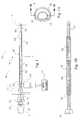
- FIG. 1is a side elevational view of the needle and stylet, with the needle inserted into the nerve sheath;
- FIG. 1Ais an end-on elevational view from the distal end of the needle structure, showing a detail of the tip of the needle, the tip of the stylet the and non-conductive needle material covering the region of the needle between the proximal ends;
- FIG. 1Bis a side elevational view of the needle, with only a portion of the hub shown and the stylet removed, most of the needle being shown in section at section line 1 B— 1 B;
- FIG. 1Cis a detail of the needle tip
- FIG. 1Dis a side elevational view of the inner stylet
- FIG. 2is a side elevational view of the catheter
- FIG. 3is an enlarged version of FIG. 2, except that the catheter sheath is partially cut away to better show the structure of the helical wire, only portions of which are shown;
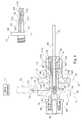
- FIG. 4is a side elevational view of the multipurpose connector in section, with the proximal end of the catheter inserted therein but not yet rigidly held in place;
- FIG. 5is a perspective view of the metal washer, multipurpose connector wires and sealing assembly of the multipurpose connector.
- FIG. 6is a side elevational view of the metal washer, multipurpose connector wires and sealing assembly of the multipurpose connector.
- FIG. 1there is shown relevant portions of a human body 10 containing a nerve 12 located subcutaneous to adjacent neck portion 14 .
- a needle assembly 16has been inserted into a specific point in the neck 14 of the human body 10 for the purpose of locating the nerve 12 .
- the needle assembly 16comprises a needle 18 and a central stylet 20 which extend coaxially of one another.
- the needle 18is a metal needle which is joined at its rear end to a hub 22 of a plastic material.
- the needle 18is hollow and projects about 95 mm forwardly of the hub 22 .
- the needle 18has three portions along its length.
- the major portion of the needleis the central portion 24 thereof.
- This central portion 24 of the needleis wrapped on the outside surface thereof in an insulating coating 26 which will not conduct electricity.
- This coating 26is shown in FIG. 1 as being divided into sections of alternating color 28 and 30 . Each of these sections is of a known, specific, length. Such colored sectioning enables the user to determine the extent of penetration of the tip 32 of the needle 18 .
- the remaining two portions of the needle 18are the distal end 34 and the proximal end 36 .
- the needle 18extends within the hub 22 where it is secured, such as by molding the hub around the needle.
- the proximal end 36 of the needle 18is exposed such that electrical contact with the remainder of the needle may be achieved by contact with the exposed proximal end 36 .
- the bore through the needle 38opens into an axially-aligned bore 40 through the hub 22 of the same diameter as the needle bore 38 .
- the rear end of the bore 42is enlarged and tapered to provide a female Luer opening 44 for use in receiving the stylet 20 and stylet hub 21 .
- the hub 22is provided with an axially-extending slot or keyway 25 formed in the outer surface of the hub, on that side of the hub to which the tip 32 of the needle 18 is inclined.
- the forward 5 mm or so 31 of the needle 18is bent downwardly at an angle of about 20°, the distal end 34 of the needle being cut such that it makes an angle ⁇ of about 10° with the axis of the major part of the needle.
- This inclined end of the needleprovides it with a tip 32 constituting a sharp point that readily pierces body tissue.
- the distal end 34 of the needleis not covered by any electrically insulating material and is in electrical contact, by way of the covered central portion 24 , with the proximal end 36 of the needle.
- the insulating coating 26prevents the flow of electricity radially out of the central portion 24 of the needle, but allows the flow of electricity axially along the length of the needle 18 .
- the inner stylet 20is formed of a solid metal needle.
- the distal tip 45 of the stylet 20is cut to have the same sharp tip angle ⁇ as the tip 32 of the needle.
- a stylet hub 21 of plastic materialJoined to the proximal end of the stylet 20 is a stylet hub 21 of plastic material.
- the stylet 20is smaller in diameter than the outer needle 18 and is straight along its entire length.
- the connector 46 of the stylet hub 21 which grasps the stylet 20is of generally cylindrical shape.
- the forward end of the connector 46has a Luer taper 48 that is dimensioned to fit within the Luer-tapered opening 44 in the needle hub 22 .
- a short peg or key 50 of rectangular sectionis provided along the lower side of the stylet hub 21 , as viewed in FIG. 1 .
- the peg 50extends axially of the stylet hub 21 , being spaced outwardly by a small gap from its Luer-tapered section 48 .
- the peg 50is aligned with respect to the stylet hub 21 and stylet 20 such that, when the peg is engaged in the slot 25 of the needle hub 22 , the plane of the inclined tip 45 of the stylet 20 lies in the same plane as the inclined tip 34 of the needle.
- the combined sharp tips of the needle and styletreadily pierces body tissue while the stylet, occupying the center bore 38 of the needle, prevents any tissue from entering the needle bore 38 .
- an electrical connector 52which may be in the form of an alligator clip which conveys electrical impulses from an anaesthetic nerve stimulator 17 to the proximal end of the needle 36 .
- FIG. 1Ais an end on view of the tip of the needle assembly 16 , showing the inclined tip of the needle 32 the inclined tip 45 of the stylet 20 . Also shown is the insulating coating 26 .
- FIG. 1Bis a detail of the needle 18 of the needle assembly, with the stylet 20 removed and only showing a small portion of the hub 22 .
- the needle 18 of FIG. 1has been sectioned along section line 1 B of FIG. 1 A.
- FIG. 1Bshows the relationship of the insulating coating 26 (of exaggerated thickness) to the various portions of the needle 18 .
- the catheter assembly 54is of a diameter which allows the assembly to be inserted through the needle assembly 16 and into the body of the patient.
- the catheter assembly 54comprising a sheath 56 formed from a thermoplastic or similar material.
- a helical coil of wire 58best shown in FIG. 3, possesses three portions. A proximal portion 60 , a central portion 62 and a distal portion 64 . For its entire length, the helical wire 58 defines a central bore 66 through which a liquid may freely pass.
- the central portion 60 of the helical wire 58is completely covered by the catheter sheath 56 and constitutes the vast majority of the total length of the catheter assembly 54 .
- the proximal portion 60 of the helical wirehas no distinguishing features except that it is short relative to the central portion of the remainder of the catheter assembly 54 and is not covered by the catheter sheath.
- the proximal portion of helical wireis left exposed so that it, and therefore the entire wire helix 58 , may be electrically contacted, as will be discussed relative to other structures.
- the distal portion 64 of the helical wirewhich is also short relative to the remainder of the catheter assembly 54 and not covered by the catheter sheath 56 , has several features associated therewith.
- the helical wire 58exits the catheter sheath 56 at the distal end thereof, the helix maintains the tightly wound nature of the proximal 60 and central 62 portions of the wire.
- This tight helixcontinues for a short distance along the distal portion before the helix opens up considerably at an open helix portion 68 .
- the open helix portion 68continues for several revolutions of the helix, before the structure returns for the tightly wound end 70 of the distal portion 64 .
- Attached to the distal end of the tightly wound end portionis a wire helix tip 72 which is a piece of rounded metal.
- a catheter adapter 74Accessing the central bore 66 of the catheter assembly 54 would be nearly impossible given the diameter of this structure. This being the case, a catheter adapter 74 is needed to provide access to the central bore 66 of the catheter assembly 54 for various delivery vehicles, e.g. a syringe, for the controlled delivery of fluid through the catheter.
- various delivery vehiclese.g. a syringe
- the main constituents of the catheter adapterare the rear body 76 , the front body 78 and the holding hub 80 .
- the rear body 78has a central flange 82 . From the rear face 84 of the central flange 82 extends a connection cylinder 86 having a threaded outer surface 88 and a hollow central bore 90 . The function of this cylinder is to facilitate luer attachment of apparatus for controlled delivery of fluid to the catheter assembly 54 .
- the end cap 92 provided with the catheter adapter 74is primarily for sterility purposes, and is simply removed after the catheter adapter 74 is attached to the catheter assembly 54 .
- the central flangehas, at its center, a bore 93 passing completely therethrough such that the rear face 84 and front face 94 are in fluid communication.
- an operating cylinder 96From the front face 94 of the central flange 82 extends an operating cylinder 96 . Where the operating cylinder 96 is connected to the front face 94 of the central flange 82 , it is of a certain diameter 95 . Along the length of the operating cylinder, the diameter of the operating cylinder is reduced by a taper 98 . The remainder of the operating cylinder is of this reduced diameter 99 to the distal end 100 of the operating cylinder.
- the operating cylinder 96has a central bore 102 which extends along the entire length thereof. Axial slots 104 extend from the distal end 100 of the operating cylinder, nearly the length thereof, i.e.
- the slot ends 106extend nearly to the juncture of the operating cylinder 96 and the front face 94 of the central flange 82 .
- Contained in and extending most of the length of the central bore 102 of the operating cylinder 96is an elongated rubber gasket 105 .
- the front body 78 of the catheter adapterhas a structure similar in geometry to the central flange 82 the rear body 76 , this structure is called the rear flange 110 .
- the rear flange 110has extending from the front face 112 thereof a front cylinder 114 .
- the front cylinder 114has an essentially constant outside diameter extending from the front face 112 of the rear flange 110 to the distal end 116 of the front cylinder.
- a central bore 118is provided in the front cylinder 114 , extending the entire length thereof. This central bore 118 has several different diameter changes along its length.
- the diameter of the boreis slightly larger that the diameter 95 of the operating cylinder 96 where it is connected to the front face 94 of the central flange 82 .
- the inside diameteris reduced by a taper 123 which is a mirror image of taper 98 on the operating cylinder.
- the holding hub 80is a generally tubular body provided with a cylindrical recess 126 formed in the rear face 128 thereof.
- the distal end 100 of the operating cylinder 96is matingly engageable with the cylindrical recess 126 of the holding hub 80 and is rigidly attached thereto.
- the diameter of the central bore 120 of the front body 78is, from the front face thereof 94 to a depth less than the length of the holding hub, slightly greater than the diameter of the holding hub.
- the rigid connection between the holding hub 80 and the distal end 100 of the operating cylinderholds these two structures in slidable relationship with the front body 78 .
- the catheter adapter 74is initially in the configuration shown in FIG. 4 .
- the proximal end 57 of the catheter assembly 54may be freely inserted and withdrawn from the catheter adapter.
- the proximal end 57 of the catheter assembly 54may be held in place by sliding the front body 78 toward the rear body 76 of the catheter adapter.
- the taper 98 of the operating cylinder 96will be compressed by the taper 123 of the interior of the front body.
- the slots 104 in the operating cylinder 96allow this compression to occur.
- the compression of the operating cylinderresults in the compression of the elongated rubber gasket 105 .
- This compression of the elongated rubber gasket 105results in the rubber gasket fictionally engaging the proximal end 57 of the catheter assembly 54 such that the catheter may not be easily removed from the catheter adapter.
- the metal washer 130is disposed about the operating cylinder 96 adjacent the front face 94 of the central flange 82 , and is held in place by nut 132 .
- the metal washer 130is provided with a tab portion 134 which extends above the flange portions 82 and 110 . This allows electrical contact to be made to the washer by way of the same electrical connector 52 as was used previously to conduct electricity into the needle assembly 16 from an anaesthetic nerve stimulator 17 .
- a pair of wires 138are attached to the metal washer 130 and extend from the metal washer to the internal bore 140 of the elongated rubber gasket 105 .
- the above described apparatusmay be used in numerous different medical procedures.
- the following described medical procedureis one type which utilizes the features embodied in the above described apparatus.
- the methodis drawn to the correct placement of the catheter assembly 54 and, more particularly, the distal portion 64 thereof. Once the distal portion 64 of the catheter assembly 54 is determined to be in the correct position, a continuous interscalene nerve block may be administered.
- the patientis positioned in the dorsal recumbent position with the head slightly in extension and turned somewhat to the opposite side.
- An assistantapplies light traction on the arm with the elbow flexed.
- the interscalene grooveis easily palpated in this position by the following procedure: First, the posterior edge of the clavicular head of the sternocleidomastoid muscle is located; then the palpating fingers are placed postero-lateral to this muscle to identify the interscalene groove.
- the external jugular veinalmost always lies directly superficial to the interscalene groove and provides a useful additional landmark. Needle entry should be anterior or posterior to the vein.
- Another constant findingis that the interscalene groove is approximately 3 cm lateral to the most prominent portion of the belly of the sternocleidomastoid muscle at the level of the cricoid cartilage.
- the needle assembly 16is inserted into the interscalene groove at the level of the cricoid (C 6 level) and the needle is directed perpendicular to the skin in all the planes.
- the needle assembly 16enters the skin at a point approximately halfway between the mastoid and the clavicle, posterior to the posterior border of the clavicular head of the sternocleidomastoid muscle.
- the point of needle entryis just caudal to the accessory nerve and just posterior to the anterior border of the posterior triangle of the neck.
- the accessory nervecan usually be identified by stimulating percutaneously with the electrical connector 52 of the nerve stimulator 17 since the nerve runs superficial to the fascial carpet of the posterior triangle of the neck, approximately midway between the clavicle and the mastoid.
- the needle assembly 16is directed caudal and parallel to the vertebrae aiming for the interscalene groove with the bevel of the needle assembly 16 directed laterally (outwards) to avoid possible central (epidural) placement of the catheter.
- All these nervesshould be avoided by redirection and/or reinsertion of the needle assembly 16 as stimulation of these nerves can provide false indications of correct needle placement that will most certainly lead to block failure or phrenic nerve paralysis if local anesthetic agent is injected at this stage.
- the central stylet 20is removed from the needle 18 and the catheter assembly 54 is fed through the needle 18 to a point just past the tip of the needle 32 .
- Such a placement of the wire helix tip 72is far enough so that the metal helical wire 58 does not make contact with the needle, i.e. the needle tip 32 is in contact with the catheter sheath 56 which will not conduct (disperse) electricity.
- the catheter adapter 74can be attached to the proximal end 60 of the catheter assembly 54 at this point, if it has not been attached previously.
- the electrical connector 52 of the nerve stimulator 17is then clipped to the tab portion 134 of the metal washer 130 provided on the catheter adapter 74 .
- the output of the nerve stimulator 17can be turned down (typically to approximately 0.5-1.0 mA) as the muscle twitching will increase because all the current is now concentrated in the unsheathed helix tip 72 of the catheter assembly 54 . Muscle contractions with a nerve stimulator 17 output of approximately 0.5 mA provides additional proof of proper placement into the sheath.
- Indwelling interscalene cathetersare notorious for falling out or dislodging.
- the same needle 16 used to place the catheteris inserted subcutaneously from just above the suprasternal notch and directed superolaterally, avoiding vascular structures, towards the point of entry of the catheter.
- the needle assembly 16is advanced to exit through the same orifice in the skin as the catheter 54 and just next to the catheter.
- the proximal end of the catheter 60is fed from the tip of the needle 32 through the needle 18 and the needle is removed so that the catheter 54 is tunneled subcutaneously.
- anaestheticmay be administered to effectuate a nerve block:
- Ropivacaine10 mg/mL (1%). Inject 20 mL as a bolus and then infuse with syringe driver a diluted concentration (5 mg/mL or 0.5%) at 10-20 mL/hour.
- Bupivacaine 5 mg/mL (0.5%)Inject 20 mL as a bolus and then infuse a diluted concentration (2.5 mg/mL or 0.25%) at 10-20 mL/hour.
- Ropivacaine2 mg/mL (0.2%). Inject 10-20 mL as a bolus and then infuse the same concentration at 1-10 mL/hour. Continually adjust (titrate) the infusion rate to achieve the desired effect.
Landscapes
- Health & Medical Sciences (AREA)
- Surgery (AREA)
- Life Sciences & Earth Sciences (AREA)
- Molecular Biology (AREA)
- General Health & Medical Sciences (AREA)
- Pathology (AREA)
- Engineering & Computer Science (AREA)
- Biomedical Technology (AREA)
- Heart & Thoracic Surgery (AREA)
- Medical Informatics (AREA)
- Anesthesiology (AREA)
- Animal Behavior & Ethology (AREA)
- Nuclear Medicine, Radiotherapy & Molecular Imaging (AREA)
- Public Health (AREA)
- Veterinary Medicine (AREA)
- Infusion, Injection, And Reservoir Apparatuses (AREA)
- Pharmaceuticals Containing Other Organic And Inorganic Compounds (AREA)
- Electrotherapy Devices (AREA)
- Media Introduction/Drainage Providing Device (AREA)
- Medicinal Preparation (AREA)
- Solid-Sorbent Or Filter-Aiding Compositions (AREA)
- Acyclic And Carbocyclic Compounds In Medicinal Compositions (AREA)
Abstract
Description
Claims (1)
Priority Applications (14)
| Application Number | Priority Date | Filing Date | Title |
|---|---|---|---|
| US09/524,467US6456874B1 (en) | 2000-03-13 | 2000-03-13 | Instrument for delivery of anaesthetic drug |
| CA2403197ACA2403197C (en) | 2000-03-13 | 2001-03-12 | Instrument and method for delivery of anaesthetic drug |
| JP2001566721AJP4812218B2 (en) | 2000-03-13 | 2001-03-12 | Apparatus and method for anesthetic delivery |
| DE60129543TDE60129543T2 (en) | 2000-03-13 | 2001-03-12 | INSTRUMENT FOR ADMINISTRATIVE ANESTHETICS |
| MXPA02008905AMXPA02008905A (en) | 2000-03-13 | 2001-03-12 | Instrument and method for delivery of anaesthetic drug. |
| EP01918529AEP1276535B1 (en) | 2000-03-13 | 2001-03-12 | Instrument for delivery of anaesthetic drug |
| PCT/US2001/007718WO2001068159A2 (en) | 2000-03-13 | 2001-03-12 | Instrument and method for delivery of anaesthetic drug |
| AU2001245595AAU2001245595A1 (en) | 2000-03-13 | 2001-03-12 | Instrument and method for delivery of anaesthetic drug |
| AT01918529TATE367844T1 (en) | 2000-03-13 | 2001-03-12 | INSTRUMENT FOR ADMINISTRATION OF ANESTHETICS |
| US10/188,605US6973346B2 (en) | 2000-03-13 | 2002-07-02 | Instrument and method for delivery of anaesthetic drug |
| ZA200207366AZA200207366B (en) | 2000-03-13 | 2002-09-13 | Instrument and method for delivery of anaesthetic drug. |
| US10/441,867US7386341B2 (en) | 2000-03-13 | 2003-05-20 | Instrument and method for delivery of anaesthetic drugs |
| US11/074,515US8611993B2 (en) | 2000-03-13 | 2005-03-08 | Pre-loaded lockable stimulating catheter for delivery of anaesthetic drugs |
| US12/101,777US7715925B2 (en) | 2000-03-13 | 2008-04-11 | Instrument and method for delivery of anaesthetic drugs |
Applications Claiming Priority (1)
| Application Number | Priority Date | Filing Date | Title |
|---|---|---|---|
| US09/524,467US6456874B1 (en) | 2000-03-13 | 2000-03-13 | Instrument for delivery of anaesthetic drug |
Related Child Applications (1)
| Application Number | Title | Priority Date | Filing Date |
|---|---|---|---|
| US10/188,605DivisionUS6973346B2 (en) | 2000-03-13 | 2002-07-02 | Instrument and method for delivery of anaesthetic drug |
Publications (1)
| Publication Number | Publication Date |
|---|---|
| US6456874B1true US6456874B1 (en) | 2002-09-24 |
Family
ID=24089323
Family Applications (2)
| Application Number | Title | Priority Date | Filing Date |
|---|---|---|---|
| US09/524,467Expired - LifetimeUS6456874B1 (en) | 2000-03-13 | 2000-03-13 | Instrument for delivery of anaesthetic drug |
| US10/188,605Expired - LifetimeUS6973346B2 (en) | 2000-03-13 | 2002-07-02 | Instrument and method for delivery of anaesthetic drug |
Family Applications After (1)
| Application Number | Title | Priority Date | Filing Date |
|---|---|---|---|
| US10/188,605Expired - LifetimeUS6973346B2 (en) | 2000-03-13 | 2002-07-02 | Instrument and method for delivery of anaesthetic drug |
Country Status (10)
| Country | Link |
|---|---|
| US (2) | US6456874B1 (en) |
| EP (1) | EP1276535B1 (en) |
| JP (1) | JP4812218B2 (en) |
| AT (1) | ATE367844T1 (en) |
| AU (1) | AU2001245595A1 (en) |
| CA (1) | CA2403197C (en) |
| DE (1) | DE60129543T2 (en) |
| MX (1) | MXPA02008905A (en) |
| WO (1) | WO2001068159A2 (en) |
| ZA (1) | ZA200207366B (en) |
Cited By (60)
| Publication number | Priority date | Publication date | Assignee | Title |
|---|---|---|---|---|
| US20020198557A1 (en)* | 2001-05-08 | 2002-12-26 | Helmut Freigang | Puncture cannula |
| US20040210295A1 (en)* | 2000-03-24 | 2004-10-21 | Stephen Brushey | Anesthesia conduction catheter for delivery of electrical stimulus |
| US20050043709A1 (en)* | 2002-10-10 | 2005-02-24 | Brimhall Greg L. | System and method of delivering local anesthesia |
| WO2004082738A3 (en)* | 2003-03-13 | 2005-09-01 | Medtronic Transvascular Inc | Optically guided penetration catheters and their methods of use |
| US20060217655A1 (en)* | 2000-03-13 | 2006-09-28 | Vitullo Jeffrey M | Pre-loaded lockable stimulating catheter for delivery of anaesthetic drugs |
| US20080058757A1 (en)* | 2006-04-28 | 2008-03-06 | Pajunk Gmbh & Co. Kg Besitzverwaltung | Catheter Set for Epidural or Peripheral Nerve Blockade |
| US20080202626A1 (en)* | 2007-02-23 | 2008-08-28 | John Arthur Morin | Filling needle |
| US20080300530A1 (en)* | 2007-06-04 | 2008-12-04 | I-Flow Corporation | Stimulating catheter |
| US20090105693A1 (en)* | 2007-10-22 | 2009-04-23 | B. Braun Medical Inc. | Catheter switch and method of using a catheter switch in administering a nerve or plexus block |
| US20100314796A1 (en)* | 2006-08-03 | 2010-12-16 | Becton, Dickinson And Company | Syringe and Removable Needle Assembly Having Binary Attachment Features |
| US7987001B2 (en) | 2007-01-25 | 2011-07-26 | Warsaw Orthopedic, Inc. | Surgical navigational and neuromonitoring instrument |
| WO2012159000A2 (en) | 2011-05-18 | 2012-11-22 | Solodex Llc | Continuous anesthesia nerve conduction apparatus, system and method |
| US8374673B2 (en) | 2007-01-25 | 2013-02-12 | Warsaw Orthopedic, Inc. | Integrated surgical navigational and neuromonitoring system having automated surgical assistance and control |
| US8641677B2 (en) | 2010-01-21 | 2014-02-04 | James T. Rawls | Low-profile intravenous catheter device |
| WO2014074237A1 (en) | 2012-11-09 | 2014-05-15 | Solodex Llc | Continuous anesthesia nerve conduction apparatus, system and method thereof |
| US8801693B2 (en) | 2010-10-29 | 2014-08-12 | C. R. Bard, Inc. | Bioimpedance-assisted placement of a medical device |
| US20140316328A1 (en)* | 2011-05-18 | 2014-10-23 | Solodex Llc | Continuous anesthesia nerve conduction apparatus, system and method thereof |
| US9265443B2 (en) | 2006-10-23 | 2016-02-23 | Bard Access Systems, Inc. | Method of locating the tip of a central venous catheter |
| US9308022B2 (en) | 2012-12-10 | 2016-04-12 | Nevro Corporation | Lead insertion devices and associated systems and methods |
| US9339206B2 (en) | 2009-06-12 | 2016-05-17 | Bard Access Systems, Inc. | Adaptor for endovascular electrocardiography |
| US9345422B2 (en) | 2006-10-23 | 2016-05-24 | Bard Acess Systems, Inc. | Method of locating the tip of a central venous catheter |
| US9445734B2 (en) | 2009-06-12 | 2016-09-20 | Bard Access Systems, Inc. | Devices and methods for endovascular electrography |
| US9445743B2 (en) | 2003-02-21 | 2016-09-20 | 3Dt Holdings, Llc | Methods for generating luminal organ profiles using impedance |
| US9456766B2 (en) | 2007-11-26 | 2016-10-04 | C. R. Bard, Inc. | Apparatus for use with needle insertion guidance system |
| US9492097B2 (en) | 2007-11-26 | 2016-11-15 | C. R. Bard, Inc. | Needle length determination and calibration for insertion guidance system |
| US9521961B2 (en) | 2007-11-26 | 2016-12-20 | C. R. Bard, Inc. | Systems and methods for guiding a medical instrument |
| US9526440B2 (en) | 2007-11-26 | 2016-12-27 | C.R. Bard, Inc. | System for placement of a catheter including a signal-generating stylet |
| US9532724B2 (en) | 2009-06-12 | 2017-01-03 | Bard Access Systems, Inc. | Apparatus and method for catheter navigation using endovascular energy mapping |
| US9549685B2 (en) | 2007-11-26 | 2017-01-24 | C. R. Bard, Inc. | Apparatus and display methods relating to intravascular placement of a catheter |
| US9554716B2 (en) | 2007-11-26 | 2017-01-31 | C. R. Bard, Inc. | Insertion guidance system for needles and medical components |
| US9636031B2 (en) | 2007-11-26 | 2017-05-02 | C.R. Bard, Inc. | Stylets for use with apparatus for intravascular placement of a catheter |
| US9649048B2 (en) | 2007-11-26 | 2017-05-16 | C. R. Bard, Inc. | Systems and methods for breaching a sterile field for intravascular placement of a catheter |
| US9681823B2 (en) | 2007-11-26 | 2017-06-20 | C. R. Bard, Inc. | Integrated system for intravascular placement of a catheter |
| US9839372B2 (en) | 2014-02-06 | 2017-12-12 | C. R. Bard, Inc. | Systems and methods for guidance and placement of an intravascular device |
| WO2017211601A1 (en)* | 2016-06-06 | 2017-12-14 | Pajunk GmbH Medizintechnologie | Monopolar cannula |
| US9901714B2 (en) | 2008-08-22 | 2018-02-27 | C. R. Bard, Inc. | Catheter assembly including ECG sensor and magnetic assemblies |
| US9907513B2 (en) | 2008-10-07 | 2018-03-06 | Bard Access Systems, Inc. | Percutaneous magnetic gastrostomy |
| US10004875B2 (en) | 2005-08-24 | 2018-06-26 | C. R. Bard, Inc. | Stylet apparatuses and methods of manufacture |
| US10046139B2 (en) | 2010-08-20 | 2018-08-14 | C. R. Bard, Inc. | Reconfirmation of ECG-assisted catheter tip placement |
| US10159531B2 (en) | 2012-04-05 | 2018-12-25 | C. R. Bard, Inc. | Apparatus and methods relating to intravascular positioning of distal end of catheter |
| US10172538B2 (en) | 2003-02-21 | 2019-01-08 | 3Dt Holdings, Llc | Body lumen junction localization |
| US10231643B2 (en) | 2009-06-12 | 2019-03-19 | Bard Access Systems, Inc. | Apparatus and method for catheter navigation and tip location |
| US10349890B2 (en) | 2015-06-26 | 2019-07-16 | C. R. Bard, Inc. | Connector interface for ECG-based catheter positioning system |
| US10413211B2 (en) | 2003-02-21 | 2019-09-17 | 3Dt Holdings, Llc | Systems, devices, and methods for mapping organ profiles |
| US10449330B2 (en) | 2007-11-26 | 2019-10-22 | C. R. Bard, Inc. | Magnetic element-equipped needle assemblies |
| US10524691B2 (en) | 2007-11-26 | 2020-01-07 | C. R. Bard, Inc. | Needle assembly including an aligned magnetic element |
| US10568614B2 (en) | 2010-04-29 | 2020-02-25 | Cook Medical Technologies Llc | Systems and methods for facilitating closure of bodily openings |
| US10568628B2 (en) | 2017-05-23 | 2020-02-25 | Muffin Incorporated | Closing device for tissue openings |
| US10751509B2 (en) | 2007-11-26 | 2020-08-25 | C. R. Bard, Inc. | Iconic representations for guidance of an indwelling medical device |
| US10973584B2 (en) | 2015-01-19 | 2021-04-13 | Bard Access Systems, Inc. | Device and method for vascular access |
| US10980999B2 (en) | 2017-03-09 | 2021-04-20 | Nevro Corp. | Paddle leads and delivery tools, and associated systems and methods |
| US10992079B2 (en) | 2018-10-16 | 2021-04-27 | Bard Access Systems, Inc. | Safety-equipped connection systems and methods thereof for establishing electrical connections |
| US11000205B2 (en) | 2012-04-05 | 2021-05-11 | Bard Access Systems, Inc. | Devices and systems for navigation and positioning a central venous catheter within a patient |
| US11000207B2 (en) | 2016-01-29 | 2021-05-11 | C. R. Bard, Inc. | Multiple coil system for tracking a medical device |
| US11420045B2 (en) | 2018-03-29 | 2022-08-23 | Nevro Corp. | Leads having sidewall openings, and associated systems and methods |
| US11471595B2 (en)* | 2017-05-04 | 2022-10-18 | Milestone Scientific, Inc. | Method and apparatus for performing a peripheral nerve block |
| US11759268B2 (en) | 2012-04-05 | 2023-09-19 | C. R. Bard, Inc. | Apparatus and methods relating to intravascular positioning of distal end of catheter |
| US11793545B2 (en) | 2019-04-08 | 2023-10-24 | Daniel E. Matthews | Adductor canal block introducer |
| US12029539B2 (en) | 2003-02-21 | 2024-07-09 | 3Dt Holdings, Llc | Systems, devices, and methods for mapping organ profiles |
| US12096957B2 (en) | 2020-04-24 | 2024-09-24 | Milestone Scientific, Inc. | Device and method for needle/catheter location utilizing correlation analysis |
Families Citing this family (32)
| Publication number | Priority date | Publication date | Assignee | Title |
|---|---|---|---|---|
| US7386341B2 (en)* | 2000-03-13 | 2008-06-10 | Arrow International, Inc. | Instrument and method for delivery of anaesthetic drugs |
| FR2835436B1 (en)* | 2002-02-07 | 2004-11-26 | Georges Boussignac | INSTRUMENTATION FOR ANALGESIA, ESPECIALLY PERIDURAL |
| FR2847169B1 (en)* | 2002-11-20 | 2005-02-18 | Vygon | DEVICE FOR LOCOREGIONAL ANESTHESIA AND METHOD FOR MANUFACTURING THE CANNULA OF THE DEVICE |
| DE202005000544U1 (en)* | 2005-01-13 | 2006-05-24 | Mantsch, Christian | Medical electrode system |
| US20080058702A1 (en)* | 2005-12-12 | 2008-03-06 | Cook Critical Care Incorporated | Continuous nerve block assembly |
| US8136532B2 (en)* | 2006-08-30 | 2012-03-20 | Med-El Elektromedizinische Geraete Gmbh | System, apparatus, and method for facilitating interface with laryngeal structures |
| JP5105813B2 (en)* | 2006-09-28 | 2012-12-26 | 株式会社八光 | Epidural puncture needle |
| KR100741171B1 (en) | 2006-11-30 | 2007-07-20 | 강신범 | Epidural Anesthesia Needle and Epidural Anesthesia Device |
| US7927281B2 (en)* | 2007-10-08 | 2011-04-19 | Jay Wheeler | Automated needle pen drug delivery system |
| US8478382B2 (en) | 2008-02-11 | 2013-07-02 | C. R. Bard, Inc. | Systems and methods for positioning a catheter |
| WO2011044421A1 (en) | 2009-10-08 | 2011-04-14 | C. R. Bard, Inc. | Spacers for use with an ultrasound probe |
| KR20110033892A (en)* | 2009-12-23 | 2011-04-01 | 신현순 | Catheter and catheter assembly |
| CN103228219B (en) | 2010-08-09 | 2016-04-27 | C·R·巴德股份有限公司 | Support and Covering Structures for Ultrasound Probe Heads |
| JP5775584B2 (en)* | 2010-09-10 | 2015-09-09 | セウン メディカル カンパニー リミテッド | Catheter set with guide wire |
| US20120197214A1 (en)* | 2011-02-02 | 2012-08-02 | Mark David Manley | Peripheral nerve blockade device |
| JP5847453B2 (en)* | 2011-06-23 | 2016-01-20 | 株式会社トップ | Catheter connector |
| JP5847452B2 (en)* | 2011-06-23 | 2016-01-20 | 株式会社トップ | Catheter connector |
| USD699359S1 (en) | 2011-08-09 | 2014-02-11 | C. R. Bard, Inc. | Ultrasound probe head |
| USD724745S1 (en) | 2011-08-09 | 2015-03-17 | C. R. Bard, Inc. | Cap for an ultrasound probe |
| US20130046153A1 (en) | 2011-08-16 | 2013-02-21 | Elwha LLC, a limited liability company of the State of Delaware | Systematic distillation of status data relating to regimen compliance |
| US9211107B2 (en) | 2011-11-07 | 2015-12-15 | C. R. Bard, Inc. | Ruggedized ultrasound hydrogel insert |
| US9439598B2 (en) | 2012-04-12 | 2016-09-13 | NeuroMedic, Inc. | Mapping and ablation of nerves within arteries and tissues |
| EP2861153A4 (en) | 2012-06-15 | 2016-10-19 | Bard Inc C R | Apparatus and methods for detection of a removable cap on an ultrasound probe |
| US9440047B1 (en) | 2013-03-14 | 2016-09-13 | Angiodynamics, Inc. | Systems and methods for catheter tip placement using ECG |
| US9445746B1 (en) | 2013-03-14 | 2016-09-20 | Angio Dynamics, Inc. | Systems and methods for catheter tip placement using ECG |
| US10188831B2 (en) | 2013-03-14 | 2019-01-29 | Angiodynamics, Inc. | Systems and methods for catheter tip placement using ECG |
| US9409014B2 (en) | 2013-06-12 | 2016-08-09 | Med-El Elektromedizinische Geraete Gmbh | Method for modifying larynx position by trans-positioning muscle and electrode stimulation |
| US9108054B2 (en) | 2013-06-12 | 2015-08-18 | Med-El Elektromedizinische Geraete Gmbh | Method for modifying larynx position by trans-positioning muscle and electrode stimulation |
| US20150282734A1 (en) | 2014-04-08 | 2015-10-08 | Timothy Schweikert | Medical device placement system and a method for its use |
| US11318310B1 (en) | 2015-10-26 | 2022-05-03 | Nevro Corp. | Neuromodulation for altering autonomic functions, and associated systems and methods |
| US11590352B2 (en) | 2019-01-29 | 2023-02-28 | Nevro Corp. | Ramped therapeutic signals for modulating inhibitory interneurons, and associated systems and methods |
| CN112773478B (en)* | 2021-02-03 | 2025-09-09 | 中南大学湘雅二医院 | Continuous nerve block catheter delivery system and method |
Citations (11)
| Publication number | Priority date | Publication date | Assignee | Title |
|---|---|---|---|---|
| US4518383A (en) | 1982-08-06 | 1985-05-21 | Evans John M | Instrument and method for epidural and spinal anaesthesia |
| US4644960A (en) | 1985-09-23 | 1987-02-24 | Arrow International, Inc. | Device for making electrical connection to an electrolyte, and system employing same |
| US4824433A (en)* | 1982-08-06 | 1989-04-25 | Sterimed Gesellschaft Fur Medizinischen Bedarf Mbh | Puncturing and catheterizing device for the human or animal body |
| US5007902A (en)* | 1988-03-09 | 1991-04-16 | B. Braun Melsungen Ag | Catheter set for plexus anesthesia |
| US5135525A (en) | 1989-06-06 | 1992-08-04 | B. Braun Melsungen Ag | Catheter set for continuous spinal anaesthesia |
| US5304141A (en) | 1989-12-11 | 1994-04-19 | Brigham And Women's Hospital | Method and apparatus for inducing anesthesia |
| US5423877A (en) | 1992-05-04 | 1995-06-13 | David C. Mackey | Method and device for acute pain management by simultaneous spinal cord electrical stimulation and drug infusion |
| US5830151A (en)* | 1995-04-10 | 1998-11-03 | Innovative Design Associates | Apparatus for locating and anesthetizing peripheral nerves a method therefor |
| WO1999004705A1 (en) | 1997-07-25 | 1999-02-04 | Tsui Ban C H | Devices, systems and methods for determining proper placement of epidural catheters |
| US5976110A (en) | 1998-01-14 | 1999-11-02 | Duke University | Catheter system for administration of continuous peripheral nerve anesthetic |
| US6298256B1 (en) | 1999-09-10 | 2001-10-02 | Frank-Egbert Meyer | Device and method for the location and catheterization of the surroundings of a nerve |
Family Cites Families (17)
| Publication number | Priority date | Publication date | Assignee | Title |
|---|---|---|---|---|
| US3682162A (en) | 1968-12-13 | 1972-08-08 | Wellcome Found | Combined electrode and hypodermic syringe needle |
| DE3102142C2 (en)* | 1981-01-23 | 1989-05-18 | B. Braun Melsungen Ag, 3508 Melsungen | Catheter connector |
| US4515168A (en) | 1983-07-22 | 1985-05-07 | Chester Martin H | Clamp-on nerve stimulator and locator |
| US4801293A (en) | 1985-10-09 | 1989-01-31 | Anthony Jackson | Apparatus and method for detecting probe penetration of human epidural space and injecting a therapeutic substance thereinto |
| US4842592A (en)* | 1987-05-06 | 1989-06-27 | Teleflex Incorporated | Connector assembly |
| US4973312A (en) | 1989-05-26 | 1990-11-27 | Andrew Daniel E | Method and system for inserting spinal catheters |
| US5081990A (en) | 1990-05-11 | 1992-01-21 | New York University | Catheter for spinal epidural injection of drugs and measurement of evoked potentials |
| US5092344A (en) | 1990-11-19 | 1992-03-03 | Lee Tzium Shou | Remote indicator for stimulator |
| US5562722A (en)* | 1994-03-14 | 1996-10-08 | Medical Evaluation Devices & Instruments Corp. | Multiple electrode catheter |
| US5853373A (en) | 1996-08-05 | 1998-12-29 | Becton, Dickinson And Company | Bi-level charge pulse apparatus to facilitate nerve location during peripheral nerve block procedures |
| US5782505A (en)* | 1996-08-29 | 1998-07-21 | Becton, Dickinson And Company | Catheter adapter assembly |
| US5899891A (en) | 1996-09-05 | 1999-05-04 | Epimed International, Inc. | Catheter |
| AU6258498A (en)* | 1997-01-30 | 1998-08-25 | Mayo Foundation For Medical Education And Research | Peripheral nerve site anesthesia |
| US5902273A (en) | 1997-10-15 | 1999-05-11 | Yang; Ian Y. | Pressurizable epidural space identification syringe |
| US6104960A (en) | 1998-07-13 | 2000-08-15 | Medtronic, Inc. | System and method for providing medical electrical stimulation to a portion of the nervous system |
| US6259945B1 (en) | 1999-04-30 | 2001-07-10 | Uromed Corporation | Method and device for locating a nerve |
| CA2429572A1 (en) | 2000-11-24 | 2002-07-18 | Ckm Diagnostics, Inc. | Nerve stimulator output control needle with depth determination capability and method of use |
- 2000
- 2000-03-13USUS09/524,467patent/US6456874B1/ennot_activeExpired - Lifetime
- 2001
- 2001-03-12DEDE60129543Tpatent/DE60129543T2/ennot_activeExpired - Lifetime
- 2001-03-12JPJP2001566721Apatent/JP4812218B2/ennot_activeExpired - Fee Related
- 2001-03-12WOPCT/US2001/007718patent/WO2001068159A2/enactiveIP Right Grant
- 2001-03-12EPEP01918529Apatent/EP1276535B1/ennot_activeExpired - Lifetime
- 2001-03-12MXMXPA02008905Apatent/MXPA02008905A/ennot_activeApplication Discontinuation
- 2001-03-12AUAU2001245595Apatent/AU2001245595A1/ennot_activeAbandoned
- 2001-03-12CACA2403197Apatent/CA2403197C/ennot_activeExpired - Lifetime
- 2001-03-12ATAT01918529Tpatent/ATE367844T1/ennot_activeIP Right Cessation
- 2002
- 2002-07-02USUS10/188,605patent/US6973346B2/ennot_activeExpired - Lifetime
- 2002-09-13ZAZA200207366Apatent/ZA200207366B/enunknown
Patent Citations (11)
| Publication number | Priority date | Publication date | Assignee | Title |
|---|---|---|---|---|
| US4518383A (en) | 1982-08-06 | 1985-05-21 | Evans John M | Instrument and method for epidural and spinal anaesthesia |
| US4824433A (en)* | 1982-08-06 | 1989-04-25 | Sterimed Gesellschaft Fur Medizinischen Bedarf Mbh | Puncturing and catheterizing device for the human or animal body |
| US4644960A (en) | 1985-09-23 | 1987-02-24 | Arrow International, Inc. | Device for making electrical connection to an electrolyte, and system employing same |
| US5007902A (en)* | 1988-03-09 | 1991-04-16 | B. Braun Melsungen Ag | Catheter set for plexus anesthesia |
| US5135525A (en) | 1989-06-06 | 1992-08-04 | B. Braun Melsungen Ag | Catheter set for continuous spinal anaesthesia |
| US5304141A (en) | 1989-12-11 | 1994-04-19 | Brigham And Women's Hospital | Method and apparatus for inducing anesthesia |
| US5423877A (en) | 1992-05-04 | 1995-06-13 | David C. Mackey | Method and device for acute pain management by simultaneous spinal cord electrical stimulation and drug infusion |
| US5830151A (en)* | 1995-04-10 | 1998-11-03 | Innovative Design Associates | Apparatus for locating and anesthetizing peripheral nerves a method therefor |
| WO1999004705A1 (en) | 1997-07-25 | 1999-02-04 | Tsui Ban C H | Devices, systems and methods for determining proper placement of epidural catheters |
| US5976110A (en) | 1998-01-14 | 1999-11-02 | Duke University | Catheter system for administration of continuous peripheral nerve anesthetic |
| US6298256B1 (en) | 1999-09-10 | 2001-10-02 | Frank-Egbert Meyer | Device and method for the location and catheterization of the surroundings of a nerve |
Cited By (113)
| Publication number | Priority date | Publication date | Assignee | Title |
|---|---|---|---|---|
| US20060217655A1 (en)* | 2000-03-13 | 2006-09-28 | Vitullo Jeffrey M | Pre-loaded lockable stimulating catheter for delivery of anaesthetic drugs |
| US8611993B2 (en) | 2000-03-13 | 2013-12-17 | Arrow International, Inc. | Pre-loaded lockable stimulating catheter for delivery of anaesthetic drugs |
| US20100318095A1 (en)* | 2000-03-24 | 2010-12-16 | Safe Bt, Inc. | Anesthesia conduction catheter for delivery of electrical stimulus |
| US7805188B2 (en)* | 2000-03-24 | 2010-09-28 | Micor, Inc. | Anesthesia conduction catheter for delivery of electrical stimulus |
| US20040210295A1 (en)* | 2000-03-24 | 2004-10-21 | Stephen Brushey | Anesthesia conduction catheter for delivery of electrical stimulus |
| US20020198557A1 (en)* | 2001-05-08 | 2002-12-26 | Helmut Freigang | Puncture cannula |
| US6730083B2 (en)* | 2001-05-08 | 2004-05-04 | B. Braun Melsungen Ag | Puncture cannula |
| US20070250037A1 (en)* | 2002-10-10 | 2007-10-25 | Becton, Dickinson And Company | System and method of delivering local anesthesia |
| US7713256B2 (en) | 2002-10-10 | 2010-05-11 | Becton, Dickinson And Company | System and method of delivering local anesthesia |
| US7713257B2 (en) | 2002-10-10 | 2010-05-11 | Becton, Dickinson And Company | System and method of delivering local anesthesia |
| US20050043709A1 (en)* | 2002-10-10 | 2005-02-24 | Brimhall Greg L. | System and method of delivering local anesthesia |
| US10524685B2 (en) | 2003-02-21 | 2020-01-07 | 3Dt Holdings, Llc | Methods for generating luminal organ profiles using impedance |
| US11490829B2 (en) | 2003-02-21 | 2022-11-08 | 3Dt Holdings, Llc | Systems, devices, and methods for mapping organ profiles |
| US11510589B2 (en) | 2003-02-21 | 2022-11-29 | 3Dt Holdings, Llc | Body lumen junction localization |
| US9445743B2 (en) | 2003-02-21 | 2016-09-20 | 3Dt Holdings, Llc | Methods for generating luminal organ profiles using impedance |
| US12029539B2 (en) | 2003-02-21 | 2024-07-09 | 3Dt Holdings, Llc | Systems, devices, and methods for mapping organ profiles |
| US10172538B2 (en) | 2003-02-21 | 2019-01-08 | 3Dt Holdings, Llc | Body lumen junction localization |
| US10413211B2 (en) | 2003-02-21 | 2019-09-17 | 3Dt Holdings, Llc | Systems, devices, and methods for mapping organ profiles |
| US20060241342A1 (en)* | 2003-03-13 | 2006-10-26 | Medtronic Transvascular, Inc. | Optically guided penetration catheters and their methods of use |
| WO2004082738A3 (en)* | 2003-03-13 | 2005-09-01 | Medtronic Transvascular Inc | Optically guided penetration catheters and their methods of use |
| US11207496B2 (en) | 2005-08-24 | 2021-12-28 | C. R. Bard, Inc. | Stylet apparatuses and methods of manufacture |
| US10004875B2 (en) | 2005-08-24 | 2018-06-26 | C. R. Bard, Inc. | Stylet apparatuses and methods of manufacture |
| US20080058757A1 (en)* | 2006-04-28 | 2008-03-06 | Pajunk Gmbh & Co. Kg Besitzverwaltung | Catheter Set for Epidural or Peripheral Nerve Blockade |
| US7922958B2 (en) | 2006-08-03 | 2011-04-12 | Becton, Dickinson And Company | Method of making an elongate syringe barrel |
| US20100314796A1 (en)* | 2006-08-03 | 2010-12-16 | Becton, Dickinson And Company | Syringe and Removable Needle Assembly Having Binary Attachment Features |
| US9265443B2 (en) | 2006-10-23 | 2016-02-23 | Bard Access Systems, Inc. | Method of locating the tip of a central venous catheter |
| US9833169B2 (en) | 2006-10-23 | 2017-12-05 | Bard Access Systems, Inc. | Method of locating the tip of a central venous catheter |
| US9345422B2 (en) | 2006-10-23 | 2016-05-24 | Bard Acess Systems, Inc. | Method of locating the tip of a central venous catheter |
| US8374673B2 (en) | 2007-01-25 | 2013-02-12 | Warsaw Orthopedic, Inc. | Integrated surgical navigational and neuromonitoring system having automated surgical assistance and control |
| US7987001B2 (en) | 2007-01-25 | 2011-07-26 | Warsaw Orthopedic, Inc. | Surgical navigational and neuromonitoring instrument |
| US20080202626A1 (en)* | 2007-02-23 | 2008-08-28 | John Arthur Morin | Filling needle |
| US8005538B2 (en)* | 2007-06-04 | 2011-08-23 | I-Flow Corporation | Stimulating catheter |
| US20080300530A1 (en)* | 2007-06-04 | 2008-12-04 | I-Flow Corporation | Stimulating catheter |
| US8185205B2 (en) | 2007-10-22 | 2012-05-22 | B. Braun Medical Inc. | Catheter switch and method of using a catheter switch in administering a nerve or plexus block |
| US20090105693A1 (en)* | 2007-10-22 | 2009-04-23 | B. Braun Medical Inc. | Catheter switch and method of using a catheter switch in administering a nerve or plexus block |
| US9492097B2 (en) | 2007-11-26 | 2016-11-15 | C. R. Bard, Inc. | Needle length determination and calibration for insertion guidance system |
| US10966630B2 (en) | 2007-11-26 | 2021-04-06 | C. R. Bard, Inc. | Integrated system for intravascular placement of a catheter |
| US9456766B2 (en) | 2007-11-26 | 2016-10-04 | C. R. Bard, Inc. | Apparatus for use with needle insertion guidance system |
| US10602958B2 (en) | 2007-11-26 | 2020-03-31 | C. R. Bard, Inc. | Systems and methods for guiding a medical instrument |
| US9521961B2 (en) | 2007-11-26 | 2016-12-20 | C. R. Bard, Inc. | Systems and methods for guiding a medical instrument |
| US9526440B2 (en) | 2007-11-26 | 2016-12-27 | C.R. Bard, Inc. | System for placement of a catheter including a signal-generating stylet |
| US10751509B2 (en) | 2007-11-26 | 2020-08-25 | C. R. Bard, Inc. | Iconic representations for guidance of an indwelling medical device |
| US9549685B2 (en) | 2007-11-26 | 2017-01-24 | C. R. Bard, Inc. | Apparatus and display methods relating to intravascular placement of a catheter |
| US9554716B2 (en) | 2007-11-26 | 2017-01-31 | C. R. Bard, Inc. | Insertion guidance system for needles and medical components |
| US9636031B2 (en) | 2007-11-26 | 2017-05-02 | C.R. Bard, Inc. | Stylets for use with apparatus for intravascular placement of a catheter |
| US9649048B2 (en) | 2007-11-26 | 2017-05-16 | C. R. Bard, Inc. | Systems and methods for breaching a sterile field for intravascular placement of a catheter |
| US10524691B2 (en) | 2007-11-26 | 2020-01-07 | C. R. Bard, Inc. | Needle assembly including an aligned magnetic element |
| US9681823B2 (en) | 2007-11-26 | 2017-06-20 | C. R. Bard, Inc. | Integrated system for intravascular placement of a catheter |
| US10449330B2 (en) | 2007-11-26 | 2019-10-22 | C. R. Bard, Inc. | Magnetic element-equipped needle assemblies |
| US11779240B2 (en) | 2007-11-26 | 2023-10-10 | C. R. Bard, Inc. | Systems and methods for breaching a sterile field for intravascular placement of a catheter |
| US11529070B2 (en) | 2007-11-26 | 2022-12-20 | C. R. Bard, Inc. | System and methods for guiding a medical instrument |
| US11134915B2 (en) | 2007-11-26 | 2021-10-05 | C. R. Bard, Inc. | System for placement of a catheter including a signal-generating stylet |
| US10849695B2 (en) | 2007-11-26 | 2020-12-01 | C. R. Bard, Inc. | Systems and methods for breaching a sterile field for intravascular placement of a catheter |
| US10342575B2 (en) | 2007-11-26 | 2019-07-09 | C. R. Bard, Inc. | Apparatus for use with needle insertion guidance system |
| US10238418B2 (en) | 2007-11-26 | 2019-03-26 | C. R. Bard, Inc. | Apparatus for use with needle insertion guidance system |
| US9999371B2 (en) | 2007-11-26 | 2018-06-19 | C. R. Bard, Inc. | Integrated system for intravascular placement of a catheter |
| US11707205B2 (en) | 2007-11-26 | 2023-07-25 | C. R. Bard, Inc. | Integrated system for intravascular placement of a catheter |
| US10231753B2 (en) | 2007-11-26 | 2019-03-19 | C. R. Bard, Inc. | Insertion guidance system for needles and medical components |
| US10105121B2 (en) | 2007-11-26 | 2018-10-23 | C. R. Bard, Inc. | System for placement of a catheter including a signal-generating stylet |
| US11123099B2 (en) | 2007-11-26 | 2021-09-21 | C. R. Bard, Inc. | Apparatus for use with needle insertion guidance system |
| US10165962B2 (en) | 2007-11-26 | 2019-01-01 | C. R. Bard, Inc. | Integrated systems for intravascular placement of a catheter |
| US9901714B2 (en) | 2008-08-22 | 2018-02-27 | C. R. Bard, Inc. | Catheter assembly including ECG sensor and magnetic assemblies |
| US11027101B2 (en) | 2008-08-22 | 2021-06-08 | C. R. Bard, Inc. | Catheter assembly including ECG sensor and magnetic assemblies |
| US9907513B2 (en) | 2008-10-07 | 2018-03-06 | Bard Access Systems, Inc. | Percutaneous magnetic gastrostomy |
| US11419517B2 (en) | 2009-06-12 | 2022-08-23 | Bard Access Systems, Inc. | Apparatus and method for catheter navigation using endovascular energy mapping |
| US9532724B2 (en) | 2009-06-12 | 2017-01-03 | Bard Access Systems, Inc. | Apparatus and method for catheter navigation using endovascular energy mapping |
| US9445734B2 (en) | 2009-06-12 | 2016-09-20 | Bard Access Systems, Inc. | Devices and methods for endovascular electrography |
| US10271762B2 (en) | 2009-06-12 | 2019-04-30 | Bard Access Systems, Inc. | Apparatus and method for catheter navigation using endovascular energy mapping |
| US10912488B2 (en) | 2009-06-12 | 2021-02-09 | Bard Access Systems, Inc. | Apparatus and method for catheter navigation and tip location |
| US9339206B2 (en) | 2009-06-12 | 2016-05-17 | Bard Access Systems, Inc. | Adaptor for endovascular electrocardiography |
| US10231643B2 (en) | 2009-06-12 | 2019-03-19 | Bard Access Systems, Inc. | Apparatus and method for catheter navigation and tip location |
| US9861791B2 (en) | 2010-01-21 | 2018-01-09 | James T. Rawls | Low-profile intravenous catheter device |
| US8641677B2 (en) | 2010-01-21 | 2014-02-04 | James T. Rawls | Low-profile intravenous catheter device |
| US10568614B2 (en) | 2010-04-29 | 2020-02-25 | Cook Medical Technologies Llc | Systems and methods for facilitating closure of bodily openings |
| US10046139B2 (en) | 2010-08-20 | 2018-08-14 | C. R. Bard, Inc. | Reconfirmation of ECG-assisted catheter tip placement |
| US9415188B2 (en) | 2010-10-29 | 2016-08-16 | C. R. Bard, Inc. | Bioimpedance-assisted placement of a medical device |
| US8801693B2 (en) | 2010-10-29 | 2014-08-12 | C. R. Bard, Inc. | Bioimpedance-assisted placement of a medical device |
| US20140316327A1 (en)* | 2011-05-18 | 2014-10-23 | Solodex Llc | Continuous anesthesia nerve conduction apparatus, system and method thereof |
| EP3263038A1 (en) | 2011-05-18 | 2018-01-03 | Solodex LLC | Continuous anesthesia nerve conduction apparatus, system and method |
| WO2012159000A2 (en) | 2011-05-18 | 2012-11-22 | Solodex Llc | Continuous anesthesia nerve conduction apparatus, system and method |
| US20140316328A1 (en)* | 2011-05-18 | 2014-10-23 | Solodex Llc | Continuous anesthesia nerve conduction apparatus, system and method thereof |
| US10315003B2 (en)* | 2011-05-18 | 2019-06-11 | Solodex Llc | Continuous anesthesia nerve conduction apparatus, system and method thereof |
| US10238830B2 (en)* | 2011-05-18 | 2019-03-26 | Solodex Llc | Continuous anesthesia nerve conduction apparatus, system and method thereof |
| US8986283B2 (en) | 2011-05-18 | 2015-03-24 | Solo-Dex, Llc | Continuous anesthesia nerve conduction apparatus, system and method thereof |
| US9668654B2 (en) | 2011-05-18 | 2017-06-06 | Sundar Rajendran | Ultrasound monitored continuous anesthesia nerve conduction apparatus and method by bolus injection |
| US11000205B2 (en) | 2012-04-05 | 2021-05-11 | Bard Access Systems, Inc. | Devices and systems for navigation and positioning a central venous catheter within a patient |
| US12343091B2 (en) | 2012-04-05 | 2025-07-01 | C. R. Bard, Inc. | Apparatus and methods relating to intravascular positioning of distal end of catheter |
| US11759268B2 (en) | 2012-04-05 | 2023-09-19 | C. R. Bard, Inc. | Apparatus and methods relating to intravascular positioning of distal end of catheter |
| US11185374B2 (en) | 2012-04-05 | 2021-11-30 | C. R. Bard, Inc. | Apparatus and methods relating to intravascular positioning of distal end of catheter |
| US11172843B2 (en) | 2012-04-05 | 2021-11-16 | Bard Access Systems, Inc. | Devices and systems for navigation and positioning a central venous catheter within a patient |
| US10159531B2 (en) | 2012-04-05 | 2018-12-25 | C. R. Bard, Inc. | Apparatus and methods relating to intravascular positioning of distal end of catheter |
| WO2014074237A1 (en) | 2012-11-09 | 2014-05-15 | Solodex Llc | Continuous anesthesia nerve conduction apparatus, system and method thereof |
| US9308022B2 (en) | 2012-12-10 | 2016-04-12 | Nevro Corporation | Lead insertion devices and associated systems and methods |
| US11103280B2 (en) | 2012-12-10 | 2021-08-31 | Nevro Corp. | Lead insertion devices and associated systems and methods |
| US10213229B2 (en) | 2012-12-10 | 2019-02-26 | Nevro Corp. | Lead insertion devices and associated systems and methods |
| US10863920B2 (en) | 2014-02-06 | 2020-12-15 | C. R. Bard, Inc. | Systems and methods for guidance and placement of an intravascular device |
| US9839372B2 (en) | 2014-02-06 | 2017-12-12 | C. R. Bard, Inc. | Systems and methods for guidance and placement of an intravascular device |
| US10973584B2 (en) | 2015-01-19 | 2021-04-13 | Bard Access Systems, Inc. | Device and method for vascular access |
| US11026630B2 (en) | 2015-06-26 | 2021-06-08 | C. R. Bard, Inc. | Connector interface for ECG-based catheter positioning system |
| US10349890B2 (en) | 2015-06-26 | 2019-07-16 | C. R. Bard, Inc. | Connector interface for ECG-based catheter positioning system |
| US11000207B2 (en) | 2016-01-29 | 2021-05-11 | C. R. Bard, Inc. | Multiple coil system for tracking a medical device |
| WO2017211601A1 (en)* | 2016-06-06 | 2017-12-14 | Pajunk GmbH Medizintechnologie | Monopolar cannula |
| US11191564B2 (en) | 2016-06-06 | 2021-12-07 | Pajunk GmbH Medizintechnologie | Unipolar cannula |
| US11759631B2 (en) | 2017-03-09 | 2023-09-19 | Nevro Corp. | Paddle leads and delivery tools, and associated systems and methods |
| US10980999B2 (en) | 2017-03-09 | 2021-04-20 | Nevro Corp. | Paddle leads and delivery tools, and associated systems and methods |
| US11471595B2 (en)* | 2017-05-04 | 2022-10-18 | Milestone Scientific, Inc. | Method and apparatus for performing a peripheral nerve block |
| US11678884B2 (en) | 2017-05-23 | 2023-06-20 | Muffin Incorporated | Closing device for tissue openings |
| US10568628B2 (en) | 2017-05-23 | 2020-02-25 | Muffin Incorporated | Closing device for tissue openings |
| US11420045B2 (en) | 2018-03-29 | 2022-08-23 | Nevro Corp. | Leads having sidewall openings, and associated systems and methods |
| US11621518B2 (en) | 2018-10-16 | 2023-04-04 | Bard Access Systems, Inc. | Safety-equipped connection systems and methods thereof for establishing electrical connections |
| US10992079B2 (en) | 2018-10-16 | 2021-04-27 | Bard Access Systems, Inc. | Safety-equipped connection systems and methods thereof for establishing electrical connections |
| US11793545B2 (en) | 2019-04-08 | 2023-10-24 | Daniel E. Matthews | Adductor canal block introducer |
| US12096957B2 (en) | 2020-04-24 | 2024-09-24 | Milestone Scientific, Inc. | Device and method for needle/catheter location utilizing correlation analysis |
Also Published As
| Publication number | Publication date |
|---|---|
| JP4812218B2 (en) | 2011-11-09 |
| WO2001068159A2 (en) | 2001-09-20 |
| AU2001245595A1 (en) | 2001-09-24 |
| US20020198568A1 (en) | 2002-12-26 |
| US6973346B2 (en) | 2005-12-06 |
| EP1276535A2 (en) | 2003-01-22 |
| EP1276535B1 (en) | 2007-07-25 |
| WO2001068159A3 (en) | 2002-01-31 |
| MXPA02008905A (en) | 2003-02-12 |
| DE60129543D1 (en) | 2007-09-06 |
| ZA200207366B (en) | 2003-06-09 |
| CA2403197C (en) | 2011-02-01 |
| DE60129543T2 (en) | 2008-04-10 |
| JP2003526478A (en) | 2003-09-09 |
| CA2403197A1 (en) | 2001-09-20 |
| EP1276535A4 (en) | 2004-12-22 |
| ATE367844T1 (en) | 2007-08-15 |
Similar Documents
| Publication | Publication Date | Title |
|---|---|---|
| US6456874B1 (en) | Instrument for delivery of anaesthetic drug | |
| US7715925B2 (en) | Instrument and method for delivery of anaesthetic drugs | |
| US8611993B2 (en) | Pre-loaded lockable stimulating catheter for delivery of anaesthetic drugs | |
| US5119832A (en) | Epidural catheter with nerve stimulators | |
| US5976110A (en) | Catheter system for administration of continuous peripheral nerve anesthetic | |
| US20210330977A1 (en) | Neuromodulation catheter | |
| US9168351B2 (en) | Instrument for continuous discharge of anesthetic drug | |
| KR20080093473A (en) | Neural Stimulation Block Set Using Electrode | |
| HK1092088B (en) | Instrument and method for delivery of anaesthetic drug |
Legal Events
| Date | Code | Title | Description |
|---|---|---|---|
| AS | Assignment | Owner name:ARROW INTERNATIONAL, INC., PENNSYLVANIA Free format text:ASSIGNMENT OF ASSIGNORS INTEREST;ASSIGNOR:SYRUCEK, MICHAL;REEL/FRAME:012126/0058 Effective date:20010608 Owner name:ARROW INTERNATIONAL, INC., PENNSYLVANIA Free format text:ASSIGNMENT OF ASSIGNORS INTEREST;ASSIGNOR:HAFER, FRED;REEL/FRAME:012126/0065 Effective date:20010607 | |
| STCF | Information on status: patent grant | Free format text:PATENTED CASE | |
| AS | Assignment | Owner name:ARROW INERNATIONAL, INC., PENNSYLVANIA Free format text:ASSIGNMENT OF ASSIGNORS INTEREST;ASSIGNOR:BOEZAART, ANDRE;REEL/FRAME:015519/0642 Effective date:20020520 | |
| FPAY | Fee payment | Year of fee payment:4 | |
| FEPP | Fee payment procedure | Free format text:PAYOR NUMBER ASSIGNED (ORIGINAL EVENT CODE: ASPN); ENTITY STATUS OF PATENT OWNER: LARGE ENTITY | |
| FPAY | Fee payment | Year of fee payment:8 | |
| FPAY | Fee payment | Year of fee payment:12 | |
| AS | Assignment | Owner name:JPMORGAN CHASE BANK, N.A., AS ADMINISTRATIVE AGENT, ILLINOIS Free format text:SECURITY INTEREST;ASSIGNOR:ARROW INTERNATIONAL, INC.;REEL/FRAME:041759/0160 Effective date:20170217 Owner name:JPMORGAN CHASE BANK, N.A., AS ADMINISTRATIVE AGENT Free format text:SECURITY INTEREST;ASSIGNOR:ARROW INTERNATIONAL, INC.;REEL/FRAME:041759/0160 Effective date:20170217 | |
| AS | Assignment | Owner name:JPMORGAN CHASE BANK, N.A., AS ADMINISTRATIVE AGENT Free format text:SECURITY INTEREST;ASSIGNOR:ARROW INTERNATIONAL, INC.;REEL/FRAME:050619/0681 Effective date:20190925 | |
| AS | Assignment | Owner name:ARROW INTERNATIONAL LLC, NORTH CAROLINA Free format text:CONVERSION AND CHANGE OF NAME;ASSIGNOR:ARROW INTERNATIONAL, INC.;REEL/FRAME:053754/0731 Effective date:20200330 |