US6456340B1 - Apparatus and method for performing image transforms in a digital display system - Google Patents
Apparatus and method for performing image transforms in a digital display systemDownload PDFInfo
- Publication number
- US6456340B1 US6456340B1US09/294,259US29425999AUS6456340B1US 6456340 B1US6456340 B1US 6456340B1US 29425999 AUS29425999 AUS 29425999AUS 6456340 B1US6456340 B1US 6456340B1
- Authority
- US
- United States
- Prior art keywords
- image
- module
- data
- display
- information
- Prior art date
- Legal status (The legal status is an assumption and is not a legal conclusion. Google has not performed a legal analysis and makes no representation as to the accuracy of the status listed.)
- Expired - Lifetime
Links
Images


Classifications
- G—PHYSICS
- G09—EDUCATION; CRYPTOGRAPHY; DISPLAY; ADVERTISING; SEALS
- G09G—ARRANGEMENTS OR CIRCUITS FOR CONTROL OF INDICATING DEVICES USING STATIC MEANS TO PRESENT VARIABLE INFORMATION
- G09G3/00—Control arrangements or circuits, of interest only in connection with visual indicators other than cathode-ray tubes
- G09G3/007—Use of pixel shift techniques, e.g. by mechanical shift of the physical pixels or by optical shift of the perceived pixels
- G—PHYSICS
- G06—COMPUTING OR CALCULATING; COUNTING
- G06T—IMAGE DATA PROCESSING OR GENERATION, IN GENERAL
- G06T1/00—General purpose image data processing
- G06T1/20—Processor architectures; Processor configuration, e.g. pipelining
- H—ELECTRICITY
- H04—ELECTRIC COMMUNICATION TECHNIQUE
- H04N—PICTORIAL COMMUNICATION, e.g. TELEVISION
- H04N19/00—Methods or arrangements for coding, decoding, compressing or decompressing digital video signals
- H04N19/46—Embedding additional information in the video signal during the compression process
- H—ELECTRICITY
- H04—ELECTRIC COMMUNICATION TECHNIQUE
- H04N—PICTORIAL COMMUNICATION, e.g. TELEVISION
- H04N19/00—Methods or arrangements for coding, decoding, compressing or decompressing digital video signals
- H04N19/50—Methods or arrangements for coding, decoding, compressing or decompressing digital video signals using predictive coding
- H04N19/503—Methods or arrangements for coding, decoding, compressing or decompressing digital video signals using predictive coding involving temporal prediction
- H04N19/51—Motion estimation or motion compensation
- H04N19/527—Global motion vector estimation
- H—ELECTRICITY
- H04—ELECTRIC COMMUNICATION TECHNIQUE
- H04N—PICTORIAL COMMUNICATION, e.g. TELEVISION
- H04N19/00—Methods or arrangements for coding, decoding, compressing or decompressing digital video signals
- H04N19/50—Methods or arrangements for coding, decoding, compressing or decompressing digital video signals using predictive coding
- H04N19/59—Methods or arrangements for coding, decoding, compressing or decompressing digital video signals using predictive coding involving spatial sub-sampling or interpolation, e.g. alteration of picture size or resolution
- H—ELECTRICITY
- H04—ELECTRIC COMMUNICATION TECHNIQUE
- H04N—PICTORIAL COMMUNICATION, e.g. TELEVISION
- H04N19/00—Methods or arrangements for coding, decoding, compressing or decompressing digital video signals
- H04N19/60—Methods or arrangements for coding, decoding, compressing or decompressing digital video signals using transform coding
- H04N19/61—Methods or arrangements for coding, decoding, compressing or decompressing digital video signals using transform coding in combination with predictive coding
- H—ELECTRICITY
- H04—ELECTRIC COMMUNICATION TECHNIQUE
- H04N—PICTORIAL COMMUNICATION, e.g. TELEVISION
- H04N5/00—Details of television systems
- H04N5/14—Picture signal circuitry for video frequency region
- H—ELECTRICITY
- H04—ELECTRIC COMMUNICATION TECHNIQUE
- H04N—PICTORIAL COMMUNICATION, e.g. TELEVISION
- H04N5/00—Details of television systems
- H04N5/14—Picture signal circuitry for video frequency region
- H04N5/21—Circuitry for suppressing or minimising disturbance, e.g. moiré or halo
- H—ELECTRICITY
- H04—ELECTRIC COMMUNICATION TECHNIQUE
- H04N—PICTORIAL COMMUNICATION, e.g. TELEVISION
- H04N9/00—Details of colour television systems
- H04N9/12—Picture reproducers
- H04N9/31—Projection devices for colour picture display, e.g. using electronic spatial light modulators [ESLM]
- H04N9/3179—Video signal processing therefor
- H04N9/3185—Geometric adjustment, e.g. keystone or convergence
- H—ELECTRICITY
- H04—ELECTRIC COMMUNICATION TECHNIQUE
- H04N—PICTORIAL COMMUNICATION, e.g. TELEVISION
- H04N9/00—Details of colour television systems
- H04N9/12—Picture reproducers
- H04N9/31—Projection devices for colour picture display, e.g. using electronic spatial light modulators [ESLM]
- H04N9/3191—Testing thereof
- H04N9/3194—Testing thereof including sensor feedback
- G—PHYSICS
- G09—EDUCATION; CRYPTOGRAPHY; DISPLAY; ADVERTISING; SEALS
- G09G—ARRANGEMENTS OR CIRCUITS FOR CONTROL OF INDICATING DEVICES USING STATIC MEANS TO PRESENT VARIABLE INFORMATION
- G09G2340/00—Aspects of display data processing
- G09G2340/04—Changes in size, position or resolution of an image
- G09G2340/0407—Resolution change, inclusive of the use of different resolutions for different screen areas
Definitions
- the present inventionrelates generally to image processing for a digital display system, and relates more particularly to an apparatus and method for performing image transforms and multi-frame processing of input images to produce high-quality output images.
- Cathode Ray Tubesused in conventional televisions and computer monitors, are analog devices which scan an electron beam across a phosphor screen to produce an image.
- Digital image-processing productsthat enhance display graphics and video on CRTs have been increasingly available, because CRTs can operate with many different input and output data formats. Further, CRTs can display moving images with high quality screen brightness and response.
- CRTshave considerable limitations in such applications as portable flat-screen displays where size and power are important. Additionally, as direct-view CRT display size increases, achieving high image quality across the complete display becomes more difficult and expensive.
- LCDsliquid crystal displays
- AMLCDsactive matrix liquid crystal displays
- Si-RLCDssilicon reflective LCDs
- FLCsferroelectric displays
- FEDsfield emission displays
- ELDselectroluminescent displays
- PDsplasma displays
- DMDsdigital mirror displays
- LCDsCompared to traditional CRT displays, LCDs have the advantages of being smaller and lighter, consuming less power, and having discrete display elements which can provide consistent images across the entire display.
- manufacturing LCDsrequires special processing steps to achieve acceptable visual quality.
- large screen direct view LCDsare expensive, and LCDs usually require a display memory.
- CRT-based projection systemsusually require three CRTs and three projection tubes, one for each of the Red (R), Green (G), and Blue (B) color components. Each tube must produce the full resolution display output at an acceptable brightness level, which makes the tubes expensive. Achieving proper tolerances for mechanical components in projection systems, including alignment hardware and lenses, is also expensive. Consequently, manufacturing CRT-based projection systems is costly. Since CRTs are analog devices, applying digital image-processing techniques to CRT-based systems usually requires a frame buffer memory to effectively represent the digital image data.
- Projection display systemsalso may use transmissive or reflective LCD “microdisplay” technologies. Achieving the desired full color gamut in LCD-based parallel color projection systems, as in CRT-based projection systems, uses three separate LCD image modulators, one for each of the R, G, and B color components. A single LCD image modulator which produces R, G, and B, either through spatial color filters or with sequential color fields at a sufficiently high rate, can provide a low cost system.
- FIG. 1shows a prior art projection system 150 that includes a light system 100 , mirrors 102 , 104 , 106 , and 108 , transmissive image modulators 110 , 112 , and 114 , dichroic recombiners 116 and 118 , and a projection lens 120 .
- Light system 100includes an illumination source such as a xenon lamp and a reflector system (not shown) for focusing light.
- Mirrors 102 , 104 , 106 , and 108together with other components (not shown) constitute a separation subsystem that separates the light system 100 output white light beam into color components Red (R), Green (G), and Blue (B).
- the separation subsystemcan also use prisms, including x-cube dichroic prism pairs or polarizing beam splitters.
- Each image modulator 110 , 112 , and 114receives a corresponding separated R, G, or B color component and functions as an active, full resolution, monochrome light valve that, according to the desired output images, modulates light intensities for the respective R, G, or B color component.
- Each image modulator 110 , 112 , and 114can include a buffer memory and associated digital processing unit (not shown).
- a projection systemmay use only one image modulator which is responsible for all three color components, but the three image modulator system 150 provides better chromaticity and is more efficient.
- Dichroic recombiners 116 and 118combine modulated R, G, and B color components to provide color images to projection lens 120 , which focuses and projects images onto a screen (not shown).
- FIG. 1 system 150can use transmissive light valve technology which passes light on axis 1002 through an LCD shutter matrix (not shown).
- system 150can use reflective light valve technology (referred to as reflective displays) which reflects light off of digital display mirror display (DMD) image modulators 110 , 112 , and 114 .
- DMDdigital display mirror display
- LCD-based projection and direct view display systemseach have different flicker characteristics and exhibit different motion artifacts than CRT-based display systems.
- an intense short pulsedepends on the properties of CRT phosphors to excite a CRT pixel, whereas a constant external light source is intensity modulated during the frame period of an LCD display.
- LCDsswitch in the finite time it takes to change the state of a pixel.
- Active matrix thin film transistor (TFT) displayswhich have an active transistor controlling each display pixel, still require a switching time related to the LCD material composition and thickness, and to the techniques of switching.
- LCD-based image modulatorssuch as 110 , 112 , 114
- each pixelrequires refreshing during each display frame interval. Accordingly, every output pixel is written to the display during every refresh cycle regardless of whether the value of the pixel has changed since the last cycle.
- active matrix display technologies and some plasma display panel technologiesmay allow random access to the display pixels.
- Other panelsuse a simpler row-by-row addressing scheme that is similar to the raster scan of a CRT.
- some displayshave internal storage to enable output frames to self-refresh based on residual data from the previous output frame.
- Field Emission Displaysmay include thousands of microtips grouped in several tens of mesh cells for each pixel.
- the field emission cathodes in FEDscan directly address sets of row or column electrodes in FEDs, and FEDs have rapid response times.
- FEDscan use external mesh addressing for better resolution images, but this requires increased input/output (I/O) bandwidth outside of the FED.
- Opto-mechanical systemscan provide uniform brightness and high chromaticity for high quality displays. Additionally, high quality projection lens systems can provide bright and uniform images. However, component and assembly tolerances in opto-mechanical systems can result in system imperfections including imprecise image modulator alignment and geometric lens distortion.
- Digital image processing systemscan process analog or digital input data and format the data into higher resolution output modes. These processing systems typically perform operations such as de-interlacing, format conversion and line doubling or quadrupling for interlaced analog input data. Some systems include a decompression engine for decompressing compressed digital data, and input data scaling to match the resolution and aspect ratio to the display device. However, these systems do not perform advanced image processing that is specific to a digital imaging LCD or to the display system. Additionally, these digital image processing systems do not often accommodate digital or compressed digital image data which can include bitstream information for enhanced outputs.
- Image sensing algorithmsfor example, in remote sensing and computer vision applications, use special sampling and image warping techniques to correct input sensor distortions and to reconstruct images.
- the technique of super-resolutionuses multiple still frame images which include sub-pixel movement, typically from camera movement, to construct a high resolution still frame.
- MPEG-2can be applied to both standard definition (SDTV) and high definition television (HDTV) in a variety of resolutions and frame rates.
- Radial distortionoccurs when an image pixel is displaced from its ideal position along a radial axis of the image. Because an image has the largest field angles in the display comers, the comers exhibit worse radial distortion than other display areas. Radial distortion includes barrel distortion, where image magnification decreases towards the corners, and pin cushion distortion, where the magnification increases towards the corners. Lens related distortions including radial distortion can cause image deformation. Distortion can also result from non-flat screens or the Earth's magnetic field.
- Image modulators(such as 110 , 112 , 114 ) have a fixed number of pixels spaced uniformly in a pattern. This type of uniform pattern is called an affinity-mapped display. Projecting an image from an image modulator to a display screen deforms the uniformity of pixel spacing. In other words, pixels are not correlated one-to-one from the image modulator to the display screen. Therefore, some screen display regions have more image modulator pixels than screen pixels while other screen display regions have fewer image modulator pixels than screen pixels.
- Multiple camera systemsare commonly used to improve display quality on curved screen displays. For example, two cameras record overlapping halves of a scene to improve output.
- a layered coding techniquemay include a standard MPEG-2 stream as a base layer and enhancement information as a supplemental layer. Even if the two views are from slightly different angles, the compression ratio for the two camera views combined is less than the total compression ratio would be if each view were captured and compressed independently. Additionally, the second camera can provide a view that may be occluded from the first camera. Systems using additional camera angles for different views can provide additional coded and compressed data for later use. Multiple camera systems can also compensate for the limited focal depth of a single camera and can substitute for the use of a depth-finding sensor which senses and records depth information for scenes. Image processing can improve the outputs of multiple camera systems.
- Stereoscopic photographyalso uses multi-camera systems in which a first camera records a left-eye view and a second camera records a right-eye view. Because camera lenses focus at a certain distance, one camera uses one focal plane for all objects in a scene.
- a multi-camera systemcan use multiple cameras each to capture a different focal plane of a single scene. This effectively increases the focal depth. Digital image processing can further improve focusing for these multi-camera systems.
- Types of three dimensional binocular display systemsinclude anaglyph displays, frame sequence displays, autostereoscopic displays, single and multi-turn helix displays. These normally have multiple camera data channels. Anaglyph systems usually require a user to wear red and green glasses so that each eye perceives a different view. Frame sequencing systems use shutter glasses to separate left and right views. Autostereoscopic displays use lenticular lenses and holographic optical elements. Single or multi-turn helix displays use multiple semi-transparent display screens which can be seen by multiple observers without special glasses. Multiple camera data channel systems can benefit from image processing.
- the present inventionrelates generally to image processing for a digital display system, and relates more particularly to an apparatus and method for performing image transforms and multi-frame processing of input images to produce high-quality output images.
- the image processing and digital display systemare useful for DTV displays and electronic theatres, and can process different types of data inputs including analog, digital, compressed bitstream and coded bitstream display images.
- the image processinguses the input data, along with the known characteristics of the particular display system, and advantageously performs geometric transformation to produce pre-compensated output images that are stored to a display modulator.
- the pre-compensated display modulator imagesare then projected to a display screen where the foregoing geometric transformation allows the displayed images to accurately portray the input images.
- the geometric transformationproduces high quality projection images through redefining the spatial relationship between image pixels to correct for image defocus, image distortion and misalignment and rotation of image modulators.
- improved resolution image representationsare used, including high definition input images and input images enhanced through multiframe reconstruction.
- Multiframe reconstructionuses multiple input images, along with motion tracking information that ties the images together, to produce a higher resolution representation of each input image.
- the motion tracking informationcan either be provided as part of an input bitstream or produced by the system in a motion estimation module.
- the geometric transformationmay also provide special functions such combining multiple input images into a single output image, texture mapping an output image or producing specially constructed outputs for panoramic and 3D displays.
- the special information for display objectsmay either be extracted by the image processing system or for better results, the object information is provided as specially coded information in a bitstream.
- the present inventionthus effectively and efficiently performs image transforms and multi-frame processing of input images to produce high-quality output images.
- FIG. 1is a block diagram of a prior art projection display system using three transmissive LCD imaging elements
- FIG. 2is a block diagram for one embodiment of an image processing system, in accordance with the present invention.
- FIG. 3is a block diagram for one embodiment of the FIG. 2 DIP 210 , in accordance with the present invention.
- FIG. 4is a block diagram for one embodiment of the FIG. 2 DOP 230 , in accordance with the present invention.
- FIG. 5is a block diagram for one embodiment of the FIG. 4 Transformation 404 , in accordance with the present invention.
- FIG. 6is a diagram that illustrates the operation of the FIG. 4 TGP 412 , in accordance with one embodiment of the present invention.
- FIG. 7is a diagram that illustrates the operation of the FIG. 6 TG LUT 608 , in accordance with one embodiment of the present invention.
- FIG. 8is a diagram that shows an image having an 8 ⁇ 8 pixel resolution and a display having a 4 ⁇ 4 pixel resolution, in accordance with one embodiment of the present invention
- FIG. 9is a diagram that illustrates reverse super-resolution operating on an image, in accordance with one embodiment of the present invention.
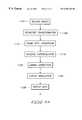
- FIG. 10is a flowchart of method steps illustrating DIP 210 's image processing, in accordance with one embodiment of the present invention.
- FIG. 11is a flowchart of method steps illustrating DOP 230 's image processing, in accordance with one embodiment of the present invention.
- the present inventionrelates to an improvement in electronic processing technology.
- the following descriptionis presented to enable one of ordinary skill in the art to make and use the invention and is provided in the context of a patent application and its requirements.
- Various modifications to the preferred embodimentwill be readily apparent to those skilled in the art and the generic principles herein may be applied to other embodiments.
- the present inventionis not intended to be limited to the embodiment shown but is to be accorded the widest scope consistent with the principles and features described herein.
- the present inventioncomprises an image processing apparatus for use in a display system, including a display device for viewing image, and a geometric transformation module that is configured to precondition said image data with geometric transformations to thereby compensate for characteristics of the display system.
- the geometric transformation modulemay include a spatial transformation module for redefining spatial relationships between image pixels, an alignment and rotation correction module for repositioning image pixels, a focus correction module for correcting image defocus, a distortion correction module for correcting image distortions, and a multi-frame correlation module for performing motion-compensated frame rate conversion.
- FIG. 2shows an image processing system 200 which includes a Display Input Processor (DIP) 210 , a Display Output Processor (DOP) 230 , and a buffer memory 240 , all coupled to a common databus 250 .
- System 200also includes an image modulator 245 (comparable to FIG. 1 modulators 110 , 112 , and 114 ) coupled to DOP 230 and to an external display screen 260 .
- DIP 210preferably receives images on line 2050 and reconstructs the images both spatially and temporally.
- DIP 210 outputsare processed by DOP 230 to enhance image visual quality.
- DOP 230 outputs, preferably in frame format,are stored in frame buffer 2400 which is part of buffer memory 240 .
- Buffer memory 240stores data for use by DIP 210 and DOP 230 .
- Frame buffer 2400which stores image data for outputting to image modulator 245 or to a digital memory (not shown), is preferably part of buffer memory 240 , but alternatively can be part of the digital memory, which can in turn be part of buffer memory 240 .
- Image modulator 245can be part of a CRT-based or LCD-based direct view system, displaying images that can be in pixel format on display screen 260 . However, if image modulator 245 is part of a projection system, then image modulator 245 provides images to be projected and enlarged onto display screen 260 . In a projector system, image modulator 245 is relatively small (inches) and may be either a stationary or a movable element. To increase the apparent resolution of the displayed images, a reverse super-resolution technique, in accordance with the present invention, adjusts the data values written into a stationary image modulator 245 at an increased frame rate.
- the inventionpreferably during each output frame in a cycle, moves image modulator 245 to effectively shift the display pixel matrix a fraction of a pixel in the X and Y directions, preferably at the screen refresh rate.
- System 200processes image data in a high-resolution internal format to preserve detailed image information, because such information can be lost in each of the various image processing steps if the internal image format has lower resolution than the output of image modulator 245 .
- System 200can assume that the processed image has four times (doubled vertically and horizontally) better pixel resolution than the (spatial resolution) output of image modulator 245 .
- FIG. 3is a block diagram of FIG. 2 DIP 210 , including image processing modules Analog Input Control 302 , Digital Input Control 304 , Compressed Input Control 312 , and Image Reconstruction (IR) 318 , all connected to a common databus 350 .
- DIP 210also includes one or more input data connectors 300 for receiving image data input to system 200 on line 2050 .
- the image datamay include one or more of analog video, digital video, non-tuned data, graphics data, or compressed data.
- Analog or digital video datamay be, in a native video format such as composite video, S-video, or some component YUV/YCrCb.
- Non-tuned datareceiving from a broadcast delivery system that may have many channels on a common carrier, may require a tuner included in or separate from DIP 210 so that relevant data can be tuned from the channels.
- Compressed datamay be in MPEG-2 format, which includes video and audio content, the data containing control or video overlay information for DOP 230 .
- MPEG-2 video datamay be in a variety of standard and high definition field or frame based formats that also may differ in the aspect ratio of the input image and may differ in the frame rate of the input image.
- Image data on line 2050may be encrypted for security and thus require decryption by DIP 210 .
- DIP 210also receives various control data including for example, selected inputs, data types, vertical blanking interval (VBI) data, overlay channel information for the on-screen display (OSD), and provides this control data to DOP 230 .
- VBIvertical blanking interval
- Each of the image processing modules, Analog Input Control 302 , Digital Input Control 304 , and Compressed Input Control 312preferably receives image data from connector 300 .
- a system microcontroller(not shown) preferably uses user-selected input controls to select image data, which is appropriately processed by each of modules 302 , 304 , and 312 , and then preferably stored in buffer memory 240 .
- the system microcontrolleralso uses the user input commands to control windowing for picture-in-picture displays, OSD information, and other system windowing capabilities.
- DIP 210preferably processes images in either YUV or RBG formats.
- Analog Input Control 302preferably includes an analog-to-digital converter (ADC) 3002 , which samples the analog data inputs and produces digital data outputs.
- ADC 3002to achieve high quality, samples its input data frequently and precisely enough that the image can be reconstructed from the sampled data points. Additional prior art techniques for sub-carrier demodulation are used to extract the video data from the analog input signal.
- Digital Input Control 304preferably includes a synchronization engine 3040 and processes digital data, which may be in a YUV video or a digital RBG format. Since the data is already in digital format, Digital Input Control 304 does not include an ADC. Digital Input Control 304 also uses high-speed digital data transmittal techniques that are described in the Institute of Electrical and Electronics Engineering (IEEE) standard 1394 , Low Voltage Differential Signaling (LVDS), and Panel Link. These standards include line termination, voltage control, data formatting, phase lock loops (PLLs), and data recovery to assure that Digital Input Control 304 properly receives the digital data input.
- IEEEInstitute of Electrical and Electronics Engineering
- LVDSLow Voltage Differential Signaling
- PLLsphase lock loops
- Compressed Input Control 312processes compressed data that usually includes audio, video, and system information.
- System informationmay provide information regarding the bitstream, such as if the video data is interlaced or non-interlaced.
- Compressed Input Control 312prior to decompression by decompression engine 3120 , preferably demodulates the compressed digital data. Alternatively, a preprocessing system (not shown) may demodulate the data and provide it to Compressed Input Control 312 .
- Compressed Input Control 312performing additional steps such as error correction, assures that it properly receives the data and that the data is not corrupted.
- Compressed Input Control 312may conceal the corruption.
- Compressed Input Control 312once having correctly received the data, de-multiplexes the data into audio, video, and system streams, and provides the audio streams to an audio subsystem (not shown) for decoding and playback.
- Compressed Input Control 312decompresses an encoded bitstream input, but retains relevant motion vector information for use in further processing.
- Bitstream Engine 3125combined with Decompression engine 3120 optimizes reconstruction of compressed input bitstreams, preferably MPEG-2 data, into enhanced video frames in a manner that has not been used in prior art video enhancement products.
- the bitstream informationincludes compliant video coded bitstreams, bitstreams with side information, layered codings for video and special bitstreams that have additional detail information leaked into a compliant bitstream.
- Lower-layer coded datacan reveal object shapes and other information that can be exploited to provide enhanced spatial and temporal rendering of blocks constituting images.
- Decompression engine 3120can perform the prior art steps of decoding a compliant MPEG-2 bitstream into a decoded picture.
- Bitstream Engine 3125processes the MPEG-2 bit streams including the image blocks (or macroblocks). Since most video frames within a sequence are highly correlated, Bitstream Engine 3125 exploits this correlation to improve rendering. Bitstream Engine 3125 also employs motion estimation techniques for motion compensated prediction as a method of temporal processing across image frames. Bitstream Engine 3125 can track the flow of video data prescribed by the prediction blocks belonging to the macroblocks within the bitstream, rather than re-estimating motion or creating the macroblocks similarly to a second pass encoding process. Bitstream Engine 3125 tracks the prediction blocks over several frames in which the temporal path of the prediction blocks delineates a coarse trajectory of moving objects.
- Bitstream Engine 3125preserves the motion vector information for later use in generating DOP 230 output frames in conjunction with motion compensated temporal filtering and reverse super-resolution.
- the informationcan also be used for constructing a special block filter for post decompression filtering of the coded input stream so that IR 318 can filter artifacts of block boundary edges.
- Buffer memory 240receives data from Analog Input Control 302 , Digital Input Control 304 , and Compressed Input Control 312 , and provides the data to Image Reconstruction 318 . Buffer memory 240 also stores IR 318 output data.
- IR 318preferably includes a Motion Estimator 3180 and receives image data from Analog Input control 302 , Digital Input Control 304 , Compressed Input Control 312 , or from buffer memory 240 .
- IR 318processes data based on data types. For example, if data in YUV format requires a conversion to the RGB domain, then IR 318 , through either mathematics calculations or a look-up table, converts YUV values to RGB color space. However, IR 318 preferably processes image frames while they are still in the YUV color space and, if required, RGB color space conversion is performed during one of the last image processing steps by DOP 230 .
- YUV datais often sub-sampled, that is, one UV pair may correspond to two or four Y values. Consequently, IR 318 uses the UV values to interpolate and create RGB pixels. If YUV data is interlaced then IR 318 converts the data from field based (sequential half frames) to frame based. IR 318 stores each field in buffer memory 240 , then filters, analyzes, and combines the fields to generate an input image frame. IR 318 , if required, retransmits the processed input frames in analog video format. Nevertheless, IR 318 preferably uses the processed image frames and the motion information created by DIP 210 while the frames and the information are still in their digital format.
- IR 318processes data, such as overlay information, relevant to image modulator 245 (FIG. 2 ), IR 318 provides such data to DOP 230 to later be combined with the image data frames. IR 318 may process multiple input data streams in parallel and provide such data to DOP 230 to later produce a picture-in-picture display of multiple images. IR 318 also does post decompression filtering based on block boundary information included in the input bitstream.
- IR 318For analog video inputs, IR 318 preferably uses techniques from, for example, Faroudja Labs and Snell & Willcox and Darim, that can sample and reconstruct input video, which includes composite, S-Video, and Component (Y, Cr, Cb) that may follow one of the industry standards such as Phase Alternative Line (PAL) or the National Television Standards Committee (NTSC).
- IR 318to spatially filter for high quality image frames, preferably uses various techniques for noise reduction, such as recursive, median filter, and time base correction.
- IR 318takes account of multiple input images and then, to enhance the resolution of those images, uses super-resolution techniques that employ data shared by different input frames to reconstruct an image, and thereby to produce each output frame. This cannot be done by independently using one input image at a time.
- the inventionis thus advantageous over prior art systems which use super-resolution techniques for generating high-resolution still images from a video sequence, but not for generating real time output frames.
- the super-resolution techniques used by the inventiondepend on a high correlation of the data between frames, and require a sub-pixel shift of the input images, typically based on slight movements of objects in the images.
- IR 318in correlating images to reconstruct output frames, uses motion vectors provided by Motion Estimator 3180 or preserved from the input bitstream.
- IR 318while generating still frames, can use mathematical equations from, for example, deterministic techniques of Projections On Convex Sets (POCS) and stochastic techniques of Bayesian enhancements.
- POCSProjections On Convex Sets
- Motion Estimator 3180When an image does not include MPEG-2 motion vector bitstream information, Motion Estimator 3180 preferably uses techniques such as optical flow, block matching, or Pel-recursion to estimate motion that tracks the image object motion in time. Motion Estimator 3180 can also use the same motion estimation techniques in conjunction with MPEG-2 motion vector bitstream information. Motion Estimator 3180 compares groups of pixels from one image field to those of subsequent and previous image fields to correlate object motion. Motion Estimator 3180 then records the detected motion relative to the field position so that DOP 230 , together with input frame information and IR 318 motion information, can later generate motion-compensated image frames. For compression systems, Motion Estimator 3180 finds the best match between frames, then codes the mismatches.
- techniquessuch as optical flow, block matching, or Pel-recursion to estimate motion that tracks the image object motion in time. Motion Estimator 3180 can also use the same motion estimation techniques in conjunction with MPEG-2 motion vector bitstream information. Motion Estimator 3180 compares groups of pixels from one image field to those of subsequent and previous image fields
- Motion Estimator 3180masks out motion vectors that do not meet a certain level of matching criteria, and tags the vectors that have a high level of matching so that these vectors can subsequently be used in more refined motion tracking operations, which are performed on smaller image blocks or on individual pixels.
- Motion Estimator 3180thus differs from prior art techniques in which video compression systems use the detected motion as one of the steps to compress the number of bits needed to represent a video sequence. Motion estimation is not used in a standard compliant decoder that simply performs motion compensation using the coded motion vectors and macroblocks. Consequently, the invention, via Motion Estimator 3180 , advantageously provides better quality images than prior art techniques.
- Motion Estimator 3180tracks motion on a sub(or smaller) block basis. For example, instead of on an 8 ⁇ 8 (pixels) block, Motion Estimator 3180 tracks motions on a 2 ⁇ 2 block, which tracks more refined motions. To reduce the need to track refined sub-blocks, Motion Estimator 3180 uses the course block matching differences to pre-qualify a block, and thus does not perform refined tracking on a blocks that are poor matches. Conversely, Motion Estimator 3180 does perform refined tracking on blocks that closely match.
- Decompression Engine 3120When receiving motion estimation vectors, such as those provided in an MPEG-2 data stream, Decompression Engine 3120 uses all of the vectors for compliant MPEG-2 Decoding. IR 318 then uses vectors with better block matching in analyzing refined motions for restoring multiple frames. Analyzing refined motions can produce motion vectors for sub-block pixel sizes, which can be used in multiframe reconstruction to better produce high resolution output frames.
- IR 318preferably separates its output images into video fields or frames, and creates a pointer to the start of each field (or frame). Either the actual field (or frame) data or a pointer to the field (or frame) data may serve as inputs to DOP 230 . Processing input video fields and producing frames that combine fields is useful for de-interlacing video in the image reconstruction process, which in turn is useful for increasing image resolution and for restoring the vertical detail that was lost during interlacing.
- IR 318 outputs (and DOP 230 outputs), having been reconstructed in accordance with the inventioncan have a higher resolution than can be supported by the number of pixels of image modulator 245 .
- IR 318 outputscan be stored in buffer memory 240 or in a metafile that includes a description of the image both in a spatial RGB frame buffer format and in a semantic description of the image objects, textures, and motions.
- the digital processing system of the DIP 210utilizes techniques such as super-resolution to produce images that have higher resolution than the individual input images. Other analog techniques are used in the DIP 210 combined with the super-resolution techniques for producing the high-resolution internal representation of the images.
- a geometric transformationmay also be used for processing the input data that includes a layered coding video bitstream.
- the foregoing geometric transformationmay either be performed as part of GT 404 in the DOP, or a Geometric Transform Module may alternately be included as part of the Image Reconstruction 318 in order to reconstruct input video frames.
- One technique for tracking image flowis to compare the coefficient data of the input bitstream to find the same patterns across time. If the same pattern is found, it may represent the flow of an object across the frames.
- the conjecture of image flowcan be further tested in the different layers to either confirm or reject the conjecture.
- Layered video codingis a technique for scalability which, for example, transmits multiple resolutions of video bitstreams where the higher resolutions utilize the bits from the lower resolution transmissions.
- a lower resolution decodercan discard the higher resolution bitstreams, and because the higher resolution bitstreams, instead of regenerating the entire bitstream, use the lower resolution bitstreams, the overall bandwidth for the higher resolution bitstream increases.
- the MPEG-2 specificationspecifies the complete profile for layered coding techniques, the invention provides additional control information accompanying the bitstream to comply with the MPEG-2 specification.
- Layered codingcan also be part of a non-MPEG-2 bitstream such as is proposed for future H. 263 extensions.
- Layered coding techniquesmay include other types of compressed data, such as wavelet data, to enhance a base level transmission.
- wavelet datamay be included as a layered stream of data.
- Wavelet datais compressed data that does not use the same DCT (Discrete Cosign Transform) compression scheme as the standard video portion of MPEG-2 video data.
- the wavelet datacould be coded as a private video data stream, or could be part of the video program stream and indicated in the program header information.
- the wavelet informationrepresents a higher resolution image for a complete or partial frame for some or all of the MPEG-2 frames.
- the IR 318combines the MPEG-2 data with the wavelet data. Because of the different characteristics of DCT and wavelet-based compression, the combination is used to produce a single high quality output frame.
- supplemental bitstream dataincludes motion estimator information that is an enhancement beyond the standard X and Y macroblock motion estimator vectors that are part of the MPEG-2 standard.
- motion estimator informationthat relates to the scale, rotation and sheer of image elements can also be provided as supplemental bitstream data.
- improved block matching for the encoder systemcan be achieved by using a scale-based compare instead of the X and Y displacement compare.
- a moving objectmay rotate instead of move in the X or Y direction.
- a rotation comparewill have a more accurate motion estimator comparison than standard motion vectors.
- IR 318can use the supplemental information relating to scale, rotation and sheer of image elements to reconstruct, preferably-using image transform techniques, a higher quality image from the input bitstream.
- IR 318uses instructional cues embedded in a bitstream for interpreting the video stream to utilize the macroblock and motion vector information for enhancing output images.
- the advantages of instructional cuesare very significant over the ability to extract frame-to-frame and GOP-to-GOP correlation without the cues.
- IR 318maintains complete GOPs in buffer memory 240 , IR 318 can utilize these cues which provide information across fields, frames, and GOPs.
- the enhanced decoder of the inventionuses the macroblock information from two GOPs.
- IR 318recognizing the enhanced instructional cues and improves image quality by using macroblock information from both a current GOP and an adjacent GOP.
- the inventionis therefore advantageous over prior techniques using standard decoders that do not keep previous fields and frame information any longer than required to decode and display output frames. Additionally, the standard decoder cannot recognize the instructional cues or utilize the motion vector only for the best match within adjacent frames. Also, while the enhanced decoder of the invention can use the instructional cues to achieve a higher quality display output, the standard decoder can use the video bitstream in a standard-compliant manner. Instructional cues require only a minor amount of data to be added to the bitstream.
- FIG. 4is a block diagram of FIG. 2 DOP 230 , which has a display map memory (DMM) 402 and image processing modules including Geometric Transformation 404 , Post GT Filtering 406 , Color/Spatial Gamma Correction 410 , Temporal Gamma Processing (TGP) 412 , Reverse Super-Resolution 414 , and Display Modulation (DM) 420 , all connected to a common databus 450 .
- Databus 450satisfies system bandwidth and concurrency requirements for parallel image processing.
- DOP 230also connects to buffer memory 240 , which stores data frames for use by each of the processing modules 402 , 404 , 406 , 410 , 412 , 414 , and 420 , although each of these modules may include a local memory buffer (not shown).
- DOP 230receives DIP 210 outputs either directly or via buffer memory 240 .
- DOP 230can use pointers (if applicable) to directly access DIP 210 output data.
- DOP 230also receives multiple DIP 210 output images for performing picture-in-picture operations where a single image frame includes more than one processed input video frame.
- DOP 230combines overlay data both from the input coded data and from any on-screen display (OSD) information such as a user menu selection provided by the system microcontroller.
- OSDon-screen display
- DOP 230processes its input images and outputs image data including display coordination for both video and data output, and data and control signals for each R, G, and B image color component.
- Frame buffer 2400(FIG. 2) can store DOP 230 outputs.
- DOP 230The digital processing of DOP 230 is distinguishable from prior art systems through the performance of various operations, including the geometric transformations of the present invention. While traditional filtering techniques may be used by DIP 210 and after GT, the GT 404 distinguishes this system from prior art in the ability to perform the affinity mapping of the DIP output to the image modulator to pre-compensate for distortions that occur during projection that occurs from the modulator to the display screen.
- DMM 402stores data corresponding to image modulator 245 (FIG. 2) characteristics at chosen pixel or screen locations.
- DMM 402where applicable, also stores a memory description corresponding to each display pixel or a shared description of groups of display pixels or pixel sectors. Because the description does not change on a frame-by-frame basis, DMM 402 preferably reads the description only once during the display process.
- DOP 230uses the description information to generate image frames.
- DMM 402when reading data, uses a set of control registers (not shown) that provide references to the data blocks.
- DMM 402 datavaries and may include, for illustrative purposes, manufacturing-related information, system configuration information, and user data.
- Manufacturing-related informationmay include, for example, a map of locations, usually at assembly time, of defective or weak pixel display bits, correlation data of ideal radial imperfections and of optically distorted projection, and correlation data for alignment points for image modulator 245 .
- System configuration informationthrough an automatic self-calibration, may include, for example, a registration map having adjustable intensity values for each R, G, and B color component and the color component pixel offset at given locations.
- DMM 402where applicable, preferably uses sensor techniques, such as sonar range finding, infrared range finding, or laser range finding to measure distances from a projector (not shown) to different parts of display screen 260 . DMM 402 then uses these measurements to mathematically characterize and model a projection display system. DMM 402 thus allows projecting images onto a mathematical approximation of a display screen 260 surface.
- User dataincludes user preference information such as brightness, color balance, and picture sharpness that are input by a user during a setup sequence.
- DMM 402preferably provides data, either directly or through buffer memory 240 , to Geometric Transformation module 404 .
- Geometric Transformation 404advantageously redefines the spatial relationship between pixel points of an image to provide to frame buffer 2400 compensated digital images that, when displayed, exhibit the highest possible image quality.
- Geometric transformationalso referred to as warping, includes image scaling, rotation, and translation.
- Geometric Transformation 404resamples data to produce an affinity output image that can readily map onto FIG. 2 image modulator 245 .
- the Geometric Transformation 404 output data points, due to scaling or resampling,may not correspond one-to-one to data points of the image modulator 245 grid.
- DOP 230includes Post Geometric Transform Filtering 406 to filter the transformed data samples from Geometric Transformation 404 and thereby produce an output pixel value for each data point of image modulator 245 .
- Post Geometric Transform Filtering 406uses spatial filtering methods to smooth the image and to resample, and thus properly space, the data samples.
- Geometric Transformation 404also improves display image characteristics related to image modulator 245 and the display system. For image modulator 245 screen regions that have more image modulator 245 pixels than screen 260 pixels, Geometric Transformation 404 adjusts the pixel values by a spatial filtering to reduce differences in neighboring pixel values. Consequently, the corresponding image (stored in frame buffer 2400 ) is smooth and does not contain artifacts. For screen display regions that have fewer image modulator 245 pixels than screen 260 pixels, Geometric Transformation 404 uses edge enhancement filtering to increase differences between neighboring pixel values to pre-compensate for distortion that will be introduced when image projection spreads out neighboring pixels.
- Geometric Transformation 404preferably uses filtering algorithms, such as nearest neighbor, bilinear, cubic convolution, sync filters, or cubic spline interpolation, to process images and thus produce accurate interpolated image pixel values. Further, where multiframe reconstruction requires, Geometric Transformation 404 uses time-varying multiframe filtering methods including deterministic techniques such as projection onto convex sets (POCS), and stochastic techniques such as Bayesian filtering. Based on the computation complexity, Geometric Transformation 404 chooses an appropriate filtering technique.
- filtering algorithmssuch as nearest neighbor, bilinear, cubic convolution, sync filters, or cubic spline interpolation
- Geometric Transformation 404can improve image deficiencies related to the screen 260 environment. Geometric Transformation 404 performs a spatial projection which warps the image to compensate for a curved display screen 260 as is usually used in front projection theater systems, and subsequently uses bitstream information to improve the image. For example, if it can acquire the depth of moving objects, Geometric Transformation 404 can reduce the distorted motions at the edges of a curved screen 260 . Geometric Transformation 404 constructs an optical flow field of the moving objects along with the object distance information. Geometric Transformation 404 then uses motion adaptive filtering to construct a sequence of output frames that position the objects at the proper spatial coordinates in the time domain.
- Geometric Transformation 404thus, during projection on a curved screen 260 , conveys the proper motion of all objects in a scene. Geometric Transformation 404 also works in conjunction with an optical correction to improve distortions resulting from the different focal distances from a projector (not shown) to different parts of screen 260 . Geometric Transformation 404 uses range finding techniques (discussed above) to construct a model of the screen 260 environment and then uses the information from the model and the optical system to mathematically construct a formula to compensate for image distortions. Geometric Transformation 404 , to correct a warping distortion produced by an optical system, uses the same mathematical basis for a flat screen geometric transformation to apply to a curved screen.
- the transfer function for the path from the image modulator to the display screenchanges if the display screen is curved.
- the curve of the display screenbecomes part of the transfer function of the display system.
- the geometric transformationcan incorporate the curved display screen contribution to the transfer function and compensate accordingly.
- the benefit of incorporating the screen curvature in the transfer functionis that the geometric transformation operation only needs to be performed once to compensate for both the system distortions and screen curvature.
- Geometric Transformation 404uses special processing, similar to the curved screen 260 processing, for various head-mounted displays (HMDs).
- HMDis a display unit combined with a helmet or glasses that a user wears, and usually includes two image modulators 245 , one for the right eye and one for the left eye.
- HMDsare useful for a single viewer and, because of their physically smaller area, they typically display high quality images.
- Geometric Transformation 404treats image spatial projection with warping onto a curved screen 260 in the context of 3D graphics.
- Geometric Transformation 404considers a display image frame as a 2D texture and considers a curved surface as a 3D surface.
- Geometric Transformation 404maps the 2D texture onto a surface that is the mathematical inverse of the curved screen 260 .
- Geometric Transformation 404thus pre-corrects the image frame so that, when projected, the mapped image will have filtered out the distortions associated with a curved screen 260 .
- Geometric Transformation 404preferably uses techniques such as anisotropic filtering to assure that the best texture is used in generating output pixels.
- Geometric Transformation 404also preferably uses filtering techniques such as sync filters, Wiener deconvolution, and POCS, and/or other multipass filtering techniques to filter the images off-line and then output the filtered images onto a film recorder. Geometric Transformation 404 preferably allows more computationally-intensive image operations to be performed off-line.
- filtering techniquessuch as sync filters, Wiener deconvolution, and POCS, and/or other multipass filtering techniques to filter the images off-line and then output the filtered images onto a film recorder.
- Geometric Transformation 404preferably allows more computationally-intensive image operations to be performed off-line.
- Geometric Transformation 404processes video as 3D texture mapping, preferably using systems that accommodate multiple textures in images.
- Geometric Transformation 404can use high quality texturing techniques such as bump mapping and displacement mapping which apply multiple texture maps to an image.
- Geometric Transformation 404to model the graininess inherent in film, may apply multi-surface texturing to give video a more film-like appearance.
- Geometric Transformation 404can allow a user to select the graininess modeling feature as part of the setup procedure, similar to selecting room effects such as “Hall,” “Stadium,” etc., in an audio playback option.
- Geometric Transformation 404can process digital data from a multi-camera system to improve the focus, and thereby provide higher quality images for image modulator 245 .
- Geometric Transformation 404evaluates which of the multiple camera views provides the best focus for an object and then reconstructs the object in proper perspective.
- Geometric Transformation 404then combines the multiple camera views on a regional or object basis to produce output images. Multiple camera views can also be used for multiframe image reconstruction.
- Geometric Transformation 404can also use multi-camera bitstream information included in the image data to determine the object depth of a scene and to construct a 3D model of the shape and motion pattern of the moving objects. Geometric Transformation 404 then uses the same bitstream information to solve problems related to a curved screen 260 projection to achieve proper object motion completely across the screen 260 .
- Geometric Transformation 404can also improve auto stereoscopic 3D display systems in which multiple camera channels present a binocular display and each of a viewer's eye sees a different monocular view of a scene.
- the positional informationis used during the display process so the viewer will see the camera views from the proper right and left eye viewpoints.
- supplemental bitstream informationcan explicitly indicate objects in the video, as well as the depth and motion of these objects.
- the GT 404can use the positional camera information as well as explicit object information in order to perform the transforms for the display output data.
- Geometric Transformation 404can construct each of the monocular views in accordance with the focus and motion adaptive filtering techniques described above.
- the techniques for matching viewer positional information and multiple camera viewscan be used for multiple screen entertainment systems. These entertainment systems may involve some combination of moving and stationary screens as well as moving or stationary viewers.
- One example applicationis a theme park ride where the viewer sees multiple screens while he is moved along the ride path.
- the ride pathmay either be pre determined or may be interactively determined.
- the Geometric Transform modulecan be used for performing special effects and real time transitions between video streams to improve the user interface. For example, when changing channels, instead of abruptly changing from one channel to another, the geometric transform module can fade one channel and blend it with the new channel. Fades and blends typically keep the video pixels at the current locations and perform weightings to increase or decrease the intensity of the pixel values. This is also used for menu overlays for such features as on line program guides and user setup menus.
- the Geometric Transform modulecan also perform more advanced transitions such as wipes or warps. These more advanced transitions involve warping the video image by changing the spatial coordinates of the video image.
- One technique for performing these effectsis to use video as a texture map and to apply the video texture map in real time to the changing display map.
- GT 404can also be used to process an image-key meta data stream, which is a hybrid decoding type for a bitstream of combined video and synthetic data.
- This image key information techniqueallows the enhanced decoding system of the invention to generate enhanced outputs for environments where standard MPEG data may not be sufficient.
- the image key informationrecords the positional information and environmental information for the “key” area in the video image.
- the meta data streamincludes an additional description of the same key area of the image. This description is preferably generated synthetically.
- the inventioncan encode a hockey game such that the encoding system tracks the hockey puck and an image key meta data stream is included in the bitstream.
- the enhanced decoderlater uses the same key meta data stream to display an enhanced hockey puck that can be seen more easily by viewers.
- the inventionalso allows a user to vary the puck highlighting to suit the user's viewing preferences and match the user's viewing environment. A fixed puck highlighting without an option to vary the highlighting may be objectionable to viewers.
- the inventionallows a broadcaster to appropriately broadcast an image of a can of soda displaying a label of either Coke® or Pepsi® because the invention allows broadcasting the soda can along with a key meta data stream that represents the label.
- the inventionallows the desired label to be superimposed on the soda can.
- the inventioncan use viewer profile information to determine which product (here, Coke or Pepsi) is to be displayed.
- image key informationmay include object information such as the depth of the object in a field.
- the inventionuses this type of information to project images on a curved surface, such as in a digital panoramic system.
- the inventionuses the depth information to adjust output pixels and thus varies the spatial position of an object to correct for the curved surface. Because adjusting the output pixels can cause complications, such as how these adjustments will affect the surrounding pixels, the invention, via the bitstream encoder, uses a fencing technique to lessen the impact of these adjustments.
- the inventionmarks the macroblocks that are part of the object in the video portion of the stream as “off limits,” that is, these macroblocks are not to be used for motion vector prediction between frames. The invention thus allows substituting or modifying the objects or macroblocks without affecting the surrounding blocks.
- the inventioncan also use supplemental data streams in 3D camera systems that provide supplemental information, such as, what is behind the object being keyed, which is often useful for DOP 230 in the pipeline and is passed along in the pipeline.
- GT 404the ability of GT 404 to combine video data along with synthetic data and optimize it for a display system distinguishes it from prior art systems.
- the operations of the GT 404optionally can be implemented as part of a 3D graphics pipeline using traditional texture mapping techniques.
- synthetic image datacan be mapped onto a portion of the video frame, where the synthetic image can be represented by a 2D or 3D data set.
- Color and Spatial Gamma Correction 410converts YUV to RGB color space and determines the intensity values for each of the R, G, and B color components. Those skilled in the art will recognize that a color space conversion is not necessary if it has been done previously or if the image is otherwise already in the RGB color space.
- Color and Spatial Gamma Correction 410preferably uses a look-up table, in which each of the R, G, and B color components has values corresponding to color intensities, to translate image colors. Each R, G, and B intensity value represents an index into the look-up table, and the table provides the output (or “translated”) value. Color and Spatial Gamma Correction 410 independently processes each R, G, or B color component.
- Color and Spatial Gamma Correction 410maps each color component based both on a combination of individual RGB values and on RGB values of surrounding pixels. For example, if FIG. 2 image modulator 245 requires a certain brightness for an identified area on display screen 260 , then Color and Spatial Gamma Correction 410 may use the RGB values of the pixels in the identified area and of the pixels in the neighboring area. Color and Spatial Gamma Correction 410 uses mathematical calculations, or preferably a color look-up table (CLUT), to provide the RGB values for the desired image outputs. Color and Spatial Gamma Correction 410 prefers using a CLUT instead of mathematical calculations because a CLUT allows a non-linear mapping of the input RGB values to the translated (output) RGB values.
- CLUTcolor look-up table
- a non-linear mappingenables input colors represented by RGB values to be adjusted (emphasized or de-emphasized) during the mapping process, which is useful for crosstalk suppression and for compensation of shortcomings in a color gamut of image modulator 245 .
- TGP 412assures that the time related representation of an image is as accurate as possible. TGP 412 thus, based on a previous frame value and a known transfer function of the display modulation system, adjusts its output values to provide a desired output value during a desired frame. TGP 412 independently processes each R, G, or B color component and compensates for modulating transition characteristics that, due to the nature of an LCD image modulator 245 , are not purely digital. TGP 412 also overdrives the LCD image modulator 245 to compensate for the LCD material characteristics, so that the desired output can be achieved more quickly. Consequently, TGP 412 overcomes the video quality limitation of prior art systems having materials that produce blurred outputs. TGP 412 can also reduce the cost of the display system because the materials used for image modulation in prior art systems that provide faster image response are usually expensive. TGP 412 is described in detail with reference to FIGS. 6 and 7.
- RSR 414performs a superset of the frame rate conversion process for converting between disparate input and output frame rates, and can improve display quality when intended display images have a higher apparent resolution than can be supported by the number of pixels of image modulator 245 .
- RSR 414simulates higher resolution outputs by sequencing lower resolution images at higher frame rates.
- RSR 414then shifts by the same pixel (or pixel fraction) amount the pixel matrix representing each RSR image block.
- RSR 414shifts the pixel matrix block Y times, once for each RSR frame, and each shift is by the same pixel (or pixel fraction) amount.
- the number of pixel fractions to be shifteddepends on the physical characteristics of the display system and of image modulator 245 . Where a system adjusts the position of the viewed image, the shift fraction corresponds to the physical movement of the viewed displayed image. Where there is no actual movement of the displayed image, the fractional adjustment is based on the physical nature of the display device such as the pixel size relative to the size of image modulator 245 and to the projection characteristics of the system.
- RSR 414then produces each RSR frame with a motion-compensated weighted filtered center so that the center of the input image for each RSR frame is maintained such that no motion artifacts are introduced.
- a pixel-matrix weighted filtered centeris the center of a pixel matrix taking account of filter weights in a filter transfer function. Filter weights, varying depending on the filter characteristics, are the values (usually of multiplications and additions) which are combined with the input pixel values to produce the filtered image output.
- a filter transfer functionuses filter weights to transform an input image to an output image. Output image pixels, based on a transfer function, can be adjusted to move the corresponding image.
- RSR 414preferably uses image blocks having 8 ⁇ 8 to 256 ⁇ 256 pixels where each block has uniquely processed motion information. For static images, RSR 414 produces a sequence of frame-rate-adjusted output frames that are based on the difference between the input and the output frame rate. For motion pictures, RSR 414 , at the time of the output frame, portrays the intermediate position of the image and compensates for the image motion. With increased processing, each pixel or sub-pixel will have its motion information processed uniquely. RSR 414 is further illustrated with reference to FIGS. 8 and 9.
- the GT 404determines the extent and need to perform the image transformation.
- the various processing stages of the GT 404are able to use blocks of the original image in order to perform the processing and create the new output blocks.
- a variety of sampling techniquesare used on the output of the DIP to produce the data for the DOP.
- the DOPgenerates the pre-compensated data for the image modulator.
- Geometric transformation of digital imagesis a sampling process and is susceptible to aliasing artifacts. Simple sampling techniques such as point sampling are not sufficient to avoid aliasing. Instead, techniques such as area sampling, supersampling, adaptive supersampling, stochastic sampling, poisson sampling, jittered sampling, point diffusion sampling and adaptive stochastic sampling. Other more advanced convolution techniques are also used in sampling and even after sophisticated sampling is used, post sample filtering is required.
- Display Modulator (DM) 420preferably receives DOP 230 (processed) output data, and controls sending of that data to image modulator 245 .
- DM 420may include control for timing updates with respect to the display timing.
- DM 420 outputsmay be analog but preferably are digital and include separate data and control signals for each R, G, and B color component.
- DM 420 outputsfor example, can be on one or two 24-bit digital busses that drive a raster scan.
- DM 420may use voltage or frequency modulation techniques for outputs to drive image modulator 245 .
- DM 420outputs, for a flat panel display, include row and column drivers, and for each active matrix TFT, passive matrix LCD display, or other display type that requires them, includes voltage level specifications. Prior to modulating images, DM 420 determines the simplest way, the frequency, and the values represent the data to be written to image modulator 245 . DM 420 uses TGP 412 and RSR 414 , which include both compensation for the time response associated with image modulator 245 and an algorithm that increases the display update rate (or refresh rate), to increase the perceived resolution of image modulator 245 .
- FIG. 5is block diagram of Geometric Transformation 404 of FIG. 4 and includes image processing modules Spatial Transformation 502 , Alignment and Rotation Correction 506 , Focus Correction 508 , Distortion Correction 510 , Resampling 512 , and Multiframe Correlation 514 , all interconnect via a common databus 550 .
- These processing modulesalthough they are shown as separate blocks, can be a single programmable processor performing the functions of the various modules.
- the general mapping functioncan relate the output coordinate system to that of the input.
- Both the flatness of the screen and the distortion produced by the optics of the systemdefine the transfer function of system 200 .
- the geometric transform 404 hardware or software of system 200takes this transfer function and effectively inverts it so that the processed input video data is written to the image modulator so that the transfer and inverse transfer functions counter each other and the display at the screen most accurately portrays the input data.
- An important aspect of being able to generate the best data values for the image modulator 245is the ability to apply super-resolution techniques to the input data so that higher resolution intermediate images can be used for the generation of the image modulator data.
- Spatial Transformation 502redefines the spatial relationship between image pixel points.
- Spatial Transformation 502for example, in an X-Y alignment in a projection system with three image modulators 245 , allows each image modulator 245 to have extra pixel rows and columns.
- Spatial Transformation 502then digitally adjusts the image pixels in the X-Y plane and writes the adjusted pixel data to image modulators 245 . For example, if the pixel adjustment is by an integer, Spatial Transformation 502 shifts the old imaging pixel address by the integer number of pixels to adjust. However, if the adjustment is a non-integer then Spatial Transformation 502 resamples the image with a weighted filtering algorithm to acquire new pixel values.
- Spatial Transformation 502also deals with one-dimensional skew, tangential symmetry, aspect angle, and scale related distortions of image modulator 245 . Spatial Transformation 502 uses resampling and weighted filtering algorithms to correct for such distortions on a pixel line by pixel line basis. Spatial Transformation 502 can perform texture mapping as in a traditional 3D rendering process.
- Alignment/Rotation Correction 506deals with two dimensional skew, tangential symmetry, aspect angle, and scale related distortions of image modulator 245 .
- Alignment/Rotation Correction 506for each R, G, and B color component, uses resampling and weighted filtering to reposition pixels in the both horizontal and vertical directions so that, when output, each color component is positioned in the proper locations across the entire image.
- Alignment/Rotation Correction 506also repositions pixels to rotate display images.
- Alignment/Rotation Correction 506to correct rotational misalignment for three image modulators 245 or geometric distortion from lenses, performs a geometric transformation to pre-compensate the images.
- Focus Correction 508improves non-uniform defocus, including defocus introduced by image modulator 245 optics. Focus Correction 508 , to account for focus problems of display screen 260 , preferably filters the image to pre-compensate the digital data representing the image. If a display screen 260 area has more image modulator 245 pixels than display screen 260 pixels, then Focus Correction 508 , on a single frame basis, uses noise filtering techniques to apply linear filters, nonlinear filters, and adaptive filters. Focus Correction 508 additionally uses techniques based on POCS or other adaptive filtering techniques to pre-compensate for anticipated focus blurring.
- Focus Correction 508uses convolution techniques or reverse filtering techniques to perform edge enhancements to pre-compensate for the pixels being spread out and the image being blurred during projection.
- the spatial spread of the image due to the display systemis characterized as the display system Point Spread Function (PSF).
- PSFPoint Spread Function
- Distortion Correction 510corrects image distortion, including keystone effects.
- Distortion Correction 510provides each image with a scan line having a different scale factor to precompensate for projection distance differences.
- Distortion Correction 510filters the image by permitting the image to use fewer pixels on image modulator 245 , so that, when projected, images on screen 260 will be proportioned properly.
- Distortion Correction 510also corrects for radial distortion introduced by lens systems. In regions where radial distortion increases the pixel density of display screen 260 , Distortion Correction 510 uses a spatial filter to reduce any differences between neighboring pixel values. Consequently, the corresponding image is smooth and does not contain artifacts, including high frequency artifacts. For screen display 260 regions that have fewer pixels than display screen 260 pixels, Distortion Correction 510 uses a filtering technique to perform edge enhancements which increase differences between neighboring pixel values. This pre-compensates for the PSF distortion which will be introduced during display where neighboring pixels are spread out. Consequently, the display process smooths out images that would have had sharp edges to have a more uniform appearance. Distortion Correction 510 preferably acquires specific distortion patterns from DMM 402 .
- Resampling 512translates the pixel values from high resolution grids to new pixel values on image modulator 245 grids.
- Multiframe Correlation 514improves multiple frame display quality. For both increased and decreased pixel representations,
- Multiframe Correlation 514uses algorithms such as Wiener deconvolution to exploit the temporal correlation between frames.
- Multiframe Correlation 514uses multiframe techniques that process more than one input image frame to construct an optical flow field, which is further processed to construct output frames.
- IR 318can provide frame inputs to Multiframe Correlation 514 .
- these frame inputsmay be part of the compressed data input to Compressed Input Control 312 .
- Multiframe Correlation 514can use Bayesian filtering or POCS techniques to extract multiple frame information and motion vectors showing relationships between frames from a compressed bitstream.
- Multiframe Correlation 514also converts an input frame rate to an output frame rate, for example, from 24 frames per second (fps) to 60 fps.
- Multiframe Correlation 514thus, from the sequence of 24 input frames, generates 60 unique and distinct output frames wherein all moving objects are motion-compensated so that, at the time when they are displayed, they are at the proper spatial coordinates.
- Information for generating proper output framesresults from the input frame, motion estimation information, and object motion prediction.
- Motion estimation informationis either part of the MPEG-2 input bitstream or generated by Motion Estimator 3180 during image input processing.
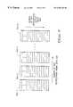
- FIG. 6illustrates the operation of FIG. 4 TGP 412 , which receives desired output frame data 600 on line 6000 and previous frame data 604 on line 6040 , and outputs value 610 on line 6100 .
- lines 6000 , 6040 and 6100are part of databus 450 (FIG. 4 ).
- Desired output frame data 600 , previous frame data 604 , and adjusted output value 610are preferably in R, G, and B color component values.
- Desired output frame 600preferably has been sampled by Resampling 512 (FIG. 5) and is provided from Geometric transformation 404 , Post GT Filtering 406 and Color/Spatial Gamma Correction 410 .
- Previous frame data 604corresponds to the last frame data of desired output frame 600 that was output to image modulator 245 .
- Previous frame data 604is preferably stored in memory buffer 240 because previous frame data 604 cannot be efficiently read from image modulator 245 , which does not provide a reliable or fast read path.
- TGP 412processing each R, G, and B color component independently for each pixel, uses previous frame data 604 to select a look-up table in temporal look-up table (TG LUT) 608 , and from that selected table uses desired frame data 600 to provide adjusted value 610 .
- TG LUTtemporal look-up table
- FIG. 7illustrates the operation of FIG. 6 TG LUT 608 , which includes translation tables 704-1 to 704-N.
- the number of bits representing desired output value 600determines the depth of a table 704 , that is, the number of (Red, Green, or Blue) color component intensities a table 704 can store.
- FIG. 8 and FIG. 9illustrate the function of RSR 414 operating on a video sequence containing images that have a spatial resolution four times higher than can be supported by the number of pixels of image modulator 245 .
- FIG. 8shows, for example, a video image 800 having an 8 ⁇ 8 pixel resolution and a video image 804 of image modulator 245 (FIG. 2) having a 4 ⁇ 4 pixel resolution.
- the video sequence transfer rateis 24 fps.
- RSR 414filters 24 fps frames into 96 (4 ⁇ 24) fps images, and thus uses the higher spatial resolution at a higher temporal display rate, although each frame has a lower spatial resolution.
- FIG. 8shows, for example, a video image 800 having an 8 ⁇ 8 pixel resolution and a video image 804 of image modulator 245 (FIG. 2) having a 4 ⁇ 4 pixel resolution.
- the video sequence transfer rateis 24 fps.
- RSR 414filters 24 fps frames into 96 (4 ⁇ 24) f
- RSR 414block by block, spatially filters frames 900 , 904 , 908 , and 912 into transitional frames 9000 , 9040 , 9080 , and 9120 , respectively.
- RSR 414in generating frames 9000 , 9040 , 9080 , and 9120 , keeps the pixel matrix weighted filtered center of each frame 900 , 904 , 908 , and 912 constant or such that motion artifacts are not generated.
- RSR 414then filters frame 900 to frame 9000 , that is, RSR 414 resamples each frame 900 block such that each frame 900 block output pixel matrix is shifted, for example, half a pixel to the bottom and half a pixel to the right.
- RSR 414thus causes the effective center, or the weighted and spatially filtered center, of each pixel in a frame 900 block to shift to the center of what becomes the upper left quadrant of that pixel.
- Spatially filtering each block by blockallows the filter coefficients to more accurately represent the desired block outputs. Combining the block outputs produces the new output frame.
- spatially filtering each frame 900 to frame 9000causes the viewable area of frame 9000 to be one pixel less on each edge than that of frame 900 .
- RSR 414filters frame 904 to frame 9040 (again on a block by block basis). Consequently, the frame 904 output pixel matrix is shifted half a pixel to the left and half a pixel to the bottom (the weighted center of each pixel shifts to that pixel's upper right quadrant).
- RSR 414filters frame 908 to frame 9080
- RSR 414filters frame 912 to frame 9120 .
- the frame 908 output pixel matrixis shifted half a pixel to the left and half a pixel to the top (the weighted center of each pixel shifts to that pixel's lower right quadrant), and the frame 912 output pixel matrix is shifted half a pixel to the right and half a pixel to the top (the weighted center of each pixel shifts to that pixel's lower left quadrant).
- RSR 414can substitute any “pixel fraction” for “half a pixel” in the above discussion.
- the pixel fractionis determined by a system designer considering the projection path from image modulator 245 to display screen 260 and/or the pixel characteristics such as the grid spacing of the pixels versus the physical size of image modulator 245 . In this preferred embodiment, shifting and filtering images and increasing the display rate produces higher resolution display images.
- the inventioninstead of just shifting the pixel matrix, can physically move the viewed images at the display screen refresh rate, by moving either the direct screen display device 260 or image modulator 245 .
- the inventionmoves image modulator 245 .
- the inventionuses any of several techniques including Piezo electronics or micromachines to move modulator 245 .
- the inventionuses Piezo electronics to vibrate image modulator 245 , and thereby shifts modulator 245 in the X and Y directions. Assuming image modulator 245 and the pixel matrix representing an image are both square, Piezo electronics, according to the invention, uses the following equation to move image modulator 245 :
- D mis the distance in inch to move image modulator 245
- D dis the desired distance in a unit of a pixel size to move the image pixel matrix
- Sis the size in inches of an image modulator 245 side
- Image modulator 245while being moved to shift an image pixel matrix, uses data in the four frames 900 , 904 , 908 , and 912 to sample pixels for each image location of an output image, and from the four corresponding locations from the four frames 900 , 904 , 908 , and 912 , produces one location to display.
- Moving image 245is in repeated cycles. Further, during each cycle, image modulator 245 uses a corresponding sample from each of the four frames 900 , 904 , 908 , and 912 .
- the inventioncan use other techniques that allow the illusion of moving modulator 245 without physically moving any parts.
- the inventioncan use more than one LCD mirror to reflect the image through the display projection system where each mirror has a slightly different projection angle.
- the inventionuses the LCD mirrors to create a sequence of projected images with slightly different positions.
- the inventioncan also use lenticular lens, LCD mirror, or multi-layered micro display technologies to move the viewed image without moving image modulator 245 .
- RSR 414produces, for static images, an output which is stable to a viewer because human vision interpolates multiple images to form one continuous image view.
- RSR 414uses motion-adaptive filters, including median filters, that include motion tracking to filter each block constituting each image frame ( 900 , 904 , etc.).
- Motion-adaptive filteringaccounts for positions of moving objects between intermediate frames created by RSR 414 . For example, an object may be moving along an X axis from a position 6 in frame i to a position 10 in frame k. If RSR 414 creates an intermediate frame j, then the moving object will be positioned at location 8 in frame j, which is half way between location 6 in frame i and location 10 in frame k.
- RSR 414used in combination with motion-adaptive filtering, weights the RSR frames and compensates for motions between frames.
- RSR 414also uses the block-based motion estimation from the MPEG-2 motion vectors or from Motion Estimator 3180 to track motion in the image.
- RSR 414first identifies the motion blocks of the objects within an image, then allows successive output frames to utilize the image object motion information and to move the center weighting for the corresponding pixels to correlate to the object motion.
- RSR 414also uses multiple input frames or fields to track the trajectory and velocity of moving objects and thereby predicts the object spatial position in a frame. As a result, RSR 414 greatly reduces or even eliminates motion artifacts.
- RSR 414thus can produce images having higher resolution than can be supported by the number of pixels of image modulator 245 , and provide a high resolution system without incurring increased cost as is usually found in prior art high resolution systems.
- RSR 414can extract the motion tracking information directly from the bitstream, which preferably includes the data to discern which blocks contain moving objects and the object movement patterns. Alternatively, RSR 414 can extract the same motion tracking information from post-decoded (or decompressed) frames. RSR 414 then provides the motion tracking information to the filtering algorithms. RSR 414 can improve FEDs and the class of displays defined as those in which each pixel is made up of a matrix of emitting elements. For example, RSR 414 combines the FED mesh cell configuration and its address control to perform RSR and, from high resolution images, sequences a high resolution output using a FED that has a lower number of addressable pixels.
- RSR 414uses the same techniques for generating the spatially filtered RSR frames to determine the sequence of lower resolution images.
- RSR 414then, taking advantage of the sub-pixel addressing within a pixel that is unique to the microtips and mesh structure of the FED, writes the sequence of the frames within the FED sub pixel addressing.
- the resolution of FEDsis defined as the ability to individually address a pixel.
- FEDscan be designed with an internal function to adjust the mesh cell emitter positions for data already stored in the pixels. In this way the position of the image is moved without a new image being loaded into the pixels. Sequentially modulating images within the FED mesh structure constructs a display image that has higher resolution than the addressable resolution of the FED display would otherwise allow.
- FIG. 10is a flowchart illustrating DIP 210 's image processing steps in selecting and reconstructing images.
- DIP 210where applicable, preferably creates a database to store motion information for later use by DOP 230 .
- system 200via connector 300 of DIP 210 , receives input images.
- a microcontrollerpreferably selects one or more input images and provides each image to appropriate image processing modules Analog Input Control 302 , Digital Input Control 304 , and Compressed Input Control 312 .
- Each processing module 302 , 304 , and 312in step 1012 , samples, and thereby recovers, the input images.
- Analog Input Control 302may discard unnecessary or repeated input fields.
- Compressed Input Control 312via Bitstream Engine 3125 , analyzes the compressed input streams and selects one or more picture streams for analysis and processing.
- Bitstream Engine 3125records the motion information from the bitstream for use in the image reconstruction steps 1020 , 1024 , and 1028 , and by the DOP 230 .
- Bitstream Engine 3125based on a quality trade-off decision, can select a single picture or decode multiple pictures. This is because system 200 may not have the compute power required to process multiple input streams at full quality. If multiple pictures are to be displayed simultaneously, each picture will only be a portion of the total display output and thus can cause lower visual display quality than if a single picture were used for the full output.
- Bitstream Engine 3125while sampling a compressed stream, may extract multiple picture streams, and, if required, reduce the complexity of the multiple picture streams to be processed.
- each processing module 302 , 304 , and 312preferably formats the images and stores them in buffer 240 .
- Decompression Engine 3120preferably uses the MPEG-2 decompression steps to convert the compressed bitstream into a decompressed and decoded picture.
- Decompression Engine 3120can simultaneously decompress more than one compressed picture stream for multiple picture displays including advanced picture-in-picture displays and multi-camera systems.
- Decompression Engine 3120can decode both layers for use by the Image Reconstruction 318 .
- Image Reconstruction 318spatially filters each image frame to reconstruct 2D images.
- Spatial filteringincludes various techniques for noise reduction so that the filtered image does not include artifacts that were not part of the original image. Filtering is preferably applied across the entire input image based on the data values. However, filtering can use additional information, such as spatial position of the decoded macroblocks, that is provided by the Bitstream Engine 3125 in cases where, for example, the MPEG-2 data has been decompressed by Decompression Engine 3120 . This positional information allows the filter to reduce or eliminate artifacts from boundary edges from the decoded macroblocks while performing the more traditional spatial filtering on the other portions of the image.
- Image Reconstruction 318performs scene analysis on each of the spatially filtered input images.
- Image Reconstruction 318analyzes and arranges the scene data as groups of pixels for use by the Motion Estimator 3180 .
- Image Reconstruction 318can combine the motion vector information, which is usually block based, with the decoded and filtered images to recognize image objects.
- Image Reconstruction 318can apply a filter, such as a sharpening convolution filter, to enhance the image edges.
- Image Reconstruction 318via the enhancement filtering that uses information from the Bitstream Engine 3125 , can enhance input image details without amplifying the compression artifacts.
- Image Reconstruction 318in step 1028 , performs temporal analysis, which utilizes multiple scenes to filter the images and to record the object motion information, then performs a super-resolution multiframe reconstruction. For input data that was interlaced, Image Reconstruction 318 de-interlaces the input fields. Image Reconstruction 318 , using temporal analysis, performs median filtering and reconstructs the spatial resolution of each image based on the information from the neighboring images. Image Reconstruction 318 uses Motion Estimator 3180 to estimate the motion information for objects that were detected during the scene analysis in step 1024 .
- Image Reconstruction 318in steps 1020 , 1024 , and 1028 , can utilize additional information from a bitstream.
- the additional informationcan be provides as side information to the video bitstream such as layered coding or object shape information, or additional information can be part of the compliant bitstream coded in a special way that is only visible to an enhanced decoder.
- a geometric transform module as part of IR 318can reconstruct coded objects, synthetic data and data from multiple camera views into an enhanced DIP output image.
- FIG. 11is a flowchart illustrating DOP 230 's image processing steps.
- DOP 230receives DIP 210 outputs which include both the spatially enhanced image and supplemental information that includes, for example, motion information, other object or block based information, sensor or multi-camera view information, and other information about the images.
- DOP 230combines DIP 210 outputs with the display system information to perform image geometric transformation including spatial transformation, alignment/rotation, focus, and distortion correction.
- Geometric transformationcan improve display deficiencies related to the display environment, such as introduced by image modulator 245 , display screen 260 , and display system optics 120 .
- Geometric transformationcan also produce enhanced output images that correct for special environments such as head-mounted, panoramic, and stereoscopic display systems.
- the spatial filtering techniques of Geometric Transformation 404can use traditional real-time 3D graphics techniques such as texture mapping to achieve the desired image manipulations.
- Multiframe Correlation 514uses motion vector information, either alone, or in combination with the original bitstream input, a Bitstream Engine 3125 enhanced version of the original bitstream, or the Motion Estimator 3180 . Combining the spatial and temporal processing that utilizes the information of multi frames (versus just one frame) allows increasing the image output resolution, which, along with other steps, allows the image output resolution to be higher than the input resolution.
- DOP 230performs frame rate conversion (FRC), which also uses the motion vector information in motion compensated filtering.
- FRCis usually required where the input frame rate is different than the output frame rate.
- FRCuses both the transformed image data and the supplemental information, such as motion vector information, to produce a unique set of motion compensated output frames. These unique output frames temporally adjust the output images to produce smooth and accurate motion portrayal.
- DOP 230can use motion vector information to produce an output image where an object that changes location from one input frame to the next is shown to be fractionally between the two locations for the output frame.
- DOP 230also uses motion compensated filtering for the special display environments such as a panoramic system where the motion portrayal needs to correct for the non-uniform nature of having a curved display screen 260 .
- step 1116DOP 230 , via RSR 414 , performs image RSR, which is a special case of FRC where the output frame sequencing is not only for motion portrayal, but also for increasing the apparent spatial resolution of the display.
- RSRis particularly applicable to display systems where image modulator 245 supports a high refresh rate.
- RSR 414may perform system frame rate conversion.
- Multiframe Correlation 514 of Geometric Transformation 404may generate the RSR frames.
- RSRproduces the highest image quality when the motion compensated filtering is carefully matched to small block sizes or to individual pixels.
- RSR 414utilizes motion vectors for generating output frames.
- DOP 230uses Color/Spatial Gamma Correction 410 and Temporal Gamma Processing 412 to perform gamma correction both spatially and temporally.
- Gamma correctiontranslates each display pixel and assures that the display system achieves the full color gamut.
- Gamma correctionpreferably uses gamma correction tables loaded during system configuration.
- DOP 230uses Display Modulator 420 to control the sending of display images to image modulator 245 .
- Display Modulator 420may sequence or control the output of more than one output image.
- DOP 230in steps 1112 , 1116 , 1120 , and 1124 , takes account of manufacturing defects, calibration data, environment effects, and user controlled setup information.
- Each processing step 1112 , 1116 , 1120 , and 1124can also support multiple simultaneous images that are used for a multiple window display or advanced picture-in-picture display. Additional display output information such as on-screen display and overlay information is also merged into the display stream such that it becomes part of the output image.
- DOP 230in step 1128 , sends display images and control information to a digital memory or image modulator 245 , which provides images to display screen 260 , either directly or through a projector.
- system 200 of the inventionmay be implemented in various configurations including hardware, software, some combination of fixed function, configurable logic, or programmable hardware.
Landscapes
- Engineering & Computer Science (AREA)
- Multimedia (AREA)
- Signal Processing (AREA)
- Physics & Mathematics (AREA)
- General Physics & Mathematics (AREA)
- Theoretical Computer Science (AREA)
- Geometry (AREA)
- Computer Hardware Design (AREA)
- Controls And Circuits For Display Device (AREA)
Abstract
Description
Claims (34)
Priority Applications (3)
| Application Number | Priority Date | Filing Date | Title |
|---|---|---|---|
| US09/294,259US6456340B1 (en) | 1998-08-12 | 1999-04-19 | Apparatus and method for performing image transforms in a digital display system |
| PCT/US1999/015800WO2000010323A1 (en) | 1998-08-12 | 1999-07-13 | Apparatus and method for performing image transforms in a digital display system |
| US10/039,346US20020063807A1 (en) | 1999-04-19 | 2001-12-31 | Method for Performing Image Transforms in a Digital Display System |
Applications Claiming Priority (2)
| Application Number | Priority Date | Filing Date | Title |
|---|---|---|---|
| US9632298P | 1998-08-12 | 1998-08-12 | |
| US09/294,259US6456340B1 (en) | 1998-08-12 | 1999-04-19 | Apparatus and method for performing image transforms in a digital display system |
Related Child Applications (1)
| Application Number | Title | Priority Date | Filing Date |
|---|---|---|---|
| US10/039,346ContinuationUS20020063807A1 (en) | 1999-04-19 | 2001-12-31 | Method for Performing Image Transforms in a Digital Display System |
Publications (1)
| Publication Number | Publication Date |
|---|---|
| US6456340B1true US6456340B1 (en) | 2002-09-24 |
Family
ID=26791567
Family Applications (1)
| Application Number | Title | Priority Date | Filing Date |
|---|---|---|---|
| US09/294,259Expired - LifetimeUS6456340B1 (en) | 1998-08-12 | 1999-04-19 | Apparatus and method for performing image transforms in a digital display system |
Country Status (2)
| Country | Link |
|---|---|
| US (1) | US6456340B1 (en) |
| WO (1) | WO2000010323A1 (en) |
Cited By (250)
| Publication number | Priority date | Publication date | Assignee | Title |
|---|---|---|---|---|
| US20020015052A1 (en)* | 2000-03-17 | 2002-02-07 | Deering Michael F. | Graphics system configured to perform distortion correction |
| US20020036710A1 (en)* | 2000-08-08 | 2002-03-28 | Choi Seung Jong | Image display device in digital TV |
| US20020038462A1 (en)* | 2000-09-27 | 2002-03-28 | Masato Sakakibara | Projection system and projection method |
| US20020044151A1 (en)* | 2000-09-28 | 2002-04-18 | Yukio Ijima | Liquid crystal display |
| US20020044217A1 (en)* | 1999-01-05 | 2002-04-18 | Bernd Burchard | Signal processing unit for a digital TV system |
| US20020063666A1 (en)* | 2000-06-28 | 2002-05-30 | Kang Sin Ho | Apparatus and method for correcting gamma voltage and video data in liquid crystal display |
| US20020109792A1 (en)* | 2001-02-15 | 2002-08-15 | Mark Champion | Two-dimensional buffer pages using memory bank alternation |
| US20020109693A1 (en)* | 2001-02-15 | 2002-08-15 | Mark Champion | Checkerboard buffer using two-dimensional buffer pages |
| US20020172434A1 (en)* | 2001-04-20 | 2002-11-21 | Mitsubishi Electric Research Laboratories, Inc. | One-pass super-resolution images |
| US20030006991A1 (en)* | 2001-06-18 | 2003-01-09 | Gerard De Haan | Anti motion blur display |
| US20030011563A1 (en)* | 2000-05-08 | 2003-01-16 | Osamu Wada | Image displaying system of environment-adaptive type, presentation system, and image processing method and program |
| US20030048242A1 (en)* | 2001-09-06 | 2003-03-13 | Samsung Sdi Co., Ltd. | Image display method and system for plasma display panel |
| US20030058368A1 (en)* | 2001-09-24 | 2003-03-27 | Mark Champion | Image warping using pixel pages |
| US20030137606A1 (en)* | 2002-01-22 | 2003-07-24 | Rumreich Mark Francis | Color non-uniformity correction for LCOS |
| US6614474B1 (en)* | 1998-08-27 | 2003-09-02 | Polycom, Inc. | Electronic pan tilt zoom video camera with adaptive edge sharpening filter |
| US20030174287A1 (en)* | 2002-03-13 | 2003-09-18 | Masashi Mori | Moving picture coding control apparatus, and moving picture coding control data generating apparatus |
| US6640270B1 (en)* | 2000-06-21 | 2003-10-28 | Ulan Co., Ltd. | Terminal connection box and plug |
| US6642967B1 (en)* | 1999-11-16 | 2003-11-04 | Sony United Kingdom Limited | Video data formatting and storage employing data allocation to control transcoding to intermediate video signal |
| US20030206242A1 (en)* | 2000-03-24 | 2003-11-06 | Choi Seung Jong | Device and method for converting format in digital TV receiver |
| US20030210259A1 (en)* | 2001-11-14 | 2003-11-13 | Liu Alan V. | Multi-tactile display haptic interface device |
| US20030210834A1 (en)* | 2002-05-13 | 2003-11-13 | Gregory Hitchcock | Displaying static images using spatially displaced sampling with semantic data |
| US20030210348A1 (en)* | 2002-05-10 | 2003-11-13 | Ryoo Dong Wan | Apparatus and method for image conversion and automatic error correction for digital television receiver |
| US20040004692A1 (en)* | 1999-11-19 | 2004-01-08 | Semiconductor Energy Laboratory Co., Ltd. | Defective pixel compensation system and display device using the system |
| US20040012616A1 (en)* | 2001-01-26 | 2004-01-22 | Canon Kabushiki Kaisha | Projection type image display device |
| US20040017853A1 (en)* | 2002-05-29 | 2004-01-29 | Diego Garrido | Maintaining a plurality of codebooks related to a video signal |
| US20040070685A1 (en)* | 2002-07-03 | 2004-04-15 | Tetsujiro Kondo | Method and apparatus for processing information, storage medium, and program |
| US20040103101A1 (en)* | 2002-11-25 | 2004-05-27 | Eastman Kodak Company | Method and system for detecting a geometrically transformed copy of an image |
| US20040141157A1 (en)* | 2003-01-08 | 2004-07-22 | Gopal Ramachandran | Image projection system and method |
| WO2004064394A1 (en)* | 2003-01-09 | 2004-07-29 | Koninklijke Philips Electronics N.V. | Video projection arrangement with picture stabilizer means |
| US20040150748A1 (en)* | 2003-01-31 | 2004-08-05 | Qwest Communications International Inc. | Systems and methods for providing and displaying picture-in-picture signals |
| US20040150749A1 (en)* | 2003-01-31 | 2004-08-05 | Qwest Communications International Inc. | Systems and methods for displaying data over video |
| US6788312B1 (en)* | 2001-08-06 | 2004-09-07 | Nvidia Corporation | Method for improving quality in graphics pipelines through a frame's top and bottom field processing with conditional thresholding and weighting techniques |
| US6819333B1 (en)* | 2000-05-12 | 2004-11-16 | Silicon Graphics, Inc. | System and method for displaying an image using display distortion correction |
| US6839903B1 (en)* | 2000-03-24 | 2005-01-04 | Sony Corporation | Method of selecting a portion of a block of data for display based on characteristics of a display device |
| US20050007490A1 (en)* | 2003-06-30 | 2005-01-13 | Macinnis Alexander G. | Scaling by early deinterlacing |
| US20050018919A1 (en)* | 2003-07-25 | 2005-01-27 | Minolta Co., Ltd. | Image processing device, image processing program and image composing method |
| US20050024368A1 (en)* | 2001-02-15 | 2005-02-03 | Xiping Liu | Two dimensional buffer pages |
| US20050057572A1 (en)* | 2001-02-15 | 2005-03-17 | Sony Corporation | Checkerboard buffer |
| US20050057540A1 (en)* | 2002-10-01 | 2005-03-17 | Didier Doyen | Method of processing images for the correction of the distortions in a cathode ray tube |
| US20050104878A1 (en)* | 1998-05-27 | 2005-05-19 | Kaye Michael C. | Method of hidden surface reconstruction for creating accurate three-dimensional images converted from two-dimensional images |
| US20050104890A1 (en)* | 2001-02-15 | 2005-05-19 | Sony Corporation | Dynamic buffer pages |
| US6915432B1 (en)* | 1999-01-29 | 2005-07-05 | International Business Machines Corporation | Composing a realigned image |
| US20050146521A1 (en)* | 1998-05-27 | 2005-07-07 | Kaye Michael C. | Method for creating and presenting an accurate reproduction of three-dimensional images converted from two-dimensional images |
| US20050147321A1 (en)* | 2003-12-31 | 2005-07-07 | Niranjan Damera-Venkata | Displaying spatially offset sub-frames with a display device having a set of defective display pixels |
| US20050162566A1 (en)* | 2004-01-02 | 2005-07-28 | Trumpion Microelectronic Inc. | Video system with de-motion-blur processing |
| US20050168493A1 (en)* | 2004-01-30 | 2005-08-04 | Niranjan Damera-Venkata | Displaying sub-frames at spatially offset positions on a circle |
| US6937234B1 (en)* | 1999-07-09 | 2005-08-30 | Canon Kabushiki Kaisha | Combining a plurality of images and transforming an image having associated meta-data |
| US20050190205A1 (en)* | 2004-03-01 | 2005-09-01 | Seiko Epson Corporation | Color correction circuit and image display apparatus having same |
| US20050219415A1 (en)* | 2004-04-02 | 2005-10-06 | Nvidia Corporation | Supersampling of digital video output for multiple analog display formats |
| US20050225568A1 (en)* | 2004-04-08 | 2005-10-13 | Collins David C | Generating and displaying spatially offset sub-frames |
| US20050225570A1 (en)* | 2004-04-08 | 2005-10-13 | Collins David C | Generating and displaying spatially offset sub-frames |
| US20050231505A1 (en)* | 1998-05-27 | 2005-10-20 | Kaye Michael C | Method for creating artifact free three-dimensional images converted from two-dimensional images |
| US20050254649A1 (en)* | 1996-01-30 | 2005-11-17 | Demos Gary A | Encrypted and watermarked temporal and resolution layering in advanced television |
| US20050275642A1 (en)* | 2004-06-09 | 2005-12-15 | Aufranc Richard E Jr | Generating and displaying spatially offset sub-frames |
| US20050275669A1 (en)* | 2004-06-15 | 2005-12-15 | Collins David C | Generating and displaying spatially offset sub-frames |
| US20050276517A1 (en)* | 2004-06-15 | 2005-12-15 | Collins David C | Generating and displaying spatially offset sub-frames |
| US20060023960A1 (en)* | 2004-07-29 | 2006-02-02 | Xerox Corporation | Systems and methods for processing image data prior to compression |
| US20060026513A1 (en)* | 2004-07-29 | 2006-02-02 | Xerox Corporation | Client dependent image processing for browser-based image document viewer for handheld client devices |
| US20060026511A1 (en)* | 2004-07-29 | 2006-02-02 | Xerox Corporation | Server based image processing for client display of documents |
| US20060028425A1 (en)* | 2001-05-15 | 2006-02-09 | Lowles Robert J | Light source system for a color flat panel display |
| EP1650978A1 (en)* | 2004-10-20 | 2006-04-26 | Micronas Holding GmbH | Method for displaying an image by means of a sequential display of colours |
| WO2005104656A3 (en)* | 2004-04-30 | 2006-04-27 | Surgivision Ltd | An apparatus for combining data from a stereoscopic digital source with additional digital imaging devices |
| US20060110072A1 (en)* | 2004-11-19 | 2006-05-25 | Nairanjan Domera-Venkata | Generating and displaying spatially offset sub-frames |
| US20060117371A1 (en)* | 2001-03-15 | 2006-06-01 | Digital Display Innovations, Llc | Method for effectively implementing a multi-room television system |
| US20060146041A1 (en)* | 2005-01-03 | 2006-07-06 | Brink Peter C | Sub-pixel image shifting in display device |
| US20060181642A1 (en)* | 2005-02-15 | 2006-08-17 | Koichi Hamada | Apparatus for interpolating scanning lines |
| US20060187158A1 (en)* | 2005-02-24 | 2006-08-24 | Nec Display Solutions, Ltd. | Display device, and large-sized display apparatus employing the same |
| US7106474B1 (en)* | 2000-03-31 | 2006-09-12 | Canon Kabushiki Kaisha | Color management system using measured device data |
| US20060204125A1 (en)* | 2005-03-09 | 2006-09-14 | Kempf Jeffrey M | Multi-dimensional keystone correction image projection system and method |
| US20060203207A1 (en)* | 2005-03-09 | 2006-09-14 | Ikeda Roger M | Multi-dimensional keystone correction projection system and method |
| US20060268014A1 (en)* | 2005-05-27 | 2006-11-30 | Jiliang Song | System and method for efficiently supporting image deformation procedures in an electronic device |
| US20060282855A1 (en)* | 2005-05-05 | 2006-12-14 | Digital Display Innovations, Llc | Multiple remote display system |
| US20060285205A1 (en)* | 2005-06-07 | 2006-12-21 | Lenny Lipton | Controlling the angular extent of autostereoscopic viewing zones |
| US7154495B1 (en)* | 2003-12-01 | 2006-12-26 | Analog Devices, Inc. | Analog interface structures and methods for digital displays |
| US20060291744A1 (en)* | 2005-03-09 | 2006-12-28 | Ikeda Roger M | System and method for two-dimensional keystone correction for aerial imaging |
| US20070022328A1 (en)* | 2005-06-30 | 2007-01-25 | Raghuveer Tarra | Firmware Update for Consumer Electronic Device |
| US20070017647A1 (en)* | 2003-02-11 | 2007-01-25 | Giesecke & Devrient Gmbh | Security paper and method for the production thereof |
| US20070035707A1 (en)* | 2005-06-20 | 2007-02-15 | Digital Display Innovations, Llc | Field sequential light source modulation for a digital display system |
| US20070035670A1 (en)* | 2002-06-12 | 2007-02-15 | Silicon Optix Inc. | Ultra-thin image projection system |
| US20070035706A1 (en)* | 2005-06-20 | 2007-02-15 | Digital Display Innovations, Llc | Image and light source modulation for a digital display system |
| US20070047841A1 (en)* | 2002-01-10 | 2007-03-01 | Kathrin Berkner | Content and display device dependent creation of smaller representations of images |
| US7194249B2 (en) | 2003-01-31 | 2007-03-20 | Qwest Communications International Inc. | Methods, systems and apparatus for providing urgent public information |
| US20070064807A1 (en)* | 2005-09-16 | 2007-03-22 | Sony Corporation | Adaptive area of influence filter |
| US20070091118A1 (en)* | 2005-10-26 | 2007-04-26 | Allen William J | Image display system and method |
| US20070097112A1 (en)* | 2005-10-31 | 2007-05-03 | Hewlett-Packard Development Company, L.P. | Method of tracking an object in a video stream |
| US20070097130A1 (en)* | 2005-11-01 | 2007-05-03 | Digital Display Innovations, Llc | Multi-user terminal services accelerator |
| US20070124474A1 (en)* | 2005-11-30 | 2007-05-31 | Digital Display Innovations, Llc | Multi-user display proxy server |
| US20070146479A1 (en)* | 2005-03-11 | 2007-06-28 | Chen-Jen Huang | Integrated video control chipset |
| US20070150829A1 (en)* | 2005-12-22 | 2007-06-28 | Xerox Corporation | System and method for dynamic zoom to view documents on small displays |
| US20070165192A1 (en)* | 2006-01-13 | 2007-07-19 | Silicon Optix Inc. | Reduced field angle projection display system |
| US20070195101A1 (en)* | 2005-06-30 | 2007-08-23 | Microsoft Corporation | Frame buffer control for smooth video display |
| US20070216808A1 (en)* | 2003-06-30 | 2007-09-20 | Macinnis Alexander G | System, method, and apparatus for scaling pictures |
| US20070237231A1 (en)* | 2006-03-29 | 2007-10-11 | Portalplayer, Inc. | Method and circuit for efficient caching of reference video data |
| US20070242160A1 (en)* | 2006-04-18 | 2007-10-18 | Marvell International Ltd. | Shared memory multi video channel display apparatus and methods |
| US20070284002A1 (en)* | 2006-06-09 | 2007-12-13 | Hartman Brian T | Fixed cone sleeve valve having cone supported by means downstream of the gate in its closed position |
| US20070285349A1 (en)* | 2006-06-08 | 2007-12-13 | Sunkwang Hong | Liquid crystal display device and integrated circuit chip therefor |
| US7319720B2 (en)* | 2002-01-28 | 2008-01-15 | Microsoft Corporation | Stereoscopic video |
| US20080043141A1 (en)* | 2006-06-30 | 2008-02-21 | Kabushiki Kaisha Toshiba | Video signal scaling apparatus |
| US20080055466A1 (en)* | 2006-04-18 | 2008-03-06 | Sanjay Garg | Shared memory multi video channel display apparatus and methods |
| US20080055462A1 (en)* | 2006-04-18 | 2008-03-06 | Sanjay Garg | Shared memory multi video channel display apparatus and methods |
| US20080055470A1 (en)* | 2006-04-18 | 2008-03-06 | Sanjay Garg | Shared memory multi video channel display apparatus and methods |
| US20080088528A1 (en)* | 2006-10-17 | 2008-04-17 | Takashi Shindo | Warp Image Circuit |
| US20080088526A1 (en)* | 2006-10-17 | 2008-04-17 | Tatiana Pavlovna Kadantseva | Method And Apparatus For Rendering An Image Impinging Upon A Non-Planar Surface |
| US20080089611A1 (en)* | 2006-10-17 | 2008-04-17 | Mcfadyen Doug | Calibration Technique For Heads Up Display System |
| US20080088527A1 (en)* | 2006-10-17 | 2008-04-17 | Keitaro Fujimori | Heads Up Display System |
| US20080112489A1 (en)* | 2006-11-09 | 2008-05-15 | Calista Technologies | System and method for effectively encoding and decoding electronic information |
| US7397932B2 (en) | 2005-07-14 | 2008-07-08 | Logitech Europe S.A. | Facial feature-localized and global real-time video morphing |
| US20080256485A1 (en)* | 2007-04-12 | 2008-10-16 | Jason Gary Krikorian | User Interface for Controlling Video Programs on Mobile Computing Devices |
| US20080263586A1 (en)* | 1999-12-27 | 2008-10-23 | Thomas Keith C | Method and media for virtual product placement |
| US20080259059A1 (en)* | 2004-10-04 | 2008-10-23 | Koninklijke Philips Electronics N.V. | Overdrive Technique for Display Drivers |
| US20080266459A1 (en)* | 2007-04-26 | 2008-10-30 | Mark Butterworth | Multiple format video display |
| US7456853B1 (en) | 2004-10-22 | 2008-11-25 | Analog Devices, Inc. | Analog interface structures and methods that reduce display artifacts in digital displays |
| US20080291213A1 (en)* | 2007-05-22 | 2008-11-27 | Kulvir Singh Bhogal | Automatic color display conversion |
| US20090073007A1 (en)* | 2007-09-17 | 2009-03-19 | Wei Jia | Decoding variable length codes in media applications |
| US20090074314A1 (en)* | 2007-09-17 | 2009-03-19 | Wei Jia | Decoding variable lenght codes in JPEG applications |
| US20090225005A1 (en)* | 2008-03-10 | 2009-09-10 | Kabushiki Kaisha Toshiba | Information processing apparatus |
| US20090273708A1 (en)* | 1999-04-28 | 2009-11-05 | Ketrenos James P | Displaying Data on Lower Resolution Displays |
| US20090285303A1 (en)* | 2004-09-30 | 2009-11-19 | Intel Corporation | Motion estimation for video processing using 2-d (spatial) convolution |
| US20100001960A1 (en)* | 2008-07-02 | 2010-01-07 | Sling Media, Inc. | Systems and methods for gestural interaction with user interface objects |
| US7647614B2 (en) | 2004-06-07 | 2010-01-12 | Sling Media, Inc. | Fast-start streaming and buffering of streaming content for personal media player |
| US20100039698A1 (en)* | 2008-08-14 | 2010-02-18 | Real D | Autostereoscopic display system with efficient pixel layout |
| US7667707B1 (en) | 2005-05-05 | 2010-02-23 | Digital Display Innovations, Llc | Computer system for supporting multiple remote displays |
| US20100064332A1 (en)* | 2008-09-08 | 2010-03-11 | Sling Media Inc. | Systems and methods for presenting media content obtained from multiple sources |
| US20100097545A1 (en)* | 2008-10-14 | 2010-04-22 | Real D | Lenticular display systems with offset color filter array |
| US7720300B1 (en) | 2006-12-05 | 2010-05-18 | Calister Technologies | System and method for effectively performing an adaptive quantization procedure |
| US7725912B2 (en) | 1999-05-26 | 2010-05-25 | Sling Media, Inc. | Method for implementing a remote display system with transcoding |
| US20100150244A1 (en)* | 2008-12-11 | 2010-06-17 | Nvidia Corporation | Techniques for Scalable Dynamic Data Encoding and Decoding |
| US7769756B2 (en) | 2004-06-07 | 2010-08-03 | Sling Media, Inc. | Selection and presentation of context-relevant supplemental content and advertising |
| US20100245557A1 (en)* | 2009-03-31 | 2010-09-30 | Luley Iii Charles | Injection of secondary images into microscope viewing fields |
| US20100259653A1 (en)* | 2009-04-08 | 2010-10-14 | Semiconductor Energy Laboratory Co., Ltd. | Method for driving semiconductor device |
| US20110013842A1 (en)* | 2009-07-17 | 2011-01-20 | Microsoft Corporation | Poisson disk sample maps |
| US20110035467A1 (en)* | 2009-08-10 | 2011-02-10 | Sling Media Pvt Ltd | Localization systems and methods |
| US7907793B1 (en) | 2001-05-04 | 2011-03-15 | Legend Films Inc. | Image sequence depth enhancement system and method |
| US7917932B2 (en) | 2005-06-07 | 2011-03-29 | Sling Media, Inc. | Personal video recorder functionality for placeshifting systems |
| US7921443B2 (en) | 2003-01-31 | 2011-04-05 | Qwest Communications International, Inc. | Systems and methods for providing video and data services to a customer premises |
| US20110158310A1 (en)* | 2009-12-30 | 2011-06-30 | Nvidia Corporation | Decoding data using lookup tables |
| US20110158610A1 (en)* | 2009-12-28 | 2011-06-30 | Sling Media Inc. | Systems and methods for searching media content |
| US7975062B2 (en) | 2004-06-07 | 2011-07-05 | Sling Media, Inc. | Capturing and sharing media content |
| US20110191456A1 (en)* | 2010-02-03 | 2011-08-04 | Sling Media Pvt Ltd | Systems and methods for coordinating data communication between two devices |
| US20110196521A1 (en)* | 2010-02-05 | 2011-08-11 | Sling Media Inc. | Connection priority services for data communication between two devices |
| US20110208506A1 (en)* | 2010-02-24 | 2011-08-25 | Sling Media Inc. | Systems and methods for emulating network-enabled media components |
| US8019883B1 (en) | 2005-05-05 | 2011-09-13 | Digital Display Innovations, Llc | WiFi peripheral mode display system |
| WO2011113152A1 (en) | 2010-03-19 | 2011-09-22 | Bertrand Nepveu | Method, digital image processor and video display system for digitally processing a video signal |
| US8060609B2 (en) | 2008-01-04 | 2011-11-15 | Sling Media Inc. | Systems and methods for determining attributes of media items accessed via a personal media broadcaster |
| US8099755B2 (en) | 2004-06-07 | 2012-01-17 | Sling Media Pvt. Ltd. | Systems and methods for controlling the encoding of a media stream |
| US8112449B2 (en) | 2003-08-01 | 2012-02-07 | Qwest Communications International Inc. | Systems and methods for implementing a content object access point |
| US8160390B1 (en) | 1970-01-21 | 2012-04-17 | Legend3D, Inc. | Minimal artifact image sequence depth enhancement system and method |
| US8171148B2 (en) | 2009-04-17 | 2012-05-01 | Sling Media, Inc. | Systems and methods for establishing connections between devices communicating over a network |
| US8200796B1 (en) | 2005-05-05 | 2012-06-12 | Digital Display Innovations, Llc | Graphics display system for multiple remote terminals |
| US8305301B1 (en) | 2003-02-04 | 2012-11-06 | Imaging Systems Technology | Gamma correction |
| US8314893B2 (en) | 2009-08-28 | 2012-11-20 | Sling Media Pvt. Ltd. | Remote control and method for automatically adjusting the volume output of an audio device |
| US8346605B2 (en) | 2004-06-07 | 2013-01-01 | Sling Media, Inc. | Management of shared media content |
| US8350971B2 (en) | 2007-10-23 | 2013-01-08 | Sling Media, Inc. | Systems and methods for controlling media devices |
| US8381310B2 (en) | 2009-08-13 | 2013-02-19 | Sling Media Pvt. Ltd. | Systems, methods, and program applications for selectively restricting the placeshifting of copy protected digital media content |
| US8385684B2 (en) | 2001-05-04 | 2013-02-26 | Legend3D, Inc. | System and method for minimal iteration workflow for image sequence depth enhancement |
| US8406431B2 (en) | 2009-07-23 | 2013-03-26 | Sling Media Pvt. Ltd. | Adaptive gain control for digital audio samples in a media stream |
| US8438602B2 (en) | 2009-01-26 | 2013-05-07 | Sling Media Inc. | Systems and methods for linking media content |
| US20130113876A1 (en)* | 2010-09-29 | 2013-05-09 | Huawei Device Co., Ltd. | Method and Device for Multi-Camera Image Correction |
| WO2013095864A1 (en)* | 2011-12-23 | 2013-06-27 | Advanced Micro Devices, Inc. | Displayed image improvement |
| US8477793B2 (en) | 2007-09-26 | 2013-07-02 | Sling Media, Inc. | Media streaming device with gateway functionality |
| US8490129B2 (en) | 2003-01-31 | 2013-07-16 | Qwest Communications International Inc. | Methods, systems and apparatus for selectively distributing urgent public information |
| US8532472B2 (en) | 2009-08-10 | 2013-09-10 | Sling Media Pvt Ltd | Methods and apparatus for fast seeking within a media stream buffer |
| US20130307835A1 (en)* | 2012-05-16 | 2013-11-21 | Himax Technologies Limited | Panel control apparatus and operating method thereof |
| US8599841B1 (en)* | 2006-03-28 | 2013-12-03 | Nvidia Corporation | Multi-format bitstream decoding engine |
| US20130328845A1 (en)* | 2012-06-08 | 2013-12-12 | Seejo K. Pylappan | Adaptive frame rate control for power savings |
| US8626879B2 (en) | 2009-12-22 | 2014-01-07 | Sling Media, Inc. | Systems and methods for establishing network connections using local mediation services |
| US20140016694A1 (en)* | 2012-06-20 | 2014-01-16 | Vidyo, Inc. | Hybrid video coding techniques |
| US8667279B2 (en) | 2008-07-01 | 2014-03-04 | Sling Media, Inc. | Systems and methods for securely place shifting media content |
| US8667163B2 (en) | 2008-09-08 | 2014-03-04 | Sling Media Inc. | Systems and methods for projecting images from a computer system |
| US8713617B2 (en) | 2003-01-31 | 2014-04-29 | Qwest Communications International Inc. | Systems and methods for providing television signals using a network interface device |
| US8730232B2 (en) | 2011-02-01 | 2014-05-20 | Legend3D, Inc. | Director-style based 2D to 3D movie conversion system and method |
| US20140184757A1 (en)* | 2009-11-09 | 2014-07-03 | Projection Works, Inc. | Systems and methods for optically projecting three-dimensional text, images and/or symbols onto three-dimensional objects |
| US8799485B2 (en) | 2009-12-18 | 2014-08-05 | Sling Media, Inc. | Methods and apparatus for establishing network connections using an inter-mediating device |
| US8831273B2 (en) | 2010-09-10 | 2014-09-09 | Reald Inc. | Methods and systems for pre-processing two-dimensional image files to be converted to three-dimensional image files |
| US8966101B2 (en) | 2009-08-10 | 2015-02-24 | Sling Media Pvt Ltd | Systems and methods for updating firmware over a network |
| US9007404B2 (en) | 2013-03-15 | 2015-04-14 | Legend3D, Inc. | Tilt-based look around effect image enhancement method |
| US9007365B2 (en) | 2012-11-27 | 2015-04-14 | Legend3D, Inc. | Line depth augmentation system and method for conversion of 2D images to 3D images |
| US9015225B2 (en) | 2009-11-16 | 2015-04-21 | Echostar Technologies L.L.C. | Systems and methods for delivering messages over a network |
| US9160974B2 (en) | 2009-08-26 | 2015-10-13 | Sling Media, Inc. | Systems and methods for transcoding and place shifting media content |
| US9178923B2 (en) | 2009-12-23 | 2015-11-03 | Echostar Technologies L.L.C. | Systems and methods for remotely controlling a media server via a network |
| US9191610B2 (en) | 2008-11-26 | 2015-11-17 | Sling Media Pvt Ltd. | Systems and methods for creating logical media streams for media storage and playback |
| US9241147B2 (en) | 2013-05-01 | 2016-01-19 | Legend3D, Inc. | External depth map transformation method for conversion of two-dimensional images to stereoscopic images |
| US9270965B2 (en) | 2012-02-06 | 2016-02-23 | Legend 3D, Inc. | Multi-stage production pipeline system |
| US9282321B2 (en) | 2011-02-17 | 2016-03-08 | Legend3D, Inc. | 3D model multi-reviewer system |
| US9288476B2 (en) | 2011-02-17 | 2016-03-15 | Legend3D, Inc. | System and method for real-time depth modification of stereo images of a virtual reality environment |
| US9286941B2 (en) | 2001-05-04 | 2016-03-15 | Legend3D, Inc. | Image sequence enhancement and motion picture project management system |
| EP3024228A3 (en)* | 2014-11-20 | 2016-06-01 | Ricoh Company, Ltd. | Image projection apparatus, and image projection method, and image display apparatus |
| US9371099B2 (en) | 2004-11-03 | 2016-06-21 | The Wilfred J. and Louisette G. Lagassey Irrevocable Trust | Modular intelligent transportation system |
| US9407904B2 (en) | 2013-05-01 | 2016-08-02 | Legend3D, Inc. | Method for creating 3D virtual reality from 2D images |
| US9438878B2 (en) | 2013-05-01 | 2016-09-06 | Legend3D, Inc. | Method of converting 2D video to 3D video using 3D object models |
| US9479737B2 (en) | 2009-08-06 | 2016-10-25 | Echostar Technologies L.L.C. | Systems and methods for event programming via a remote media player |
| US9485497B2 (en) | 2010-09-10 | 2016-11-01 | Reald Inc. | Systems and methods for converting two-dimensional images into three-dimensional images |
| US20160321787A1 (en)* | 2015-04-30 | 2016-11-03 | Beijing Pico Technology Co., Ltd. | Head-Mounted Display and Video Data Processing Method Thereof |
| US9525838B2 (en) | 2009-08-10 | 2016-12-20 | Sling Media Pvt. Ltd. | Systems and methods for virtual remote control of streamed media |
| US9547937B2 (en) | 2012-11-30 | 2017-01-17 | Legend3D, Inc. | Three-dimensional annotation system and method |
| US9565479B2 (en) | 2009-08-10 | 2017-02-07 | Sling Media Pvt Ltd. | Methods and apparatus for seeking within a media stream using scene detection |
| US9609307B1 (en) | 2015-09-17 | 2017-03-28 | Legend3D, Inc. | Method of converting 2D video to 3D video using machine learning |
| US9678267B2 (en) | 2012-05-18 | 2017-06-13 | Reald Spark, Llc | Wide angle imaging directional backlights |
| US9709723B2 (en) | 2012-05-18 | 2017-07-18 | Reald Spark, Llc | Directional backlight |
| US9740034B2 (en) | 2013-10-14 | 2017-08-22 | Reald Spark, Llc | Control of directional display |
| US9739928B2 (en) | 2013-10-14 | 2017-08-22 | Reald Spark, Llc | Light input for directional backlight |
| US20170262996A1 (en)* | 2016-03-11 | 2017-09-14 | Qualcomm Incorporated | Action localization in sequential data with attention proposals from a recurrent network |
| US9835792B2 (en) | 2014-10-08 | 2017-12-05 | Reald Spark, Llc | Directional backlight |
| US9872007B2 (en) | 2013-06-17 | 2018-01-16 | Reald Spark, Llc | Controlling light sources of a directional backlight |
| US9910207B2 (en) | 2012-05-18 | 2018-03-06 | Reald Spark, Llc | Polarization recovery in a directional display device |
| US9998802B2 (en) | 2004-06-07 | 2018-06-12 | Sling Media LLC | Systems and methods for creating variable length clips from a media stream |
| US20180182161A1 (en)* | 2016-12-27 | 2018-06-28 | Samsung Electronics Co., Ltd | Method and apparatus for modifying display settings in virtual/augmented reality |
| US10054732B2 (en) | 2013-02-22 | 2018-08-21 | Reald Spark, Llc | Directional backlight having a rear reflector |
| US20180275748A1 (en)* | 2017-03-27 | 2018-09-27 | Microsoft Technology Licensing, Llc | Selectively applying reprojection processing to multi-layer scenes for optimizing late stage reprojection power |
| US20180288441A1 (en)* | 2017-03-28 | 2018-10-04 | Qualcomm Incorporated | Filter information sharing among color components |
| US10142023B2 (en) | 2003-01-31 | 2018-11-27 | Centurylink Intellectual Property Llc | Antenna system and methods for wireless optical network termination |
| US10230930B2 (en)* | 2016-11-24 | 2019-03-12 | Ricoh Company Ltd. | Image projection apparatus |
| US10228505B2 (en) | 2015-05-27 | 2019-03-12 | Reald Spark, Llc | Wide angle imaging directional backlights |
| US10241470B2 (en) | 2017-01-25 | 2019-03-26 | Microsoft Technology Licensing, Llc | No miss cache structure for real-time image transformations with data compression |
| US10242654B2 (en) | 2017-01-25 | 2019-03-26 | Microsoft Technology Licensing, Llc | No miss cache structure for real-time image transformations |
| US10255891B2 (en) | 2017-04-12 | 2019-04-09 | Microsoft Technology Licensing, Llc | No miss cache structure for real-time image transformations with multiple LSR processing engines |
| US10321123B2 (en) | 2016-01-05 | 2019-06-11 | Reald Spark, Llc | Gaze correction of multi-view images |
| US10330843B2 (en) | 2015-11-13 | 2019-06-25 | Reald Spark, Llc | Wide angle imaging directional backlights |
| US10356383B2 (en) | 2014-12-24 | 2019-07-16 | Reald Spark, Llc | Adjustment of perceived roundness in stereoscopic image of a head |
| US10359560B2 (en) | 2015-04-13 | 2019-07-23 | Reald Spark, Llc | Wide angle imaging directional backlights |
| US10359561B2 (en) | 2015-11-13 | 2019-07-23 | Reald Spark, Llc | Waveguide comprising surface relief feature and directional backlight, directional display device, and directional display apparatus comprising said waveguide |
| US10365426B2 (en) | 2012-05-18 | 2019-07-30 | Reald Spark, Llc | Directional backlight |
| US10401638B2 (en) | 2017-01-04 | 2019-09-03 | Reald Spark, Llc | Optical stack for imaging directional backlights |
| US10408992B2 (en) | 2017-04-03 | 2019-09-10 | Reald Spark, Llc | Segmented imaging directional backlights |
| US10410349B2 (en) | 2017-03-27 | 2019-09-10 | Microsoft Technology Licensing, Llc | Selective application of reprojection processing on layer sub-regions for optimizing late stage reprojection power |
| US10425635B2 (en) | 2016-05-23 | 2019-09-24 | Reald Spark, Llc | Wide angle imaging directional backlights |
| CN110300293A (en)* | 2018-03-23 | 2019-10-01 | 台达电子工业股份有限公司 | Projection display apparatus and display methods |
| US10459321B2 (en) | 2015-11-10 | 2019-10-29 | Reald Inc. | Distortion matching polarization conversion systems and methods thereof |
| US10475418B2 (en) | 2015-10-26 | 2019-11-12 | Reald Spark, Llc | Intelligent privacy system, apparatus, and method thereof |
| US10602107B2 (en) | 2018-03-23 | 2020-03-24 | Delta Electronics, Inc. | Projection display apparatus and display method |
| US10650779B2 (en)* | 2016-09-07 | 2020-05-12 | Samsung Electronics Co., Ltd. | Image processing apparatus and recording medium |
| US10740985B2 (en) | 2017-08-08 | 2020-08-11 | Reald Spark, Llc | Adjusting a digital representation of a head region |
| US10802356B2 (en) | 2018-01-25 | 2020-10-13 | Reald Spark, Llc | Touch screen for privacy display |
| WO2021063982A1 (en)* | 2019-10-04 | 2021-04-08 | Valeo Vision | Method for adapting setpoints for a digital lighting unit of a motor vehicle |
| US11056030B1 (en)* | 2020-02-06 | 2021-07-06 | Varjo Technologies Oy | Display apparatus and method of enhancing apparent resolution using liquid-crystal device |
| US11067736B2 (en) | 2014-06-26 | 2021-07-20 | Reald Spark, Llc | Directional privacy display |
| US11079619B2 (en) | 2016-05-19 | 2021-08-03 | Reald Spark, Llc | Wide angle imaging directional backlights |
| US11115647B2 (en) | 2017-11-06 | 2021-09-07 | Reald Spark, Llc | Privacy display apparatus |
| US11170678B2 (en)* | 2020-02-06 | 2021-11-09 | Varjo Technologies Oy | Display apparatus and method incorporating gaze-based modulation of pixel values |
| US11287878B2 (en) | 2012-05-18 | 2022-03-29 | ReaID Spark, LLC | Controlling light sources of a directional backlight |
| US11307410B2 (en)* | 2020-02-06 | 2022-04-19 | Varjo Technologies Oy | Display apparatus and method incorporating adaptive pose locking |
| US11308900B2 (en)* | 2020-02-06 | 2022-04-19 | Varjo Technologies Oy | Display apparatus and method incorporating sub-pixel aware shifting and overlap compensation |
| US11348514B2 (en)* | 2020-02-06 | 2022-05-31 | Varjo Technologies Oy | LED-based display apparatus and method incorporating sub-pixel shifting |
| US11470303B1 (en) | 2010-06-24 | 2022-10-11 | Steven M. Hoffberg | Two dimensional to three dimensional moving image converter |
| US11675560B2 (en) | 2005-05-05 | 2023-06-13 | Iii Holdings 1, Llc | Methods and apparatus for mesh networking using wireless devices |
| US11821602B2 (en) | 2020-09-16 | 2023-11-21 | Reald Spark, Llc | Vehicle external illumination device |
| US11893957B2 (en)* | 2018-05-24 | 2024-02-06 | Snap Inc. | Systems and methods for driving a display |
| US11908241B2 (en) | 2015-03-20 | 2024-02-20 | Skolkovo Institute Of Science And Technology | Method for correction of the eyes image using machine learning and method for machine learning |
| US11966049B2 (en) | 2022-08-02 | 2024-04-23 | Reald Spark, Llc | Pupil tracking near-eye display |
| US12282168B2 (en) | 2022-08-11 | 2025-04-22 | Reald Spark, Llc | Anamorphic directional illumination device with selective light-guiding |
Families Citing this family (10)
| Publication number | Priority date | Publication date | Assignee | Title |
|---|---|---|---|---|
| WO2006056940A1 (en)* | 2004-11-25 | 2006-06-01 | Koninklijke Philips Electronics N.V. | Reduction of compression artifacts in displayed images |
| EP2194711A1 (en)* | 2008-12-05 | 2010-06-09 | Ort Studios GmbH | Method for creating a projection picture, in particular for anamorphic rendering |
| KR20210022147A (en) | 2008-12-19 | 2021-03-02 | 가부시키가이샤 한도오따이 에네루기 켄큐쇼 | Method for driving display device |
| KR102104986B1 (en) | 2009-02-06 | 2020-04-27 | 가부시키가이샤 한도오따이 에네루기 켄큐쇼 | Method for driving display device |
| JP5424930B2 (en)* | 2010-02-19 | 2014-02-26 | キヤノン株式会社 | Image editing apparatus, control method thereof, and program |
| US9448064B2 (en)* | 2012-05-24 | 2016-09-20 | Qualcomm Incorporated | Reception of affine-invariant spatial mask for active depth sensing |
| KR101458099B1 (en)* | 2013-04-24 | 2014-11-05 | 전자부품연구원 | Image Stabilization Method and Image Processing Apparatus usign the smae |
| CN104077997B (en)* | 2014-07-17 | 2016-10-12 | 深圳市华星光电技术有限公司 | The color conversion system of RGB to RGBW and method |
| CN114598860B (en)* | 2020-12-07 | 2025-08-22 | 宁波舜宇光电信息有限公司 | Method for measuring defocus curve of lens assembly |
| CN113112946B (en)* | 2021-04-19 | 2022-08-26 | 昆山国显光电有限公司 | Gamma debugging method, device and equipment |
Citations (27)
| Publication number | Priority date | Publication date | Assignee | Title |
|---|---|---|---|---|
| US4463380A (en) | 1981-09-25 | 1984-07-31 | Vought Corporation | Image processing system |
| US4894653A (en)* | 1988-06-24 | 1990-01-16 | Hughes Aircraft Company | Method and apparatus for generating video signals |
| US5092671A (en) | 1990-01-18 | 1992-03-03 | U.S. Philips Corporation | Device for projection television pictures |
| US5140416A (en) | 1990-09-18 | 1992-08-18 | Texas Instruments Incorporated | System and method for fusing video imagery from multiple sources in real time |
| US5341174A (en) | 1992-08-17 | 1994-08-23 | Wright State University | Motion compensated resolution conversion system |
| US5369432A (en) | 1992-03-31 | 1994-11-29 | Minnesota Mining And Manufacturing Company | Color calibration for LCD panel |
| US5426471A (en) | 1992-07-03 | 1995-06-20 | Matsushita Electric Industrial Co., Ltd. | Image projection system |
| US5442411A (en)* | 1994-01-03 | 1995-08-15 | Texas Instruments Incorporated | Displaying video data on a spatial light modulator with line doubling |
| US5559676A (en) | 1995-06-07 | 1996-09-24 | Gessaman; Martin J. | Self-contained drop-in component |
| US5592239A (en) | 1993-07-14 | 1997-01-07 | Sony Corporation | Projector device |
| US5594676A (en) | 1994-12-22 | 1997-01-14 | Genesis Microchip Inc. | Digital image warping system |
| US5652616A (en) | 1996-08-06 | 1997-07-29 | General Instrument Corporation Of Delaware | Optimal disparity estimation for stereoscopic video coding |
| US5719594A (en) | 1995-10-06 | 1998-02-17 | International Business Machines Corporation | Method and system in a data processing system for improved video image resolution when enlarging a video sequence |
| US5737019A (en) | 1996-01-29 | 1998-04-07 | Matsushita Electric Corporation Of America | Method and apparatus for changing resolution by direct DCT mapping |
| US5748264A (en)* | 1995-01-10 | 1998-05-05 | Hughes Electronics | Distortion Corrected display |
| US5748865A (en) | 1993-09-03 | 1998-05-05 | Canon Kabushiki Kaisha | Range image shape measurement using hierarchical ordering of multiresolution mesh data from delaunay triangulation |
| US5754260A (en) | 1992-10-09 | 1998-05-19 | Ag Technology Co., Ltd. | Projection type color liquid crystal optical apparatus |
| US5764311A (en)* | 1995-11-30 | 1998-06-09 | Victor Company Of Japan, Ltd. | Image processing apparatus |
| US5832085A (en)* | 1997-03-25 | 1998-11-03 | Sony Corporation | Method and apparatus storing multiple protocol, compressed audio video data |
| US5872590A (en)* | 1996-11-11 | 1999-02-16 | Fujitsu Ltd. | Image display apparatus and method for allowing stereoscopic video image to be observed |
| US5883670A (en)* | 1996-08-02 | 1999-03-16 | Avid Technology, Inc. | Motion video processing circuit for capture playback and manipulation of digital motion video information on a computer |
| US5920688A (en)* | 1995-11-13 | 1999-07-06 | International Business Machines Corporation | Method and operating system for manipulating the orientation of an output image of a data processing system |
| US5936628A (en)* | 1991-08-06 | 1999-08-10 | Canon Kabushiki Kaisha | Three-dimensional model processing method, and apparatus therefor |
| US5950015A (en)* | 1995-12-01 | 1999-09-07 | U.S. Philips Corporation | Method and system for reading data for a number of users |
| US6035093A (en)* | 1996-10-23 | 2000-03-07 | Nikon Corporation | Image file editing apparatus and method and programmed medium for realizing the same |
| US6044181A (en)* | 1997-08-01 | 2000-03-28 | Microsoft Corporation | Focal length estimation method and apparatus for construction of panoramic mosaic images |
| US6157396A (en)* | 1999-02-16 | 2000-12-05 | Pixonics Llc | System and method for using bitstream information to process images for use in digital display systems |
- 1999
- 1999-04-19USUS09/294,259patent/US6456340B1/ennot_activeExpired - Lifetime
- 1999-07-13WOPCT/US1999/015800patent/WO2000010323A1/enactiveApplication Filing
Patent Citations (27)
| Publication number | Priority date | Publication date | Assignee | Title |
|---|---|---|---|---|
| US4463380A (en) | 1981-09-25 | 1984-07-31 | Vought Corporation | Image processing system |
| US4894653A (en)* | 1988-06-24 | 1990-01-16 | Hughes Aircraft Company | Method and apparatus for generating video signals |
| US5092671A (en) | 1990-01-18 | 1992-03-03 | U.S. Philips Corporation | Device for projection television pictures |
| US5140416A (en) | 1990-09-18 | 1992-08-18 | Texas Instruments Incorporated | System and method for fusing video imagery from multiple sources in real time |
| US5936628A (en)* | 1991-08-06 | 1999-08-10 | Canon Kabushiki Kaisha | Three-dimensional model processing method, and apparatus therefor |
| US5369432A (en) | 1992-03-31 | 1994-11-29 | Minnesota Mining And Manufacturing Company | Color calibration for LCD panel |
| US5426471A (en) | 1992-07-03 | 1995-06-20 | Matsushita Electric Industrial Co., Ltd. | Image projection system |
| US5341174A (en) | 1992-08-17 | 1994-08-23 | Wright State University | Motion compensated resolution conversion system |
| US5754260A (en) | 1992-10-09 | 1998-05-19 | Ag Technology Co., Ltd. | Projection type color liquid crystal optical apparatus |
| US5592239A (en) | 1993-07-14 | 1997-01-07 | Sony Corporation | Projector device |
| US5748865A (en) | 1993-09-03 | 1998-05-05 | Canon Kabushiki Kaisha | Range image shape measurement using hierarchical ordering of multiresolution mesh data from delaunay triangulation |
| US5442411A (en)* | 1994-01-03 | 1995-08-15 | Texas Instruments Incorporated | Displaying video data on a spatial light modulator with line doubling |
| US5594676A (en) | 1994-12-22 | 1997-01-14 | Genesis Microchip Inc. | Digital image warping system |
| US5748264A (en)* | 1995-01-10 | 1998-05-05 | Hughes Electronics | Distortion Corrected display |
| US5559676A (en) | 1995-06-07 | 1996-09-24 | Gessaman; Martin J. | Self-contained drop-in component |
| US5719594A (en) | 1995-10-06 | 1998-02-17 | International Business Machines Corporation | Method and system in a data processing system for improved video image resolution when enlarging a video sequence |
| US5920688A (en)* | 1995-11-13 | 1999-07-06 | International Business Machines Corporation | Method and operating system for manipulating the orientation of an output image of a data processing system |
| US5764311A (en)* | 1995-11-30 | 1998-06-09 | Victor Company Of Japan, Ltd. | Image processing apparatus |
| US5950015A (en)* | 1995-12-01 | 1999-09-07 | U.S. Philips Corporation | Method and system for reading data for a number of users |
| US5737019A (en) | 1996-01-29 | 1998-04-07 | Matsushita Electric Corporation Of America | Method and apparatus for changing resolution by direct DCT mapping |
| US5883670A (en)* | 1996-08-02 | 1999-03-16 | Avid Technology, Inc. | Motion video processing circuit for capture playback and manipulation of digital motion video information on a computer |
| US5652616A (en) | 1996-08-06 | 1997-07-29 | General Instrument Corporation Of Delaware | Optimal disparity estimation for stereoscopic video coding |
| US6035093A (en)* | 1996-10-23 | 2000-03-07 | Nikon Corporation | Image file editing apparatus and method and programmed medium for realizing the same |
| US5872590A (en)* | 1996-11-11 | 1999-02-16 | Fujitsu Ltd. | Image display apparatus and method for allowing stereoscopic video image to be observed |
| US5832085A (en)* | 1997-03-25 | 1998-11-03 | Sony Corporation | Method and apparatus storing multiple protocol, compressed audio video data |
| US6044181A (en)* | 1997-08-01 | 2000-03-28 | Microsoft Corporation | Focal length estimation method and apparatus for construction of panoramic mosaic images |
| US6157396A (en)* | 1999-02-16 | 2000-12-05 | Pixonics Llc | System and method for using bitstream information to process images for use in digital display systems |
Non-Patent Citations (10)
| Title |
|---|
| Charles McLaughlin, Dave Armitage: Prospects for Microdisplay Based Rear Projection; 1996. |
| D. W. Parker; The Dynamic Performance of CRT and LC Displays; Getting the Best from State-of-the-Art Display Systems; Feb. 21-23, 1995; London, UK; Society for Information Display. |
| Darim: M-Filter Product Overview; 1997; pp. 1-3. |
| Faroudja Labs: VP401 On Line Product Overview; Jul. 28, 1998. |
| Faroudja Labs: VP50 On Line Product Overview; Jul. 28, 1998. |
| Foley, Van Dam, Feiner, Hughes: Computer Graphics Principals and Practice; 1990; pp. 155-165, 564-567, 822-834; Addison Wesley. |
| Patrick Candry: Projection Systems; Display Systems; 1997; pp. 237-256; John Wiley and Sons. |
| Pixelworks: PW364 Image Processor Data Sheet; www.pixelworksinc.com/products/364datasheet.html. |
| Snell & Wilcox: Kudos NRS30 Online Product Guide; pp. 1-2. |
| Snell & Wilcox; Kudos NRS500 Online Product Guide; pp. 1-2. |
Cited By (464)
| Publication number | Priority date | Publication date | Assignee | Title |
|---|---|---|---|---|
| US8160390B1 (en) | 1970-01-21 | 2012-04-17 | Legend3D, Inc. | Minimal artifact image sequence depth enhancement system and method |
| US20050254649A1 (en)* | 1996-01-30 | 2005-11-17 | Demos Gary A | Encrypted and watermarked temporal and resolution layering in advanced television |
| US7428639B2 (en)* | 1996-01-30 | 2008-09-23 | Dolby Laboratories Licensing Corporation | Encrypted and watermarked temporal and resolution layering in advanced television |
| US20050104878A1 (en)* | 1998-05-27 | 2005-05-19 | Kaye Michael C. | Method of hidden surface reconstruction for creating accurate three-dimensional images converted from two-dimensional images |
| US20050231505A1 (en)* | 1998-05-27 | 2005-10-20 | Kaye Michael C | Method for creating artifact free three-dimensional images converted from two-dimensional images |
| US20050146521A1 (en)* | 1998-05-27 | 2005-07-07 | Kaye Michael C. | Method for creating and presenting an accurate reproduction of three-dimensional images converted from two-dimensional images |
| US7116323B2 (en) | 1998-05-27 | 2006-10-03 | In-Three, Inc. | Method of hidden surface reconstruction for creating accurate three-dimensional images converted from two-dimensional images |
| US7471320B2 (en) | 1998-08-27 | 2008-12-30 | Polycom, Inc. | Electronic pan tilt zoom video camera with adaptive edge sharpening filter |
| US20030193584A1 (en)* | 1998-08-27 | 2003-10-16 | Malkin Kenneth W. | Electronic pan tilt zoom video camera with adaptive edge sharpening filter |
| US6614474B1 (en)* | 1998-08-27 | 2003-09-02 | Polycom, Inc. | Electronic pan tilt zoom video camera with adaptive edge sharpening filter |
| US20020044217A1 (en)* | 1999-01-05 | 2002-04-18 | Bernd Burchard | Signal processing unit for a digital TV system |
| US7034889B2 (en)* | 1999-01-05 | 2006-04-25 | Infineon Technologies Ag | Signal processing unit and method for a digital TV system with an increased frame rate video signal |
| US6915432B1 (en)* | 1999-01-29 | 2005-07-05 | International Business Machines Corporation | Composing a realigned image |
| US7999877B2 (en)* | 1999-04-28 | 2011-08-16 | Intel Corporation | Displaying data on lower resolution displays |
| US20090273708A1 (en)* | 1999-04-28 | 2009-11-05 | Ketrenos James P | Displaying Data on Lower Resolution Displays |
| US9584757B2 (en) | 1999-05-26 | 2017-02-28 | Sling Media, Inc. | Apparatus and method for effectively implementing a wireless television system |
| US20100192185A1 (en)* | 1999-05-26 | 2010-07-29 | Sling Media Inc. | Apparatus and method for effectively implementing a wireless television system |
| US20100192186A1 (en)* | 1999-05-26 | 2010-07-29 | Sling Media Inc. | Apparatus and method for effectively implementing a wireless television system |
| US20100192184A1 (en)* | 1999-05-26 | 2010-07-29 | Sling Media Inc. | Apparatus and method for effectively implementing a wireless television system |
| US7725912B2 (en) | 1999-05-26 | 2010-05-25 | Sling Media, Inc. | Method for implementing a remote display system with transcoding |
| US7992176B2 (en) | 1999-05-26 | 2011-08-02 | Sling Media, Inc. | Apparatus and method for effectively implementing a wireless television system |
| US9781473B2 (en) | 1999-05-26 | 2017-10-03 | Echostar Technologies L.L.C. | Method for effectively implementing a multi-room television system |
| US9491523B2 (en) | 1999-05-26 | 2016-11-08 | Echostar Technologies L.L.C. | Method for effectively implementing a multi-room television system |
| US6937234B1 (en)* | 1999-07-09 | 2005-08-30 | Canon Kabushiki Kaisha | Combining a plurality of images and transforming an image having associated meta-data |
| US6642967B1 (en)* | 1999-11-16 | 2003-11-04 | Sony United Kingdom Limited | Video data formatting and storage employing data allocation to control transcoding to intermediate video signal |
| US20040004692A1 (en)* | 1999-11-19 | 2004-01-08 | Semiconductor Energy Laboratory Co., Ltd. | Defective pixel compensation system and display device using the system |
| US20060176935A1 (en)* | 1999-11-19 | 2006-08-10 | Semiconductor Energy Laboratory Co., Ltd. | Defective pixel compensation system and display device using the system |
| US7053976B2 (en)* | 1999-11-19 | 2006-05-30 | Semiconductor Energy Laboratory Co., Ltd. | Defective pixel compensation system and display device using the system |
| US7619700B2 (en) | 1999-11-19 | 2009-11-17 | Semiconductor Energy Laboratory Co., Ltd. | Defective pixel compensation system and display device using the system |
| US20080263586A1 (en)* | 1999-12-27 | 2008-10-23 | Thomas Keith C | Method and media for virtual product placement |
| US20020015052A1 (en)* | 2000-03-17 | 2002-02-07 | Deering Michael F. | Graphics system configured to perform distortion correction |
| US6940529B2 (en)* | 2000-03-17 | 2005-09-06 | Sun Microsystems, Inc. | Graphics system configured to perform distortion correction |
| US20030206242A1 (en)* | 2000-03-24 | 2003-11-06 | Choi Seung Jong | Device and method for converting format in digital TV receiver |
| US20110138422A1 (en)* | 2000-03-24 | 2011-06-09 | Sony Corporation Of Japan | Techniques for displaying data based on characteristics of a display device |
| US7206025B2 (en)* | 2000-03-24 | 2007-04-17 | Lg Electronics Inc. | Device and method for converting format in digital TV receiver |
| US8042133B2 (en) | 2000-03-24 | 2011-10-18 | Sony Corporation | Techniques for displaying data based on characteristics of a display device |
| US20050097604A1 (en)* | 2000-03-24 | 2005-05-05 | Sony Corporation & Sony Electronics, Inc. | Method of selecting a portion of a block of data for display based on characteristics of a display device |
| US20080148314A1 (en)* | 2000-03-24 | 2008-06-19 | Sony Corporation Of Japan | Techniques for displaying data based on characteristics of a display device |
| US7493642B2 (en)* | 2000-03-24 | 2009-02-17 | Sony Corporation | Method of selecting a portion of a block of data for display based on characteristics of a display device |
| US6839903B1 (en)* | 2000-03-24 | 2005-01-04 | Sony Corporation | Method of selecting a portion of a block of data for display based on characteristics of a display device |
| US7619773B2 (en) | 2000-03-31 | 2009-11-17 | Canon Kabushiki Kaisha | Color management system using measured device data |
| US20060274342A1 (en)* | 2000-03-31 | 2006-12-07 | Canon Kabushiki Kaisha | Color management system using measured device data |
| US7106474B1 (en)* | 2000-03-31 | 2006-09-12 | Canon Kabushiki Kaisha | Color management system using measured device data |
| US20030011563A1 (en)* | 2000-05-08 | 2003-01-16 | Osamu Wada | Image displaying system of environment-adaptive type, presentation system, and image processing method and program |
| US7110002B2 (en)* | 2000-05-08 | 2006-09-19 | Seiko Epson Corporation | Image displaying system of environment-adaptive type, presentation system, and image processing method and program |
| US6819333B1 (en)* | 2000-05-12 | 2004-11-16 | Silicon Graphics, Inc. | System and method for displaying an image using display distortion correction |
| US6640270B1 (en)* | 2000-06-21 | 2003-10-28 | Ulan Co., Ltd. | Terminal connection box and plug |
| US20020063666A1 (en)* | 2000-06-28 | 2002-05-30 | Kang Sin Ho | Apparatus and method for correcting gamma voltage and video data in liquid crystal display |
| US7298352B2 (en)* | 2000-06-28 | 2007-11-20 | Lg.Philips Lcd Co., Ltd. | Apparatus and method for correcting gamma voltage and video data in liquid crystal display |
| US20070247552A1 (en)* | 2000-08-08 | 2007-10-25 | Choi Seung J | Image display device in digital TV |
| US7079193B2 (en)* | 2000-08-08 | 2006-07-18 | Lg Electronics Inc. | Image display device in digital TV |
| US20060158552A1 (en)* | 2000-08-08 | 2006-07-20 | Choi Seung J | Image display device in digital TV |
| US20020036710A1 (en)* | 2000-08-08 | 2002-03-28 | Choi Seung Jong | Image display device in digital TV |
| US7839452B2 (en) | 2000-08-08 | 2010-11-23 | Lg Electronics Inc. | Image display device in digital TV |
| US7215381B2 (en)* | 2000-08-08 | 2007-05-08 | Lg Electronics, Inc. | Image display device in digital TV |
| US20020038462A1 (en)* | 2000-09-27 | 2002-03-28 | Masato Sakakibara | Projection system and projection method |
| US20020044151A1 (en)* | 2000-09-28 | 2002-04-18 | Yukio Ijima | Liquid crystal display |
| US6707439B2 (en)* | 2000-09-28 | 2004-03-16 | Kabushiki Kaisha Advanced Display | Liquid crystal display |
| US20040012616A1 (en)* | 2001-01-26 | 2004-01-22 | Canon Kabushiki Kaisha | Projection type image display device |
| US20050206851A1 (en)* | 2001-01-26 | 2005-09-22 | Canon Kabushiki Kaisha | Projection type image display device |
| US6975337B2 (en)* | 2001-01-26 | 2005-12-13 | Canon Kabushiki Kaisha | Projection type image display device |
| US7830391B2 (en) | 2001-02-15 | 2010-11-09 | Sony Corporation | Checkerboard buffer using two-dimensional buffer pages |
| US20020109792A1 (en)* | 2001-02-15 | 2002-08-15 | Mark Champion | Two-dimensional buffer pages using memory bank alternation |
| US7379069B2 (en) | 2001-02-15 | 2008-05-27 | Sony Corporation | Checkerboard buffer using two-dimensional buffer pages |
| US20050024368A1 (en)* | 2001-02-15 | 2005-02-03 | Xiping Liu | Two dimensional buffer pages |
| US8547384B2 (en) | 2001-02-15 | 2013-10-01 | Sony Corporation | Checkerboard buffer |
| US20020109693A1 (en)* | 2001-02-15 | 2002-08-15 | Mark Champion | Checkerboard buffer using two-dimensional buffer pages |
| US20050104890A1 (en)* | 2001-02-15 | 2005-05-19 | Sony Corporation | Dynamic buffer pages |
| US7038691B2 (en) | 2001-02-15 | 2006-05-02 | Sony Corporation | Two-dimensional buffer pages using memory bank alternation |
| US7573483B2 (en) | 2001-02-15 | 2009-08-11 | Sony Corporation, A Japanese Corporation | Dynamic buffer pages |
| US20050057572A1 (en)* | 2001-02-15 | 2005-03-17 | Sony Corporation | Checkerboard buffer |
| US20080049032A1 (en)* | 2001-02-15 | 2008-02-28 | Sony Corporation | Checkerboard buffer using two-dimensional buffer pages |
| US7129953B2 (en) | 2001-02-15 | 2006-10-31 | Sony Corporation | Two dimensional buffer pages |
| US20060117371A1 (en)* | 2001-03-15 | 2006-06-01 | Digital Display Innovations, Llc | Method for effectively implementing a multi-room television system |
| US8266657B2 (en) | 2001-03-15 | 2012-09-11 | Sling Media Inc. | Method for effectively implementing a multi-room television system |
| US20020172434A1 (en)* | 2001-04-20 | 2002-11-21 | Mitsubishi Electric Research Laboratories, Inc. | One-pass super-resolution images |
| US6766067B2 (en)* | 2001-04-20 | 2004-07-20 | Mitsubishi Electric Research Laboratories, Inc. | One-pass super-resolution images |
| US9615082B2 (en) | 2001-05-04 | 2017-04-04 | Legend3D, Inc. | Image sequence enhancement and motion picture project management system and method |
| US8385684B2 (en) | 2001-05-04 | 2013-02-26 | Legend3D, Inc. | System and method for minimal iteration workflow for image sequence depth enhancement |
| US9286941B2 (en) | 2001-05-04 | 2016-03-15 | Legend3D, Inc. | Image sequence enhancement and motion picture project management system |
| US8396328B2 (en) | 2001-05-04 | 2013-03-12 | Legend3D, Inc. | Minimal artifact image sequence depth enhancement system and method |
| US8078006B1 (en) | 2001-05-04 | 2011-12-13 | Legend3D, Inc. | Minimal artifact image sequence depth enhancement system and method |
| US8073247B1 (en) | 2001-05-04 | 2011-12-06 | Legend3D, Inc. | Minimal artifact image sequence depth enhancement system and method |
| US8401336B2 (en) | 2001-05-04 | 2013-03-19 | Legend3D, Inc. | System and method for rapid image sequence depth enhancement with augmented computer-generated elements |
| US7907793B1 (en) | 2001-05-04 | 2011-03-15 | Legend Films Inc. | Image sequence depth enhancement system and method |
| US8111210B2 (en) | 2001-05-15 | 2012-02-07 | Research In Motion Limited | Light source system for a color flat panel display |
| US8570246B2 (en) | 2001-05-15 | 2013-10-29 | Blackberry Limited | Light source system for a color flat panel display |
| US20060028425A1 (en)* | 2001-05-15 | 2006-02-09 | Lowles Robert J | Light source system for a color flat panel display |
| US7495649B2 (en)* | 2001-05-15 | 2009-02-24 | Research In Motion Limited | Light source system for a color flat panel display |
| US20090122004A1 (en)* | 2001-05-15 | 2009-05-14 | Lowles Robert J | Light source system for a color flat panel display |
| US20030006991A1 (en)* | 2001-06-18 | 2003-01-09 | Gerard De Haan | Anti motion blur display |
| US6788312B1 (en)* | 2001-08-06 | 2004-09-07 | Nvidia Corporation | Method for improving quality in graphics pipelines through a frame's top and bottom field processing with conditional thresholding and weighting techniques |
| US7098876B2 (en)* | 2001-09-06 | 2006-08-29 | Samsung Sdi Co., Ltd. | Image display method and system for plasma display panel |
| US20030048242A1 (en)* | 2001-09-06 | 2003-03-13 | Samsung Sdi Co., Ltd. | Image display method and system for plasma display panel |
| US20030058368A1 (en)* | 2001-09-24 | 2003-03-27 | Mark Champion | Image warping using pixel pages |
| US20030210259A1 (en)* | 2001-11-14 | 2003-11-13 | Liu Alan V. | Multi-tactile display haptic interface device |
| US7474791B2 (en)* | 2002-01-10 | 2009-01-06 | Ricoh Co., Ltd. | Content and display device dependent creation of smaller representations of images |
| US20070047841A1 (en)* | 2002-01-10 | 2007-03-01 | Kathrin Berkner | Content and display device dependent creation of smaller representations of images |
| US7253845B2 (en)* | 2002-01-22 | 2007-08-07 | Thomson Licensing | Color non-uniformity correction for LCOS |
| US20030137606A1 (en)* | 2002-01-22 | 2003-07-24 | Rumreich Mark Francis | Color non-uniformity correction for LCOS |
| US7319720B2 (en)* | 2002-01-28 | 2008-01-15 | Microsoft Corporation | Stereoscopic video |
| US20030174287A1 (en)* | 2002-03-13 | 2003-09-18 | Masashi Mori | Moving picture coding control apparatus, and moving picture coding control data generating apparatus |
| US6788382B2 (en)* | 2002-03-13 | 2004-09-07 | Mitsubishi Denki Kabushiki Kaisha | Moving picture coding control apparatus, and moving picture coding control data generating apparatus |
| US6999127B2 (en)* | 2002-05-10 | 2006-02-14 | Electronics And Telecommunications Research Institute | Apparatus and method for image conversion and automatic error correction for digital television receiver |
| US20030210348A1 (en)* | 2002-05-10 | 2003-11-13 | Ryoo Dong Wan | Apparatus and method for image conversion and automatic error correction for digital television receiver |
| US20030210834A1 (en)* | 2002-05-13 | 2003-11-13 | Gregory Hitchcock | Displaying static images using spatially displaced sampling with semantic data |
| US7386049B2 (en) | 2002-05-29 | 2008-06-10 | Innovation Management Sciences, Llc | Predictive interpolation of a video signal |
| US7656950B2 (en) | 2002-05-29 | 2010-02-02 | Diego Garrido | Video interpolation coding |
| US20040017852A1 (en)* | 2002-05-29 | 2004-01-29 | Diego Garrido | Predictive interpolation of a video signal |
| US20040022318A1 (en)* | 2002-05-29 | 2004-02-05 | Diego Garrido | Video interpolation coding |
| US8023561B1 (en) | 2002-05-29 | 2011-09-20 | Innovation Management Sciences | Predictive interpolation of a video signal |
| US20070230914A1 (en)* | 2002-05-29 | 2007-10-04 | Diego Garrido | Classifying image areas of a video signal |
| US20040017853A1 (en)* | 2002-05-29 | 2004-01-29 | Diego Garrido | Maintaining a plurality of codebooks related to a video signal |
| US7715477B2 (en) | 2002-05-29 | 2010-05-11 | Diego Garrido | Classifying image areas of a video signal |
| US7397858B2 (en) | 2002-05-29 | 2008-07-08 | Innovation Management Sciences, Llc | Maintaining a plurality of codebooks related to a video signal |
| US7714943B2 (en) | 2002-06-12 | 2010-05-11 | Geo Semiconductor Inc. | Ultra-thin image projection system |
| US20070035670A1 (en)* | 2002-06-12 | 2007-02-15 | Silicon Optix Inc. | Ultra-thin image projection system |
| US7667770B2 (en)* | 2002-07-03 | 2010-02-23 | Sony Corporation | Method and apparatus for processing information, storage medium, and program |
| US7911533B2 (en)* | 2002-07-03 | 2011-03-22 | Sony Corporation | Method and apparatus for processing information, storage medium, and program |
| US20040070685A1 (en)* | 2002-07-03 | 2004-04-15 | Tetsujiro Kondo | Method and apparatus for processing information, storage medium, and program |
| US20070024757A1 (en)* | 2002-07-03 | 2007-02-01 | Tetsujiro Kondo | Method and apparatus for processing information, storage medium, and program |
| US20050057540A1 (en)* | 2002-10-01 | 2005-03-17 | Didier Doyen | Method of processing images for the correction of the distortions in a cathode ray tube |
| US7228006B2 (en)* | 2002-11-25 | 2007-06-05 | Eastman Kodak Company | Method and system for detecting a geometrically transformed copy of an image |
| US20040103101A1 (en)* | 2002-11-25 | 2004-05-27 | Eastman Kodak Company | Method and system for detecting a geometrically transformed copy of an image |
| US20040141157A1 (en)* | 2003-01-08 | 2004-07-22 | Gopal Ramachandran | Image projection system and method |
| US7384158B2 (en) | 2003-01-08 | 2008-06-10 | Silicon Optix Inc | Image projection system and method |
| CN100388770C (en)* | 2003-01-09 | 2008-05-14 | 皇家飞利浦电子股份有限公司 | Video projection device and method for image stabilization |
| WO2004064394A1 (en)* | 2003-01-09 | 2004-07-29 | Koninklijke Philips Electronics N.V. | Video projection arrangement with picture stabilizer means |
| US20040150749A1 (en)* | 2003-01-31 | 2004-08-05 | Qwest Communications International Inc. | Systems and methods for displaying data over video |
| US10142023B2 (en) | 2003-01-31 | 2018-11-27 | Centurylink Intellectual Property Llc | Antenna system and methods for wireless optical network termination |
| US10362468B2 (en) | 2003-01-31 | 2019-07-23 | Centurylink Intellectual Property Llc | Methods, systems and apparatus for selectively distributing urgent public information |
| US7389104B2 (en) | 2003-01-31 | 2008-06-17 | Qwest Communications International Inc. | Methods, systems and apparatus for providing urgent public information |
| US9130898B2 (en) | 2003-01-31 | 2015-09-08 | Qwest Communications International Inc. | Transmitting utility usage data via a network interface device |
| US7921443B2 (en) | 2003-01-31 | 2011-04-05 | Qwest Communications International, Inc. | Systems and methods for providing video and data services to a customer premises |
| US7194249B2 (en) | 2003-01-31 | 2007-03-20 | Qwest Communications International Inc. | Methods, systems and apparatus for providing urgent public information |
| US20040150748A1 (en)* | 2003-01-31 | 2004-08-05 | Qwest Communications International Inc. | Systems and methods for providing and displaying picture-in-picture signals |
| US8713617B2 (en) | 2003-01-31 | 2014-04-29 | Qwest Communications International Inc. | Systems and methods for providing television signals using a network interface device |
| US8490129B2 (en) | 2003-01-31 | 2013-07-16 | Qwest Communications International Inc. | Methods, systems and apparatus for selectively distributing urgent public information |
| US8305301B1 (en) | 2003-02-04 | 2012-11-06 | Imaging Systems Technology | Gamma correction |
| US20070017647A1 (en)* | 2003-02-11 | 2007-01-25 | Giesecke & Devrient Gmbh | Security paper and method for the production thereof |
| US20070216808A1 (en)* | 2003-06-30 | 2007-09-20 | Macinnis Alexander G | System, method, and apparatus for scaling pictures |
| US20050007490A1 (en)* | 2003-06-30 | 2005-01-13 | Macinnis Alexander G. | Scaling by early deinterlacing |
| US7260275B2 (en)* | 2003-07-25 | 2007-08-21 | Minolta Co., Ltd. | Image processing device, image processing program and image composing method |
| US20050018919A1 (en)* | 2003-07-25 | 2005-01-27 | Minolta Co., Ltd. | Image processing device, image processing program and image composing method |
| US8112449B2 (en) | 2003-08-01 | 2012-02-07 | Qwest Communications International Inc. | Systems and methods for implementing a content object access point |
| US7154495B1 (en)* | 2003-12-01 | 2006-12-26 | Analog Devices, Inc. | Analog interface structures and methods for digital displays |
| US7355612B2 (en)* | 2003-12-31 | 2008-04-08 | Hewlett-Packard Development Company, L.P. | Displaying spatially offset sub-frames with a display device having a set of defective display pixels |
| US20050147321A1 (en)* | 2003-12-31 | 2005-07-07 | Niranjan Damera-Venkata | Displaying spatially offset sub-frames with a display device having a set of defective display pixels |
| US20050162566A1 (en)* | 2004-01-02 | 2005-07-28 | Trumpion Microelectronic Inc. | Video system with de-motion-blur processing |
| US7262818B2 (en)* | 2004-01-02 | 2007-08-28 | Trumpion Microelectronic Inc. | Video system with de-motion-blur processing |
| WO2005076593A3 (en)* | 2004-01-30 | 2005-09-22 | Hewlett Packard Development Co | Displaying sub-frames at spatially offset positions on a circle |
| US7483044B2 (en) | 2004-01-30 | 2009-01-27 | Hewlett-Packard Development Company, L.P. | Displaying sub-frames at spatially offset positions on a circle |
| US20050168493A1 (en)* | 2004-01-30 | 2005-08-04 | Niranjan Damera-Venkata | Displaying sub-frames at spatially offset positions on a circle |
| US20050190205A1 (en)* | 2004-03-01 | 2005-09-01 | Seiko Epson Corporation | Color correction circuit and image display apparatus having same |
| US20050219415A1 (en)* | 2004-04-02 | 2005-10-06 | Nvidia Corporation | Supersampling of digital video output for multiple analog display formats |
| WO2005098813A3 (en)* | 2004-04-02 | 2007-03-08 | Nvidia Corp | Supersampling of digital video output for multiple analog display formats |
| CN100583947C (en)* | 2004-04-02 | 2010-01-20 | 辉达公司 | Apparatus and method for converting digital pixel signal into analog signal having target format |
| US7460175B2 (en)* | 2004-04-02 | 2008-12-02 | Nvidia Corporation | Supersampling of digital video output for multiple analog display formats |
| US20050225570A1 (en)* | 2004-04-08 | 2005-10-13 | Collins David C | Generating and displaying spatially offset sub-frames |
| US20050225568A1 (en)* | 2004-04-08 | 2005-10-13 | Collins David C | Generating and displaying spatially offset sub-frames |
| US7660485B2 (en)* | 2004-04-08 | 2010-02-09 | Hewlett-Packard Development Company, L.P. | Generating and displaying spatially offset sub-frames using error values |
| WO2005104656A3 (en)* | 2004-04-30 | 2006-04-27 | Surgivision Ltd | An apparatus for combining data from a stereoscopic digital source with additional digital imaging devices |
| US7975062B2 (en) | 2004-06-07 | 2011-07-05 | Sling Media, Inc. | Capturing and sharing media content |
| US7769756B2 (en) | 2004-06-07 | 2010-08-03 | Sling Media, Inc. | Selection and presentation of context-relevant supplemental content and advertising |
| US8819750B2 (en) | 2004-06-07 | 2014-08-26 | Sling Media, Inc. | Personal media broadcasting system with output buffer |
| US8799969B2 (en) | 2004-06-07 | 2014-08-05 | Sling Media, Inc. | Capturing and sharing media content |
| US7877776B2 (en) | 2004-06-07 | 2011-01-25 | Sling Media, Inc. | Personal media broadcasting system |
| US8904455B2 (en) | 2004-06-07 | 2014-12-02 | Sling Media Inc. | Personal video recorder functionality for placeshifting systems |
| US8099755B2 (en) | 2004-06-07 | 2012-01-17 | Sling Media Pvt. Ltd. | Systems and methods for controlling the encoding of a media stream |
| US8621533B2 (en) | 2004-06-07 | 2013-12-31 | Sling Media, Inc. | Fast-start streaming and buffering of streaming content for personal media player |
| US8060909B2 (en) | 2004-06-07 | 2011-11-15 | Sling Media, Inc. | Personal media broadcasting system |
| US9106723B2 (en) | 2004-06-07 | 2015-08-11 | Sling Media, Inc. | Fast-start streaming and buffering of streaming content for personal media player |
| US7921446B2 (en) | 2004-06-07 | 2011-04-05 | Sling Media, Inc. | Fast-start streaming and buffering of streaming content for personal media player |
| US20110099286A1 (en)* | 2004-06-07 | 2011-04-28 | Sling Media Inc. | Personal media broadcasting system |
| US8051454B2 (en) | 2004-06-07 | 2011-11-01 | Sling Media, Inc. | Personal media broadcasting system with output buffer |
| US8346605B2 (en) | 2004-06-07 | 2013-01-01 | Sling Media, Inc. | Management of shared media content |
| US10123067B2 (en) | 2004-06-07 | 2018-11-06 | Sling Media L.L.C. | Personal video recorder functionality for placeshifting systems |
| US8365236B2 (en) | 2004-06-07 | 2013-01-29 | Sling Media, Inc. | Personal media broadcasting system with output buffer |
| US9998802B2 (en) | 2004-06-07 | 2018-06-12 | Sling Media LLC | Systems and methods for creating variable length clips from a media stream |
| US9716910B2 (en) | 2004-06-07 | 2017-07-25 | Sling Media, L.L.C. | Personal video recorder functionality for placeshifting systems |
| US9253241B2 (en) | 2004-06-07 | 2016-02-02 | Sling Media Inc. | Personal media broadcasting system with output buffer |
| US7707614B2 (en) | 2004-06-07 | 2010-04-27 | Sling Media, Inc. | Personal media broadcasting system with output buffer |
| US7647614B2 (en) | 2004-06-07 | 2010-01-12 | Sling Media, Inc. | Fast-start streaming and buffering of streaming content for personal media player |
| US9356984B2 (en) | 2004-06-07 | 2016-05-31 | Sling Media, Inc. | Capturing and sharing media content |
| US7657118B2 (en)* | 2004-06-09 | 2010-02-02 | Hewlett-Packard Development Company, L.P. | Generating and displaying spatially offset sub-frames using image data converted from a different color space |
| US20050275642A1 (en)* | 2004-06-09 | 2005-12-15 | Aufranc Richard E Jr | Generating and displaying spatially offset sub-frames |
| US7668398B2 (en)* | 2004-06-15 | 2010-02-23 | Hewlett-Packard Development Company, L.P. | Generating and displaying spatially offset sub-frames using image data with a portion converted to zero values |
| US20050276517A1 (en)* | 2004-06-15 | 2005-12-15 | Collins David C | Generating and displaying spatially offset sub-frames |
| US20050275669A1 (en)* | 2004-06-15 | 2005-12-15 | Collins David C | Generating and displaying spatially offset sub-frames |
| US7721204B2 (en) | 2004-07-29 | 2010-05-18 | Xerox Corporation | Client dependent image processing for browser-based image document viewer for handheld client devices |
| US7539341B2 (en) | 2004-07-29 | 2009-05-26 | Xerox Corporation | Systems and methods for processing image data prior to compression |
| US20060026513A1 (en)* | 2004-07-29 | 2006-02-02 | Xerox Corporation | Client dependent image processing for browser-based image document viewer for handheld client devices |
| US20060026511A1 (en)* | 2004-07-29 | 2006-02-02 | Xerox Corporation | Server based image processing for client display of documents |
| US20060023960A1 (en)* | 2004-07-29 | 2006-02-02 | Xerox Corporation | Systems and methods for processing image data prior to compression |
| US7620892B2 (en)* | 2004-07-29 | 2009-11-17 | Xerox Corporation | Server based image processing for client display of documents |
| US8509305B2 (en)* | 2004-09-30 | 2013-08-13 | Intel Corporation | Motion estimation for video processing using 2-D (spatial) convolution |
| US20090285303A1 (en)* | 2004-09-30 | 2009-11-19 | Intel Corporation | Motion estimation for video processing using 2-d (spatial) convolution |
| US20080259059A1 (en)* | 2004-10-04 | 2008-10-23 | Koninklijke Philips Electronics N.V. | Overdrive Technique for Display Drivers |
| US8723778B2 (en)* | 2004-10-04 | 2014-05-13 | Nxp B.V. | Overdrive technique for display drivers |
| US20060092381A1 (en)* | 2004-10-20 | 2006-05-04 | Marko Hahn | Image rendition using sequential color rendition |
| EP1650978A1 (en)* | 2004-10-20 | 2006-04-26 | Micronas Holding GmbH | Method for displaying an image by means of a sequential display of colours |
| US7693327B2 (en) | 2004-10-20 | 2010-04-06 | Trident Microsystems (Far East) Ltd. | Image rendition using sequential color rendition |
| US7456853B1 (en) | 2004-10-22 | 2008-11-25 | Analog Devices, Inc. | Analog interface structures and methods that reduce display artifacts in digital displays |
| US10979959B2 (en) | 2004-11-03 | 2021-04-13 | The Wilfred J. and Louisette G. Lagassey Irrevocable Trust | Modular intelligent transportation system |
| US9371099B2 (en) | 2004-11-03 | 2016-06-21 | The Wilfred J. and Louisette G. Lagassey Irrevocable Trust | Modular intelligent transportation system |
| US7676113B2 (en)* | 2004-11-19 | 2010-03-09 | Hewlett-Packard Development Company, L.P. | Generating and displaying spatially offset sub-frames using a sharpening factor |
| US20060110072A1 (en)* | 2004-11-19 | 2006-05-25 | Nairanjan Domera-Venkata | Generating and displaying spatially offset sub-frames |
| US7310451B2 (en)* | 2005-01-03 | 2007-12-18 | Intel Corporation | Sub-pixel image shifting in display device |
| US20060146041A1 (en)* | 2005-01-03 | 2006-07-06 | Brink Peter C | Sub-pixel image shifting in display device |
| US20060181642A1 (en)* | 2005-02-15 | 2006-08-17 | Koichi Hamada | Apparatus for interpolating scanning lines |
| US7944504B2 (en)* | 2005-02-15 | 2011-05-17 | Hitachi, Ltd. | Apparatus for interpolating scanning lines |
| EP1696416A3 (en)* | 2005-02-24 | 2007-03-21 | NEC Display Solutions Ltd | Display device, and large-sized display apparatus emloying the same |
| JP2006235241A (en)* | 2005-02-24 | 2006-09-07 | Nec Display Solutions Ltd | Display device and large-sized display device using the same |
| US20060187158A1 (en)* | 2005-02-24 | 2006-08-24 | Nec Display Solutions, Ltd. | Display device, and large-sized display apparatus employing the same |
| US20060204125A1 (en)* | 2005-03-09 | 2006-09-14 | Kempf Jeffrey M | Multi-dimensional keystone correction image projection system and method |
| US7379619B2 (en) | 2005-03-09 | 2008-05-27 | Texas Instruments Incorporated | System and method for two-dimensional keystone correction for aerial imaging |
| US20060203207A1 (en)* | 2005-03-09 | 2006-09-14 | Ikeda Roger M | Multi-dimensional keystone correction projection system and method |
| US20060291744A1 (en)* | 2005-03-09 | 2006-12-28 | Ikeda Roger M | System and method for two-dimensional keystone correction for aerial imaging |
| US20070146479A1 (en)* | 2005-03-11 | 2007-06-28 | Chen-Jen Huang | Integrated video control chipset |
| US11132164B2 (en) | 2005-05-05 | 2021-09-28 | Iii Holdings 1, Llc | WiFi remote displays |
| US9344237B2 (en) | 2005-05-05 | 2016-05-17 | Iii Holdings 1, Llc | WiFi remote displays |
| US20060282855A1 (en)* | 2005-05-05 | 2006-12-14 | Digital Display Innovations, Llc | Multiple remote display system |
| US8200796B1 (en) | 2005-05-05 | 2012-06-12 | Digital Display Innovations, Llc | Graphics display system for multiple remote terminals |
| US8019883B1 (en) | 2005-05-05 | 2011-09-13 | Digital Display Innovations, Llc | WiFi peripheral mode display system |
| US11675560B2 (en) | 2005-05-05 | 2023-06-13 | Iii Holdings 1, Llc | Methods and apparatus for mesh networking using wireless devices |
| US7667707B1 (en) | 2005-05-05 | 2010-02-23 | Digital Display Innovations, Llc | Computer system for supporting multiple remote displays |
| US11733958B2 (en) | 2005-05-05 | 2023-08-22 | Iii Holdings 1, Llc | Wireless mesh-enabled system, host device, and method for use therewith |
| US10877716B2 (en) | 2005-05-05 | 2020-12-29 | Iii Holdings 1, Llc | WiFi remote displays |
| US20060268014A1 (en)* | 2005-05-27 | 2006-11-30 | Jiliang Song | System and method for efficiently supporting image deformation procedures in an electronic device |
| US20060285205A1 (en)* | 2005-06-07 | 2006-12-21 | Lenny Lipton | Controlling the angular extent of autostereoscopic viewing zones |
| US7917932B2 (en) | 2005-06-07 | 2011-03-29 | Sling Media, Inc. | Personal video recorder functionality for placeshifting systems |
| US8049962B2 (en)* | 2005-06-07 | 2011-11-01 | Reald Inc. | Controlling the angular extent of autostereoscopic viewing zones |
| US9237300B2 (en) | 2005-06-07 | 2016-01-12 | Sling Media Inc. | Personal video recorder functionality for placeshifting systems |
| US20070035706A1 (en)* | 2005-06-20 | 2007-02-15 | Digital Display Innovations, Llc | Image and light source modulation for a digital display system |
| US20070035707A1 (en)* | 2005-06-20 | 2007-02-15 | Digital Display Innovations, Llc | Field sequential light source modulation for a digital display system |
| US7404645B2 (en) | 2005-06-20 | 2008-07-29 | Digital Display Innovations, Llc | Image and light source modulation for a digital display system |
| US7364306B2 (en) | 2005-06-20 | 2008-04-29 | Digital Display Innovations, Llc | Field sequential light source modulation for a digital display system |
| US8041988B2 (en) | 2005-06-30 | 2011-10-18 | Sling Media Inc. | Firmware update for consumer electronic device |
| US20070022328A1 (en)* | 2005-06-30 | 2007-01-25 | Raghuveer Tarra | Firmware Update for Consumer Electronic Device |
| US20100192007A1 (en)* | 2005-06-30 | 2010-07-29 | Sling Media Inc. | Firmware update for consumer electronic device |
| US20070195101A1 (en)* | 2005-06-30 | 2007-08-23 | Microsoft Corporation | Frame buffer control for smooth video display |
| US7683906B2 (en)* | 2005-06-30 | 2010-03-23 | Microsoft Corporation | Frame buffer control for smooth video display |
| US7702952B2 (en) | 2005-06-30 | 2010-04-20 | Sling Media, Inc. | Firmware update for consumer electronic device |
| US7397932B2 (en) | 2005-07-14 | 2008-07-08 | Logitech Europe S.A. | Facial feature-localized and global real-time video morphing |
| US20070064807A1 (en)* | 2005-09-16 | 2007-03-22 | Sony Corporation | Adaptive area of influence filter |
| US8059719B2 (en)* | 2005-09-16 | 2011-11-15 | Sony Corporation | Adaptive area of influence filter |
| US20070091118A1 (en)* | 2005-10-26 | 2007-04-26 | Allen William J | Image display system and method |
| US7453454B2 (en) | 2005-10-26 | 2008-11-18 | Hewlett-Packard Development Company, L.P. | Image display system and method |
| US20070097112A1 (en)* | 2005-10-31 | 2007-05-03 | Hewlett-Packard Development Company, L.P. | Method of tracking an object in a video stream |
| US8224023B2 (en)* | 2005-10-31 | 2012-07-17 | Hewlett-Packard Development Company, L.P. | Method of tracking an object in a video stream |
| US7899864B2 (en) | 2005-11-01 | 2011-03-01 | Microsoft Corporation | Multi-user terminal services accelerator |
| US20070097130A1 (en)* | 2005-11-01 | 2007-05-03 | Digital Display Innovations, Llc | Multi-user terminal services accelerator |
| US20070124474A1 (en)* | 2005-11-30 | 2007-05-31 | Digital Display Innovations, Llc | Multi-user display proxy server |
| US8112513B2 (en) | 2005-11-30 | 2012-02-07 | Microsoft Corporation | Multi-user display proxy server |
| US8812978B2 (en) | 2005-12-22 | 2014-08-19 | Xerox Corporation | System and method for dynamic zoom to view documents on small displays |
| US20070150829A1 (en)* | 2005-12-22 | 2007-06-28 | Xerox Corporation | System and method for dynamic zoom to view documents on small displays |
| US20070165192A1 (en)* | 2006-01-13 | 2007-07-19 | Silicon Optix Inc. | Reduced field angle projection display system |
| US8599841B1 (en)* | 2006-03-28 | 2013-12-03 | Nvidia Corporation | Multi-format bitstream decoding engine |
| US20070237231A1 (en)* | 2006-03-29 | 2007-10-11 | Portalplayer, Inc. | Method and circuit for efficient caching of reference video data |
| US8593469B2 (en) | 2006-03-29 | 2013-11-26 | Nvidia Corporation | Method and circuit for efficient caching of reference video data |
| US8264610B2 (en)* | 2006-04-18 | 2012-09-11 | Marvell World Trade Ltd. | Shared memory multi video channel display apparatus and methods |
| US8736757B2 (en) | 2006-04-18 | 2014-05-27 | Marvell World Trade Ltd. | Shared memory multi video channel display apparatus and methods |
| US8218091B2 (en) | 2006-04-18 | 2012-07-10 | Marvell World Trade Ltd. | Shared memory multi video channel display apparatus and methods |
| US8804040B2 (en) | 2006-04-18 | 2014-08-12 | Marvell World Trade Ltd. | Shared memory multi video channel display apparatus and methods |
| US20070242160A1 (en)* | 2006-04-18 | 2007-10-18 | Marvell International Ltd. | Shared memory multi video channel display apparatus and methods |
| US8754991B2 (en) | 2006-04-18 | 2014-06-17 | Marvell World Trade Ltd. | Shared memory multi video channel display apparatus and methods |
| US20080055462A1 (en)* | 2006-04-18 | 2008-03-06 | Sanjay Garg | Shared memory multi video channel display apparatus and methods |
| US20080055466A1 (en)* | 2006-04-18 | 2008-03-06 | Sanjay Garg | Shared memory multi video channel display apparatus and methods |
| US20080055470A1 (en)* | 2006-04-18 | 2008-03-06 | Sanjay Garg | Shared memory multi video channel display apparatus and methods |
| US8284322B2 (en) | 2006-04-18 | 2012-10-09 | Marvell World Trade Ltd. | Shared memory multi video channel display apparatus and methods |
| US20070285349A1 (en)* | 2006-06-08 | 2007-12-13 | Sunkwang Hong | Liquid crystal display device and integrated circuit chip therefor |
| US20070284002A1 (en)* | 2006-06-09 | 2007-12-13 | Hartman Brian T | Fixed cone sleeve valve having cone supported by means downstream of the gate in its closed position |
| US20080043141A1 (en)* | 2006-06-30 | 2008-02-21 | Kabushiki Kaisha Toshiba | Video signal scaling apparatus |
| US7873233B2 (en) | 2006-10-17 | 2011-01-18 | Seiko Epson Corporation | Method and apparatus for rendering an image impinging upon a non-planar surface |
| US7835592B2 (en)* | 2006-10-17 | 2010-11-16 | Seiko Epson Corporation | Calibration technique for heads up display system |
| US20080089611A1 (en)* | 2006-10-17 | 2008-04-17 | Mcfadyen Doug | Calibration Technique For Heads Up Display System |
| US20080088527A1 (en)* | 2006-10-17 | 2008-04-17 | Keitaro Fujimori | Heads Up Display System |
| US20080088526A1 (en)* | 2006-10-17 | 2008-04-17 | Tatiana Pavlovna Kadantseva | Method And Apparatus For Rendering An Image Impinging Upon A Non-Planar Surface |
| US20080088528A1 (en)* | 2006-10-17 | 2008-04-17 | Takashi Shindo | Warp Image Circuit |
| US7460725B2 (en) | 2006-11-09 | 2008-12-02 | Calista Technologies, Inc. | System and method for effectively encoding and decoding electronic information |
| US20080112489A1 (en)* | 2006-11-09 | 2008-05-15 | Calista Technologies | System and method for effectively encoding and decoding electronic information |
| US7720300B1 (en) | 2006-12-05 | 2010-05-18 | Calister Technologies | System and method for effectively performing an adaptive quantization procedure |
| US20080256485A1 (en)* | 2007-04-12 | 2008-10-16 | Jason Gary Krikorian | User Interface for Controlling Video Programs on Mobile Computing Devices |
| US20080266459A1 (en)* | 2007-04-26 | 2008-10-30 | Mark Butterworth | Multiple format video display |
| US20080291213A1 (en)* | 2007-05-22 | 2008-11-27 | Kulvir Singh Bhogal | Automatic color display conversion |
| US8169447B2 (en)* | 2007-05-22 | 2012-05-01 | International Business Machines Corporation | Automatic color display conversion |
| US20090074314A1 (en)* | 2007-09-17 | 2009-03-19 | Wei Jia | Decoding variable lenght codes in JPEG applications |
| US20090073007A1 (en)* | 2007-09-17 | 2009-03-19 | Wei Jia | Decoding variable length codes in media applications |
| US8502709B2 (en) | 2007-09-17 | 2013-08-06 | Nvidia Corporation | Decoding variable length codes in media applications |
| US8849051B2 (en) | 2007-09-17 | 2014-09-30 | Nvidia Corporation | Decoding variable length codes in JPEG applications |
| US8477793B2 (en) | 2007-09-26 | 2013-07-02 | Sling Media, Inc. | Media streaming device with gateway functionality |
| US8958019B2 (en) | 2007-10-23 | 2015-02-17 | Sling Media, Inc. | Systems and methods for controlling media devices |
| US8350971B2 (en) | 2007-10-23 | 2013-01-08 | Sling Media, Inc. | Systems and methods for controlling media devices |
| US8060609B2 (en) | 2008-01-04 | 2011-11-15 | Sling Media Inc. | Systems and methods for determining attributes of media items accessed via a personal media broadcaster |
| US8594462B2 (en)* | 2008-03-10 | 2013-11-26 | Fujitsu Mobile Communications Limited | Information processing apparatus |
| US20090225005A1 (en)* | 2008-03-10 | 2009-09-10 | Kabushiki Kaisha Toshiba | Information processing apparatus |
| US9942587B2 (en) | 2008-07-01 | 2018-04-10 | Sling Media L.L.C. | Systems and methods for securely streaming media content |
| US8667279B2 (en) | 2008-07-01 | 2014-03-04 | Sling Media, Inc. | Systems and methods for securely place shifting media content |
| US9143827B2 (en) | 2008-07-01 | 2015-09-22 | Sling Media, Inc. | Systems and methods for securely place shifting media content |
| US9510035B2 (en) | 2008-07-01 | 2016-11-29 | Sling Media, Inc. | Systems and methods for securely streaming media content |
| US20100001960A1 (en)* | 2008-07-02 | 2010-01-07 | Sling Media, Inc. | Systems and methods for gestural interaction with user interface objects |
| US8966658B2 (en) | 2008-08-13 | 2015-02-24 | Sling Media Pvt Ltd | Systems, methods, and program applications for selectively restricting the placeshifting of copy protected digital media content |
| US8542432B2 (en) | 2008-08-14 | 2013-09-24 | Reald Inc. | Autostereoscopic display system with efficient pixel layout |
| US20100039698A1 (en)* | 2008-08-14 | 2010-02-18 | Real D | Autostereoscopic display system with efficient pixel layout |
| US20100064332A1 (en)* | 2008-09-08 | 2010-03-11 | Sling Media Inc. | Systems and methods for presenting media content obtained from multiple sources |
| US9600222B2 (en) | 2008-09-08 | 2017-03-21 | Sling Media Inc. | Systems and methods for projecting images from a computer system |
| US8667163B2 (en) | 2008-09-08 | 2014-03-04 | Sling Media Inc. | Systems and methods for projecting images from a computer system |
| US20100097545A1 (en)* | 2008-10-14 | 2010-04-22 | Real D | Lenticular display systems with offset color filter array |
| US9191610B2 (en) | 2008-11-26 | 2015-11-17 | Sling Media Pvt Ltd. | Systems and methods for creating logical media streams for media storage and playback |
| US9307267B2 (en) | 2008-12-11 | 2016-04-05 | Nvidia Corporation | Techniques for scalable dynamic data encoding and decoding |
| US20100150244A1 (en)* | 2008-12-11 | 2010-06-17 | Nvidia Corporation | Techniques for Scalable Dynamic Data Encoding and Decoding |
| US8438602B2 (en) | 2009-01-26 | 2013-05-07 | Sling Media Inc. | Systems and methods for linking media content |
| US20100245557A1 (en)* | 2009-03-31 | 2010-09-30 | Luley Iii Charles | Injection of secondary images into microscope viewing fields |
| US9978320B2 (en) | 2009-04-08 | 2018-05-22 | Semiconductor Energy Laboratory Co., Ltd. | Method for driving semiconductor device |
| US10657910B2 (en) | 2009-04-08 | 2020-05-19 | Semiconductor Energy Laboratory Co., Ltd. | Method for driving semiconductor device |
| US11450291B2 (en) | 2009-04-08 | 2022-09-20 | Semiconductor Energy Laboratory Co., Ltd. | Method for driving semiconductor device |
| US20100259653A1 (en)* | 2009-04-08 | 2010-10-14 | Semiconductor Energy Laboratory Co., Ltd. | Method for driving semiconductor device |
| US11030966B2 (en) | 2009-04-08 | 2021-06-08 | Semiconductor Energy Laboratory Co., Ltd. | Method for driving semiconductor device |
| US9343018B2 (en) | 2009-04-08 | 2016-05-17 | Semiconductor Energy Laboratory Co., Ltd. | Method for driving a liquid crystal display device at higher resolution |
| US12080254B2 (en) | 2009-04-08 | 2024-09-03 | Semiconductor Energy Laboratory Co., Ltd. | Method for driving semiconductor device |
| US11670251B2 (en) | 2009-04-08 | 2023-06-06 | Semiconductor Energy Laboratory Co., Ltd. | Method for driving semiconductor device |
| US8780034B2 (en) | 2009-04-08 | 2014-07-15 | Semiconductor Energy Laboratory Co., Ltd. | Method for driving semiconductor device including super-resolution processing |
| US9225785B2 (en) | 2009-04-17 | 2015-12-29 | Sling Media, Inc. | Systems and methods for establishing connections between devices communicating over a network |
| US8171148B2 (en) | 2009-04-17 | 2012-05-01 | Sling Media, Inc. | Systems and methods for establishing connections between devices communicating over a network |
| US20110013842A1 (en)* | 2009-07-17 | 2011-01-20 | Microsoft Corporation | Poisson disk sample maps |
| US8406553B2 (en) | 2009-07-17 | 2013-03-26 | Microsoft Corporation | Poisson disk sample maps |
| US8406431B2 (en) | 2009-07-23 | 2013-03-26 | Sling Media Pvt. Ltd. | Adaptive gain control for digital audio samples in a media stream |
| US9491538B2 (en) | 2009-07-23 | 2016-11-08 | Sling Media Pvt Ltd. | Adaptive gain control for digital audio samples in a media stream |
| US9479737B2 (en) | 2009-08-06 | 2016-10-25 | Echostar Technologies L.L.C. | Systems and methods for event programming via a remote media player |
| US10620827B2 (en) | 2009-08-10 | 2020-04-14 | Sling Media Pvt Ltd | Systems and methods for virtual remote control of streamed media |
| US9565479B2 (en) | 2009-08-10 | 2017-02-07 | Sling Media Pvt Ltd. | Methods and apparatus for seeking within a media stream using scene detection |
| US8799408B2 (en) | 2009-08-10 | 2014-08-05 | Sling Media Pvt Ltd | Localization systems and methods |
| US8966101B2 (en) | 2009-08-10 | 2015-02-24 | Sling Media Pvt Ltd | Systems and methods for updating firmware over a network |
| US20110035467A1 (en)* | 2009-08-10 | 2011-02-10 | Sling Media Pvt Ltd | Localization systems and methods |
| US9525838B2 (en) | 2009-08-10 | 2016-12-20 | Sling Media Pvt. Ltd. | Systems and methods for virtual remote control of streamed media |
| US8532472B2 (en) | 2009-08-10 | 2013-09-10 | Sling Media Pvt Ltd | Methods and apparatus for fast seeking within a media stream buffer |
| US8381310B2 (en) | 2009-08-13 | 2013-02-19 | Sling Media Pvt. Ltd. | Systems, methods, and program applications for selectively restricting the placeshifting of copy protected digital media content |
| US10230923B2 (en) | 2009-08-26 | 2019-03-12 | Sling Media LLC | Systems and methods for transcoding and place shifting media content |
| US9160974B2 (en) | 2009-08-26 | 2015-10-13 | Sling Media, Inc. | Systems and methods for transcoding and place shifting media content |
| US8314893B2 (en) | 2009-08-28 | 2012-11-20 | Sling Media Pvt. Ltd. | Remote control and method for automatically adjusting the volume output of an audio device |
| US9332251B2 (en)* | 2009-11-09 | 2016-05-03 | Delta Sigma Company | Systems and methods for optically projecting three-dimensional text, images and/or symbols onto three-dimensional objects |
| US20140184757A1 (en)* | 2009-11-09 | 2014-07-03 | Projection Works, Inc. | Systems and methods for optically projecting three-dimensional text, images and/or symbols onto three-dimensional objects |
| US10021073B2 (en) | 2009-11-16 | 2018-07-10 | Sling Media L.L.C. | Systems and methods for delivering messages over a network |
| US9015225B2 (en) | 2009-11-16 | 2015-04-21 | Echostar Technologies L.L.C. | Systems and methods for delivering messages over a network |
| US8799485B2 (en) | 2009-12-18 | 2014-08-05 | Sling Media, Inc. | Methods and apparatus for establishing network connections using an inter-mediating device |
| US8626879B2 (en) | 2009-12-22 | 2014-01-07 | Sling Media, Inc. | Systems and methods for establishing network connections using local mediation services |
| US9178923B2 (en) | 2009-12-23 | 2015-11-03 | Echostar Technologies L.L.C. | Systems and methods for remotely controlling a media server via a network |
| US10097899B2 (en) | 2009-12-28 | 2018-10-09 | Sling Media L.L.C. | Systems and methods for searching media content |
| US9275054B2 (en) | 2009-12-28 | 2016-03-01 | Sling Media, Inc. | Systems and methods for searching media content |
| US20110158610A1 (en)* | 2009-12-28 | 2011-06-30 | Sling Media Inc. | Systems and methods for searching media content |
| US20110158310A1 (en)* | 2009-12-30 | 2011-06-30 | Nvidia Corporation | Decoding data using lookup tables |
| US20110191456A1 (en)* | 2010-02-03 | 2011-08-04 | Sling Media Pvt Ltd | Systems and methods for coordinating data communication between two devices |
| US20110196521A1 (en)* | 2010-02-05 | 2011-08-11 | Sling Media Inc. | Connection priority services for data communication between two devices |
| US8856349B2 (en) | 2010-02-05 | 2014-10-07 | Sling Media Inc. | Connection priority services for data communication between two devices |
| US20110208506A1 (en)* | 2010-02-24 | 2011-08-25 | Sling Media Inc. | Systems and methods for emulating network-enabled media components |
| WO2011113152A1 (en) | 2010-03-19 | 2011-09-22 | Bertrand Nepveu | Method, digital image processor and video display system for digitally processing a video signal |
| EP2548374A4 (en)* | 2010-03-19 | 2017-05-17 | Bertrand Nepveu | Method, digital image processor and video display system for digitally processing a video signal |
| US11470303B1 (en) | 2010-06-24 | 2022-10-11 | Steven M. Hoffberg | Two dimensional to three dimensional moving image converter |
| US9485497B2 (en) | 2010-09-10 | 2016-11-01 | Reald Inc. | Systems and methods for converting two-dimensional images into three-dimensional images |
| US8831273B2 (en) | 2010-09-10 | 2014-09-09 | Reald Inc. | Methods and systems for pre-processing two-dimensional image files to be converted to three-dimensional image files |
| US9172871B2 (en)* | 2010-09-29 | 2015-10-27 | Huawei Device Co., Ltd. | Method and device for multi-camera image correction |
| US20130113876A1 (en)* | 2010-09-29 | 2013-05-09 | Huawei Device Co., Ltd. | Method and Device for Multi-Camera Image Correction |
| US8730232B2 (en) | 2011-02-01 | 2014-05-20 | Legend3D, Inc. | Director-style based 2D to 3D movie conversion system and method |
| US9282321B2 (en) | 2011-02-17 | 2016-03-08 | Legend3D, Inc. | 3D model multi-reviewer system |
| US9288476B2 (en) | 2011-02-17 | 2016-03-15 | Legend3D, Inc. | System and method for real-time depth modification of stereo images of a virtual reality environment |
| CN104067310A (en)* | 2011-12-23 | 2014-09-24 | 超威半导体公司 | Displayed image improvement |
| WO2013095864A1 (en)* | 2011-12-23 | 2013-06-27 | Advanced Micro Devices, Inc. | Displayed image improvement |
| US9270965B2 (en) | 2012-02-06 | 2016-02-23 | Legend 3D, Inc. | Multi-stage production pipeline system |
| US9443555B2 (en) | 2012-02-06 | 2016-09-13 | Legend3D, Inc. | Multi-stage production pipeline system |
| US9595296B2 (en) | 2012-02-06 | 2017-03-14 | Legend3D, Inc. | Multi-stage production pipeline system |
| US20130307835A1 (en)* | 2012-05-16 | 2013-11-21 | Himax Technologies Limited | Panel control apparatus and operating method thereof |
| US9105244B2 (en)* | 2012-05-16 | 2015-08-11 | Himax Technologies Limited | Panel control apparatus and operating method thereof |
| US9910207B2 (en) | 2012-05-18 | 2018-03-06 | Reald Spark, Llc | Polarization recovery in a directional display device |
| US9678267B2 (en) | 2012-05-18 | 2017-06-13 | Reald Spark, Llc | Wide angle imaging directional backlights |
| US9709723B2 (en) | 2012-05-18 | 2017-07-18 | Reald Spark, Llc | Directional backlight |
| US11681359B2 (en) | 2012-05-18 | 2023-06-20 | Reald Spark, Llc | Controlling light sources of a directional backlight |
| US10365426B2 (en) | 2012-05-18 | 2019-07-30 | Reald Spark, Llc | Directional backlight |
| US10175418B2 (en) | 2012-05-18 | 2019-01-08 | Reald Spark, Llc | Wide angle imaging directional backlights |
| US11287878B2 (en) | 2012-05-18 | 2022-03-29 | ReaID Spark, LLC | Controlling light sources of a directional backlight |
| US9582061B2 (en)* | 2012-06-08 | 2017-02-28 | Apple Inc. | Adaptive frame rate control for power savings |
| US20130328845A1 (en)* | 2012-06-08 | 2013-12-12 | Seejo K. Pylappan | Adaptive frame rate control for power savings |
| US20140016694A1 (en)* | 2012-06-20 | 2014-01-16 | Vidyo, Inc. | Hybrid video coding techniques |
| US9313486B2 (en)* | 2012-06-20 | 2016-04-12 | Vidyo, Inc. | Hybrid video coding techniques |
| US9007365B2 (en) | 2012-11-27 | 2015-04-14 | Legend3D, Inc. | Line depth augmentation system and method for conversion of 2D images to 3D images |
| US9547937B2 (en) | 2012-11-30 | 2017-01-17 | Legend3D, Inc. | Three-dimensional annotation system and method |
| US10054732B2 (en) | 2013-02-22 | 2018-08-21 | Reald Spark, Llc | Directional backlight having a rear reflector |
| US9007404B2 (en) | 2013-03-15 | 2015-04-14 | Legend3D, Inc. | Tilt-based look around effect image enhancement method |
| US9407904B2 (en) | 2013-05-01 | 2016-08-02 | Legend3D, Inc. | Method for creating 3D virtual reality from 2D images |
| US9241147B2 (en) | 2013-05-01 | 2016-01-19 | Legend3D, Inc. | External depth map transformation method for conversion of two-dimensional images to stereoscopic images |
| US9438878B2 (en) | 2013-05-01 | 2016-09-06 | Legend3D, Inc. | Method of converting 2D video to 3D video using 3D object models |
| US9872007B2 (en) | 2013-06-17 | 2018-01-16 | Reald Spark, Llc | Controlling light sources of a directional backlight |
| US9740034B2 (en) | 2013-10-14 | 2017-08-22 | Reald Spark, Llc | Control of directional display |
| US10488578B2 (en) | 2013-10-14 | 2019-11-26 | Reald Spark, Llc | Light input for directional backlight |
| US9739928B2 (en) | 2013-10-14 | 2017-08-22 | Reald Spark, Llc | Light input for directional backlight |
| US11067736B2 (en) | 2014-06-26 | 2021-07-20 | Reald Spark, Llc | Directional privacy display |
| US9835792B2 (en) | 2014-10-08 | 2017-12-05 | Reald Spark, Llc | Directional backlight |
| EP3024228A3 (en)* | 2014-11-20 | 2016-06-01 | Ricoh Company, Ltd. | Image projection apparatus, and image projection method, and image display apparatus |
| US10356383B2 (en) | 2014-12-24 | 2019-07-16 | Reald Spark, Llc | Adjustment of perceived roundness in stereoscopic image of a head |
| US11908241B2 (en) | 2015-03-20 | 2024-02-20 | Skolkovo Institute Of Science And Technology | Method for correction of the eyes image using machine learning and method for machine learning |
| US10359560B2 (en) | 2015-04-13 | 2019-07-23 | Reald Spark, Llc | Wide angle imaging directional backlights |
| US11061181B2 (en) | 2015-04-13 | 2021-07-13 | Reald Spark, Llc | Wide angle imaging directional backlights |
| US10459152B2 (en) | 2015-04-13 | 2019-10-29 | Reald Spark, Llc | Wide angle imaging directional backlights |
| US10634840B2 (en) | 2015-04-13 | 2020-04-28 | Reald Spark, Llc | Wide angle imaging directional backlights |
| US20160321787A1 (en)* | 2015-04-30 | 2016-11-03 | Beijing Pico Technology Co., Ltd. | Head-Mounted Display and Video Data Processing Method Thereof |
| US10578868B2 (en)* | 2015-04-30 | 2020-03-03 | Beijing Pico Technology Co., Ltd. | Head-mounted display and video data processing method thereof |
| US10228505B2 (en) | 2015-05-27 | 2019-03-12 | Reald Spark, Llc | Wide angle imaging directional backlights |
| US9609307B1 (en) | 2015-09-17 | 2017-03-28 | Legend3D, Inc. | Method of converting 2D video to 3D video using machine learning |
| US11030981B2 (en) | 2015-10-26 | 2021-06-08 | Reald Spark, Llc | Intelligent privacy system, apparatus, and method thereof |
| US10475418B2 (en) | 2015-10-26 | 2019-11-12 | Reald Spark, Llc | Intelligent privacy system, apparatus, and method thereof |
| US10459321B2 (en) | 2015-11-10 | 2019-10-29 | Reald Inc. | Distortion matching polarization conversion systems and methods thereof |
| US10712490B2 (en) | 2015-11-13 | 2020-07-14 | Reald Spark, Llc | Backlight having a waveguide with a plurality of extraction facets, array of light sources, a rear reflector having reflective facets and a transmissive sheet disposed between the waveguide and reflector |
| US10359561B2 (en) | 2015-11-13 | 2019-07-23 | Reald Spark, Llc | Waveguide comprising surface relief feature and directional backlight, directional display device, and directional display apparatus comprising said waveguide |
| US11067738B2 (en) | 2015-11-13 | 2021-07-20 | Reald Spark, Llc | Surface features for imaging directional backlights |
| US10330843B2 (en) | 2015-11-13 | 2019-06-25 | Reald Spark, Llc | Wide angle imaging directional backlights |
| US11854243B2 (en) | 2016-01-05 | 2023-12-26 | Reald Spark, Llc | Gaze correction of multi-view images |
| US10750160B2 (en) | 2016-01-05 | 2020-08-18 | Reald Spark, Llc | Gaze correction of multi-view images |
| US10321123B2 (en) | 2016-01-05 | 2019-06-11 | Reald Spark, Llc | Gaze correction of multi-view images |
| US12406466B1 (en) | 2016-01-05 | 2025-09-02 | Reald Spark, Llc | Gaze correction of multi-view images |
| US20170262996A1 (en)* | 2016-03-11 | 2017-09-14 | Qualcomm Incorporated | Action localization in sequential data with attention proposals from a recurrent network |
| US12392949B2 (en) | 2016-05-19 | 2025-08-19 | Reald Spark, Llc | Wide angle imaging directional backlights |
| US11079619B2 (en) | 2016-05-19 | 2021-08-03 | Reald Spark, Llc | Wide angle imaging directional backlights |
| US10425635B2 (en) | 2016-05-23 | 2019-09-24 | Reald Spark, Llc | Wide angle imaging directional backlights |
| US11393427B2 (en) | 2016-09-07 | 2022-07-19 | Samsung Electronics Co., Ltd. | Image processing apparatus and recording medium |
| US10650779B2 (en)* | 2016-09-07 | 2020-05-12 | Samsung Electronics Co., Ltd. | Image processing apparatus and recording medium |
| US10230930B2 (en)* | 2016-11-24 | 2019-03-12 | Ricoh Company Ltd. | Image projection apparatus |
| US10885676B2 (en)* | 2016-12-27 | 2021-01-05 | Samsung Electronics Co., Ltd. | Method and apparatus for modifying display settings in virtual/augmented reality |
| US20180182161A1 (en)* | 2016-12-27 | 2018-06-28 | Samsung Electronics Co., Ltd | Method and apparatus for modifying display settings in virtual/augmented reality |
| US10401638B2 (en) | 2017-01-04 | 2019-09-03 | Reald Spark, Llc | Optical stack for imaging directional backlights |
| US10241470B2 (en) | 2017-01-25 | 2019-03-26 | Microsoft Technology Licensing, Llc | No miss cache structure for real-time image transformations with data compression |
| US10242654B2 (en) | 2017-01-25 | 2019-03-26 | Microsoft Technology Licensing, Llc | No miss cache structure for real-time image transformations |
| US10514753B2 (en)* | 2017-03-27 | 2019-12-24 | Microsoft Technology Licensing, Llc | Selectively applying reprojection processing to multi-layer scenes for optimizing late stage reprojection power |
| US20180275748A1 (en)* | 2017-03-27 | 2018-09-27 | Microsoft Technology Licensing, Llc | Selectively applying reprojection processing to multi-layer scenes for optimizing late stage reprojection power |
| US10410349B2 (en) | 2017-03-27 | 2019-09-10 | Microsoft Technology Licensing, Llc | Selective application of reprojection processing on layer sub-regions for optimizing late stage reprojection power |
| US10440396B2 (en)* | 2017-03-28 | 2019-10-08 | Qualcomm Incorporated | Filter information sharing among color components |
| CN110463202A (en)* | 2017-03-28 | 2019-11-15 | 高通股份有限公司 | Filter information in color component is shared |
| US20180288441A1 (en)* | 2017-03-28 | 2018-10-04 | Qualcomm Incorporated | Filter information sharing among color components |
| US10408992B2 (en) | 2017-04-03 | 2019-09-10 | Reald Spark, Llc | Segmented imaging directional backlights |
| US10255891B2 (en) | 2017-04-12 | 2019-04-09 | Microsoft Technology Licensing, Llc | No miss cache structure for real-time image transformations with multiple LSR processing engines |
| US11836880B2 (en) | 2017-08-08 | 2023-12-05 | Reald Spark, Llc | Adjusting a digital representation of a head region |
| US12307621B2 (en) | 2017-08-08 | 2025-05-20 | Reald Spark, Llc | Adjusting a digital representation of a head region |
| US10740985B2 (en) | 2017-08-08 | 2020-08-11 | Reald Spark, Llc | Adjusting a digital representation of a head region |
| US11232647B2 (en) | 2017-08-08 | 2022-01-25 | Reald Spark, Llc | Adjusting a digital representation of a head region |
| US11115647B2 (en) | 2017-11-06 | 2021-09-07 | Reald Spark, Llc | Privacy display apparatus |
| US11431960B2 (en) | 2017-11-06 | 2022-08-30 | Reald Spark, Llc | Privacy display apparatus |
| US10802356B2 (en) | 2018-01-25 | 2020-10-13 | Reald Spark, Llc | Touch screen for privacy display |
| EP4422170A3 (en)* | 2018-03-23 | 2024-11-13 | Delta Electronics, Inc. | Projection display apparatus and display method |
| CN110300293A (en)* | 2018-03-23 | 2019-10-01 | 台达电子工业股份有限公司 | Projection display apparatus and display methods |
| US10602107B2 (en) | 2018-03-23 | 2020-03-24 | Delta Electronics, Inc. | Projection display apparatus and display method |
| EP3664070A1 (en)* | 2018-03-23 | 2020-06-10 | Delta Electronics, Inc. | Projection display apparatus and display method |
| US11146770B2 (en) | 2018-03-23 | 2021-10-12 | Delta Electronics, Inc. | Projection display apparatus and display method |
| US11893957B2 (en)* | 2018-05-24 | 2024-02-06 | Snap Inc. | Systems and methods for driving a display |
| US12154526B2 (en)* | 2018-05-24 | 2024-11-26 | Snap Inc. | Systems and methods for driving a display |
| FR3101694A1 (en)* | 2019-10-04 | 2021-04-09 | Valeo Vision | PROCEDURE FOR ADAPTING INSTRUCTIONS FOR A DIGITAL LIGHTING UNIT OF A MOTOR VEHICLE |
| US12139064B2 (en) | 2019-10-04 | 2024-11-12 | Valeo Vision | Method for adapting setpoints for a digital lighting unit of a motor vehicle preliminary class |
| WO2021063982A1 (en)* | 2019-10-04 | 2021-04-08 | Valeo Vision | Method for adapting setpoints for a digital lighting unit of a motor vehicle |
| US11170678B2 (en)* | 2020-02-06 | 2021-11-09 | Varjo Technologies Oy | Display apparatus and method incorporating gaze-based modulation of pixel values |
| US11307410B2 (en)* | 2020-02-06 | 2022-04-19 | Varjo Technologies Oy | Display apparatus and method incorporating adaptive pose locking |
| US11308900B2 (en)* | 2020-02-06 | 2022-04-19 | Varjo Technologies Oy | Display apparatus and method incorporating sub-pixel aware shifting and overlap compensation |
| US11348514B2 (en)* | 2020-02-06 | 2022-05-31 | Varjo Technologies Oy | LED-based display apparatus and method incorporating sub-pixel shifting |
| US11056030B1 (en)* | 2020-02-06 | 2021-07-06 | Varjo Technologies Oy | Display apparatus and method of enhancing apparent resolution using liquid-crystal device |
| US12222077B2 (en) | 2020-09-16 | 2025-02-11 | Reald Spark, Llc | Vehicle external illumination device |
| US11821602B2 (en) | 2020-09-16 | 2023-11-21 | Reald Spark, Llc | Vehicle external illumination device |
| US11966049B2 (en) | 2022-08-02 | 2024-04-23 | Reald Spark, Llc | Pupil tracking near-eye display |
| US12282168B2 (en) | 2022-08-11 | 2025-04-22 | Reald Spark, Llc | Anamorphic directional illumination device with selective light-guiding |
Also Published As
| Publication number | Publication date |
|---|---|
| WO2000010323A1 (en) | 2000-02-24 |
Similar Documents
| Publication | Publication Date | Title |
|---|---|---|
| US6456340B1 (en) | Apparatus and method for performing image transforms in a digital display system | |
| US6157396A (en) | System and method for using bitstream information to process images for use in digital display systems | |
| US6340994B1 (en) | System and method for using temporal gamma and reverse super-resolution to process images for use in digital display systems | |
| US20020063807A1 (en) | Method for Performing Image Transforms in a Digital Display System | |
| US7404645B2 (en) | Image and light source modulation for a digital display system | |
| US7364306B2 (en) | Field sequential light source modulation for a digital display system | |
| JP5421821B2 (en) | Stereo video sequence coding system and method | |
| JP4947874B2 (en) | Method and apparatus for interface progressive video conversion | |
| US10298904B1 (en) | Practical stereoscopic 3-D television system | |
| US9185339B2 (en) | Method and system for increasing frame-display rate | |
| US20110096146A1 (en) | Method and system for response time compensation for 3D video processing | |
| GB2499635A (en) | Image processing for projection on a projection screen | |
| JP2007536825A (en) | Stereoscopic television signal processing method, transmission system, and viewer expansion apparatus | |
| JP2010158051A (en) | Image forming apparatus, image compressor, and image decompressor | |
| GB2436921A (en) | Methods and apparatus providing central, primary displays with surrounding display regions | |
| US9681114B2 (en) | System and method for adaptive scalable dynamic conversion, quality and processing optimization, enhancement, correction, mastering, and other advantageous processing of three dimensional media content | |
| WO2000010129A1 (en) | System and method for using bitstream information to process images for use in digital display systems | |
| JPH0759120A (en) | Stereoscopic video image display device | |
| Fischer | Display Technologies | |
| Yamaguchi et al. | 32.2: Super‐High‐Definition Digital Cinema System |
Legal Events
| Date | Code | Title | Description |
|---|---|---|---|
| AS | Assignment | Owner name:PIXONICS. LLC, CALIFORNIA Free format text:ASSIGNMENT OF ASSIGNORS INTEREST;ASSIGNOR:MARGULIS, NEAL;REEL/FRAME:011817/0079 Effective date:20010510 | |
| STCF | Information on status: patent grant | Free format text:PATENTED CASE | |
| AS | Assignment | Owner name:PIXONICS, INC., CALIFORNIA Free format text:ASSIGNMENT OF ASSIGNORS INTEREST;ASSIGNOR:PIXONICS, LLC.;REEL/FRAME:013678/0434 Effective date:20021211 | |
| AS | Assignment | Owner name:PIXCISE, INC., CALIFORNIA Free format text:ASSIGNMENT OF ASSIGNORS INTEREST;ASSIGNOR:PIXONICS, INC.;REEL/FRAME:014943/0212 Effective date:20040803 | |
| FEPP | Fee payment procedure | Free format text:PAT HOLDER NO LONGER CLAIMS SMALL ENTITY STATUS, ENTITY STATUS SET TO UNDISCOUNTED (ORIGINAL EVENT CODE: STOL); ENTITY STATUS OF PATENT OWNER: LARGE ENTITY Free format text:PAYOR NUMBER ASSIGNED (ORIGINAL EVENT CODE: ASPN); ENTITY STATUS OF PATENT OWNER: LARGE ENTITY | |
| AS | Assignment | Owner name:MARGULIS, NEAL, CALIFORNIA Free format text:ASSIGNMENT OF ASSIGNORS INTEREST;ASSIGNOR:PIXCISE, INC.;REEL/FRAME:015478/0594 Effective date:20041222 | |
| AS | Assignment | Owner name:DIGITAL DISPLAY INNOVATIONS, LLC, CALIFORNIA Free format text:ASSIGNMENT OF ASSIGNORS INTEREST;ASSIGNOR:MARGULIS, NEAL;REEL/FRAME:015687/0824 Effective date:20050216 Owner name:DIGITAL DISPLAY INNOVATIONS, LLC,CALIFORNIA Free format text:ASSIGNMENT OF ASSIGNORS INTEREST;ASSIGNOR:MARGULIS, NEAL;REEL/FRAME:015687/0824 Effective date:20050216 | |
| FPAY | Fee payment | Year of fee payment:4 | |
| AS | Assignment | Owner name:RPX CORPORATION, CALIFORNIA Free format text:ASSIGNMENT OF ASSIGNORS INTEREST;ASSIGNOR:DIGITAL DISPLAY INNOVATIONS;REEL/FRAME:022955/0383 Effective date:20090702 | |
| FPAY | Fee payment | Year of fee payment:8 | |
| FPAY | Fee payment | Year of fee payment:12 | |
| AS | Assignment | Owner name:JEFFERIES FINANCE LLC, NEW YORK Free format text:SECURITY INTEREST;ASSIGNOR:RPX CORPORATION;REEL/FRAME:046486/0433 Effective date:20180619 | |
| AS | Assignment | Owner name:RPX CORPORATION, CALIFORNIA Free format text:RELEASE BY SECURED PARTY;ASSIGNOR:JEFFERIES FINANCE LLC;REEL/FRAME:054486/0422 Effective date:20201023 |