US6456044B1 - Microcontroller with integral switch mode power supply controller - Google Patents
Microcontroller with integral switch mode power supply controllerDownload PDFInfo
- Publication number
- US6456044B1 US6456044B1US09/773,439US77343901AUS6456044B1US 6456044 B1US6456044 B1US 6456044B1US 77343901 AUS77343901 AUS 77343901AUS 6456044 B1US6456044 B1US 6456044B1
- Authority
- US
- United States
- Prior art keywords
- battery
- analog
- power supply
- integrated circuit
- switch mode
- Prior art date
- Legal status (The legal status is an assumption and is not a legal conclusion. Google has not performed a legal analysis and makes no representation as to the accuracy of the status listed.)
- Expired - Lifetime
Links
- 230000009977dual effectEffects0.000claimsdescription12
- 238000012546transferMethods0.000claimsdescription5
- 239000000919ceramicSubstances0.000claimsdescription2
- 239000004065semiconductorSubstances0.000abstractdescription4
- 238000010586diagramMethods0.000description12
- 238000013461designMethods0.000description10
- 229910001416lithium ionInorganic materials0.000description10
- 238000005259measurementMethods0.000description9
- 230000007423decreaseEffects0.000description7
- 238000006243chemical reactionMethods0.000description6
- 239000003792electrolyteSubstances0.000description6
- 230000008859changeEffects0.000description5
- 229910005813NiMHInorganic materials0.000description4
- 238000000034methodMethods0.000description4
- 238000002955isolationMethods0.000description3
- XLYOFNOQVPJJNP-UHFFFAOYSA-NwaterSubstancesOXLYOFNOQVPJJNP-UHFFFAOYSA-N0.000description3
- HBBGRARXTFLTSG-UHFFFAOYSA-NLithium ionChemical compound[Li+]HBBGRARXTFLTSG-UHFFFAOYSA-N0.000description2
- 238000001514detection methodMethods0.000description2
- 238000005516engineering processMethods0.000description2
- 238000012544monitoring processMethods0.000description2
- 239000002253acidSubstances0.000description1
- 230000033228biological regulationEffects0.000description1
- OJIJEKBXJYRIBZ-UHFFFAOYSA-Ncadmium nickelChemical compound[Ni].[Cd]OJIJEKBXJYRIBZ-UHFFFAOYSA-N0.000description1
- 230000007812deficiencyEffects0.000description1
- 238000005538encapsulationMethods0.000description1
- 238000012986modificationMethods0.000description1
- 230000004048modificationEffects0.000description1
- 238000005457optimizationMethods0.000description1
- 230000000737periodic effectEffects0.000description1
- 230000008569processEffects0.000description1
- 229910000679solderInorganic materials0.000description1
- 239000000758substrateSubstances0.000description1
- 238000012360testing methodMethods0.000description1
Images


Classifications
- H—ELECTRICITY
- H02—GENERATION; CONVERSION OR DISTRIBUTION OF ELECTRIC POWER
- H02J—CIRCUIT ARRANGEMENTS OR SYSTEMS FOR SUPPLYING OR DISTRIBUTING ELECTRIC POWER; SYSTEMS FOR STORING ELECTRIC ENERGY
- H02J7/00—Circuit arrangements for charging or depolarising batteries or for supplying loads from batteries
- H02J7/007—Regulation of charging or discharging current or voltage
- H02J7/00712—Regulation of charging or discharging current or voltage the cycle being controlled or terminated in response to electric parameters
- H—ELECTRICITY
- H02—GENERATION; CONVERSION OR DISTRIBUTION OF ELECTRIC POWER
- H02J—CIRCUIT ARRANGEMENTS OR SYSTEMS FOR SUPPLYING OR DISTRIBUTING ELECTRIC POWER; SYSTEMS FOR STORING ELECTRIC ENERGY
- H02J7/00—Circuit arrangements for charging or depolarising batteries or for supplying loads from batteries
Definitions
- the inventionrelates to microcontrollers, and more particularly, to a microcontroller having an integral switch mode power supply controller for controlling the charging circuits of a battery charger.
- a rechargeable batteryrequires periodic recharging during its useful life.
- Each type, size and/or capacity of rechargeable batteriesmay require a different charging algorithm.
- the appropriate charging algorithmmay be determined by the battery manufacturer.
- These charging algorithmsmay be implemented with an intelligent battery charger.
- the intelligent battery chargermay be comprised of a microcontroller, a switch mode power supply (SMPS) controller, a power converter circuit, and a feedback circuit for the battery voltage and/or current (depending on battery type and design requirements).
- SMPSswitch mode power supply
- the microcontrollerfunctions as the intelligence of the charger. Some of the functions performed by the microcontroller are: timing, testing presence of a battery, enabling and controlling the set points to the SMPS controller, performing the battery designer's proprietary charging algorithm, etc.
- the SMPS controlleris typically implemented using a general purpose SMPS controller integrated circuit (IC).
- the SMPS controller ICis designed to generate a constant voltage or constant current to the load. In many lower cost battery chargers, the designer may choose to implement the SMPS controller functions using voltage comparator(s).
- the SMPS controller module(either the general purpose SMPS controller IC or the simple voltage comparator implementation) may require input(s) to enable/disable the module output, and to change the output voltage/current set points.
- the SMPS controller modulehas circuitry to sense signals representing the load (battery) voltage and current, and produces an output signal to drive the power converter circuit.
- This drive signalis typically in the form of a switched on/off signal, which may employ one of the following techniques: pulse-width modulation, pulse-position modulation, pulse-skipping modulation, etc.
- the SMPS controlleraccepts the control signal(s) from the microcontroller, and produces the proper signal/pulses to drive the power converter circuit(s), and makes the attempt to control the feedback voltages (representing the load voltage and/or current of the battery).
- the power converter circuittypically comprises discrete power semiconductor devices to handle the high voltage and/or current provided to the load (battery), and a transformer if electrical isolation is required.
- an intelligent battery chargerrequires multiple integrated circuits (ICs) for the microcontroller, SMPS controller(s), an analog-to-digital converter (ADC), and an analog input multiplexer.
- ICsintegrated circuits
- SMPS controller(s)SMPS controller(s)
- ADCanalog-to-digital converter
- ADCanalog input multiplexer
- the inventionovercomes the above-identified problems as well as other shortcomings and deficiencies of existing technologies by providing in a single integrated circuit package a battery charger logic and control comprising a microcontroller, a switch mode power supply (SMPS) controller(s), an analog-to-digital converter (ADC) and an analog input multiplexer.
- the microcontroller, SMPS controller(s), ADC and analog input multiplexermay be fabricated on a single integrated circuit die, or the microcontroller may be on one integrated circuit die, and the remaining aforementioned circuits may be on a second integrated circuit die.
- Either the single or dual die implementations of the inventionmay be contained within a single integrated circuit package. This package may be one of the low cost integrated circuit packages for economy to a high reliability package meeting military standards.
- a power convertermay be included on the single die or two dice embodiments. Typically for the two dice embodiment, the power converter would be included on the same die as the SMPS controller.
- Another embodiment of the inventionmay include a third die comprising high power transistors for the power converter.
- the single die or two dice embodiments described hereinmay be packaged with this power transistor die in a high power hybrid integrated circuit package.
- the microcontrollerreads charge condition value(s) of a battery.
- the condition value(s)is detected by an analog to digital converter, or if more than one condition value is required, an analog input multiplexer in combination with the analog to digital converter may be used.
- the analog to digital converterconverts the analog condition value(s) of the battery into digital representations of the battery condition value(s) for use by the microcontroller.
- the SMPS controllerhas at least one analog input which is adapted to receive a parameter signal(s) from the power converter.
- the parameter signal(s)may be battery current and/or voltage, and depending on the charging algorithm, either or both parameter signal(s) may be utilized by the SMPS controller.
- a setpoint signal(s)is sent to the SMPS controller from the microcontroller.
- the setpoint signal(s)may change depending on the elapsed charge time, temperature, current, and/or voltage of the battery pursuant to the battery's charging algorithm.
- the setpoint signal(s)may be current and/or voltage, and depending on the charging algorithm, either or both may be sent from the microprocessor to the SMPS controller.
- the SMPS controllerhas an output which may be a repetition of on/off pulses used to drive the power transistor circuits of a power converter. These on/off pulses may be, for example but not limitation, pulse width, pulse position, or pulse skipping modulation.
- the power converteris made up of discrete semiconductor power devices designed to handle the relatively large voltage and current requirements of the battery.
- the power convertermay include a linear or switching power supply, including an isolation transformer if required, and power transistor(s) to control the amount of voltage and/or current being applied to the battery during its charge cycle.
- the power convertermay be in the same integrated circuit package as described above.
- the SMPS controllerin conjunction with the power converter controls the charging profile of the battery according to a battery charging algorithm.
- the SMPS controllerreceives the parameter signal(s) (battery current and/or voltage) from the power converter and tries to match this parameter signal(s) to an associated setpoint(s) from the microcontroller. For example in a closed loop charger system, if the parameter signal is representative of the current drawn by the charging battery, then a desired current setpoint from the microcontroller will cause the SMPS controller to increase its pulse output duty cycle when the battery charging current is less than the desired current setpoint value, or to decrease the pulse output duty cycle when the battery charging current is greater than the desired current setpoint value. Voltage to the charging battery may be controlled in the same fashion.
- the SMPS controllermay have a constant voltage (CV) mode, a constant current (CC) mode, or constant voltage with current compliance (CVCC) mode.
- the microcontroller in conjunction with the analog to digital converter (ADC) and the analog input multiplexer (if more than one analog input in needed)also may sense condition values from the battery being charged. These condition values may be charging voltage and current, battery temperature, etc.
- the microcontrolleruses these condition values in conjunction with a programmed charging algorithm(s) in determining the setpoint(s) that the microcontroller sends to the SMPS controller.
- Embodiments of the inventionmay include, without limitation thereto: 1) A single battery charger logic and control, comprising: a microcontroller, an analog to digital converter and an SMPS controller adapted for connection to a power converter and charging battery. 2) A multiple battery charger logic and control with sequential or alternating charging of at least two batteries, comprising: a microcontroller, an analog to digital converter, an analog multiplexer and at least two SMPS controllers adapted for connection to a power converter, a power transfer switch and two charging batteries. 3) A multiple battery charger logic and control with simultaneous charging of at least two batteries comprising a microcontroller, an analog to digital converter, an analog multiplexer and at least two SMPS controllers adapted for connection to at least two power converters and at least two charging batteries. Any of the aforementioned combinations, 1)-3), may also include the power converter either on the same die as the SMPS controller or on a separate power transistor die included in a hybrid power integrated circuit package.
- a charger logic and control for charging a plurality of batteries having different capacities, voltages, and/or chemistry typesare contemplated and within the scope of the invention.
- the plurality of batteriesmay be sequentially, alternately and/or simultaneously charged according to the invention.
- the state of charge of each batterymay be independent of the others, and each battery may reach its full charge state independently.
- the inventionmay also calculate the amount of power being used for charging and can limit the maximum power being drawn during charging to a predefined value.
- the inventionis also most advantageous for use in power supplies, un-interruptible power supplies (UPS), CO detectors, and other power related applications where the intelligence of a programmable microcontroller is desired.
- UPSun-interruptible power supplies
- CO detectorsCO detectors
- other power related applicationswhere the intelligence of a programmable microcontroller is desired.
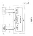
- FIG. 1is a schematic block diagram of a single battery charger having an integrated circuit package charger logic and control according to an embodiment of the invention
- FIG. 2is a schematic block diagram of the charger logic and control embodiment of FIG. 1;
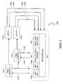
- FIG. 3is a schematic block diagram of a dual battery charger having an integrated circuit package charger logic and control according to another embodiment of the invention.
- FIG. 4is a schematic block diagram of the charger logic and control embodiment of FIG. 3;
- FIG. 5is a schematic block diagram of a dual battery charger having an integrated circuit package charger logic and control according to yet another embodiment of the invention.
- FIG. 6is a schematic block diagram of the charger logic and control embodiment of FIG. 5;
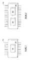
- FIG. 7is a schematic plan view of a single die integrated circuit package, according to an embodiment of the invention.
- FIG. 8is a schematic plan view of a dual die integrated circuit package, according to an embodiment of the invention.
- the inventionis a battery charger logic and control comprising a microcontroller, a switch mode power supply (SMPS) controller(s), an analog-to-digital converter (ADC) and an analog input multiplexer fabricated on an integrated circuit die which is contained in a single integrated circuit package.
- SMPSswitch mode power supply
- ADCanalog-to-digital converter
- Another embodimentcomprises the aforementioned functions fabricated on two integrated circuit dice interconnected in a single integrated circuit package.
- Still another embodimentcomprises the aforementioned embodiments including a power converter on a third power transistor die or on the same die as the SMPS controller, all connected together within an integrated circuit package.
- the inventionis used in conjunction with the power converter for charging a battery or a plurality of batteries.
- the inventionis especially advantageous for easily implementing a battery charger design and reducing the component count thereof.
- the integrated circuit package charger logic and controlis generally represented by the numeral 100 and comprises a microcontroller 102 , a switch mode power supply (SMPS) controller 104 , an analog-to-digital converter (ADC) 106 , and an analog input multiplexer 108 .
- a power converter 110converts a power source (not illustrated) such as AC mains or a larger battery system such as found in an automobile to a voltage and current appropriate for charging a battery 112 .
- the SMPS controller 104 of the charger logic and control 100controls the power converter 110 and monitors battery 112 current and/or voltage during charging thereof.
- the SMPS controller 104has an output 114 which may have a repetition of on/off pulses used to drive the power transistor circuits (not illustrated) of the power converter 110 , and inputs 116 which monitor the current and voltage being applied to the battery 112 .
- the series of on/off pulses on the output 114may be, for example but not limitation, pulse width, pulse position, or pulse skipping modulation.
- Analog inputs 118 from the battery 112are received by the analog input multiplexer 108 which multiplexes each signal on the inputs 118 to the input of the ADC 106 .
- the ADC 106converts each of the analog signals on the inputs 118 into a digital representation for use by the microcontroller 102 .
- the analog inputs 118are condition values from the battery 112 being charged and comprise, for example but not limitation, charging voltage and current, temperature, etc., of the battery 112 .
- the microcontroller 102may also read a digital battery identification value 120 so that an appropriate charging algorithm may be selected for the respective battery 112 being charged.
- This battery identification valuemay be coded into the case of the battery 112 , and when this case is connected to the battery charger illustrated in FIG. 1, the battery type code is also connected to the microprocessor 102 . Also contemplated and within the scope of the invention are digital battery status inputs, e.g., switched inputs that may represent high temperature, high pressure, low electrolyte, etc., of the battery 112 .
- the microcontroller 102is programmed with a charging algorithm for each type of battery 112 that can be charged in the battery charger.
- the program of the microcontroller 102causes a voltage setpoint and/or a current setpoint to be sent to the SMPS controller 104 .
- the SMPS controller 104uses the setpoint(s) as a target reference(s) when comparing current and voltage inputs 116 (parameter signals) from the power converter 110 .
- the SMPS controller 104has a pulsed output 114 which drives the power transistors in the power converter 110 .
- the SMPS controller 104For a closed loop charger system, when the current and/or voltage inputs 116 are less than the setpoint(s) from the microprocessor 102 , the SMPS controller 104 increases the pulse repetition rate and/or duty cycle at the output 114 which causes the power converter 110 to correspondingly increase the associated voltage and/or current to the battery 112 being charged. On the other hand, when the current and/or voltage inputs 116 are greater than the setpoint(s) from the microprocessor 102 , the SMPS controller 104 decreases the pulse repetition rate and/or duty cycle at the output 114 which causes the power converter 110 to correspondingly decrease the associated voltage and/or current to the battery 112 being charged. Thus when the SMPS controller 104 functions as a closed loop controller, it attempts to maintain the charging voltage and/or current of the battery 112 within a close approximation of the voltage and/or current setpoints generated by the microcontroller 102 .
- the microcontroller 102While the SMPS controller 102 preferably functions as an analog closed loop controller to maintain the voltage and/or current charging rates to the battery 112 in accordance with the setpoint(s), the microcontroller 102 also monitors condition values of the battery 112 being charged. These condition values are received at the analog inputs 118 and may be, for example but not limitation, charging voltage and current, temperature, etc. Digital values (high/low logic levels, switch contacts and the like) may be received at input(s) 120 for use by the microcontroller 102 . Typical digital values at input 120 may be battery identification codes, presence of a battery to be charged, high temperature, low water or electrolyte level, high pressure and the like.
- FIG. 3a schematic block diagram of a dual battery charger having an integrated circuit package charger logic and control according to another embodiment of the invention is illustrated.
- the integrated circuit package dual charger logic and controlis generally represented by the numeral 300 and comprises a microcontroller 102 , a switch mode power supply (SMPS) controller 104 , an analog-to-digital converter (ADC) 106 , and an analog input multiplexer 108 .
- a power converter 110converts a power source (not illustrated) such as AC mains or a larger battery system such as found in an automobile to a voltage and current appropriate for charging batteries 312 a and 312 b.
- a power transfer switch 322is used for switching the output of the power converter 110 to one of the two batteries 312 a and 312 b being charged. The power transfer switch 322 is controlled by the microcontroller 102 through output 324 .
- the SMPS controller 104 of the charger logic and control 300controls the power converter 110 and monitors the selected battery current and/or voltage during charging thereof. Since the output of the power converter 110 is switched between the batteries 312 a and 312 b by the power transfer switch 322 , the current and/or voltage monitored also changes. The charging priority and duration for each of the batteries 312 a and 312 b may be controlled by the microcontroller 102 .
- the SMPS controller 104has an output 114 which may be a repetition of on/off pulses used to drive the power transistor circuits (not illustrated) of the power converter 110 , and inputs 116 which monitor the current and voltage being applied to the selected battery 312 a or 312 b.
- the signal on the output 114is a series of on/off pulses which may be, for example but not limitation, pulse width, pulse position, or pulse skipping modulation.
- Analog inputs 318 a and 318 b from the battery 312 a and 312 b, respectively,are received by the analog input multiplexer 108 which multiplexes each signal on the inputs 318 to the input of the ADC 106 .
- the ADC 106converts each of the analog signals on the inputs 318 into digital representations for use by the microcontroller 102 .
- the analog inputs 318 a and 318 bare condition values from the batteries 312 a and 312 b, respectively, and comprise, for example but not limitation, charging voltage and current, charged voltage, temperature, etc.
- the microcontroller 102may also read digital battery identification values 320 a and 320 b so that appropriate charging algorithms may be selected for the respective batteries 312 a and 312 b being charged.
- the batteries 312 a and 312 bare not required to be the same capacity, voltage or chemistry type.
- These battery identification valuesmay be coded into the cases of the batteries 312 a and 312 b, and when these cases are connected to the battery charger illustrated in FIG. 3, the battery type codes are also connected to the microprocessor 102 .
- digital battery status inputse.g., switched inputs that may represent high temperature, high pressure, low electrolyte, etc., of the batteries 312 a and 312 b.
- the microcontroller 102is programmed with a charging algorithm for each type of battery 312 that can be charged in the battery charger.
- the program of the microcontroller 102causes a voltage setpoint and/or a current setpoint to be sent to the SMPS controller 104 .
- the SMPS controller 104uses the setpoint(s) as a target reference(s) when comparing current and voltage inputs 116 (parameter signals) from the power converter 110 .
- the SMPS controller 104has a pulsed output 114 which drives the power transistors in the power converter 110 .
- the SMPS controller 104For a closed loop charger system, when the current and/or voltage inputs 116 are less than the setpoint(s) from the microprocessor 102 , the SMPS controller 104 increases the pulse repetition rate and/or duty cycle at the output 114 which causes the power converter 110 to correspondingly increase the associated voltage and/or current to the battery 312 being charged. On the other hand, when the current and/or voltage inputs 116 are greater than the setpoint(s) from the microprocessor 102 , the SMPS controller 104 decreases the pulse repetition rate and/or duty cycle at the output 114 which causes the power converter 110 to correspondingly decrease the associated voltage and/or current to the battery 312 being charged. Thus when the SMPS controller 104 functions as a closed loop controller, it attempts to maintain the charging voltage and/or current of the battery 312 within a close approximation of the voltage and/or current setpoints generated by the microcontroller 102 .
- the microcontroller 102While the SMPS controller 104 preferably functions as an analog closed loop controller to maintain the voltage and/or current charging rates to the selected battery 312 in accordance with the setpoint(s), the microcontroller 102 also can monitor condition values of both batteries 312 a and 312 b. These condition values are received at the analog inputs 318 and may be, for example but not limitation, charging voltage and current, temperature, etc. Digital values (high/low logic levels, switch contacts and the like) may be received at inputs 320 for use by the microcontroller 102 . Typical digital values at inputs 320 a and 320 b may be battery identification codes, presence of a battery to be charged, high temperature, low water or electrolyte level, high pressure and the like.
- FIG. 5a schematic block diagram of a simultaneous dual battery charger having an integrated circuit package charger logic and control according to yet another embodiment of the invention is illustrated.
- the integrated circuit package simultaneous dual charger logic and controlis generally represented by the numeral 500 and comprises a microcontroller 102 , two switch mode power supply (SMPS) controllers 504 a and 504 b, an analog-to-digital converter (ADC) 106 , and an analog input multiplexer 108 .
- Two power converters 510 a and 510 bconvert a power source (not illustrated) such as AC mains or a larger battery system such as found in an automobile to a voltage and current appropriate for simultaneously charging batteries 512 a and 512 b. Charging of more than two batteries is also contemplated and within the spirit and intent of the invention.
- An individual SMPS and power converter for each batteryis contemplated and with the scope of the invention.
- the SMPS controllers 504 a and 504 bcontrol the power converters 510 a and 510 b, respectively, and monitor the battery current and/or voltage during charging thereof.
- the SMPS controllers 504 a and 504 bhave outputs 514 a and 514 b, respectively, each having a repetition of on/off pulses used to drive the power transistor circuits (not illustrated) of the power converters 510 a and 510 b, respectively, and inputs 516 a and 516 b which monitor the current and voltage being applied to the batteries 512 a and 512 b, respectively.
- the signals on the outputs 514 a and 514 bare a series of on/off pulses which may be, for example but not limitation, pulse width, pulse position, or pulse skipping modulation.
- Analog inputs 518 a and 518 b from the batteries 512 a and 512 b, respectively,are received by the analog input multiplexer 108 which multiplexes each signal on the inputs 518 to the input of the ADC 106 .
- the ADC 106converts each of the analog signals on the inputs 518 into digital representations for use by the microcontroller 102 .
- the analog inputs 518 a and 518 bare condition values from the batteries 512 a and 512 b, respectively, and comprise, for example but not limitation, charging voltage and current, charged voltage, temperature, etc.
- the microcontroller 102may also read digital battery identification values 520 a and 520 b (FIG.
- the batteries 512 a and 512 bare not required to be the same capacity, voltage or chemistry type. These battery identification values may be coded into the cases of the batteries 512 a and 512 b, and when these cases are connected to the battery charger illustrated in FIG. 5, the battery type codes are also connected to the microprocessor 102 . Also contemplated and within the scope of the invention are digital battery status inputs, e.g., switched inputs that may represent high temperature, high pressure, low electrolyte, etc., of the batteries 512 a and 512 b.
- the microcontroller 102is programmed with a charging algorithm for each type of battery 512 that can be charged in the battery charger.
- the program of the microcontroller 102causes a voltage setpoint and/or a current setpoint to be sent to the SMPS controllers 504 a and 504 b.
- the SMPS controllers 504 a and 504 buse the setpoints as target references when comparing current and voltage inputs 516 a and 516 b (parameter signals) from the power converters 510 a and 510 b.
- the SMPS controllers 504 a and 504 bhave pulsed outputs 514 a and 514 b, respectively, which drive the power transistors in the power converters 510 a and 510 b.
- the SMPS controllers 502 a and 502 bpreferably function as analog closed loop controllers to maintain the voltage and/or current charging rates to the respective batteries 512 a and 512 b in accordance with the respective setpoints.
- the microcontroller 102also can monitor condition values of the batteries 512 a and 512 b. These condition values are received at the analog inputs 518 a and 518 b and may be, for example but not limitation, charging voltage and current, temperature, etc. Digital values (high/low logic levels, switch contacts and the like) may be received at inputs 520 a and 520 b for use by the microcontroller 102 . Typical digital values at inputs 520 a and 520 b may be battery identification codes, presence of a battery to be charged, high temperature, low water or electrolyte level, high pressure and the like.
- the power converter(s)may be integrated with the SMPS controller(s) or the power converter(s) may be fabricated on its own semiconductor die and connected thereto in a single integrated circuit package.
- the ADC 106 in combination with the analog input multiplexer 108has a plurality of analog inputs, and preferably produces a 10 bit analog to digital conversion resolution.
- a START bitmay be set (Analog Conv. of FIG. 2) to start a conversion of the ADC 106 .
- the microcontroller 102also controls the input selection of the input multiplexer 108 .
- the microcontroller 102 programcan poll the ADC 106 to determine when it is finished converting the analog signal. When conversion is done, the ADC 106 will clear the START bit. It is also contemplated and within the scope of the invention that the ADC 106 may be setup to produce an interrupt once conversion is done.
- the voltage reference for the ADC 106may be selected from an internal voltage reference module, or from an external voltage reference (not illustrated).
- any type of ADC that can be fabricated on an integrated circuitmay be used for the ADC 106 .
- the analog signal range to be measureddoes not necessarily match the ADC 106 input range.
- an op-amp circuitmay be required to offset the signal and introduce the necessary gain, so that the ADC 106 may be used within its maximum input range.
- the ADC 106 of the inventionaddresses this need by allowing the designer to match the ADC voltage measurement window to the range of the measured analog signal. This may be done by component selection for the ADC channels of interest, without the need of any external op-amps.
- a nickel cadmium battery chargerrequires the detection and measurement of a very small battery voltage slope reversal ( ⁇ dV/dT) in order to determine whether a full charge condition has been reached.
- ⁇ dV/dTbattery voltage slope reversal
- the SMPS controller 104is adapted to drive the power converter 110 which, preferably, may be an external switch mode power supply circuit.
- the SMPS controller 104uses either one or two feedback inputs, depending on the control mode selected. These two feedback inputs are current feedback and/or voltage feedback.
- the SMPS controller 104preferably supports three modes: 1) constant voltage (CV), 2) constant current (CC), and 3) constant voltage with current compliance (CVCC).
- the SMPS controller 104In the CV mode, the SMPS controller 104 only requires a voltage feedback (VFB) at input 116 for control.
- the output 114will generate pulses to drive the power converter 110 so that it maintains a constant voltage representation at the input 116 .
- Voltage setpoint valuesmay be selected by the program or firmware in the microcontroller 102 .
- the SMPS controller 104In the CC mode, the SMPS controller 104 only requires current feedback (IFB) at input 116 for control.
- IFBcurrent feedback
- the output 114will generate pulses to drive the power converter 110 so that it maintains a constant current representation at the input 116 (a voltage is generated across a low resistance in series with the battery charging current).
- Current setpoint valuesmay be selected by the program or firmware in the microcontroller 102 .
- the SMPS controller 104In the CVCC mode, the SMPS controller 104 requires both voltage (VFB) and current (IFB) feedback at the inputs 116 for control. The SMPS controller 104 will control in the CV mode as long as the current does not exceed the current setpoint If the current reaches the current setpoint, then the CC mode will take over. Both voltage and current setpoints are provided internally, and may be individually set by the program or firmware in the microcontroller 102 .
- the output 114 of the SMPS controller 110can be configured to drive a power converter 110 having either buck or boost topologies, or to close the control loop when an external off-line switcher is used.
- the SMPS controller 104 outputgenerates pulses adapted to drive the power converter 110 so that the controlled battery voltage or current matches the setpoint(s) from the microcontroller 102 .
- the switching frequency of the outputmay be derived from the microcontroller 102 main oscillator. Using a 4 MHz internal oscillator mode, the switching frequency can be set, for example but not limitation, to 62.5 kHz, 125 kHz, or 250 kHz.
- the duty cycle of this output waveformpreferably may be selected between 25%, 50%, 75%, and 93%. However, any duty cycle may be utilized depending on the application. Optimization of the frequency and duty cycle may be determined by the power device sizes, losses, and costs of the power switcher.
- the output 114When the output 114 is configured for an external off-line switcher mode, the output 114 functions as a control error indicator. When either the battery voltage or current reaches the corresponding setpoint, the output 114 will go low. This output 114 signal can then be used to signal the external off-line switcher to slow down power conversion.
- the closed loop systemthen, is operating as a CV, CC, or CVCC regulator based on the selected control mode.
- a voltage reference module(not illustrated) may use the supply voltage which powers the charger logic and control 100 or an external voltage reference source may be utilized.
- the ADC 106preferably uses a voltage reference module output for its operation.
- Examples of which the invention is particularly well suited forare applications that involve voltage and (or) current regulation, as well as high resolution measurements for monitoring and control purposes. Some of those applications are battery chargers, un-interruptible power supply (UPS), power supplies, CO detectors, etc. Power management of the input power during charging of a plurality of batteries is contemplated and within the scope of the invention.
- a substantially discharged batterycan pull a high charging current and charging a number of discharged batteries can place a heavy instantaneous (on startup) and continuous load on the primary power source.
- the inventioncan regulate the amount of primary power drawn from the power source by controlling the amount of charging voltage and/or current applied to the batteries being charged.
- Examples of battery charger applicationsare as follows: For Nicad and NiMH batteries, in smart battery chargers, depending on the battery chemistry, either a current source or a voltage source is required to charge the battery. For both Nicad and NiMH batteries, the charger normally provides a constant current. When charging begins, the charger supplies a high current to the battery. During this time, the charger is monitoring either (or both) the battery voltage, or (and) the battery temperature as a critical parameter to determine when the battery reaches a full charge condition. Once the fill charge condition is detected, the charger drops the charging current to a much lower value, called a trickle current.
- This trickle currentis continuously applied to top off the battery to keep it at full charge until the battery is removed from the charger or until the charger power is removed.
- This exampleis just one of the commonly used methods.
- Charger designtypically follows the charging algorithms for the batteries to be charged, which are normally specified by the battery manufacturer.
- the SMPS controller 110may control an external buck or boost power circuit with a current feedback.
- An internal amplifier(not illustrated) can directly amplify the external current sense resistor voltage, so an external op-amp circuit is not required to sense the charging current.
- the charging currentis converted to voltage, it is controlled to track the internal programmable current set point reference.
- the firmware of the microcontroller 102need only set the control mode to CC (Constant Current), and set the set-point to select the charging and trickle current values. This makes the design of the charging current source circuit very easy and with a minimum number of external components.
- an off-line switchermay be used for efficiency reasons, or to meet universal input voltage requirements.
- the SMPS controller 104may be configured to produce an output that can be used as a feedback to the external off-line switching supply controller. In this mode, the SMPS controller 104 output will produce a low signal, if either the battery voltage or current reaches the desired set point.
- an opto-couplerpreferably may be used to maintain circuit isolation. With a current limiting resistor in place, the SMPS controller 104 output can directly drive the opto-coupler's LED.
- the charger control circuitsIn the case of a Nicad battery, the charger control circuits must be able to measure a small drop in the battery voltage to detect a fill charge condition. In some charger designs, a voltage drop as small as 30 mV must be measured on top of a 7.2 V battery voltage. First of all, this voltage more than likely is outside the input range of commercially available A/D converters (e.g., 0 to 5 V). Secondly, the 30 mV change is just barely above the least significant bit change of an 8 bit ADC, if the input range of the ADC is 7.2 V. Therefore, most of the available low cost AID converters in the market will require the use of an op-amp to introduce an offset and gain so as to bring the battery voltage of interest within the ADC's measurement range and resolution.
- the ADC 106 of the inventionis capable of making high-resolution measurements easily.
- the ADC 106may scale its input range for a full 10 bits of resolution, thus for a Nicad battery, the ADC 106 input range may be set to a 6 to 9 volt range. This gives the microcontroller 102 a 2.9 mV measurement resolution.
- the scaling of the ADC 106 input rangemay preferably be done by the proper selection of resistor values.
- the ADC 106may measure the resistance value of a thermistor commonly used to measure battery temperatures.
- the measurement rangeis defined by selecting the proper resistor values, depending on the thermistor's resistance value.
- Lithium Ion batterieshave different charging requirements than either Nicad or NiMH.
- the chargerWhen charging begins, the charger must supply a constant current to the battery. In the mean time, the battery voltage is increasing toward its maximum voltage (i.e.: 4.1 V or 4.2 V for a single Li-ion cell, depending on the Li-ion type, specified by the manufacturer). Once the battery voltage reaches its maximum voltage, the charger must change the charging mode to a constant voltage source. The charging current will now decrease over time as the battery continues to charge. Eventually, the current will reach a small threshold value, i.e., 25 ma (normally specified by the battery manufacturer), at which point the battery is fully charged. In some cases, some battery manufacturers may say that after this current threshold is reached, charging in constant voltage mode may continue for an additional fixed amount of time to fully top off the battery. Once the battery is fully charged, the charger must completely turn off the charging current.
- a small threshold valuei.e. 25 ma (normally specified by the battery manufacturer)
- Li-Ion battery charger designspreferably will include a precision voltage reference, or a calibration step to make sure that the charging voltage is within the battery manufacturer's specifications.
- the SMPS controller 104uses the CVCC (constant voltage with current compliance) mode to control in either the constant voltage or constant current mode.
- CVCCconstant voltage with current compliance
- the constant current modeis active. Once the battery voltage reaches its maximum voltage, the constant voltage mode will automatically take over, allowing the charging current to decrease. This feature simplifies the charger's firmware algorithm, since the SMPS controller 104 automatically takes care of the most critical step in the Li-ion battery charging process.
- the constant voltage moderequires a voltage feedback from the battery.
- a simple voltage divider resistor circuitmay be used to provide this voltage feedback.
- a stable and accurate power supply, or an external voltage referenceis needed.
- a calibration stepmay not be necessary.
- a highly accurate voltage referencemay be available or a small trimpot may be placed in the divider circuit to adjust the reference voltage during the calibration stage.
- the SMPS controller 104may be configured to suit the requirements of the charging algorithm.
- the ADC 106can be used to read the battery voltage (i.e.: 12 V, 24 V, etc.) by properly choosing the correct resistor values for the required voltage measurement window.
- An integrated circuit package represented by the numeral 700comprises a single die 704 and leadframe connections 702 .
- the die 704may be connected to the leadframe 702 with or without encapsulation thereover, a printed wiring board (PWB) or substrate (not illustrated) by wire bonding, tape automated bonding, C4 and the like.
- PWBprinted wiring board
- Typical integrated circuit packagesare for example but not limitation: Plastic Dual In-line Package (PDIP), Small Outline (SO), Shrink Small Outline Package (SSOP), Thin Shrink Small Outline Package (TSSOP), windowed Ceramic Dual In-line Package (CERDIP), Leadless Chip Carrier (LCC), Plastic Leaded Chip Carrier (PLCC), Plastic Quad Flatpack Package (PQFP), Thin Quad Flatpack Package (TQFP), Pin Grid Array (PGA), Ball Grid Array (BGA), TO- 220 , T 0 - 247 and T 0 - 263 (power surface mount package), or the die may remain unencapsulated on a tape film leadframe carrier, or as an unpackaged “flip-chip.”
- PDIPPlastic Dual In-line Package
- SOSmall Outline
- SSOPShrink Small Outline Package
- TSSOPThin Shrink Small Outline Package
- CERDIPwindowed Ceramic Dual In-line Package
- LCCLeadless Chip Carrier
- PLCCPlastic Leaded Chip Carrier
- a first die 804 and a second die 806may be connected together within an integrated circuit package 800 by wire bonding, ball bump bonding, flipchip, C4 and the like.
- I/O connectionsmay be provided through a leadframe, integrated circuit package pins (PGA) or solder ball connections (BGA).
Landscapes
- Engineering & Computer Science (AREA)
- Power Engineering (AREA)
- Charge And Discharge Circuits For Batteries Or The Like (AREA)
- Control Of Voltage And Current In General (AREA)
Abstract
Description
Claims (29)
Priority Applications (1)
| Application Number | Priority Date | Filing Date | Title |
|---|---|---|---|
| US09/773,439US6456044B1 (en) | 1999-02-16 | 2001-01-31 | Microcontroller with integral switch mode power supply controller |
Applications Claiming Priority (2)
| Application Number | Priority Date | Filing Date | Title |
|---|---|---|---|
| US09/250,756US6184659B1 (en) | 1999-02-16 | 1999-02-16 | Microcontroller with integral switch mode power supply controller |
| US09/773,439US6456044B1 (en) | 1999-02-16 | 2001-01-31 | Microcontroller with integral switch mode power supply controller |
Related Parent Applications (1)
| Application Number | Title | Priority Date | Filing Date |
|---|---|---|---|
| US09/250,756Continuation-In-PartUS6184659B1 (en) | 1999-02-16 | 1999-02-16 | Microcontroller with integral switch mode power supply controller |
Publications (1)
| Publication Number | Publication Date |
|---|---|
| US6456044B1true US6456044B1 (en) | 2002-09-24 |
Family
ID=22949009
Family Applications (2)
| Application Number | Title | Priority Date | Filing Date |
|---|---|---|---|
| US09/250,756Expired - LifetimeUS6184659B1 (en) | 1999-02-16 | 1999-02-16 | Microcontroller with integral switch mode power supply controller |
| US09/773,439Expired - LifetimeUS6456044B1 (en) | 1999-02-16 | 2001-01-31 | Microcontroller with integral switch mode power supply controller |
Family Applications Before (1)
| Application Number | Title | Priority Date | Filing Date |
|---|---|---|---|
| US09/250,756Expired - LifetimeUS6184659B1 (en) | 1999-02-16 | 1999-02-16 | Microcontroller with integral switch mode power supply controller |
Country Status (6)
| Country | Link |
|---|---|
| US (2) | US6184659B1 (en) |
| EP (1) | EP1072078A1 (en) |
| JP (1) | JP2002537753A (en) |
| KR (1) | KR20010042769A (en) |
| CN (1) | CN1240170C (en) |
| WO (1) | WO2000049699A1 (en) |
Cited By (53)
| Publication number | Priority date | Publication date | Assignee | Title |
|---|---|---|---|---|
| US20040130288A1 (en)* | 2002-09-12 | 2004-07-08 | Souther James P. | Isolated high voltage battery charger and integrated battery pack |
| US20040164711A1 (en)* | 2003-02-25 | 2004-08-26 | Isao Hayashi | Battery charger and method therefor |
| US20050200332A1 (en)* | 2004-03-11 | 2005-09-15 | International Business Machines Corporation | Intelligent multiple battery charging station |
| US20050253554A1 (en)* | 2004-05-14 | 2005-11-17 | Interdigital Technology Corporation | Apparatus for backing up data stored in a portable device |
| US20060010763A1 (en)* | 2004-07-13 | 2006-01-19 | Bikini Lures, Inc. | Electronic fishing lure |
| US20060071634A1 (en)* | 2002-11-22 | 2006-04-06 | Meyer Gary D | Method and system for battery charging |
| US20060108983A1 (en)* | 2002-11-22 | 2006-05-25 | Milwaukee Electric Tool Corporation. | Method and system for battery charging |
| US20060186858A1 (en)* | 2005-02-18 | 2006-08-24 | Advanced Connection Technology Inc. | Charging apparatus |
| US7202651B2 (en) | 2002-11-19 | 2007-04-10 | Power-One, Inc. | System and method for providing digital pulse width modulation |
| US7239115B2 (en) | 2005-04-04 | 2007-07-03 | Power-One, Inc. | Digital pulse width modulation controller with preset filter coefficients |
| US20070165345A1 (en)* | 2006-01-17 | 2007-07-19 | Broadcom Corporation | Power over Ethernet electrostatic discharge protection circuit |
| US7249267B2 (en) | 2002-12-21 | 2007-07-24 | Power-One, Inc. | Method and system for communicating filter compensation coefficients for a digital power control system |
| US7266709B2 (en) | 2002-12-21 | 2007-09-04 | Power-One, Inc. | Method and system for controlling an array of point-of-load regulators and auxiliary devices |
| US20070270183A1 (en)* | 2006-05-22 | 2007-11-22 | Tredwell Robin L | Light emitting mobile communication device and charger therefor |
| US7315156B2 (en) | 2003-03-14 | 2008-01-01 | Power-One, Inc. | System and method for controlling output-timing parameters of power converters |
| US7315157B2 (en) | 2003-02-10 | 2008-01-01 | Power-One, Inc. | ADC transfer function providing improved dynamic regulation in a switched mode power supply |
| US7327149B2 (en) | 2005-05-10 | 2008-02-05 | Power-One, Inc. | Bi-directional MOS current sense circuit |
| US7372682B2 (en) | 2004-02-12 | 2008-05-13 | Power-One, Inc. | System and method for managing fault in a power system |
| US7373527B2 (en) | 2002-12-23 | 2008-05-13 | Power-One, Inc. | System and method for interleaving point-of-load regulators |
| US20080136377A1 (en)* | 2006-12-08 | 2008-06-12 | Monolithic Power Systems, Inc. | Battery charger with temperature control |
| US7394445B2 (en) | 2002-11-12 | 2008-07-01 | Power-One, Inc. | Digital power manager for controlling and monitoring an array of point-of-load regulators |
| US7394236B2 (en) | 2005-03-18 | 2008-07-01 | Power-One, Inc. | Digital double-loop output voltage regulation |
| US20080171402A1 (en)* | 2002-10-08 | 2008-07-17 | Marcos Karnezos | Method of fabricating a semiconductor multi-package module having inverted land grid array (lga) package stacked over ball grid array (bga) package |
| US20080265984A1 (en)* | 2006-08-31 | 2008-10-30 | Ami Semiconductor Belgium Bvba | Over-voltage protection for power and data applications |
| US7456617B2 (en) | 2002-11-13 | 2008-11-25 | Power-One, Inc. | System for controlling and monitoring an array of point-of-load regulators by a host |
| US7459892B2 (en) | 2002-11-12 | 2008-12-02 | Power-One, Inc. | System and method for controlling a point-of-load regulator |
| US20090027863A1 (en)* | 2003-04-04 | 2009-01-29 | Marcos Karnezos | Method for making a semiconductor multipackage module including a processor and memory package assemblies |
| US7526660B2 (en) | 2003-03-14 | 2009-04-28 | Power-One, Inc. | Voltage set point control scheme |
| US7528579B2 (en) | 2003-10-23 | 2009-05-05 | Schumacher Electric Corporation | System and method for charging batteries |
| US20090161281A1 (en)* | 2007-12-21 | 2009-06-25 | Broadcom Corporation | Capacitor sharing surge protection circuit |
| US7554310B2 (en) | 2005-03-18 | 2009-06-30 | Power-One, Inc. | Digital double-loop output voltage regulation |
| US7673157B2 (en) | 2002-12-21 | 2010-03-02 | Power-One, Inc. | Method and system for controlling a mixed array of point-of-load regulators through a bus translator |
| US7710092B2 (en) | 2003-02-10 | 2010-05-04 | Power-One, Inc. | Self tracking ADC for digital power supply control systems |
| CN101093942B (en)* | 2003-02-25 | 2010-06-02 | 佳能株式会社 | Battery charger and method therefor |
| US7737961B2 (en) | 2002-12-21 | 2010-06-15 | Power-One, Inc. | Method and system for controlling and monitoring an array of point-of-load regulators |
| US7743266B2 (en) | 2002-12-21 | 2010-06-22 | Power-One, Inc. | Method and system for optimizing filter compensation coefficients for a digital power control system |
| US7836322B2 (en) | 2002-12-21 | 2010-11-16 | Power-One, Inc. | System for controlling an array of point-of-load regulators and auxiliary devices |
| US7834613B2 (en) | 2007-10-30 | 2010-11-16 | Power-One, Inc. | Isolated current to voltage, voltage to voltage converter |
| US7882372B2 (en) | 2002-12-21 | 2011-02-01 | Power-One, Inc. | Method and system for controlling and monitoring an array of point-of-load regulators |
| US20110068040A1 (en)* | 2004-01-29 | 2011-03-24 | E.I. Du Pont De Nemours And Company | Compositions of ethylene/vinyl acetate copolymers for heat-sealable easy opening packaging |
| US7944181B2 (en) | 2002-11-22 | 2011-05-17 | Milwaukee Electric Tool Corporation | Battery pack |
| US8120363B2 (en) | 2008-11-24 | 2012-02-21 | Cummins Power Generation Ip, Inc. | Voltage drop compensation for an electric power storage device charging system |
| EP2466718A1 (en) | 2010-12-16 | 2012-06-20 | Dialog Semiconductor GmbH | Multiple battery charger with automatic charge current adjustment |
| US8471532B2 (en) | 2002-11-22 | 2013-06-25 | Milwaukee Electric Tool Corporation | Battery pack |
| WO2014179005A1 (en)* | 2013-05-01 | 2014-11-06 | Apple Inc. | Battery charger integrated circuit chip |
| US9735665B2 (en) | 2009-07-31 | 2017-08-15 | Power Integrations, Inc. | Method and apparatus for implementing a power converter input terminal voltage discharge circuit |
| US10069319B2 (en) | 2016-03-08 | 2018-09-04 | Apple Inc. | Systems and methods for simultaneously charging a battery with multiple power sources |
| US10193435B2 (en) | 2009-06-03 | 2019-01-29 | Semiconductor Components Industries, Llc | Start-up circuit to discharge EMI filter for power saving of power supplies |
| US10211733B1 (en)* | 2016-06-16 | 2019-02-19 | Google Llc | DC-DC converter |
| US20200067315A1 (en)* | 2016-11-09 | 2020-02-27 | Samsung Sdi Co., Ltd. | Energy storage apparatus |
| US10593991B2 (en) | 2002-11-22 | 2020-03-17 | Milwaukee Electric Tool Corporation | Method and system for battery protection |
| US20220181897A1 (en)* | 2020-12-04 | 2022-06-09 | Schneider Electric It Corporation | Method to enhance the life of a lithium battery |
| CN118677072A (en)* | 2024-08-22 | 2024-09-20 | 深圳通业科技股份有限公司 | Charging system, charging control method, terminal and medium |
Families Citing this family (37)
| Publication number | Priority date | Publication date | Assignee | Title |
|---|---|---|---|---|
| US6184659B1 (en)* | 1999-02-16 | 2001-02-06 | Microchip Technology Incorporated | Microcontroller with integral switch mode power supply controller |
| JP3212963B2 (en)* | 1999-03-16 | 2001-09-25 | 松下電器産業株式会社 | Secondary battery control circuit |
| US6515464B1 (en)* | 2000-09-29 | 2003-02-04 | Microchip Technology Incorporated | Input voltage offset calibration of an analog device using a microcontroller |
| US6879059B2 (en)* | 2001-07-05 | 2005-04-12 | Sleva Associates, Inc. | Interruptible power supply module |
| US6621248B1 (en)* | 2002-03-13 | 2003-09-16 | Advanced-Connectek Inc. | Charging device with selectable output voltage values |
| US7253585B2 (en) | 2002-11-22 | 2007-08-07 | Milwaukee Electric Tool Corporation | Battery pack |
| US7714538B2 (en) | 2002-11-22 | 2010-05-11 | Milwaukee Electric Tool Corporation | Battery pack |
| DE10362316B4 (en)* | 2002-11-22 | 2021-05-27 | Milwaukee Electric Tool Corp. | System for charging a battery |
| KR100500452B1 (en)* | 2003-06-20 | 2005-07-12 | 삼성전자주식회사 | Ball Grid Array Package Test Apparatus and Method |
| US7091697B2 (en)* | 2003-11-04 | 2006-08-15 | Sony Corporation | System and method for efficiently implementing a battery controller for an electronic device |
| USD558670S1 (en) | 2006-01-09 | 2008-01-01 | Milwaukee Electric Tool Corporation | Battery |
| US8271816B2 (en)* | 2008-03-11 | 2012-09-18 | Infineon Technologies Austria Ag | System and method for statistics recording of power devices |
| US8076797B2 (en)* | 2008-05-15 | 2011-12-13 | Indy Power Systems Llc | Energy transfer circuit and method |
| US8143862B2 (en)* | 2009-03-12 | 2012-03-27 | 02Micro Inc. | Circuits and methods for battery charging |
| CN201690242U (en)* | 2009-12-03 | 2010-12-29 | 国基电子(上海)有限公司 | Double-mode charging circuit |
| WO2011109746A2 (en)* | 2010-03-05 | 2011-09-09 | University Of Central Florida Research Foundation, Inc. | Controllers for battery chargers and battery chargers therefrom |
| US8981710B2 (en) | 2010-09-20 | 2015-03-17 | Indy Power Systems Llc | Energy management system |
| WO2012136180A2 (en) | 2011-04-04 | 2012-10-11 | Schaeffler Technologies AG & Co. KG | Method for controlling a hybrid drivetrain and battery device in said hybrid drivetrain |
| CN102946243B (en)* | 2012-10-19 | 2015-01-21 | 陕西群力电工有限责任公司 | Ceramic lead-free relay tube shell |
| CN105073494B (en) | 2012-12-31 | 2017-04-12 | 冷王公司 | Transport refrigeration unit battery charging system and method of operating same |
| US10211488B2 (en)* | 2013-02-01 | 2019-02-19 | Husqvarna Ab | Battery pack interface system |
| US9812949B2 (en) | 2013-10-10 | 2017-11-07 | Indy Power Systems Llc | Poly-phase inverter with independent phase control |
| EP3087688B1 (en)* | 2013-12-26 | 2020-04-08 | Thermo King Corporation | Method and system for configuring a transport refrigeration unit battery charger for use in a transport refrigeration system |
| WO2015100397A1 (en) | 2013-12-26 | 2015-07-02 | Thermo King Corporation | Method and system for configuring a transport refrigeration unit battery charger for use in a transport refrigeration system |
| US9263898B1 (en)* | 2014-07-28 | 2016-02-16 | Ohanes D. Ghazarian | Dual battery charger mobile communication apparatus |
| US9525307B2 (en)* | 2014-07-28 | 2016-12-20 | Ohanes D. Ghazarian | Automatic dual battery charger mobile communication apparatus |
| TWI566499B (en)* | 2014-12-30 | 2017-01-11 | 仁寶電腦工業股份有限公司 | Charging method and charging device using the same |
| US9891646B2 (en)* | 2015-01-27 | 2018-02-13 | Qualcomm Incorporated | Capacitively-coupled hybrid parallel power supply |
| EP3068010A1 (en)* | 2015-03-10 | 2016-09-14 | HILTI Aktiengesellschaft | Battery charger and charging system that can be operated on mains power |
| CN104734292A (en)* | 2015-03-25 | 2015-06-24 | 深圳市安安森新能源实业有限公司 | Lead-acid storage battery charging maintenance device and system |
| US10170923B2 (en)* | 2016-01-12 | 2019-01-01 | Richtek Technology Corporation | Adaptive buck converter with monitor circuit and charging cable using the same |
| KR102010018B1 (en)* | 2016-02-24 | 2019-08-12 | 주식회사 엘지화학 | Electric box for battery pack and battery pack structure using thereof |
| DE102018108298A1 (en)* | 2018-04-09 | 2019-10-10 | Infineon Technologies Austria Ag | Controller for switching converter |
| CN110597152B (en)* | 2019-10-21 | 2024-04-30 | 航宇救生装备有限公司 | Strong-flash-preventing lens switch state self-adaptive control circuit based on microcontroller |
| WO2021217211A1 (en)* | 2020-05-01 | 2021-11-04 | Redarc Technologies Pty Ltd | Battery charging method and controller |
| US11871108B2 (en)* | 2020-09-15 | 2024-01-09 | Gopro, Inc. | Integrated internal and removable battery power management for image capture device |
| WO2025198636A1 (en)* | 2024-03-19 | 2025-09-25 | VLTRU Systems, LLC | Battery systems having pressure sensors and circuits for preventing battery fire and applications thereof |
Citations (4)
| Publication number | Priority date | Publication date | Assignee | Title |
|---|---|---|---|---|
| US5751139A (en)* | 1997-03-11 | 1998-05-12 | Unitrode Corporation | Multiplexing power converter |
| US5789903A (en)* | 1994-03-28 | 1998-08-04 | John York Seymour | Method and apparatus for processing batteries |
| US5945806A (en)* | 1997-08-29 | 1999-08-31 | Compaq Computer Corporation | Variable-voltage programmable battery module |
| US6184659B1 (en)* | 1999-02-16 | 2001-02-06 | Microchip Technology Incorporated | Microcontroller with integral switch mode power supply controller |
Family Cites Families (6)
| Publication number | Priority date | Publication date | Assignee | Title |
|---|---|---|---|---|
| US5523671A (en)* | 1991-02-14 | 1996-06-04 | Dell Usa, L.P. | Charging system for battery powered devices |
| JP3329858B2 (en)* | 1991-10-30 | 2002-09-30 | テキサス インスツルメンツ インコーポレイテツド | Battery system |
| US5284719A (en)* | 1992-07-08 | 1994-02-08 | Benchmarq Microelectronics, Inc. | Method and apparatus for monitoring battery capacity |
| IT1268472B1 (en)* | 1993-10-22 | 1997-03-04 | St Microelectronics Srl | BUCK CONVERTER WITH OPERATING MODE AUTOMATICALLY DETERMINED BY THE LOAD LEVEL |
| CA2169706A1 (en)* | 1995-03-03 | 1996-09-04 | Troy Lynn Stockstad | Circuit and method for battery charge control |
| US5774733A (en)* | 1995-10-03 | 1998-06-30 | Microchip Technology Incorporated | Microcontroller with analog front-end for providing intelligent battery management |
- 1999
- 1999-02-16USUS09/250,756patent/US6184659B1/ennot_activeExpired - Lifetime
- 2000
- 2000-02-15KRKR1020007011503Apatent/KR20010042769A/ennot_activeWithdrawn
- 2000-02-15JPJP2000600339Apatent/JP2002537753A/ennot_activeWithdrawn
- 2000-02-15CNCNB008004269Apatent/CN1240170C/ennot_activeExpired - Lifetime
- 2000-02-15WOPCT/US2000/003822patent/WO2000049699A1/ennot_activeApplication Discontinuation
- 2000-02-15EPEP00910182Apatent/EP1072078A1/ennot_activeCeased
- 2001
- 2001-01-31USUS09/773,439patent/US6456044B1/ennot_activeExpired - Lifetime
Patent Citations (4)
| Publication number | Priority date | Publication date | Assignee | Title |
|---|---|---|---|---|
| US5789903A (en)* | 1994-03-28 | 1998-08-04 | John York Seymour | Method and apparatus for processing batteries |
| US5751139A (en)* | 1997-03-11 | 1998-05-12 | Unitrode Corporation | Multiplexing power converter |
| US5945806A (en)* | 1997-08-29 | 1999-08-31 | Compaq Computer Corporation | Variable-voltage programmable battery module |
| US6184659B1 (en)* | 1999-02-16 | 2001-02-06 | Microchip Technology Incorporated | Microcontroller with integral switch mode power supply controller |
Cited By (124)
| Publication number | Priority date | Publication date | Assignee | Title |
|---|---|---|---|---|
| US20040130288A1 (en)* | 2002-09-12 | 2004-07-08 | Souther James P. | Isolated high voltage battery charger and integrated battery pack |
| US7253584B2 (en)* | 2002-09-12 | 2007-08-07 | General Motors Corporation | Isolated high voltage battery charger and integrated battery pack |
| US7687313B2 (en) | 2002-10-08 | 2010-03-30 | Stats Chippac Ltd. | Method of fabricating a semiconductor multi package module having an inverted package stacked over ball grid array (BGA) package |
| US20080171402A1 (en)* | 2002-10-08 | 2008-07-17 | Marcos Karnezos | Method of fabricating a semiconductor multi-package module having inverted land grid array (lga) package stacked over ball grid array (bga) package |
| US7459892B2 (en) | 2002-11-12 | 2008-12-02 | Power-One, Inc. | System and method for controlling a point-of-load regulator |
| US7394445B2 (en) | 2002-11-12 | 2008-07-01 | Power-One, Inc. | Digital power manager for controlling and monitoring an array of point-of-load regulators |
| US7782029B2 (en) | 2002-11-13 | 2010-08-24 | Power-One, Inc. | Method and system for controlling and monitoring an array of point-of-load regulators |
| US7456617B2 (en) | 2002-11-13 | 2008-11-25 | Power-One, Inc. | System for controlling and monitoring an array of point-of-load regulators by a host |
| US7202651B2 (en) | 2002-11-19 | 2007-04-10 | Power-One, Inc. | System and method for providing digital pulse width modulation |
| US9118189B2 (en) | 2002-11-22 | 2015-08-25 | Milwaukee Electric Tool Corporation | Method and system for charging multi-cell lithium-based battery packs |
| US20060071634A1 (en)* | 2002-11-22 | 2006-04-06 | Meyer Gary D | Method and system for battery charging |
| US20070103109A1 (en)* | 2002-11-22 | 2007-05-10 | Meyer Gary D | Method and system of charging multi-cell lithium-based batteries |
| US10714948B2 (en) | 2002-11-22 | 2020-07-14 | Milwaukee Electric Tool Corporation | Method and system for charging multi-cell lithium-based battery packs |
| US10593991B2 (en) | 2002-11-22 | 2020-03-17 | Milwaukee Electric Tool Corporation | Method and system for battery protection |
| US10536022B2 (en) | 2002-11-22 | 2020-01-14 | Milwaukee Electric Tool Corporation | Lithium-based battery pack for a hand held power tool |
| US11469608B2 (en) | 2002-11-22 | 2022-10-11 | Milwaukee Electric Tool Corporation | Lithium-based battery pack for a hand held power tool |
| US10374443B2 (en) | 2002-11-22 | 2019-08-06 | Milwaukee Electric Tool Corporation | Method and system for charging multi-cell lithium-based battery packs |
| US10097026B2 (en) | 2002-11-22 | 2018-10-09 | Milwaukee Electric Tool Corporation | Lithium-based battery pack for a hand held power tool |
| US10008864B2 (en) | 2002-11-22 | 2018-06-26 | Milwaukee Electric Tool Corporation | Method and system for charging multi-cell lithium-based battery packs |
| US10862327B2 (en) | 2002-11-22 | 2020-12-08 | Milwaukee Electric Tool Corporation | Lithium-based battery pack for a hand held power tool |
| US7262580B2 (en) | 2002-11-22 | 2007-08-28 | Milwaukee Electric Tool Corporation | Method and system for charging multi-cell lithium-based batteries |
| US7944181B2 (en) | 2002-11-22 | 2011-05-17 | Milwaukee Electric Tool Corporation | Battery pack |
| US9680325B2 (en) | 2002-11-22 | 2017-06-13 | Milwaukee Electric Tool Corporation | Lithium-based battery pack for a hand held power tool |
| US8018198B2 (en) | 2002-11-22 | 2011-09-13 | Milwaukee Electric Tool Corporation | Method and system for charging multi-cell lithium-based batteries |
| US9312721B2 (en) | 2002-11-22 | 2016-04-12 | Milwaukee Electric Tool Corporation | Lithium-based battery pack for a hand held power tool |
| US20090153101A1 (en)* | 2002-11-22 | 2009-06-18 | Meyer Gary D | Method and system for charging multi-cell lithium-based batteries |
| US7508167B2 (en) | 2002-11-22 | 2009-03-24 | Milwaukee Electric Tool Corporation | Method and system for charging multi-cell lithium-based batteries |
| US7321219B2 (en) | 2002-11-22 | 2008-01-22 | Milwaukee Electric Tool Corporation | Method and system for battery charging employing a semiconductor switch |
| US7323847B2 (en) | 2002-11-22 | 2008-01-29 | Milwaukee Electric Tool Corporation | Method and system of charging multi-cell lithium-based batteries |
| US11196080B2 (en) | 2002-11-22 | 2021-12-07 | Milwaukee Electric Tool Corporation | Method and system for battery protection |
| US8653790B2 (en) | 2002-11-22 | 2014-02-18 | Milwaukee Electric Tool Corporation | Battery pack |
| US20060108975A1 (en)* | 2002-11-22 | 2006-05-25 | Milwaukee Electric Tool Corporation | Method and system for battery charging |
| US11063446B2 (en) | 2002-11-22 | 2021-07-13 | Milwaukee Electric Tool Corporation | Method and system for charging multi-cell lithium-based battery packs |
| US8525479B2 (en) | 2002-11-22 | 2013-09-03 | Milwaukee Electric Tool Corporation | Method and system for charging multi-cell lithium-based batteries |
| US20060108983A1 (en)* | 2002-11-22 | 2006-05-25 | Milwaukee Electric Tool Corporation. | Method and system for battery charging |
| US8471532B2 (en) | 2002-11-22 | 2013-06-25 | Milwaukee Electric Tool Corporation | Battery pack |
| US7176654B2 (en) | 2002-11-22 | 2007-02-13 | Milwaukee Electric Tool Corporation | Method and system of charging multi-cell lithium-based batteries |
| US7425816B2 (en) | 2002-11-22 | 2008-09-16 | Milwaukee Electric Tool Corporation | Method and system for pulse charging of a lithium-based battery |
| US7266709B2 (en) | 2002-12-21 | 2007-09-04 | Power-One, Inc. | Method and system for controlling an array of point-of-load regulators and auxiliary devices |
| US8086874B2 (en) | 2002-12-21 | 2011-12-27 | Power-One, Inc. | Method and system for controlling an array of point-of-load regulators and auxiliary devices |
| US7737961B2 (en) | 2002-12-21 | 2010-06-15 | Power-One, Inc. | Method and system for controlling and monitoring an array of point-of-load regulators |
| US7743266B2 (en) | 2002-12-21 | 2010-06-22 | Power-One, Inc. | Method and system for optimizing filter compensation coefficients for a digital power control system |
| US7249267B2 (en) | 2002-12-21 | 2007-07-24 | Power-One, Inc. | Method and system for communicating filter compensation coefficients for a digital power control system |
| US7673157B2 (en) | 2002-12-21 | 2010-03-02 | Power-One, Inc. | Method and system for controlling a mixed array of point-of-load regulators through a bus translator |
| US7836322B2 (en) | 2002-12-21 | 2010-11-16 | Power-One, Inc. | System for controlling an array of point-of-load regulators and auxiliary devices |
| US7882372B2 (en) | 2002-12-21 | 2011-02-01 | Power-One, Inc. | Method and system for controlling and monitoring an array of point-of-load regulators |
| US7565559B2 (en) | 2002-12-21 | 2009-07-21 | Power-One, Inc. | Method and system for communicating filter compensation coefficients for a digital power control system |
| US7373527B2 (en) | 2002-12-23 | 2008-05-13 | Power-One, Inc. | System and method for interleaving point-of-load regulators |
| US7493504B2 (en) | 2002-12-23 | 2009-02-17 | Power-One, Inc. | System and method for interleaving point-of-load regulators |
| US7315157B2 (en) | 2003-02-10 | 2008-01-01 | Power-One, Inc. | ADC transfer function providing improved dynamic regulation in a switched mode power supply |
| US7710092B2 (en) | 2003-02-10 | 2010-05-04 | Power-One, Inc. | Self tracking ADC for digital power supply control systems |
| US20070229037A1 (en)* | 2003-02-25 | 2007-10-04 | Canon Kabushiki Kaisha | Battery charger and method therefor |
| US7432685B2 (en) | 2003-02-25 | 2008-10-07 | Canon Kabushiki Kaisha | Battery charger and control method therefor |
| US20040164711A1 (en)* | 2003-02-25 | 2004-08-26 | Isao Hayashi | Battery charger and method therefor |
| CN101093942B (en)* | 2003-02-25 | 2010-06-02 | 佳能株式会社 | Battery charger and method therefor |
| US7315156B2 (en) | 2003-03-14 | 2008-01-01 | Power-One, Inc. | System and method for controlling output-timing parameters of power converters |
| US7526660B2 (en) | 2003-03-14 | 2009-04-28 | Power-One, Inc. | Voltage set point control scheme |
| US7749807B2 (en) | 2003-04-04 | 2010-07-06 | Chippac, Inc. | Method of fabricating a semiconductor multipackage module including a processor and memory package assemblies |
| US20090027863A1 (en)* | 2003-04-04 | 2009-01-29 | Marcos Karnezos | Method for making a semiconductor multipackage module including a processor and memory package assemblies |
| US7528579B2 (en) | 2003-10-23 | 2009-05-05 | Schumacher Electric Corporation | System and method for charging batteries |
| US7808211B2 (en) | 2003-10-23 | 2010-10-05 | Schumacher Electric Corporation | System and method for charging batteries |
| US20110068040A1 (en)* | 2004-01-29 | 2011-03-24 | E.I. Du Pont De Nemours And Company | Compositions of ethylene/vinyl acetate copolymers for heat-sealable easy opening packaging |
| US7372682B2 (en) | 2004-02-12 | 2008-05-13 | Power-One, Inc. | System and method for managing fault in a power system |
| US7554778B2 (en) | 2004-02-12 | 2009-06-30 | Power-One, Inc. | System and method for managing fault in a power system |
| US7583487B2 (en) | 2004-02-12 | 2009-09-01 | Power-One, Inc. | System and method for managing fault in a power system |
| US20050200332A1 (en)* | 2004-03-11 | 2005-09-15 | International Business Machines Corporation | Intelligent multiple battery charging station |
| US7253586B2 (en) | 2004-03-11 | 2007-08-07 | Lenovo (Singapore) Pte. Ltd. | Intelligent multiple battery charging station |
| US20050253554A1 (en)* | 2004-05-14 | 2005-11-17 | Interdigital Technology Corporation | Apparatus for backing up data stored in a portable device |
| US20060010763A1 (en)* | 2004-07-13 | 2006-01-19 | Bikini Lures, Inc. | Electronic fishing lure |
| US7646382B2 (en) | 2004-07-16 | 2010-01-12 | Power-One, Inc. | Digital power manager for controlling and monitoring an array of point-of-load regulators |
| US20060186858A1 (en)* | 2005-02-18 | 2006-08-24 | Advanced Connection Technology Inc. | Charging apparatus |
| US7394236B2 (en) | 2005-03-18 | 2008-07-01 | Power-One, Inc. | Digital double-loop output voltage regulation |
| US7554310B2 (en) | 2005-03-18 | 2009-06-30 | Power-One, Inc. | Digital double-loop output voltage regulation |
| US7239115B2 (en) | 2005-04-04 | 2007-07-03 | Power-One, Inc. | Digital pulse width modulation controller with preset filter coefficients |
| US7327149B2 (en) | 2005-05-10 | 2008-02-05 | Power-One, Inc. | Bi-directional MOS current sense circuit |
| US20070165548A1 (en)* | 2006-01-17 | 2007-07-19 | Broadcom Corporation | Apparatus and method for multi-point detection in power-over ethernet detection mode |
| US7711967B2 (en) | 2006-01-17 | 2010-05-04 | Broadcom Corporation | Apparatus and method for multi-point detection in power-over ethernet detection mode |
| US7863871B2 (en) | 2006-01-17 | 2011-01-04 | Broadcom Corporation | Apparatus and method for monitoring for a maintain power signature (MPS) of a powered device (PD) in a power source equipment (PSE) controller |
| US7973567B2 (en) | 2006-01-17 | 2011-07-05 | Broadcom Corporation | Apparatus for sensing an output current in a communications device |
| US20070170909A1 (en)* | 2006-01-17 | 2007-07-26 | Broadcom Corporation | Power over ethernet controller integrated circuit architecture |
| US20070165345A1 (en)* | 2006-01-17 | 2007-07-19 | Broadcom Corporation | Power over Ethernet electrostatic discharge protection circuit |
| US20100257381A1 (en)* | 2006-01-17 | 2010-10-07 | Broadcom Corporation | Apparatus and Method for Multi-Point Detection in Power-Over-Ethernet Detection Mode |
| US7782094B2 (en) | 2006-01-17 | 2010-08-24 | Broadcom Corporation | Apparatus for sensing an output current in a communications device |
| US20070174527A1 (en)* | 2006-01-17 | 2007-07-26 | Broadcom Corporation | Apparatus for sensing an output current in a communications device |
| US9189043B2 (en) | 2006-01-17 | 2015-11-17 | Broadcom Corporation | Apparatus and method for multipoint detection in power-over-ethernet detection mode |
| US8213141B2 (en) | 2006-01-17 | 2012-07-03 | Broadcom Corporation | Power over Ethernet electrostatic discharge protection circuit |
| US8432142B2 (en)* | 2006-01-17 | 2013-04-30 | Broadcom Corporation | Power over ethernet controller integrated circuit architecture |
| US7936546B2 (en) | 2006-01-17 | 2011-05-03 | Broadcom Corporation | Apparatus and method for classifying a powered device (PD) in a power source equipment (PSE) controller |
| US20070206774A1 (en)* | 2006-01-17 | 2007-09-06 | Broadcom Corporation | Apparatus and method for classifying a powered device (PD) in a power source equipment (PSE) controller |
| US8782442B2 (en) | 2006-01-17 | 2014-07-15 | Broadcom Corporation | Apparatus and method for multi-point detection in power-over-Ethernet detection mode |
| US20080040625A1 (en)* | 2006-01-17 | 2008-02-14 | Broadcom Corporation | Apparatus and method for monitoring for a maintain power signature (MPS) of a powered devide (PD) in a power source equipment (PSE) controller |
| US20070270183A1 (en)* | 2006-05-22 | 2007-11-22 | Tredwell Robin L | Light emitting mobile communication device and charger therefor |
| US8582271B2 (en) | 2006-08-31 | 2013-11-12 | Broadcom Corporation | Over-voltage protection for power and data applications |
| US20080265984A1 (en)* | 2006-08-31 | 2008-10-30 | Ami Semiconductor Belgium Bvba | Over-voltage protection for power and data applications |
| US20100090658A1 (en)* | 2006-12-08 | 2010-04-15 | Zhengwei Zhang | Battery charger with temperature control |
| US8035352B2 (en) | 2006-12-08 | 2011-10-11 | Monolithic Power Systems, Inc. | Battery charger with temperature control |
| CN101237153B (en)* | 2006-12-08 | 2015-05-06 | 成都芯源系统有限公司 | Battery charging circuit and method for charging battery |
| US7777454B2 (en)* | 2006-12-08 | 2010-08-17 | Monolithic Power Systems, Inc. | Battery charger with temperature control |
| US7598710B2 (en)* | 2006-12-08 | 2009-10-06 | Monolithic Power Systems, Inc. | Battery charger with temperature control |
| US20080136377A1 (en)* | 2006-12-08 | 2008-06-12 | Monolithic Power Systems, Inc. | Battery charger with temperature control |
| US20100308773A1 (en)* | 2006-12-08 | 2010-12-09 | Zhengwei Zhang | Battery charger with temperature control |
| US7834613B2 (en) | 2007-10-30 | 2010-11-16 | Power-One, Inc. | Isolated current to voltage, voltage to voltage converter |
| US7679878B2 (en) | 2007-12-21 | 2010-03-16 | Broadcom Corporation | Capacitor sharing surge protection circuit |
| US8027138B2 (en) | 2007-12-21 | 2011-09-27 | Broadcom Corporation | Capacitor sharing surge protection circuit |
| US20090161281A1 (en)* | 2007-12-21 | 2009-06-25 | Broadcom Corporation | Capacitor sharing surge protection circuit |
| US8120363B2 (en) | 2008-11-24 | 2012-02-21 | Cummins Power Generation Ip, Inc. | Voltage drop compensation for an electric power storage device charging system |
| US10971992B2 (en) | 2009-06-03 | 2021-04-06 | Semiconductor Components Industries, Llc | Start-up circuit to discharge EMI filter for power saving of power supplies |
| US10193435B2 (en) | 2009-06-03 | 2019-01-29 | Semiconductor Components Industries, Llc | Start-up circuit to discharge EMI filter for power saving of power supplies |
| US10411584B2 (en) | 2009-06-03 | 2019-09-10 | Semiconductor Components Industries, Llc | Start-up circuit to discharge EMI filter for power saving of power supplies |
| US9735665B2 (en) | 2009-07-31 | 2017-08-15 | Power Integrations, Inc. | Method and apparatus for implementing a power converter input terminal voltage discharge circuit |
| US10608525B2 (en) | 2009-07-31 | 2020-03-31 | Power Integrations, Inc. | Method and apparatus for implementing a power converter input terminal voltage discharge circuit |
| US10153687B2 (en) | 2009-07-31 | 2018-12-11 | Power Integrations, Inc. | Method and apparatus for implementing a power converter input terminal voltage discharge circuit |
| EP2466718A1 (en) | 2010-12-16 | 2012-06-20 | Dialog Semiconductor GmbH | Multiple battery charger with automatic charge current adjustment |
| US9438054B2 (en)* | 2013-05-01 | 2016-09-06 | Apple Inc. | Battery charger integrated circuit chip |
| WO2014179005A1 (en)* | 2013-05-01 | 2014-11-06 | Apple Inc. | Battery charger integrated circuit chip |
| US20140327410A1 (en)* | 2013-05-01 | 2014-11-06 | Apple Inc | Battery charger integrated circuit chip |
| US10666062B2 (en) | 2016-03-08 | 2020-05-26 | Apple Inc. | Systems and methods for simultaneously charging a battery with multiple power sources |
| US10069319B2 (en) | 2016-03-08 | 2018-09-04 | Apple Inc. | Systems and methods for simultaneously charging a battery with multiple power sources |
| US10211733B1 (en)* | 2016-06-16 | 2019-02-19 | Google Llc | DC-DC converter |
| US10916946B2 (en)* | 2016-11-09 | 2021-02-09 | Samsung Sdi Co., Ltd. | Energy storage apparatus |
| US20200067315A1 (en)* | 2016-11-09 | 2020-02-27 | Samsung Sdi Co., Ltd. | Energy storage apparatus |
| US20220181897A1 (en)* | 2020-12-04 | 2022-06-09 | Schneider Electric It Corporation | Method to enhance the life of a lithium battery |
| US11888340B2 (en)* | 2020-12-04 | 2024-01-30 | Schneider Electric It Corporation | Method to enhance the life of a lithium battery |
| CN118677072A (en)* | 2024-08-22 | 2024-09-20 | 深圳通业科技股份有限公司 | Charging system, charging control method, terminal and medium |
Also Published As
| Publication number | Publication date |
|---|---|
| KR20010042769A (en) | 2001-05-25 |
| CN1297599A (en) | 2001-05-30 |
| WO2000049699A1 (en) | 2000-08-24 |
| CN1240170C (en) | 2006-02-01 |
| JP2002537753A (en) | 2002-11-05 |
| EP1072078A1 (en) | 2001-01-31 |
| US6184659B1 (en) | 2001-02-06 |
Similar Documents
| Publication | Publication Date | Title |
|---|---|---|
| US6456044B1 (en) | Microcontroller with integral switch mode power supply controller | |
| US8860372B2 (en) | Multiple cell battery charger configured with a parallel topology | |
| US20130002199A1 (en) | Charging of Li-ion Batteries | |
| US6271643B1 (en) | Battery pack having memory | |
| US6307349B1 (en) | Battery pack having memory | |
| US6252380B1 (en) | Battery pack having memory | |
| US6700352B1 (en) | Dual capacitor/battery charger | |
| US20080238357A1 (en) | Ultra fast battery charger with battery sensing | |
| US7394225B2 (en) | Pseudo constant current multiple cell battery charger configured with a parallel topology | |
| EP0931374B1 (en) | A digitally controlled switch mode power supply for charging rechargeable batteries | |
| AU9338298A (en) | Method and apparatus for charging a rechargeable battery | |
| US7652450B2 (en) | Secondary battery charging device | |
| CN101641850A (en) | Ultra fast battery charger with battery sensing part | |
| JPH0851730A (en) | Battery charger | |
| EP0580351A2 (en) | Battery charging apparatus | |
| US7541778B2 (en) | Method and apparatus for detecting whether a lead acid battery is sulphated and for charging same | |
| US20080238359A1 (en) | Lithium Iron Phosphate Ultra Fast Battery Charger | |
| EP2130283A2 (en) | Lithium iron phosphate ultra fast battery charger | |
| WO1999063613A1 (en) | Microcontrolled battery charger | |
| US6008624A (en) | Method of monitoring and controlling electrochemical systems and processes | |
| US7564222B2 (en) | Method for fast-charging a battery and device for carrying out said method | |
| JPH07123604A (en) | Rechargeable battery charger | |
| JP2000341871A (en) | Charger and charging method | |
| Mammano | Charging the new batteries-IC controllers track new technologies | |
| JPH09285032A (en) | Battery charger |
Legal Events
| Date | Code | Title | Description |
|---|---|---|---|
| STCF | Information on status: patent grant | Free format text:PATENTED CASE | |
| FPAY | Fee payment | Year of fee payment:4 | |
| FPAY | Fee payment | Year of fee payment:8 | |
| FPAY | Fee payment | Year of fee payment:12 | |
| AS | Assignment | Owner name:JPMORGAN CHASE BANK, N.A., AS ADMINISTRATIVE AGENT, ILLINOIS Free format text:SECURITY INTEREST;ASSIGNOR:MICROCHIP TECHNOLOGY INCORPORATED;REEL/FRAME:041675/0617 Effective date:20170208 Owner name:JPMORGAN CHASE BANK, N.A., AS ADMINISTRATIVE AGENT Free format text:SECURITY INTEREST;ASSIGNOR:MICROCHIP TECHNOLOGY INCORPORATED;REEL/FRAME:041675/0617 Effective date:20170208 | |
| AS | Assignment | Owner name:JPMORGAN CHASE BANK, N.A., AS ADMINISTRATIVE AGENT, ILLINOIS Free format text:SECURITY INTEREST;ASSIGNORS:MICROCHIP TECHNOLOGY INCORPORATED;SILICON STORAGE TECHNOLOGY, INC.;ATMEL CORPORATION;AND OTHERS;REEL/FRAME:046426/0001 Effective date:20180529 Owner name:JPMORGAN CHASE BANK, N.A., AS ADMINISTRATIVE AGENT Free format text:SECURITY INTEREST;ASSIGNORS:MICROCHIP TECHNOLOGY INCORPORATED;SILICON STORAGE TECHNOLOGY, INC.;ATMEL CORPORATION;AND OTHERS;REEL/FRAME:046426/0001 Effective date:20180529 | |
| AS | Assignment | Owner name:WELLS FARGO BANK, NATIONAL ASSOCIATION, AS NOTES COLLATERAL AGENT, CALIFORNIA Free format text:SECURITY INTEREST;ASSIGNORS:MICROCHIP TECHNOLOGY INCORPORATED;SILICON STORAGE TECHNOLOGY, INC.;ATMEL CORPORATION;AND OTHERS;REEL/FRAME:047103/0206 Effective date:20180914 Owner name:WELLS FARGO BANK, NATIONAL ASSOCIATION, AS NOTES C Free format text:SECURITY INTEREST;ASSIGNORS:MICROCHIP TECHNOLOGY INCORPORATED;SILICON STORAGE TECHNOLOGY, INC.;ATMEL CORPORATION;AND OTHERS;REEL/FRAME:047103/0206 Effective date:20180914 | |
| AS | Assignment | Owner name:MICROSEMI STORAGE SOLUTIONS, INC., ARIZONA Free format text:RELEASE BY SECURED PARTY;ASSIGNOR:JPMORGAN CHASE BANK, N.A., AS ADMINISTRATIVE AGENT;REEL/FRAME:059333/0222 Effective date:20220218 Owner name:MICROSEMI CORPORATION, ARIZONA Free format text:RELEASE BY SECURED PARTY;ASSIGNOR:JPMORGAN CHASE BANK, N.A., AS ADMINISTRATIVE AGENT;REEL/FRAME:059333/0222 Effective date:20220218 Owner name:ATMEL CORPORATION, ARIZONA Free format text:RELEASE BY SECURED PARTY;ASSIGNOR:JPMORGAN CHASE BANK, N.A., AS ADMINISTRATIVE AGENT;REEL/FRAME:059333/0222 Effective date:20220218 Owner name:SILICON STORAGE TECHNOLOGY, INC., ARIZONA Free format text:RELEASE BY SECURED PARTY;ASSIGNOR:JPMORGAN CHASE BANK, N.A., AS ADMINISTRATIVE AGENT;REEL/FRAME:059333/0222 Effective date:20220218 Owner name:MICROCHIP TECHNOLOGY INCORPORATED, ARIZONA Free format text:RELEASE BY SECURED PARTY;ASSIGNOR:JPMORGAN CHASE BANK, N.A., AS ADMINISTRATIVE AGENT;REEL/FRAME:059333/0222 Effective date:20220218 | |
| AS | Assignment | Owner name:MICROCHIP TECHNOLOGY INCORPORATED, ARIZONA Free format text:RELEASE BY SECURED PARTY;ASSIGNOR:JPMORGAN CHASE BANK, N.A., AS ADMINISTRATIVE AGENT;REEL/FRAME:059666/0545 Effective date:20220218 | |
| AS | Assignment | Owner name:MICROSEMI STORAGE SOLUTIONS, INC., ARIZONA Free format text:RELEASE BY SECURED PARTY;ASSIGNOR:WELLS FARGO BANK, NATIONAL ASSOCIATION, AS NOTES COLLATERAL AGENT;REEL/FRAME:059358/0001 Effective date:20220228 Owner name:MICROSEMI CORPORATION, ARIZONA Free format text:RELEASE BY SECURED PARTY;ASSIGNOR:WELLS FARGO BANK, NATIONAL ASSOCIATION, AS NOTES COLLATERAL AGENT;REEL/FRAME:059358/0001 Effective date:20220228 Owner name:ATMEL CORPORATION, ARIZONA Free format text:RELEASE BY SECURED PARTY;ASSIGNOR:WELLS FARGO BANK, NATIONAL ASSOCIATION, AS NOTES COLLATERAL AGENT;REEL/FRAME:059358/0001 Effective date:20220228 Owner name:SILICON STORAGE TECHNOLOGY, INC., ARIZONA Free format text:RELEASE BY SECURED PARTY;ASSIGNOR:WELLS FARGO BANK, NATIONAL ASSOCIATION, AS NOTES COLLATERAL AGENT;REEL/FRAME:059358/0001 Effective date:20220228 Owner name:MICROCHIP TECHNOLOGY INCORPORATED, ARIZONA Free format text:RELEASE BY SECURED PARTY;ASSIGNOR:WELLS FARGO BANK, NATIONAL ASSOCIATION, AS NOTES COLLATERAL AGENT;REEL/FRAME:059358/0001 Effective date:20220228 |