US6455777B1 - Using bare stranded copper wire for grounding to conduit or steel channel - Google Patents
Using bare stranded copper wire for grounding to conduit or steel channelDownload PDFInfo
- Publication number
- US6455777B1 US6455777B1US09/527,880US52788000AUS6455777B1US 6455777 B1US6455777 B1US 6455777B1US 52788000 AUS52788000 AUS 52788000AUS 6455777 B1US6455777 B1US 6455777B1
- Authority
- US
- United States
- Prior art keywords
- enclosure
- flexible
- insulated conductors
- conductor
- electrical
- Prior art date
- Legal status (The legal status is an assumption and is not a legal conclusion. Google has not performed a legal analysis and makes no representation as to the accuracy of the status listed.)
- Expired - Lifetime
Links
- RYGMFSIKBFXOCR-UHFFFAOYSA-NCopperChemical compound[Cu]RYGMFSIKBFXOCR-UHFFFAOYSA-N0.000titleclaimsdescription4
- 229910000831SteelInorganic materials0.000titledescription7
- 239000010959steelSubstances0.000titledescription7
- 239000004020conductorSubstances0.000claimsabstractdescription54
- 238000009826distributionMethods0.000claimsabstractdescription33
- 239000002184metalSubstances0.000claimsabstractdescription3
- 229910052751metalInorganic materials0.000claimsabstractdescription3
- 239000002390adhesive tapeSubstances0.000claimsabstract2
- 238000000034methodMethods0.000description8
- 230000010076replicationEffects0.000description4
- 238000009413insulationMethods0.000description3
- 238000013461designMethods0.000description2
- 239000000463materialSubstances0.000description2
- 238000005192partitionMethods0.000description2
- 230000006978adaptationEffects0.000description1
- 239000000853adhesiveSubstances0.000description1
- 230000001070adhesive effectEffects0.000description1
- 238000007796conventional methodMethods0.000description1
- 229910052802copperInorganic materials0.000description1
- 239000010949copperSubstances0.000description1
- 230000008878couplingEffects0.000description1
- 238000010168coupling processMethods0.000description1
- 238000005859coupling reactionMethods0.000description1
- 230000000694effectsEffects0.000description1
- 238000009429electrical wiringMethods0.000description1
- 238000002474experimental methodMethods0.000description1
- 238000003780insertionMethods0.000description1
- 230000037431insertionEffects0.000description1
- 230000000737periodic effectEffects0.000description1
Images


Classifications
- H—ELECTRICITY
- H02—GENERATION; CONVERSION OR DISTRIBUTION OF ELECTRIC POWER
- H02G—INSTALLATION OF ELECTRIC CABLES OR LINES, OR OF COMBINED OPTICAL AND ELECTRIC CABLES OR LINES
- H02G3/00—Installations of electric cables or lines or protective tubing therefor in or on buildings, equivalent structures or vehicles
- H02G3/02—Details
- H02G3/04—Protective tubing or conduits, e.g. cable ladders or cable troughs
- H02G3/0462—Tubings, i.e. having a closed section
Definitions
- the power distribution lines used in prewired office space partitions and other modular furnituremay be enclosed within a distribution housing, and within flexible steel conduits coupling distributions.
- Present techniques for grounding a conduit or electrical distribution housinginclude external clamping structures coupled to one or both ends of the conduit, a ground wire within the enclosure clamped to the enclosure, and a ground bar which pierces the insulation of a grounded wire and also contacts the surface of the part to be grounded. These techniques are relatively costly, labor intensive, and often ineffective in providing adequate grounding of enclosures such as extra-flex conduit having a significant linear resistance.
- the present inventionprovides a technique of grounding enclosures which is less labor intensive, provides grounding of the enclosure in a number of regions throughout the extent of the enclosure thereby complying with ground impedance requirements for extra-flex conduits, and reduces the amount of scrap material created during assembly of conductors into the enclosure.
- the inventioncomprises, in one form thereof, a technique of assembling electrical conductors within an elongated electrically conductive enclosure in which a plurality of insulated conductors and a flexible stranded insulation-free conductor are inserted into the enclosure in such a way as to effect probabilistic contact between the insulation-free conductor and the enclosure.
- This probabilistic contactmay be enhanced by bundling the insulated conductors to one another while excluding the insulation-free conductor, for example, by gathered the insulated conductors together into a bundle and wrapping strips of adhesive material about the insulated conductors at a plurality of spaced apart locations.
- FIG. 2is a view in cross-section along lines 2 — 2 of FIG. 1;
- FIG. 3is a view in cross-section along lines 3 — 3 of FIG. 1;
- an electrical distribution or raceway 12 of the type frequently used in prewired modular furnitureThe distribution is typically made of steel or other electrically conductive material and at least has an electrically conductive inner surface portion.
- the distributionhas electrical outlets or receptacles 14 and 16 for receiving office or other equipment plugs.
- a number of insulated electrical conductors such as 18 , 22 and 24are disposed within the distribution 12 and receive power by way of connectors 26 or 28 .
- connectors 26 or 28Several distributions may be linked together by such connectors.
- a stranded copper wire or similar flexible conductor 20which is electrically grounded, extends along the distribution 12 .
- the flexible conductor 20has no insulation and makes electrical contact with the distribution inner surface in a number of regions such as shown at 52 and 54 thereby effectively grounding the distribution.
- FIG. 4illustrates one technique for increasing the likelihood of achieving adequate grounding.
- the several insulated conductors such as 30 , 32 , 34 and 36are gathered together in a bundle and held bundled by periodic strips such as the tape strips 38 and 40 .
- the stranded conductor 20is excluded from the bundle thereby minimizing the likelihood of the conductor 20 being isolated from the housing interior by the insulated conductors. This concept is readily apparent from a comparison of FIGS. 3 and 5.
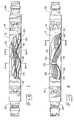
- an illustrative section of flexible steel conduit 42contains insulated conductors such as 46 , 48 , and 50 along with a stranded insulation-free copper conductor 44 which is connected to an electrical ground at the left end thereof.
- the groundingis similar to that shown in FIGS. 1 — 3 .
- the stranded conductor 44touches and grounds several regions such as 60 and 62 of the conduit 42 interior surface.
- Numerous replications of an experimental insertion of a certain number of insulated conductors and a ground conductormay be performed and the number of annuli in which grounding contact occurs, for each replication, counted.
- the histogramtends to become a smooth continuous frequency distribution. With the frequency distribution established by an adequate number of replications, the probability of achieving at least a certain number of grounded annular regions along the enclosure for the particular enclosure geometry, and the number and type of conductors, is simply the area under the distribution to the right of the particular number.
- the particular distributionis a function of the geometry of the enclosure, the number and rigidity of the conductors and numerous other factors. If it is desired to increase the probability of achieving adequate grounding, that is, to skew the distribution further toward the right, any of several techniques could be employed.
- the gathering or bundling together of some or all of the insulated conductors as shown in FIGS. 4 and 5enhances the likelihood of achieving at least some specified number of grounded annuli.
- making the ground conductor 20 or 44 of a greater number of strands, or of less tightly twisted strandsincreases the ground conductor flexibility and serves to skew the distribution further to the right.
- a reduction of the number of insulated conductors or increasing the number of ground conductorswould also achieve an increase in the likelihood of achieving adequate grounding.
- the probabilistic grounding of an elongated electrically conductive enclosureis achieved by introducing a flexible stranded insulation-free conductor into the enclosure along with a plurality of insulated conductors, bundling the insulated conductors together, terminating the insulation-free conductor near at least one end thereof to an electrical ground, and allowing the insulation-free conductor to contact the enclosure interior in a plurality of randomly distributed locations along the elongated extent thereof.
- the bundlingenhances the random grounding by preventing the insulated conductors from isolating the insulation free conductor from the enclosure.
- the conventional technique of providing grounding clamps at one or both conduit endsleaves a central conduit portion which is not effectively grounded.
- the grounding of numerous intermediate conduit regionsprovided by the present invention solves this problem.
Landscapes
- Engineering & Computer Science (AREA)
- Architecture (AREA)
- Civil Engineering (AREA)
- Structural Engineering (AREA)
- Details Of Indoor Wiring (AREA)
Abstract
Description
Claims (6)
Priority Applications (1)
| Application Number | Priority Date | Filing Date | Title |
|---|---|---|---|
| US09/527,880US6455777B1 (en) | 2000-03-20 | 2000-03-20 | Using bare stranded copper wire for grounding to conduit or steel channel |
Applications Claiming Priority (1)
| Application Number | Priority Date | Filing Date | Title |
|---|---|---|---|
| US09/527,880US6455777B1 (en) | 2000-03-20 | 2000-03-20 | Using bare stranded copper wire for grounding to conduit or steel channel |
Publications (1)
| Publication Number | Publication Date |
|---|---|
| US6455777B1true US6455777B1 (en) | 2002-09-24 |
Family
ID=24103324
Family Applications (1)
| Application Number | Title | Priority Date | Filing Date |
|---|---|---|---|
| US09/527,880Expired - LifetimeUS6455777B1 (en) | 2000-03-20 | 2000-03-20 | Using bare stranded copper wire for grounding to conduit or steel channel |
Country Status (1)
| Country | Link |
|---|---|
| US (1) | US6455777B1 (en) |
Cited By (7)
| Publication number | Priority date | Publication date | Assignee | Title |
|---|---|---|---|---|
| US20040149868A1 (en)* | 2003-01-31 | 2004-08-05 | Schultz David J. | Support for network interface devices |
| FR2868888A1 (en)* | 2004-04-07 | 2005-10-14 | Sofanou Sa | Sheath for protecting electric cable bundle, has reinforcement connection traversing two openings to maintain two edges of slot in support one against another by emerging outside sheath`s body in adjustment position of curvilinear length |
| US20080032534A1 (en)* | 2005-02-17 | 2008-02-07 | Pent Technologies, Inc. | Method of branching power around an obstacle |
| US20080156529A1 (en)* | 2006-08-18 | 2008-07-03 | Airbus France | Attachment system for cables and support for cables used in aeronautic construction |
| US20090272557A1 (en)* | 2006-05-24 | 2009-11-05 | Vestas Wind Systems A/S | Earthing system for a wind turbine connected to a utility grid and for a wind turbine park |
| US20100263308A1 (en)* | 2009-04-20 | 2010-10-21 | Olvera Robert E | Systems and Methods for Modular Building Construction with Integrated Utility Service |
| US7993150B1 (en) | 2010-03-12 | 2011-08-09 | Haworth, Inc. | Power distribution assembly with grounding feature |
Citations (20)
| Publication number | Priority date | Publication date | Assignee | Title |
|---|---|---|---|---|
| GB105411A (en) | ||||
| US2739998A (en) | 1951-03-05 | 1956-03-27 | Sidney D Kretzer | Supplemental grounding device for electrical conducting cables |
| GB853615A (en) | 1957-03-11 | 1960-11-09 | Sidney Alfred Lewis Weeden | Improvements in or relating to earthing clamps |
| US3135469A (en)* | 1962-04-02 | 1964-06-02 | Neil H Hanson | Portable electrical outlet and lighting assembly |
| US3655905A (en) | 1971-01-04 | 1972-04-11 | Jimmy C Ray | Method and means for keeping cables dry |
| US3909502A (en)* | 1973-07-19 | 1975-09-30 | Technilec Sarl | Column for electrical supply cables |
| US4166195A (en)* | 1977-07-22 | 1979-08-28 | Isotrol Systems | Duct apparatus for distribution of isolated power and equipotential ground |
| US4791237A (en) | 1987-11-18 | 1988-12-13 | Preformed Line Products Company | Cable suspension assembly with grounding mechanism |
| US4808072A (en) | 1987-09-17 | 1989-02-28 | United Technologies Corporation | Electrical grounding connector for a helicoptor rotor |
| US4861940A (en) | 1988-09-07 | 1989-08-29 | Carpenter Jr Roy B | Automated moisturized grounding electrode system |
| US4885428A (en) | 1988-04-19 | 1989-12-05 | A-1 Construction Company | System for electrical grounding |
| US5062246A (en)* | 1988-11-16 | 1991-11-05 | Sykes Christopher C | Partition structures and frame elements therefor |
| US5218167A (en)* | 1986-11-28 | 1993-06-08 | Gasque Jr Samuel N | Cable assembly with lightning protection |
| US5383318A (en)* | 1992-11-04 | 1995-01-24 | Herman Miller, Inc. | Raceway cable retention and accommodation apparatus |
| US5784841A (en)* | 1996-01-11 | 1998-07-28 | Patio Enclosures, Inc. | Electrical raceway housed in a structural member |
| US5901756A (en)* | 1997-09-03 | 1999-05-11 | Goodrich; John J. | Flexible wear sleeve |
| US5930100A (en)* | 1996-10-31 | 1999-07-27 | Marilyn A. Gasque | Lightning retardant cable |
| US5956445A (en)* | 1994-05-20 | 1999-09-21 | Belden Wire & Cable Company | Plenum rated cables and shielding tape |
| US6201687B1 (en)* | 1998-10-09 | 2001-03-13 | American Access Technologies, Inc. | Modular furniture wall system and method for telecommunications equipment and wire management in an open office architecture |
| US6218612B1 (en)* | 1996-03-14 | 2001-04-17 | Mckitrick Mark A. | Modular panel partition system |
- 2000
- 2000-03-20USUS09/527,880patent/US6455777B1/ennot_activeExpired - Lifetime
Patent Citations (20)
| Publication number | Priority date | Publication date | Assignee | Title |
|---|---|---|---|---|
| GB105411A (en) | ||||
| US2739998A (en) | 1951-03-05 | 1956-03-27 | Sidney D Kretzer | Supplemental grounding device for electrical conducting cables |
| GB853615A (en) | 1957-03-11 | 1960-11-09 | Sidney Alfred Lewis Weeden | Improvements in or relating to earthing clamps |
| US3135469A (en)* | 1962-04-02 | 1964-06-02 | Neil H Hanson | Portable electrical outlet and lighting assembly |
| US3655905A (en) | 1971-01-04 | 1972-04-11 | Jimmy C Ray | Method and means for keeping cables dry |
| US3909502A (en)* | 1973-07-19 | 1975-09-30 | Technilec Sarl | Column for electrical supply cables |
| US4166195A (en)* | 1977-07-22 | 1979-08-28 | Isotrol Systems | Duct apparatus for distribution of isolated power and equipotential ground |
| US5218167A (en)* | 1986-11-28 | 1993-06-08 | Gasque Jr Samuel N | Cable assembly with lightning protection |
| US4808072A (en) | 1987-09-17 | 1989-02-28 | United Technologies Corporation | Electrical grounding connector for a helicoptor rotor |
| US4791237A (en) | 1987-11-18 | 1988-12-13 | Preformed Line Products Company | Cable suspension assembly with grounding mechanism |
| US4885428A (en) | 1988-04-19 | 1989-12-05 | A-1 Construction Company | System for electrical grounding |
| US4861940A (en) | 1988-09-07 | 1989-08-29 | Carpenter Jr Roy B | Automated moisturized grounding electrode system |
| US5062246A (en)* | 1988-11-16 | 1991-11-05 | Sykes Christopher C | Partition structures and frame elements therefor |
| US5383318A (en)* | 1992-11-04 | 1995-01-24 | Herman Miller, Inc. | Raceway cable retention and accommodation apparatus |
| US5956445A (en)* | 1994-05-20 | 1999-09-21 | Belden Wire & Cable Company | Plenum rated cables and shielding tape |
| US5784841A (en)* | 1996-01-11 | 1998-07-28 | Patio Enclosures, Inc. | Electrical raceway housed in a structural member |
| US6218612B1 (en)* | 1996-03-14 | 2001-04-17 | Mckitrick Mark A. | Modular panel partition system |
| US5930100A (en)* | 1996-10-31 | 1999-07-27 | Marilyn A. Gasque | Lightning retardant cable |
| US5901756A (en)* | 1997-09-03 | 1999-05-11 | Goodrich; John J. | Flexible wear sleeve |
| US6201687B1 (en)* | 1998-10-09 | 2001-03-13 | American Access Technologies, Inc. | Modular furniture wall system and method for telecommunications equipment and wire management in an open office architecture |
Cited By (10)
| Publication number | Priority date | Publication date | Assignee | Title |
|---|---|---|---|---|
| US20040149868A1 (en)* | 2003-01-31 | 2004-08-05 | Schultz David J. | Support for network interface devices |
| FR2868888A1 (en)* | 2004-04-07 | 2005-10-14 | Sofanou Sa | Sheath for protecting electric cable bundle, has reinforcement connection traversing two openings to maintain two edges of slot in support one against another by emerging outside sheath`s body in adjustment position of curvilinear length |
| US20080032534A1 (en)* | 2005-02-17 | 2008-02-07 | Pent Technologies, Inc. | Method of branching power around an obstacle |
| US7524203B2 (en)* | 2005-02-17 | 2009-04-28 | Group Dekko, Inc. | Method of branching power around an obstacle |
| US20090272557A1 (en)* | 2006-05-24 | 2009-11-05 | Vestas Wind Systems A/S | Earthing system for a wind turbine connected to a utility grid and for a wind turbine park |
| US8383933B2 (en)* | 2006-05-24 | 2013-02-26 | Vestas Wind Systems A/S | Earthing system for a wind turbine connected to a utility grid and for a wind turbine park |
| US20080156529A1 (en)* | 2006-08-18 | 2008-07-03 | Airbus France | Attachment system for cables and support for cables used in aeronautic construction |
| US7692104B2 (en)* | 2006-08-18 | 2010-04-06 | Airbus France | Attachment system for cables and support for cables used in aeronautic construction |
| US20100263308A1 (en)* | 2009-04-20 | 2010-10-21 | Olvera Robert E | Systems and Methods for Modular Building Construction with Integrated Utility Service |
| US7993150B1 (en) | 2010-03-12 | 2011-08-09 | Haworth, Inc. | Power distribution assembly with grounding feature |
Similar Documents
| Publication | Publication Date | Title |
|---|---|---|
| US6566605B1 (en) | Multiple pair cable with individually shielded pairs that is easy to connect | |
| US5391836A (en) | Electric cable | |
| US4533790A (en) | Electrical conductor assembly | |
| US5696352A (en) | Stranded electrical wire for use with IDC | |
| EP3061161A1 (en) | Electrical cable connector | |
| US4933513A (en) | Electrical signal conductor assembly | |
| MX9801489A (en) | Local area network cabling arrangement. | |
| US4642480A (en) | Low profile cable with high performance characteristics | |
| US4976627A (en) | Grid/ground connector | |
| US6455777B1 (en) | Using bare stranded copper wire for grounding to conduit or steel channel | |
| US5516302A (en) | End feed connector for pre-bussed rigid conduit | |
| AU662951B2 (en) | Cutting and clamping terminal element | |
| US4808773A (en) | Low impedance cable | |
| US6173942B1 (en) | Electric fence network | |
| US5032086A (en) | Wiring harness for wall structures | |
| AU1987192A (en) | Pre-bussed rigid conduit | |
| EP4170825A1 (en) | Linearized magnet wire connector | |
| US20210375505A1 (en) | A twisted pair cable with a floating shield | |
| US11145434B2 (en) | Low voltage power conductor and system | |
| EP0744092B1 (en) | Electrical distribution system | |
| JP2505918Y2 (en) | Pressure contact type shield flat cable | |
| US20220375651A1 (en) | Electric Cable | |
| US20010023146A1 (en) | Cable connector | |
| AU719730B2 (en) | Electrical distribution system | |
| KR940009368B1 (en) | Bearing providing device and method of coaxial cable with ground termination bar |
Legal Events
| Date | Code | Title | Description |
|---|---|---|---|
| AS | Assignment | Owner name:DEKKO ENGINEERING, INC., INDIANA Free format text:ASSIGNMENT OF ASSIGNORS INTEREST;ASSIGNOR:LAUKHUF, GREGG EDWARD;REEL/FRAME:010641/0741 Effective date:20000313 | |
| STCF | Information on status: patent grant | Free format text:PATENTED CASE | |
| AS | Assignment | Owner name:PENT TECHNOLOGIES, INC., INDIANA Free format text:MERGER;ASSIGNORS:CUSTOM LIGHTS, INC.;DEKKO ENGINEERING, INC.;PENT PRODUCTS, INC.;AND OTHERS;REEL/FRAME:015139/0075 Effective date:20031226 | |
| FPAY | Fee payment | Year of fee payment:4 | |
| AS | Assignment | Owner name:DYMAS FUNDING COMPANY, LLC, AS AGENT,ILLINOIS Free format text:SECURITY AGREEMENT;ASSIGNORS:PENT TECHNOLOGIES, INC.;DEKKO TECHNOLOGIES, LLC;REEL/FRAME:017971/0469 Effective date:20060720 Owner name:DYMAS FUNDING COMPANY, LLC, AS AGENT, ILLINOIS Free format text:SECURITY AGREEMENT;ASSIGNORS:PENT TECHNOLOGIES, INC.;DEKKO TECHNOLOGIES, LLC;REEL/FRAME:017971/0469 Effective date:20060720 | |
| AS | Assignment | Owner name:GROUP DEKKO, INC., INDIANA Free format text:MERGER;ASSIGNOR:PENT TECHNOLOGIES, INC.;REEL/FRAME:021936/0719 Effective date:20071227 Owner name:GROUP DEKKO, INC.,INDIANA Free format text:MERGER;ASSIGNOR:PENT TECHNOLOGIES, INC.;REEL/FRAME:021936/0719 Effective date:20071227 | |
| FEPP | Fee payment procedure | Free format text:PAT HOLDER NO LONGER CLAIMS SMALL ENTITY STATUS, ENTITY STATUS SET TO UNDISCOUNTED (ORIGINAL EVENT CODE: STOL); ENTITY STATUS OF PATENT OWNER: LARGE ENTITY | |
| FPAY | Fee payment | Year of fee payment:8 | |
| AS | Assignment | Owner name:WELLS FARGO CAPITAL FINANCE, LLC, AS AGENT, ILLINO Free format text:SECURITY AGREEMENT;ASSIGNOR:GROUP DEKKO, INC.;REEL/FRAME:026503/0966 Effective date:20110624 | |
| FPAY | Fee payment | Year of fee payment:12 |