US6454773B1 - Multi-angle bone screw assembly using shape-memory technology - Google Patents
Multi-angle bone screw assembly using shape-memory technologyDownload PDFInfo
- Publication number
- US6454773B1 US6454773B1US09/944,662US94466201AUS6454773B1US 6454773 B1US6454773 B1US 6454773B1US 94466201 AUS94466201 AUS 94466201AUS 6454773 B1US6454773 B1US 6454773B1
- Authority
- US
- United States
- Prior art keywords
- members
- shape
- receiver member
- bone screw
- receiver element
- Prior art date
- Legal status (The legal status is an assumption and is not a legal conclusion. Google has not performed a legal analysis and makes no representation as to the accuracy of the status listed.)
- Expired - Lifetime
Links
- 210000000988bone and boneAnatomy0.000titleclaimsabstractdescription127
- 238000005516engineering processMethods0.000titledescription6
- 230000008859changeEffects0.000claimsdescription5
- 239000012781shape memory materialSubstances0.000claims4
- 238000003780insertionMethods0.000abstractdescription8
- 230000037431insertionEffects0.000abstractdescription8
- 230000006835compressionEffects0.000abstractdescription6
- 238000007906compressionMethods0.000abstractdescription6
- 239000000463materialSubstances0.000abstractdescription4
- 229910001285shape-memory alloyInorganic materials0.000description33
- 230000009466transformationEffects0.000description12
- 238000013459approachMethods0.000description8
- 230000008602contractionEffects0.000description6
- 210000004705lumbosacral regionAnatomy0.000description6
- 230000008901benefitEffects0.000description5
- 229920000147Styrene maleic anhydridePolymers0.000description4
- 229910045601alloyInorganic materials0.000description4
- 239000000956alloySubstances0.000description4
- 230000036760body temperatureEffects0.000description4
- 229910000734martensiteInorganic materials0.000description4
- 238000000034methodMethods0.000description4
- 230000008878couplingEffects0.000description3
- 238000010168coupling processMethods0.000description3
- 238000005859coupling reactionMethods0.000description3
- 238000013461designMethods0.000description3
- 230000004048modificationEffects0.000description3
- 238000012986modificationMethods0.000description3
- 239000007787solidSubstances0.000description3
- 238000001356surgical procedureMethods0.000description3
- 210000000115thoracic cavityAnatomy0.000description3
- PXHVJJICTQNCMI-UHFFFAOYSA-NNickelChemical compound[Ni]PXHVJJICTQNCMI-UHFFFAOYSA-N0.000description2
- RTAQQCXQSZGOHL-UHFFFAOYSA-NTitaniumChemical compound[Ti]RTAQQCXQSZGOHL-UHFFFAOYSA-N0.000description2
- 239000013078crystalSubstances0.000description2
- 230000007423decreaseEffects0.000description2
- 229910001000nickel titaniumInorganic materials0.000description2
- HLXZNVUGXRDIFK-UHFFFAOYSA-Nnickel titaniumChemical group[Ti].[Ti].[Ti].[Ti].[Ti].[Ti].[Ti].[Ti].[Ti].[Ti].[Ti].[Ni].[Ni].[Ni].[Ni].[Ni].[Ni].[Ni].[Ni].[Ni].[Ni].[Ni].[Ni].[Ni].[Ni]HLXZNVUGXRDIFK-UHFFFAOYSA-N0.000description2
- 230000007170pathologyEffects0.000description2
- 230000009467reductionEffects0.000description2
- 206010039722scoliosisDiseases0.000description2
- 230000000087stabilizing effectEffects0.000description2
- 239000010936titaniumSubstances0.000description2
- 241001125292Balaena mysticetusSpecies0.000description1
- RYGMFSIKBFXOCR-UHFFFAOYSA-NCopperChemical compound[Cu]RYGMFSIKBFXOCR-UHFFFAOYSA-N0.000description1
- 229910000990Ni alloyInorganic materials0.000description1
- BQCADISMDOOEFD-UHFFFAOYSA-NSilverChemical compound[Ag]BQCADISMDOOEFD-UHFFFAOYSA-N0.000description1
- 229910001069Ti alloyInorganic materials0.000description1
- HCHKCACWOHOZIP-UHFFFAOYSA-NZincChemical compound[Zn]HCHKCACWOHOZIP-UHFFFAOYSA-N0.000description1
- 230000004075alterationEffects0.000description1
- 210000004204blood vesselAnatomy0.000description1
- 229910052793cadmiumInorganic materials0.000description1
- BDOSMKKIYDKNTQ-UHFFFAOYSA-Ncadmium atomChemical compound[Cd]BDOSMKKIYDKNTQ-UHFFFAOYSA-N0.000description1
- 229910052802copperInorganic materials0.000description1
- 239000010949copperSubstances0.000description1
- 230000007812deficiencyEffects0.000description1
- 230000000694effectsEffects0.000description1
- 230000004927fusionEffects0.000description1
- 239000007943implantSubstances0.000description1
- 238000002513implantationMethods0.000description1
- 208000014674injuryDiseases0.000description1
- 230000001045lordotic effectEffects0.000description1
- 230000007246mechanismEffects0.000description1
- 229910052751metalInorganic materials0.000description1
- 239000002184metalSubstances0.000description1
- 150000002739metalsChemical class0.000description1
- 229910052759nickelInorganic materials0.000description1
- 230000008569processEffects0.000description1
- 230000001737promoting effectEffects0.000description1
- 230000000717retained effectEffects0.000description1
- 238000004904shorteningMethods0.000description1
- 229910052709silverInorganic materials0.000description1
- 239000004332silverSubstances0.000description1
- 238000005549size reductionMethods0.000description1
- 230000006641stabilisationEffects0.000description1
- 238000011105stabilizationMethods0.000description1
- 210000001519tissueAnatomy0.000description1
- 229910052719titaniumInorganic materials0.000description1
- 230000008733traumaEffects0.000description1
- 229910052725zincInorganic materials0.000description1
- 239000011701zincSubstances0.000description1
Images


Classifications
- A—HUMAN NECESSITIES
- A61—MEDICAL OR VETERINARY SCIENCE; HYGIENE
- A61B—DIAGNOSIS; SURGERY; IDENTIFICATION
- A61B17/00—Surgical instruments, devices or methods
- A61B17/56—Surgical instruments or methods for treatment of bones or joints; Devices specially adapted therefor
- A61B17/58—Surgical instruments or methods for treatment of bones or joints; Devices specially adapted therefor for osteosynthesis, e.g. bone plates, screws or setting implements
- A61B17/68—Internal fixation devices, including fasteners and spinal fixators, even if a part thereof projects from the skin
- A61B17/70—Spinal positioners or stabilisers, e.g. stabilisers comprising fluid filler in an implant
- A61B17/7001—Screws or hooks combined with longitudinal elements which do not contact vertebrae
- A61B17/7035—Screws or hooks, wherein a rod-clamping part and a bone-anchoring part can pivot relative to each other
- A61B17/7037—Screws or hooks, wherein a rod-clamping part and a bone-anchoring part can pivot relative to each other wherein pivoting is blocked when the rod is clamped
- A—HUMAN NECESSITIES
- A61—MEDICAL OR VETERINARY SCIENCE; HYGIENE
- A61B—DIAGNOSIS; SURGERY; IDENTIFICATION
- A61B17/00—Surgical instruments, devices or methods
- A61B17/56—Surgical instruments or methods for treatment of bones or joints; Devices specially adapted therefor
- A61B17/58—Surgical instruments or methods for treatment of bones or joints; Devices specially adapted therefor for osteosynthesis, e.g. bone plates, screws or setting implements
- A61B17/68—Internal fixation devices, including fasteners and spinal fixators, even if a part thereof projects from the skin
- A61B17/70—Spinal positioners or stabilisers, e.g. stabilisers comprising fluid filler in an implant
- A61B17/7001—Screws or hooks combined with longitudinal elements which do not contact vertebrae
- A61B17/7032—Screws or hooks with U-shaped head or back through which longitudinal rods pass
- A—HUMAN NECESSITIES
- A61—MEDICAL OR VETERINARY SCIENCE; HYGIENE
- A61B—DIAGNOSIS; SURGERY; IDENTIFICATION
- A61B17/00—Surgical instruments, devices or methods
- A61B17/56—Surgical instruments or methods for treatment of bones or joints; Devices specially adapted therefor
- A61B17/58—Surgical instruments or methods for treatment of bones or joints; Devices specially adapted therefor for osteosynthesis, e.g. bone plates, screws or setting implements
- A61B17/68—Internal fixation devices, including fasteners and spinal fixators, even if a part thereof projects from the skin
- A61B17/70—Spinal positioners or stabilisers, e.g. stabilisers comprising fluid filler in an implant
- A61B17/7001—Screws or hooks combined with longitudinal elements which do not contact vertebrae
- A61B17/7035—Screws or hooks, wherein a rod-clamping part and a bone-anchoring part can pivot relative to each other
- A61B17/7038—Screws or hooks, wherein a rod-clamping part and a bone-anchoring part can pivot relative to each other to a different extent in different directions, e.g. within one plane only
- A—HUMAN NECESSITIES
- A61—MEDICAL OR VETERINARY SCIENCE; HYGIENE
- A61B—DIAGNOSIS; SURGERY; IDENTIFICATION
- A61B17/00—Surgical instruments, devices or methods
- A61B2017/00831—Material properties
- A61B2017/00867—Material properties shape memory effect
- Y—GENERAL TAGGING OF NEW TECHNOLOGICAL DEVELOPMENTS; GENERAL TAGGING OF CROSS-SECTIONAL TECHNOLOGIES SPANNING OVER SEVERAL SECTIONS OF THE IPC; TECHNICAL SUBJECTS COVERED BY FORMER USPC CROSS-REFERENCE ART COLLECTIONS [XRACs] AND DIGESTS
- Y10—TECHNICAL SUBJECTS COVERED BY FORMER USPC
- Y10S—TECHNICAL SUBJECTS COVERED BY FORMER USPC CROSS-REFERENCE ART COLLECTIONS [XRACs] AND DIGESTS
- Y10S411/00—Expanded, threaded, driven, headed, tool-deformed, or locked-threaded fastener
- Y10S411/909—Fastener or fastener element composed of thermo-responsive memory material
- Y—GENERAL TAGGING OF NEW TECHNOLOGICAL DEVELOPMENTS; GENERAL TAGGING OF CROSS-SECTIONAL TECHNOLOGIES SPANNING OVER SEVERAL SECTIONS OF THE IPC; TECHNICAL SUBJECTS COVERED BY FORMER USPC CROSS-REFERENCE ART COLLECTIONS [XRACs] AND DIGESTS
- Y10—TECHNICAL SUBJECTS COVERED BY FORMER USPC
- Y10S—TECHNICAL SUBJECTS COVERED BY FORMER USPC CROSS-REFERENCE ART COLLECTIONS [XRACs] AND DIGESTS
- Y10S606/00—Surgery
- Y10S606/907—Composed of particular material or coated
- Y10S606/911—Memory material
Definitions
- the present inventionconcerns a bone screw assembly, and particularly an assembly useful for engagement in the vertebrae of the spine.
- the inventioncontemplates an assembly that is capable of supporting a bone engaging fastener at multiple angular orientations with respect to an elongated member extending along the spine.
- a bendable rodis disposed longitudinally along the length of the spine or vertebral column.
- the rodis preferably bent to correspond to the normal curvature of the spine in the particular region being instrumented.
- the rodcan be bent to form a normal kyphotic curvature for the thoracic region of the spine, or a lordotic curvature for the lumbar region.
- the rodis engaged to various vertebrae along the length of the spinal column by way of a number of fixation elements.
- fixation elementscan be provided which are configured to engage specific portions of the vertebra.
- one such fixation elementis a hook that is configured to engage the laminae of the vertebra.
- Another very prevalent fixation elementis a spinal screw which can be threaded into various aspects of the vertebral bone.
- the rodis situated on opposite sides of the spine or spinous processes.
- a plurality of bone screwsare threaded into a portion of several vertebral bodies, very frequently into the pedicles of these vertebrae.
- the rodsare affixed to these plurality of bone screws to apply corrective and stabilizing forces to the spine.
- the TSRH® Systemincludes elongated rods and a variety of hooks, screws and bolts all configured to create a segmental construct throughout the spine.
- the spinal rodis connected to the various vertebral fixation elements by way of an eyebolt.
- the fixation elementsare engaged to the spinal rod laterally adjacent to the rod.
- a variable angle screwis engaged to the spinal rod by way of an eyebolt. The variable angle screw allows pivoting of the bone screw in a single plane that is parallel to the plane of the spinal rod. Details of this variable angle screw can be found in U.S.
- Pat. No. 5,261,909 to Sutterlin et al.owned by the Assignee of the present invention.
- One goal achieved by the TSRH® Systemis that the surgeon can apply vertebral fixation elements, such as a spinal hook or a bone screw, to the spine in appropriate anatomic positions.
- the TSRH® Systemalso allows the surgeon to easily engage a bent spinal rod to each of the fixation elements for final tightening.
- the fixation elementsare the fixation elements for engagement between an -elongated rod and the spine.
- the fixation elementsthemselves include a body that defines a slot within which the spinal rod is received.
- the slotincludes a threaded bore into which a threaded plug is engaged to clamp the rod within the body of the fixation element.
- the CD® Systemincludes hooks and bone screws with this “open-back” configuration. Details of this technology can be found in U.S. Pat. No. 5,005,562 to Dr. Cotrel.
- One benefit of this feature of the CD® Systemis that the fixation element is positioned directly beneath the elongated rod. This helps reduce the overall bulkiness of the implant construct and minimizes the trauma to surrounding tissue.
- fixation elements of the CD® Systemare capable only of pivoting about the spinal rod to achieve variable angular positions relative to the rod. While this limited range of relative angular positioning is acceptable for many spinal pathologies, many other cases require more creative orientation of a bone screw, for instance, relative to a spinal rod. Certain aspects of this problem are addressed by the variable angle screw of the TSRHO System, as discussed in the '909 Patent.
- the bone screwis capable of various three-dimensional orientations with respect to the spinal rod. Screws of this type have been referred to as poly-axial or multi-axial bone screws.
- a bone screwwhich includes a spherical projection on the top of the bone screw.
- An externally threaded receiver membersupports the bone screw and a spinal rod on top of the spherical projection.
- An outer nutis tightened onto the receiver member to press the spinal rod against the spherical projection to accommodate various angular orientations of the bone screw relative to the rod. While this particular approach utilizes a minimum of components, the security of the fixation of the bone screw to the rod is lacking. In other words, the engagement or fixation between the small spherical projection on the bone screw and the spinal rod is readily disrupted when the instrumentation is subjected to the high loads of the spine, particularly in the lumbar region.
- an anchorreceives a semi-spherical head of a bone screw within a recess.
- the anchorincludes a rod channel transverse to the screw recess.
- the anchoris externally threaded to receive an internally threaded nut.
- the nutis threaded directly down onto the spinal rod to clamp the rod within the channel.
- a capis provided between the rod and nut. In both embodiments, neither the rod nor the external nut impart any clamping force onto the head of the bone screw.
- an anchorreceives a smei-spherical head of a bone screw within a recess.
- the anchorincludes a rod channel transverse to the screw recess.
- the anchoris externally threaded to receive an internally threaded nut.
- the nutis threaded directly down onto the spinal rod to clamp the rod within the channel.
- a capis provided between the rod and nut. In both embodiments, neither the rod nor the external not impart any clamping force onto the head of the bone screw.
- a spherical headed bone screwis supported within separate halves of a receiver member. The bottom of the halves are held together by a retaining ring. The top of the receiver halves are compressed about the bone screw by nuts threaded onto a threaded spinal rod.
- Harms et al.in U.S. Pat. No. 5,207,678, a receiver member is flexibly connected about a partially spherical head of a bone screw. Conical nuts on opposite sides of the receiver member are threaded onto a threaded rod passing through the receiver.
- the receiver memberflexibly compresses around the head of the bone screw to clamp the bone screw in its variable angular position.
- the spinal rodmust be threaded in order to accept the compression nuts. It is known that threaded rods can tend to weaken the rods in the face of severe spinal loads.
- the design of the bone screws in the '458 and '678 Patentsrequire a multiplicity of parts and are fairly complicated to achieve complete fixation of the bone screw.
- the '608 Patentdescribes a complicated array of components that includes a tapered lower portion defining a spherical recess to receive the head of a bone screw.
- the lower portionis slotted so that the lower portion can be compressed about the bone screw head by operation of a ring pushed down the tapered lower portion.
- a hollow cylindrical rod securing sleevefits over an upper portion of the coupling element that is operable to clamp the rod within the coupling element as the sleeve is pushed down onto the ring.
- the coupling elementincludes a threaded post onto which a nut is threaded that is operable to push the sleeve down onto the rod and onto the ring to compress the lower portion against the bone screw head.
- a threaded postonto which a nut is threaded that is operable to push the sleeve down onto the rod and onto the ring to compress the lower portion against the bone screw head.
- the second alternative in the Errico '157 Patentis similar to the approach taken in the Puno '555 Patent, except that the rod contacts the spherical head of the bone screw in the '157 Patent.
- An external nutis threaded directly down onto the spinal rod which then bears directly on the bone screw head to clamp the head within a spherical recess. While this design offers much greater simplicity than the Errico '608 Patent it suffers from the point contact between the rod and the spherical head of the bone screw. It is uncertain whether this clamping mechanism is sufficient to maintain the relative position between bone screw and spinal rod under severe spinal loads.
- shape-memory alloyIn recent years, a special material known as “shape-memory alloy” has found its way into the field of medical devices. These materials are alloys of known metals, such as copper and zinc, nickel and titanium, silver and cadmium, and others, that are known to exhibit a “shape-memory” in which a particular component formed of a shape-memory alloy (SMA) will change shape upon changes in temperature.
- SMAshape-memory alloy
- the shape-memory characteristics of SMAsoccur when the alloy changes from a martensitic crystal phase to an austenitic crystal phase. In the martensitic stage, the SMA is relatively weak and pliable. As the temperature of the SMA component is increased above a transformation temperature range, the SMA transforms to its austenitic phase in which the material is relatively strong with super-elastic properties. Generally, the strength and super-elastic characteristics of an SMA tend to increase toward the high temperature end of the transformation temperature range and decrease toward the low temperature end.
- an object made of an SMAis formed into a particular shape at a temperature that is either above or below the transformation temperature range. The object will then change shape as its temperature increases or decreases through that transformation temperature range.
- a deviceis formed into its in a shape at the high temperature, or the temperature above the transformation temperature range. The device is then cooled to be provided to the surgeon for implantation.
- One known application of SMA technology in the medical fieldis a vena cava filter that assumes a smaller shape at its low temperature, and then expands to its larger shape within a blood vessel when heated to body temperature.
- Nitinol®which has proven highly effective for devices placed within the human body because its transformation temperature range falls between room temperature and normal human body temperature.
- Shape-memory technologyhas also found its way into the field of orthodontics, as described in U.S. Pat. No. 5,551,871 to Besselink et al. This patent describes face bow head gear used for aligning teeth of a patient in which an SMA wire is used to align and hold the teeth of a patient.
- the '871 Patentalso discloses devices for use in treating scoliosis including a transverse connector and bone engaging fasteners that clamp to an elongated rod by way of shape-memory, characteristics. While the '871 Patent shows one use of SMA technology for spinal hooks and screws, the hooks and screws are only capable of pivoting about the axis of the rod. In this regard, the devices shown in the '871 Patent are similar to the components of the CD® System discussed above.
- the spinal rodcan be of any configuration—i.e., smooth, roughened, knurled or even threaded.
- This needalso encompasses the goal of minimizing the profile and bulk of any of the components used to engage the bone screw to the spinal rod in a variety of angular orientations. Moreover, it is desirable to reduce the number of components of the system that must be manipulated by the surgeon during a surgical procedure.
- FIG. 1is a side elevational view of a multi-axial screw assembly according to one embodiment of the present invention.
- FIG. 2is a side cross-sectional view of the screw assembly depicted in FIG. 1 .
- FIG. 3is a side elevational view of the screw assembly shown in FIG. 1, with a spinal rod engaged within the assembly.
- FIG. 4is a side elevational view of the assembly as shown in FIG. 3, with the assembly rotated 90° to show the rod extending through the multi-axial screw assembly.
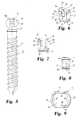
- FIG. 5is a side elevational view of a bone screw adapted for use with the multi-axial screw assembly shown in FIG. 1 .
- FIG. 6is a top perspective view of a receiver member used with the multi-axial screw assembly shown in FIG. 1 .
- FIG. 7is a side elevational view of the receiver member shown in FIG. 6 .
- FIG. 8is an end elevational view of the receiver member shown in FIG. 6 .
- FIG. 9is a top elevational view of a locking ring used with the multi-axial screw assembly shown in FIG. 1 .
- FIG. 10is a top perspective view of a receiver member according to an additional embodiment of the invention.
- FIG. 11is a cross-sectional view of the receiver member depicted in FIG. 10 .
- FIG. 12is a side elevational view of the receiver member shown in FIG. 10, with a spinal rod and SMA ring depicted in phantom lines engaged to the receiver member.
- FIG. 13is an end elevational view of the receiver member shown in FIG. 10 .
- a spinal fixation assemblywhich includes a bone engaging fastener, such as a bone screw, and an elongated member, such as a spinal rod.
- the fixation assemblyincludes a multi-axial screw assembly that permits fixation of the bone screw to the spinal rod at any of a plurality of angles in three-dimensional space relative to the rod.
- the bone screwcan pivot relative to the rod about a cone directly beneath the spinal rod.
- the bone screwincludes a head that is at least partially spherical. The head is preferably truncated to form a flat upper surface within which a tool engaging recess is defined.
- the multi-axial screw assemblyfurther includes a receiver member defining a bore therethrough from its top end to its bottom end.
- the borefurther includes a recess for receiving the head of the bone screw, with a lower opening at the bottom end of the receiver member through which a lower portion of the bone screw extends to engage the spine.
- the receiver memberalso includes a channel transverse to the bore and communicating with the bore to receive the spinal rod. Both the bone screw and the spinal rod can be inserted into the receiver member through an upper opening.
- a locking ringis provided at the bottom of the receiver member.
- the locking ringis configured to closely fit around the perimeter of the receiver member and particularly overlapping the recess within which the head of the bone screw resides.
- the locking ringis formed of a shape-memory alloy (SMA) configured so that the locking ring has a first diameter that is larger than a second diameter, and in which the locking ring transforms from the first diameter to the second diameter when heated to the body temperature of the patient.
- SMAshape-memory alloy
- the receiver memberincludes thin slots on opposite sides of the receiver to facilitate compression of the receiver member about the head of the bone screw.
- opposite slotsare provided in the receiver member that are offset by 90° from the other slots. These slots extend into the channel within which the spinal rod is received.
- a second SMA locking ringis disposed over the top of the receiver member to apply a clamping force from the top of the receiver member. In this manner, the spinal rod can be engaged by the receiver member as the upper SMA locking ring transforms to its austenitic shape.
- the receiver memberis modified to permit entry of the bone screw head from the bottom of the receiver member.
- the receiver memberis provided with a plurality of slots emanating from the bottom of the member. The recess within the member is enlarged adjacent the bottom of the receiver member to accept the bone screw head by expansion of the receiver member at the slots. The slots terminate adjacent the rod channel so that transformation of the lower SMA ring will provide some clamping force to the spinal rod.
- the upper portion of the receiver memberwill provide further clamping force upon temperature transformation of the upper SMA ring.
- the present inventionprovides an assembly that permits fixation of a bone engaging fastener to an elongated member at a plurality of three-dimensional angular orientations relative to the elongated member.
- the preferred embodiments of the inventive multi-axial screw assemblyprovides the advantage of a solid fixation between a spinal rod and a bone screw, regardless of the angle between the two components.
- a further benefit of the present inventionresides in the minimum number of components necessary to effect this solid fixation. Yet another benefit is achieved by the use of shape-memory technology to eliminate the need for extra mechanical fasteners and engagement instruments that are prevalent width prior devices.
- a spinal fixation assemblyincludes an elongated member, such as the spinal rod, and a multi-axial screw assembly, such as the assembly 10 shown in FIGS. 1 and 2.
- the spinal fixation assemblycan use a multi-axial screw assembly 10 at one or more locations along the length of the spine.
- the spinal fixation assemblycan be used in a variety of applications within the spine to address a wide range of spinal pathologies. For example, a fixation assembly can be limited to the lumbar region for fixation following a diskectomy. Alternatively, a spinal fixation assembly can extend substantially along the entire length of the spine, such as along the thoracic and lumbar regions, to correct a deformity, such as scoliosis.
- a spinal fixation assembly implementing the present inventioncan provide for fixation and stabilization of the cervical spine, such as might occur following a fracture or dislocation. It is of course understood by a person of skill in this art that the components of the spinal fixation system will vary depending upon the region of the spine, and the treatment to be administered. In certain applications, a number of hooks will engage aspects of several vertebrae. In another fixation assembly, bone screws can be threaded into portions of the vertebrae, as all operating as an anchor for an elongated member, such as a spinal rod.
- engagement between the elongated member and one or more vertebraemay require orientation of a fixation member at a wide range of three dimensional angles relative to the elongated member.
- a fixation membersuch as a spinal rod
- engagement of a fixation member to the spinemay require that the fixation member assume various angles relative to the spinal rod, and certainly angles that may not be achieved by prior devices and systems.
- the assembly 10includes a bone screw 11 that is mounted within a receiver member 12 .
- a pair of shape-memory alloy (SMA) locking rings 13are provided to clamp the receiver member 12 about at least the bone screw 11 .
- SMAshape-memory alloy
- FIGS. 3 and 4A use of the screw assembly 10 as part of a spinal fixation system is depicted in FIGS. 3 and 4.
- the elongated memberis a spinal rod R that extends through the receiver member 12 .
- the bone screw 11is capable of assuming a range of angles up to an angle A relative to the spinal rod. It is understood that the bone screw can sweep through a cone defined at the angle A, although the angle is only depicted in the plane of the paper in the figure.
- the bone screw 11includes a threaded shank 15 that carries threads configured to engage the bone of a vertebra.
- the threadscan be cancellous threads that are configured to engage the vertebral body.
- the bone screw 11also includes a head 16 that is preferably at least partially spherically shaped.
- the head 16includes a flat surface 16 a within which is defined a tool receiving recess 17 .
- the tool receiving recess 17can be configured to accept any type of known driving tool.
- the tool receiving recess 17is a hex recess to receive the hex end of a driving tool.
- the tool receiving recess 17allows for insertion of the bone screw 11 into the vertebra.
- the head 16 of bone screw 11is preferably substantially spherically shaped to include a spherical surface 18 .
- the spherical surface 18provides for bearing contact with the receiver member 12 so that the bone screw can be arranged at a variety of angular orientations relative to the receiver member, with and without the spinal rod R extending therethrough.
- an annular relief 19is provided between the spherical head 16 and the threaded shank 15 . Referring back to FIGS. 1 and 2, it can be seen that that annular relief 19 allows the bone screw 11 to have a wider range of movement within the receiver member 12 and helps avoid contact between the shank of the bone screw and the bottom of the receiver member.
- the receiver member 12defines a spherical recess 26 adjacent the bottom end of the member.
- the recessis preferably at least partially spherical, as shown more clearly in FIG. 2 .
- the spherical recess 26has a diameter that is substantially equal to the diameter of the spherical surface 18 of the head of the bone screw 11 .
- the spherical recess 26contacts only a portion of the spherical surface 18 of the bone screw 11 . In the illustrated embodiment, this contact amounts to about one-third of the spherical surface 18 .
- the receiver member 12includes a flared opening 27 at the bottom of the member. Again looking back to FIG. 2, this flared opening 27 can be seen as providing for an enhanced range of movement of the bone screw 11 as the spherical head 16 pivots within the spherical recess 26 .
- the flared opening 27communicates with the spherical recess 26 at a diameter that is less than the largest diameter of the spherical head 16 of the bone screw 11 . In this manner, the bone screw 11 will not pass through the bottom of receiver member 12 .
- the receiver memberfurther defines a central bore 25 extending from the top of the member to the recess 26 .
- the central bore 25has a diameter that is approximately equal to the diameter of the spherical recess 26 , or more particularly the diameter of the head 16 of the bone screw 11 .
- the bone screwcan be inserted into the receiver member 12 through an upper opening 28 .
- the screw 11passes through the bore 25 so that the head 16 of the bone screw can be pressed into the spherical recess 26 at the base of bore 25 .
- the bore 25can also allow access for a driving tool to engage the tool receiving recess 17 of the bone screw 11 . In this manner, the bone screw can be threaded into a vertebra with the screw provisionally retained within the receiver member 12 .
- the receiver member 12has the general configuration of a cylinder having truncated side walls.
- the receiver member 12includes opposite curved side walls 30 separated by opposing flat side walls 32 .
- the flat side walls 32define a rod channel 33 that extends transversely across bore 25 in the receiver member 12 .
- An angled guide wall 34can be formed on top of each of the curved side walls 30 to guide a spinal rod R (FIG. 3) through the upper opening 28 and into the rod channel 33 .
- the rod channel 33is substantially circular and has a diameter that is substantially equal to the outer diameter of the spinal rod R to be disposed within the channel.
- the flat side walls 32also define a linear channel 35 communicating between the rod channel 33 and the upper opening 28 .
- the linear channel 35defines a width that is slightly smaller than the diameter of the rod channel 33 and than the largest diameter of the spinal rod R to be disposed within the rod channel 33 .
- the spinal rodcan be at least provisionally held within the rod channel 33 prior to tightening of the locking rings 13 about the receiver member 12 .
- the width of the linear channel 35is less than the diameter of the bore 25 .
- the preferred embodimentcontemplates a receiver member 12 that is split at a pair of opposite upper slots 36 and a pair of opposite lower slots 37 .
- the upper slots 36are defined from the base of the rod channel 33 .
- the upper slots 36permit slight contraction of the upper portion of the receiver member 12 about a spinal rod R disposed within the rod channel 33 .
- the upper slots 36also permit slight expansion of the receiver member and particular the bore 25 during insertion of the bone screw 11 and linear channel 35 during insertion of the rod R from the upper opening 28 .
- the lower slots 37are disposed at the bottom of the receiver member 12 and intersect the flared opening 27 and the spherical recess 26 , in accordance with the preferred embodiment.
- the lower slots 37allow contraction of the lower portion of the-receiver member 12 about the head 16 of the bone screw 11 .
- the upper slots 36are offset by 90° relative to the lower slots 37 . More particularly, the upper slots 36 are defined in the flat side walls 32 , while the lower slots 37 are defined in the curved side walls 30 .
- the receiver member 12defines features for supporting the pair of SMA locking rings 13 .
- an upper engagement groove 39is defined within the curved side walls 30 at the top of the receiver member 12 .
- a lower engagement groove 40is also defined in the curved side walls 30 at the bottom of the receiver member 12 .
- the upper and lower grooves 39 , 40are configured to closely receive a corresponding locking ring 13 thereabout.
- An upper lip 41is provided at the upper end of the engagement groove 39 to retain a locking ring 13 at the top of receiver member 12 .
- a lower lip 42helps retain a locking ring 13 at the bottom of the receiver member 12 .
- the lower engagement groove 40is situated within the same plane as the spherical recess 26 . In this manner, when the locking ring 13 at the bottom of the receiver member 12 contracts, the greatest amount of force will be applied directly from the receiver member 12 through the recess 26 to the spherical head 16 of the bone screw 11 .
- the upper engagement groove 39is situated as close to the top of the receiver member 12 as possible so that upon contraction of the upper locking ring 13 , the receiver member 12 wraps slightly around the spinal rod R to clamp the rod within the rod channel 33 .
- each of the locking rings 13has a substantially similar configuration. As shown in FIG. 9, the locking rings 13 are substantially rectangular with cured end walls to substantially conform to the truncated cylindrical configuration of the receiver member 12 . In other words, each of the locking rings 13 includes opposite curved walls 45 separated by opposite flat walls 46 . Preferably, the locking rings 13 define an opening 47 between the walls 45 , 46 that conforms to the upper engagement groove 39 and lower engagement groove 40 . Also preferably, the ring 13 has an effective diameter between the curved walls 45 that is substantially equal to the diameter of the engagement grooves 39 , 40 when the SMA locking ring 13 is in its martensitic or room temperature state.
- the body temperature of the patientwill increase the temperature of the locidng rings 13 .
- the locking rings 13move from their martensitic to their austenitic phases. In the austenitic phase at the higher temperature, the locking rings 13 deform to a smaller size, as reflected by the curved walls 45 ′ and flat walls 46 ′.
- the locking ring 13 in the upper groove 39can be formed so that only the flat walls 46 shorten, while locking ring for the lower groove 40 can be formed so that only the curved walls 45 shorten.
- the curved walls 45 of the upper locking ringcan press the curved side walls 30 of the receiver member 12 toward each other and about the spinal rod R as the flat walls shorten.
- the shortening of the curved walls 46 of the lower locking ringcan cause the side walls 46 of the ring to press the side walls 32 of the receiver member 12 together about the screw head.
- the multi-axial screw assembly 10is initially provided with the spherical head 16 of the bone screw 11 disposed within the spherical recess 26 of the receiver member 12 .
- a locking ring 13is situated within the lower engagement groove 40 to loosely retain the bone screw within the receiver member.
- This initially assembled arrangementcan be introduced to the surgical site and the bone screw 11 threaded into the vertebra according to the protocol for the particular spinal procedure.
- a driving toolcan pass through the bore 25 of the receiver member 12 , with the bore being substantially aligned with the tool receiving recess 17 in the head of the bone screw.
- the bone screw 11is driven into the vertebra to a recommended depth for adequate fixation, but preferably not so deep that the bottom of the receiver member 12 will contact or press against the vertebral bone.
- the receiver member 12In order for the multi-axial capability of the assembly 10 to be realized, the receiver member 12 must be free to pivot in three dimensions about the head 16 of the bone screw 11 .
- the spinal rod Rcan be introduced into the rod channel 33 , as shown in FIG. 3 .
- the receiver member 12is configured so that the spinal rod R does not contact the bone screw 11 , regardless of the relative angle between the rod, receiver member 12 and bone screw head 16 . Instead, the rod R is supported in the rod channel 33 by the flat side walls 32 . With the rod properly positioned, the second locking ring 13 can be disposed on the receiver member 12 , and particularly in the upper engagement groove 39 .
- the locking rings 13are at least initially at or below room temperature. Once the first locking ring 13 is situated within the patient upon insertion of the bone screw 11 , the temperature of the locking ring 13 and the lower engagement groove 40 will increase. Once that temperature increases beyond the transformation temperature range of the SMA, the locking ring 13 will contract to the shape shown in FIG. 9 as indicated by curved walls 45 ′ and flat walls 46 ′. At this point, the spherical head 16 of the bone screw 11 will be firmly clamped within the spherical recess 26 of the receiver member 12 .
- the locking ring 13 in the upper engagement groove 39will also contract as its temperature increases above the transformation temperature range. At that point, then, the receiver member 12 will be contracted about the spinal rod R to firmly clanp the spinal rod within the rod channel 33 .
- both SMA locking rings 13have moved to their austenitic phase, the multi-axial screw assembly 10 is firmly clamped and the bone screw 11 is solidly fixed to the spinal rod R.
- the present inventionprovides a screw assembly 10 that offers a low profile and minimum prominence.
- the bone screwis attached to the spinal rod directly beneath the rod, or in line between the rod and the vertebra.
- the overall bulk or prominence of the present inventionis minimized by the use of the SMA locking rings 13 , which is in contrast to the prior devices which require some form of external cap or nut threaded onto the top of a receiver member.
- the present inventionprovides a screw assembly that can be tightened from the top, meaning that the bone screw 11 can be threaded onto the vertebra from the top.
- the spinal rodis loaded from the top, which can greatly simplify a spinal surgical procedure.
- the roddoes not need to be preloaded into the receiver member 12 .
- the multi-axial capabilityallows a bone screw to be connected with a spinal rod with minimal contouring of the rod being necessary.
- the bone screw 11is configured for engagement in the lumbar spine and has an overall length of about 2.126 inches.
- the spherical head 16 and particularly the spherical surface 18 of the bone screwhas an outer diameter of about 0.315 inches, while the annular relief 19 has a diameter of about 0.236 inches.
- the receiver member 12has an overall height of about 0.609 inches.
- the receiver memberdefines a bore 25 having a diameter of about 0.295 inches, which is slightly smaller than the outer diameter of the spherical head 16 of the bone screw 11 .
- the spherical recess 26has a diameter of approximately 0.315 inches to correspond to the outer diameter of the head of the bone screw 11 .
- the flared opening 27 of the receiver member 12increases to an opening diameter of 0.400 inches, in the specific embodiment.
- the receiver member 12has a width between the flat side wails 32 of 0.354 inches. This corresponds to the room temperature distance between the flat walls 46 of the locking rings 13 .
- the receiver member 12has a maximum dimension between the curved side walls 30 of 0.462 inches at the upper and lower engagement grooves 39 , 40 . This dimension is substantially the same as the maximum distance between the curved walls 45 of the locking rings 13 in their room temperature configuration.
- the upper slots 36 and lower slots 37have a width of about 0.020 inches, which means that the receiver member 12 can contract over that distance at the respective slots.
- the flat walls 46 of the locking rings 13must shrink by about 0.020 inches. This change in length amounts to about a 4% reduction in the overall length of each of the flat walls 46 . This percentage reduction is typical for many medical grade SMAs; however, other SMAs could be used having different transformation capabilities,
- the locking rings 13are formed of Nitinol®.
- a modified receiver member 52is provided as shown in FIGS. 10-13.
- the receiver member 52includes a bore 55 extending through a small portion of the center of the receiver member.
- the boreopens into a spherical recess 56 that is configured so that the recess has a maximum diameter that is larger than the maximum diameter of the bore 55 .
- the recesshas a diameter of about 0.320 in. to accomodate a similarly sized bone screw head, while the bore 55 has a diameter of about 0.250 in.
- the recess 56is only partially spherical, meaning that it does not extend entirely around the spherical head of a bone screw disposed within the recess.
- the recess 58opens to the bottom of the receiver member at a flared opening 57 .
- the recesscontacts about half of the surface area of the bone screw, with the greater amount of contact at the upper hemisphere of the recess.
- the recess 56intersects the bore 55 at the bore's diameter of 0.250 in.
- the recess 56intersects the flared opening 57 at a diameter that is greater than the diameter of the bore, namely about 0.305 in.
- An upper opening 58is provided at the top end of the receiver member, in one specific embodiment, preferably to permit insertion of the spinal rod.
- the bone screwwhich can be the bone screw 11 described above, is loaded into the receiver member 52 from the bottom of the member.
- the upper opening 58need not be provided for insertion of the bone screw, as in the embodiment of FIGS. 1-9.
- the bore 55may be eliminated unless it is needed for access by a screw insertion tool.
- the receiver member 52includes curved side walls 60 and flat side walls 62 similar to the receiver member 12 .
- the member 52includes a rod channel 63 defined in the side walls that intersects a portion of the bore 55 .
- the rod channel 63opens to a linear channel 65 that incorporates angled guide walls 64 at the top end of the receiver member.
- the linear channel 65has a width that is substantially equal to the diameter of the bore 55 and rod channel 63 .
- the receiver member 52is adapted to receive SMA locking rings at the top and bottom of the member.
- the receiver member 52includes upper and lower engagement grooves 69 , 70 defined by upper and lower lips 71 , 72 .
- An SMA locking ring 13fits into each of the grooves 69 , 70 and operates in the thermally responsive manner described above to contract about the receiver member.
- the receiver member 52includes short slots 66 defined in the flat side walls 62 , and long slots extending from the bottom of the receiver in the curved side walls 60 .
- the one short slotis provided in each flat side wall 62 that emanates from the bottom of the receiver member and that terminates generally in the middle of the spherical recess 56 .
- the three long slotsare provided in the curved side walls 60 . The long slots extend from the bottom of the receiver member and terminate adjacent the level of the bottom of the rod channel 63 .
- the receiver member 52 of the embodiment in FIGS. 10-13permits bottom loading of the bone screw by brief expansion of the spherical recess 56 and flared opening 57 at the slots 66 and 67 .
- the lower SMA locking ring 13can be added once the bone screw head is situated within the recess 56 by slightly compressing the receiver member at the slots 66 , 67 . Contraction of the lower SMA locking ring 13 due to temperature change again operates to compress the receiver member at the lower engagement groove 70 by closing the slots.
- only the short slots 66 in the flat side walls 62will close to clamp the bone screw head within the spherical recess 56 .
- the long slots 67will also collapse upon a size reduction of the SMA locking ring.
- Fixation of a spinal rod within the receiver member of this embodimentcan be accomplished in many ways.
- the upper groove 69 and locking ring 13 ′is situated closer to the rod channel 63 , and consequently the spinal rod R′, than with the previous embodiment.
- Fixation of the rod R′ within the rod channel 63can also be effected by compression of the upper portion of the receiver member, and particularly the upper portion of the curved side walls 60 , by SMA contraction of the upper locking ring 13 ′.
- additional compression of the receiver member 52can be accomplished by contraction of the SMA locking ring in the lower engagement groove which contract the slots 66 and 67 .
- the preferred embodimentcontemplates a bone screw, such as screw 11
- other bone engaging fastenersare contemplated.
- the multi-axial capabilitiescan be equally applicable to a vertebral hook, for example.
- the components of the multi-axial screw assembly 10can be sized according to the portion of the spine within which the assembly is to be used. In the illustrated embodiment, the components are dimensioned for use in the lumbar spine. It is understood that smaller components would be required in the thoracic and cervical spine, while the multi-axial movement capabilities can be equally well suited throughout the entire length of the spine. Further, while the invention is described for engagement to an elongated cylindrical rod, other elongated members are contemplated.
Landscapes
- Health & Medical Sciences (AREA)
- Orthopedic Medicine & Surgery (AREA)
- Life Sciences & Earth Sciences (AREA)
- Neurology (AREA)
- Surgery (AREA)
- Heart & Thoracic Surgery (AREA)
- Engineering & Computer Science (AREA)
- Biomedical Technology (AREA)
- Nuclear Medicine, Radiotherapy & Molecular Imaging (AREA)
- Medical Informatics (AREA)
- Molecular Biology (AREA)
- Animal Behavior & Ethology (AREA)
- General Health & Medical Sciences (AREA)
- Public Health (AREA)
- Veterinary Medicine (AREA)
- Surgical Instruments (AREA)
- Prostheses (AREA)
- Injection Moulding Of Plastics Or The Like (AREA)
Abstract
Description
This application is a continuation of pending U.S. patent application Ser. No. 09/595,047, filed on Jun. 12, 2000, now U.S. Pat. No. 6,287,311, which is a continuation of U.S. patent application Ser. No. 09/313,842, filed on May 17, 1999, now U.S. Pat. No. 6,132,434, which is a continuation of U.S. patent application Ser. No. 09/042,911, filed on Mar. 17, 1998, now U.S. Pat. No. 5,954,725, which is a continuation of U.S. patent application Ser. No. 08/744,403, filed on Nov. 7, 1996, now U.S. Pat. No. 5,728,098, the contents of which are incorporated herein by reference.
The present invention concerns a bone screw assembly, and particularly an assembly useful for engagement in the vertebrae of the spine. The invention contemplates an assembly that is capable of supporting a bone engaging fastener at multiple angular orientations with respect to an elongated member extending along the spine.
Several techniques and systems have been developed for correcting and stabilizing the spine and for facilitating fusion at various levels of the spine. In one type of system, a bendable rod is disposed longitudinally along the length of the spine or vertebral column. The rod is preferably bent to correspond to the normal curvature of the spine in the particular region being instrumented. For example, the rod can be bent to form a normal kyphotic curvature for the thoracic region of the spine, or a lordotic curvature for the lumbar region. In accordance with such a system, the rod is engaged to various vertebrae along the length of the spinal column by way of a number of fixation elements. A variety of fixation elements can be provided which are configured to engage specific portions of the vertebra. For instance, one such fixation element is a hook that is configured to engage the laminae of the vertebra. Another very prevalent fixation element is a spinal screw which can be threaded into various aspects of the vertebral bone.
In one typical procedure utilizing a bendable rod, the rod is situated on opposite sides of the spine or spinous processes. A plurality of bone screws are threaded into a portion of several vertebral bodies, very frequently into the pedicles of these vertebrae. The rods are affixed to these plurality of bone screws to apply corrective and stabilizing forces to the spine.
One example of a rod-type spinal fixation system is the TSRH® Spinal System sold by Danek Medical, Inc. The TSRH® System includes elongated rods and a variety of hooks, screws and bolts all configured to create a segmental construct throughout the spine. In one aspect of the TSRHO System, the spinal rod is connected to the various vertebral fixation elements by way of an eyebolt. In this configuration, the fixation elements are engaged to the spinal rod laterally adjacent to the rod. In another aspect of the TSRH® System, a variable angle screw is engaged to the spinal rod by way of an eyebolt. The variable angle screw allows pivoting of the bone screw in a single plane that is parallel to the plane of the spinal rod. Details of this variable angle screw can be found in U.S. Pat. No. 5,261,909 to Sutterlin et al., owned by the Assignee of the present invention. One goal achieved by the TSRH® System is that the surgeon can apply vertebral fixation elements, such as a spinal hook or a bone screw, to the spine in appropriate anatomic positions. The TSRH® System also allows the surgeon to easily engage a bent spinal rod to each of the fixation elements for final tightening.
Another rod-type fixation system is the Cotrel-Dubosset/CD Spinal System sold by Sofamor Danek Group, Inc. Like the TSRH® System, the CD® System provides a variety of fixation elements for engagement between an -elongated rod and the spine. In one aspect of the CD® System, the fixation elements themselves include a body that defines a slot within which the spinal rod is received. The slot includes a threaded bore into which a threaded plug is engaged to clamp the rod within the body of the fixation element. The CD® System includes hooks and bone screws with this “open-back” configuration. Details of this technology can be found in U.S. Pat. No. 5,005,562 to Dr. Cotrel. One benefit of this feature of the CD® System is that the fixation element is positioned directly beneath the elongated rod. This helps reduce the overall bulkiness of the implant construct and minimizes the trauma to surrounding tissue.
On the other hand, these fixation elements of the CD® System are capable only of pivoting about the spinal rod to achieve variable angular positions relative to the rod. While this limited range of relative angular positioning is acceptable for many spinal pathologies, many other cases require more creative orientation of a bone screw, for instance, relative to a spinal rod. Certain aspects of this problem are addressed by the variable angle screw of the TSRHO System, as discussed in the '909 Patent. However, there is a need for a bone screw that is capable of angular orientation in multiple planes relative to the spinal rod. Preferably, the bone screw is capable of various three-dimensional orientations with respect to the spinal rod. Screws of this type have been referred to as poly-axial or multi-axial bone screws.
Others have approached the solution to this problem with various poly-axial screw designs. For example, in U.S. Pat. No. 5,466,237 to Byrd et al., a bone screw is described which includes a spherical projection on the top of the bone screw. An externally threaded receiver member supports the bone screw and a spinal rod on top of the spherical projection. An outer nut is tightened onto the receiver member to press the spinal rod against the spherical projection to accommodate various angular orientations of the bone screw relative to the rod. While this particular approach utilizes a minimum of components, the security of the fixation of the bone screw to the rod is lacking. In other words, the engagement or fixation between the small spherical projection on the bone screw and the spinal rod is readily disrupted when the instrumentation is subjected to the high loads of the spine, particularly in the lumbar region.
The same inventors implemented a somewhat different approach in U.S. Pat. No. 5,474,555. In this patent, an anchor receives a semi-spherical head of a bone screw within a recess. The anchor includes a rod channel transverse to the screw recess. The anchor is externally threaded to receive an internally threaded nut. In one embodiment, the nut is threaded directly down onto the spinal rod to clamp the rod within the channel. In another embodiment, a cap is provided between the rod and nut. In both embodiments, neither the rod nor the external nut impart any clamping force onto the head of the bone screw.
The same inventors implemented a somewhat different approach in U.S. Pat. No. 5,474,555. in this patent, an anchor receives a smei-spherical head of a bone screw within a recess. The anchor includes a rod channel transverse to the screw recess. The anchor is externally threaded to receive an internally threaded nut. In one embodiment, the nut is threaded directly down onto the spinal rod to clamp the rod within the channel. In another embodiment, a cap is provided between the rod and nut. In both embodiments, neither the rod nor the external not impart any clamping force onto the head of the bone screw.
In another approach shown in U.S. Pat. No. 4,946,458 to Harms et al., a spherical headed bone screw is supported within separate halves of a receiver member. The bottom of the halves are held together by a retaining ring. The top of the receiver halves are compressed about the bone screw by nuts threaded onto a threaded spinal rod. In another approach taken by Harms et al., in U.S. Pat. No. 5,207,678, a receiver member is flexibly connected about a partially spherical head of a bone screw. Conical nuts on opposite sides of the receiver member are threaded onto a threaded rod passing through the receiver. As the conical nuts are threaded toward each other, the receiver member flexibly compresses around the head of the bone screw to clamp the bone screw in its variable angular position. One detriment of the systems in the two Harms et al. patents is that the spinal rod must be threaded in order to accept the compression nuts. It is known that threaded rods can tend to weaken the rods in the face of severe spinal loads. Moreover, the design of the bone screws in the '458 and '678 Patents require a multiplicity of parts and are fairly complicated to achieve complete fixation of the bone screw.
Two patents to Errico et al., U.S. Pat. Nos. 5,549,608 and 5,554,157, depict two alternative approaches to multi-angle bone screw apparatus. The '608 Patent describes a complicated array of components that includes a tapered lower portion defining a spherical recess to receive the head of a bone screw. The lower portion is slotted so that the lower portion can be compressed about the bone screw head by operation of a ring pushed down the tapered lower portion. A hollow cylindrical rod securing sleeve fits over an upper portion of the coupling element that is operable to clamp the rod within the coupling element as the sleeve is pushed down onto the ring. The coupling element includes a threaded post onto which a nut is threaded that is operable to push the sleeve down onto the rod and onto the ring to compress the lower portion against the bone screw head. Like the Harms devices described above, the approach in the '608 Patent involves a multiplicity of parts and excessive “fiddle factor” for use in a spinal surgery.
The second alternative in the Errico '157 Patent is similar to the approach taken in the Puno '555 Patent, except that the rod contacts the spherical head of the bone screw in the '157 Patent. An external nut is threaded directly down onto the spinal rod which then bears directly on the bone screw head to clamp the head within a spherical recess. While this design offers much greater simplicity than the Errico '608 Patent it suffers from the point contact between the rod and the spherical head of the bone screw. It is uncertain whether this clamping mechanism is sufficient to maintain the relative position between bone screw and spinal rod under severe spinal loads.
In recent years, a special material known as “shape-memory alloy” has found its way into the field of medical devices. These materials are alloys of known metals, such as copper and zinc, nickel and titanium, silver and cadmium, and others, that are known to exhibit a “shape-memory” in which a particular component formed of a shape-memory alloy (SMA) will change shape upon changes in temperature.
The shape-memory characteristics of SMAs occur when the alloy changes from a martensitic crystal phase to an austenitic crystal phase. In the martensitic stage, the SMA is relatively weak and pliable. As the temperature of the SMA component is increased above a transformation temperature range, the SMA transforms to its austenitic phase in which the material is relatively strong with super-elastic properties. Generally, the strength and super-elastic characteristics of an SMA tend to increase toward the high temperature end of the transformation temperature range and decrease toward the low temperature end.
In use, an object made of an SMA is formed into a particular shape at a temperature that is either above or below the transformation temperature range. The object will then change shape as its temperature increases or decreases through that transformation temperature range. In the field of medical devices, a device is formed into its in a shape at the high temperature, or the temperature above the transformation temperature range. The device is then cooled to be provided to the surgeon for implantation. One known application of SMA technology in the medical field is a vena cava filter that assumes a smaller shape at its low temperature, and then expands to its larger shape within a blood vessel when heated to body temperature.
While there are many alloys that exhibit shape memory characteristics, one of the more common SMAs in the medical field is an alloy of nickel and titanium. One such well known alloy is Nitinol®, which has proven highly effective for devices placed within the human body because its transformation temperature range falls between room temperature and normal human body temperature. Shape-memory technology has also found its way into the field of orthodontics, as described in U.S. Pat. No. 5,551,871 to Besselink et al. This patent describes face bow head gear used for aligning teeth of a patient in which an SMA wire is used to align and hold the teeth of a patient. The '871 Patent also discloses devices for use in treating scoliosis including a transverse connector and bone engaging fasteners that clamp to an elongated rod by way of shape-memory, characteristics. While the '871 Patent shows one use of SMA technology for spinal hooks and screws, the hooks and screws are only capable of pivoting about the axis of the rod. In this regard, the devices shown in the '871 Patent are similar to the components of the CD® System discussed above.
There is a need remaining in the industry for a multi-axial or poly-axial bone screw that can be readily and securely engaged to an elongated spinal rod. Preferably, the spinal rod can be of any configuration—i.e., smooth, roughened, knurled or even threaded.
This need also encompasses the goal of minimizing the profile and bulk of any of the components used to engage the bone screw to the spinal rod in a variety of angular orientations. Moreover, it is desirable to reduce the number of components of the system that must be manipulated by the surgeon during a surgical procedure.
FIG. 1 is a side elevational view of a multi-axial screw assembly according to one embodiment of the present invention.
FIG. 2 is a side cross-sectional view of the screw assembly depicted in FIG.1.
FIG. 3 is a side elevational view of the screw assembly shown in FIG. 1, with a spinal rod engaged within the assembly.
FIG. 4 is a side elevational view of the assembly as shown in FIG. 3, with the assembly rotated 90° to show the rod extending through the multi-axial screw assembly.
FIG. 5 is a side elevational view of a bone screw adapted for use with the multi-axial screw assembly shown in FIG.1.
FIG. 6 is a top perspective view of a receiver member used with the multi-axial screw assembly shown in FIG.1.
FIG. 7 is a side elevational view of the receiver member shown in FIG.6.
FIG. 8 is an end elevational view of the receiver member shown in FIG.6.
FIG. 9 is a top elevational view of a locking ring used with the multi-axial screw assembly shown in FIG.1.
FIG. 10 is a top perspective view of a receiver member according to an additional embodiment of the invention.
FIG. 11 is a cross-sectional view of the receiver member depicted in FIG.10.
FIG. 12 is a side elevational view of the receiver member shown in FIG. 10, with a spinal rod and SMA ring depicted in phantom lines engaged to the receiver member.
FIG. 13 is an end elevational view of the receiver member shown in FIG.10.
The deficiencies of prior bone screws are addressed by several aspects of the present invention. In one embodiment of the invention, a spinal fixation assembly is provided which includes a bone engaging fastener, such as a bone screw, and an elongated member, such as a spinal rod. The fixation assembly includes a multi-axial screw assembly that permits fixation of the bone screw to the spinal rod at any of a plurality of angles in three-dimensional space relative to the rod. In other words, the bone screw can pivot relative to the rod about a cone directly beneath the spinal rod. In one aspect of the invention, the bone screw includes a head that is at least partially spherical. The head is preferably truncated to form a flat upper surface within which a tool engaging recess is defined.
The multi-axial screw assembly further includes a receiver member defining a bore therethrough from its top end to its bottom end. The bore further includes a recess for receiving the head of the bone screw, with a lower opening at the bottom end of the receiver member through which a lower portion of the bone screw extends to engage the spine. The receiver member also includes a channel transverse to the bore and communicating with the bore to receive the spinal rod. Both the bone screw and the spinal rod can be inserted into the receiver member through an upper opening.
In a further aspect of the invention, a locking ring is provided at the bottom of the receiver member. The locking ring is configured to closely fit around the perimeter of the receiver member and particularly overlapping the recess within which the head of the bone screw resides. In accordance with the invention, the locking ring is formed of a shape-memory alloy (SMA) configured so that the locking ring has a first diameter that is larger than a second diameter, and in which the locking ring transforms from the first diameter to the second diameter when heated to the body temperature of the patient. In other words, the locking ring contracts with increasing temperature so that the ring presses the receiver member against the head of the bone screw, thereby clamping the bone screw within the multi-axial screw assembly.
In a further feature of the invention, the receiver member includes thin slots on opposite sides of the receiver to facilitate compression of the receiver member about the head of the bone screw. In another aspect, opposite slots are provided in the receiver member that are offset by 90° from the other slots. These slots extend into the channel within which the spinal rod is received. A second SMA locking ring is disposed over the top of the receiver member to apply a clamping force from the top of the receiver member. In this manner, the spinal rod can be engaged by the receiver member as the upper SMA locking ring transforms to its austenitic shape.
In another embodiment, the receiver member is modified to permit entry of the bone screw head from the bottom of the receiver member. In this embodiment, the receiver member is provided with a plurality of slots emanating from the bottom of the member. The recess within the member is enlarged adjacent the bottom of the receiver member to accept the bone screw head by expansion of the receiver member at the slots. The slots terminate adjacent the rod channel so that transformation of the lower SMA ring will provide some clamping force to the spinal rod. In addition, the upper portion of the receiver member will provide further clamping force upon temperature transformation of the upper SMA ring.
The present invention provides an assembly that permits fixation of a bone engaging fastener to an elongated member at a plurality of three-dimensional angular orientations relative to the elongated member. The preferred embodiments of the inventive multi-axial screw assembly provides the advantage of a solid fixation between a spinal rod and a bone screw, regardless of the angle between the two components.
A further benefit of the present invention resides in the minimum number of components necessary to effect this solid fixation. Yet another benefit is achieved by the use of shape-memory technology to eliminate the need for extra mechanical fasteners and engagement instruments that are prevalent width prior devices.
It is one object of the invention to provide an assembly that allows for solid fixation of a fastener at a wide range of three-dimensional angles relative to an elongated component. Another object is to provide such an assembly that has minimum prominence and minimum bulk, and that readily supports the bone engaging fastener directly beneath the elongated member. Other objects and benefits of the inventions will become apparently upon consideration of the following written description and accompanying figures illustrating one embodiment of the invention.
For the purposes of promoting an understanding of the principles of the invention, reference will now be made to the embodiments illustrated in the drawings and specific language will be used to describe the same. It will nevertheless be understood that no limitation of the scope of the invention is thereby intended, such alterations and further modifications in the illustrated device, and such further applications of the principles of the invention as illustrated therein being contemplated as would normally occur to one skilled in the art to which the invention relates.
In one aspect of the invention, a spinal fixation assembly includes an elongated member, such as the spinal rod, and a multi-axial screw assembly, such as theassembly 10 shown in FIGS. 1 and 2. The spinal fixation assembly can use amulti-axial screw assembly 10 at one or more locations along the length of the spine. The spinal fixation assembly can be used in a variety of applications within the spine to address a wide range of spinal pathologies. For example, a fixation assembly can be limited to the lumbar region for fixation following a diskectomy. Alternatively, a spinal fixation assembly can extend substantially along the entire length of the spine, such as along the thoracic and lumbar regions, to correct a deformity, such as scoliosis.
In other applications, a spinal fixation assembly implementing the present invention can provide for fixation and stabilization of the cervical spine, such as might occur following a fracture or dislocation. It is of course understood by a person of skill in this art that the components of the spinal fixation system will vary depending upon the region of the spine, and the treatment to be administered. In certain applications, a number of hooks will engage aspects of several vertebrae. In another fixation assembly, bone screws can be threaded into portions of the vertebrae, as all operating as an anchor for an elongated member, such as a spinal rod.
In accordance with the present invention, engagement between the elongated member and one or more vertebrae may require orientation of a fixation member at a wide range of three dimensional angles relative to the elongated member. In some circumstances, it is difficult to situate the elongated member, such as a spinal rod, in an optimum location relative to the vertebrae. In this instance, engagement of a fixation member to the spine may require that the fixation member assume various angles relative to the spinal rod, and certainly angles that may not be achieved by prior devices and systems.
Referring now to FIGS. 1 and 2, amulti-axial screw assembly 10 according to one embodiment of the invention is illustrated. Theassembly 10 includes abone screw 11 that is mounted within areceiver member 12. In the preferred embodiment, a pair of shape-memory alloy (SMA) locking rings13 are provided to clamp thereceiver member 12 about at least thebone screw 11. A use of thescrew assembly 10 as part of a spinal fixation system is depicted in FIGS. 3 and 4. In this particular spinal fixation system or assembly, the elongated member is a spinal rod R that extends through thereceiver member 12. As shown specifically in FIG. 3, thebone screw 11 is capable of assuming a range of angles up to an angle A relative to the spinal rod. It is understood that the bone screw can sweep through a cone defined at the angle A, although the angle is only depicted in the plane of the paper in the figure.
Details of thebone screw 11 are shown in FIG.5. In particular, thebone screw 11 includes a threadedshank 15 that carries threads configured to engage the bone of a vertebra. In one specific embodiment, the threads can be cancellous threads that are configured to engage the vertebral body. Thebone screw 11 also includes ahead 16 that is preferably at least partially spherically shaped. In one specific embodiment, thehead 16 includes aflat surface 16awithin which is defined atool receiving recess 17. Thetool receiving recess 17 can be configured to accept any type of known driving tool. In the specific embodiment, thetool receiving recess 17 is a hex recess to receive the hex end of a driving tool. Thetool receiving recess 17 allows for insertion of thebone screw 11 into the vertebra.
Thehead 16 ofbone screw 11 is preferably substantially spherically shaped to include aspherical surface 18. Thespherical surface 18 provides for bearing contact with thereceiver member 12 so that the bone screw can be arranged at a variety of angular orientations relative to the receiver member, with and without the spinal rod R extending therethrough. In a further aspect of thebone screw 11, anannular relief 19 is provided between thespherical head 16 and the threadedshank 15. Referring back to FIGS. 1 and 2, it can be seen that thatannular relief 19 allows thebone screw 11 to have a wider range of movement within thereceiver member 12 and helps avoid contact between the shank of the bone screw and the bottom of the receiver member.
Details of thereceiver member 12 can be discerned from FIGS. 6-8. In one specific embodiment, thereceiver member 12 defines aspherical recess 26 adjacent the bottom end of the member. The recess is preferably at least partially spherical, as shown more clearly in FIG.2. In the specific embodiment, thespherical recess 26 has a diameter that is substantially equal to the diameter of thespherical surface 18 of the head of thebone screw 11. In addition, in the specific embodiment, thespherical recess 26 contacts only a portion of thespherical surface 18 of thebone screw 11. In the illustrated embodiment, this contact amounts to about one-third of thespherical surface 18.
Returning to FIGS. 6-8, it can be seen that thereceiver member 12 includes a flaredopening 27 at the bottom of the member. Again looking back to FIG. 2, this flared opening27 can be seen as providing for an enhanced range of movement of thebone screw 11 as thespherical head 16 pivots within thespherical recess 26. In accordance with the preferred embodiment, the flaredopening 27 communicates with thespherical recess 26 at a diameter that is less than the largest diameter of thespherical head 16 of thebone screw 11. In this manner, thebone screw 11 will not pass through the bottom ofreceiver member 12.
In one embodiment, the receiver member further defines acentral bore 25 extending from the top of the member to therecess 26. In this specific embodiment, thecentral bore 25 has a diameter that is approximately equal to the diameter of thespherical recess 26, or more particularly the diameter of thehead 16 of thebone screw 11. The bone screw can be inserted into thereceiver member 12 through anupper opening 28. Thescrew 11 passes through thebore 25 so that thehead 16 of the bone screw can be pressed into thespherical recess 26 at the base ofbore 25. As also shown in FIG. 2, thebore 25 can also allow access for a driving tool to engage thetool receiving recess 17 of thebone screw 11. In this manner, the bone screw can be threaded into a vertebra with the screw provisionally retained within thereceiver member 12.
Looking again at FIGS. 6-8, it can be seen that thereceiver member 12 has the general configuration of a cylinder having truncated side walls. In the preferred embodiment, thereceiver member 12 includes oppositecurved side walls 30 separated by opposingflat side walls 32. Theflat side walls 32 define arod channel 33 that extends transversely acrossbore 25 in thereceiver member 12. Anangled guide wall 34 can be formed on top of each of thecurved side walls 30 to guide a spinal rod R (FIG. 3) through theupper opening 28 and into therod channel 33. In accordance with a specific embodiment, therod channel 33 is substantially circular and has a diameter that is substantially equal to the outer diameter of the spinal rod R to be disposed within the channel. Theflat side walls 32 also define alinear channel 35 communicating between therod channel 33 and theupper opening 28. Preferably, thelinear channel 35 defines a width that is slightly smaller than the diameter of therod channel 33 and than the largest diameter of the spinal rod R to be disposed within therod channel 33. In this manner, the spinal rod can be at least provisionally held within therod channel 33 prior to tightening of the locking rings13 about thereceiver member 12. In a specific embodiment, the width of thelinear channel 35 is less than the diameter of thebore 25.
The preferred embodiment contemplates areceiver member 12 that is split at a pair of oppositeupper slots 36 and a pair of oppositelower slots 37. In one embodiment, theupper slots 36 are defined from the base of therod channel 33. Theupper slots 36 permit slight contraction of the upper portion of thereceiver member 12 about a spinal rod R disposed within therod channel 33. Moreover, theupper slots 36 also permit slight expansion of the receiver member and particular thebore 25 during insertion of thebone screw 11 andlinear channel 35 during insertion of the rod R from theupper opening 28.
In the present embodiment, thelower slots 37 are disposed at the bottom of thereceiver member 12 and intersect the flaredopening 27 and thespherical recess 26, in accordance with the preferred embodiment. Thelower slots 37 allow contraction of the lower portion of the-receiver member 12 about thehead 16 of thebone screw 11. As shown in FIGS. 6-8, theupper slots 36 are offset by 90° relative to thelower slots 37. More particularly, theupper slots 36 are defined in theflat side walls 32, while thelower slots 37 are defined in thecurved side walls 30.
In the preferred embodiment, thereceiver member 12 defines features for supporting the pair of SMA locking rings13. In one specific embodiment, anupper engagement groove 39 is defined within thecurved side walls 30 at the top of thereceiver member 12. Alower engagement groove 40 is also defined in thecurved side walls 30 at the bottom of thereceiver member 12. Preferably, the upper andlower grooves corresponding locking ring 13 thereabout. Anupper lip 41 is provided at the upper end of theengagement groove 39 to retain alocking ring 13 at the top ofreceiver member 12. Likewise, alower lip 42 helps retain alocking ring 13 at the bottom of thereceiver member 12.
In the specific embodiment of the invention, thelower engagement groove 40 is situated within the same plane as thespherical recess 26. In this manner, when the lockingring 13 at the bottom of thereceiver member 12 contracts, the greatest amount of force will be applied directly from thereceiver member 12 through therecess 26 to thespherical head 16 of thebone screw 11. Again in the specific embodiment, theupper engagement groove 39 is situated as close to the top of thereceiver member 12 as possible so that upon contraction of theupper locking ring 13, thereceiver member 12 wraps slightly around the spinal rod R to clamp the rod within therod channel 33.
In one feature of the present invention, each of the locking rings13 has a substantially similar configuration. As shown in FIG. 9, the locking rings13 are substantially rectangular with cured end walls to substantially conform to the truncated cylindrical configuration of thereceiver member 12. In other words, each of the locking rings13 includes oppositecurved walls 45 separated by oppositeflat walls 46. Preferably, the locking rings13 define anopening 47 between thewalls upper engagement groove 39 andlower engagement groove 40. Also preferably, thering 13 has an effective diameter between thecurved walls 45 that is substantially equal to the diameter of theengagement grooves SMA locking ring 13 is in its martensitic or room temperature state.
When the lockingring 13, and particularly thescrew assembly 10, is placed within the patient, the body temperature of the patient will increase the temperature of the locidng rings13. As the temperature increases past the transformation temperature range, the locking rings13 move from their martensitic to their austenitic phases. In the austenitic phase at the higher temperature, the locking rings13 deform to a smaller size, as reflected by thecurved walls 45′ andflat walls 46′. The lockingring 13 in theupper groove 39 can be formed so that only theflat walls 46 shorten, while locking ring for thelower groove 40 can be formed so that only thecurved walls 45 shorten. In this manner, thecurved walls 45 of the upper locking ring can press thecurved side walls 30 of thereceiver member 12 toward each other and about the spinal rod R as the flat walls shorten. Likewise, the shortening of thecurved walls 46 of the lower locking ring can cause theside walls 46 of the ring to press theside walls 32 of thereceiver member 12 together about the screw head.
In accordance with the present invention, themulti-axial screw assembly 10 is initially provided with thespherical head 16 of thebone screw 11 disposed within thespherical recess 26 of thereceiver member 12. In addition, a lockingring 13 is situated within thelower engagement groove 40 to loosely retain the bone screw within the receiver member. This initially assembled arrangement can be introduced to the surgical site and thebone screw 11 threaded into the vertebra according to the protocol for the particular spinal procedure. As indicated above, a driving tool can pass through thebore 25 of thereceiver member 12, with the bore being substantially aligned with thetool receiving recess 17 in the head of the bone screw. Preferably, thebone screw 11 is driven into the vertebra to a recommended depth for adequate fixation, but preferably not so deep that the bottom of thereceiver member 12 will contact or press against the vertebral bone. In order for the multi-axial capability of theassembly 10 to be realized, thereceiver member 12 must be free to pivot in three dimensions about thehead 16 of thebone screw 11.
Once the bone screw has been adequately fixed within the vertebra, the spinal rod R can be introduced into therod channel 33, as shown in FIG.3. It should be noted that thereceiver member 12 is configured so that the spinal rod R does not contact thebone screw 11, regardless of the relative angle between the rod,receiver member 12 andbone screw head 16. Instead, the rod R is supported in therod channel 33 by theflat side walls 32. With the rod properly positioned, thesecond locking ring 13 can be disposed on thereceiver member 12, and particularly in theupper engagement groove 39.
It is understood that the locking rings13 are at least initially at or below room temperature. Once thefirst locking ring 13 is situated within the patient upon insertion of thebone screw 11, the temperature of the lockingring 13 and thelower engagement groove 40 will increase. Once that temperature increases beyond the transformation temperature range of the SMA, the lockingring 13 will contract to the shape shown in FIG. 9 as indicated bycurved walls 45′ andflat walls 46′. At this point, thespherical head 16 of thebone screw 11 will be firmly clamped within thespherical recess 26 of thereceiver member 12.
Substantially concurrently, the lockingring 13 in theupper engagement groove 39 will also contract as its temperature increases above the transformation temperature range. At that point, then, thereceiver member 12 will be contracted about the spinal rod R to firmly clanp the spinal rod within therod channel 33. Once both SMA locking rings13 have moved to their austenitic phase, themulti-axial screw assembly 10 is firmly clamped and thebone screw 11 is solidly fixed to the spinal rod R. It can be seen that the present invention provides ascrew assembly 10 that offers a low profile and minimum prominence. In particular, the bone screw is attached to the spinal rod directly beneath the rod, or in line between the rod and the vertebra. The overall bulk or prominence of the present invention is minimized by the use of the SMA locking rings13, which is in contrast to the prior devices which require some form of external cap or nut threaded onto the top of a receiver member.
The present invention provides a screw assembly that can be tightened from the top, meaning that thebone screw 11 can be threaded onto the vertebra from the top. In addition, the spinal rod is loaded from the top, which can greatly simplify a spinal surgical procedure. In accordance with one feature of the invention, the rod does not need to be preloaded into thereceiver member 12. Moreover, the multi-axial capability allows a bone screw to be connected with a spinal rod with minimal contouring of the rod being necessary.
In one specific embodiment of the invention, thebone screw 11 is configured for engagement in the lumbar spine and has an overall length of about 2.126 inches. Thespherical head 16 and particularly thespherical surface 18 of the bone screw has an outer diameter of about 0.315 inches, while theannular relief 19 has a diameter of about 0.236 inches.
Further in accordance with a specific embodiment, thereceiver member 12 has an overall height of about 0.609 inches. The receiver member defines abore 25 having a diameter of about 0.295 inches, which is slightly smaller than the outer diameter of thespherical head 16 of thebone screw 11. On the other hand, thespherical recess 26 has a diameter of approximately 0.315 inches to correspond to the outer diameter of the head of thebone screw 11. The flaredopening 27 of thereceiver member 12 increases to an opening diameter of 0.400 inches, in the specific embodiment. Also in the specific embodiment, thereceiver member 12 has a width between the flat side wails32 of 0.354 inches. This corresponds to the room temperature distance between theflat walls 46 of the locking rings13. Similarly, thereceiver member 12 has a maximum dimension between thecurved side walls 30 of 0.462 inches at the upper andlower engagement grooves curved walls 45 of the locking rings13 in their room temperature configuration.
In the preferred embodiment, theupper slots 36 andlower slots 37 have a width of about 0.020 inches, which means that thereceiver member 12 can contract over that distance at the respective slots. Thus, in order for thereceiver member 12 to contract at theslots flat walls 46 of the locking rings13 must shrink by about 0.020 inches. This change in length amounts to about a 4% reduction in the overall length of each of theflat walls 46. This percentage reduction is typical for many medical grade SMAs; however, other SMAs could be used having different transformation capabilities, In the specific embodiment, the locking rings13 are formed of Nitinol®.
In an alternative embodiment of the invention, a modifiedreceiver member 52 is provided as shown in FIGS. 10-13. In this embodiment, thereceiver member 52 includes abore 55 extending through a small portion of the center of the receiver member. The bore opens into aspherical recess 56 that is configured so that the recess has a maximum diameter that is larger than the maximum diameter of thebore 55. In one specific embodiment, the recess has a diameter of about 0.320 in. to accomodate a similarly sized bone screw head, while thebore 55 has a diameter of about 0.250 in.
Therecess 56 is only partially spherical, meaning that it does not extend entirely around the spherical head of a bone screw disposed within the recess. Therecess 58 opens to the bottom of the receiver member at a flaredopening 57. In the present embodiment, the recess contacts about half of the surface area of the bone screw, with the greater amount of contact at the upper hemisphere of the recess. In one specific embodiment, therecess 56 intersects thebore 55 at the bore's diameter of 0.250 in. At the lower end of the recess, therecess 56 intersects the flaredopening 57 at a diameter that is greater than the diameter of the bore, namely about 0.305 in.
Anupper opening 58 is provided at the top end of the receiver member, in one specific embodiment, preferably to permit insertion of the spinal rod. In this alternative embodiment, the bone screw, which can be thebone screw 11 described above, is loaded into thereceiver member 52 from the bottom of the member. Thus, theupper opening 58 need not be provided for insertion of the bone screw, as in the embodiment of FIGS. 1-9. Likewise, thebore 55 may be eliminated unless it is needed for access by a screw insertion tool.
In accordance with this alternative embodiment, thereceiver member 52 includescurved side walls 60 andflat side walls 62 similar to thereceiver member 12. Likewise, themember 52 includes arod channel 63 defined in the side walls that intersects a portion of thebore 55. Therod channel 63 opens to alinear channel 65 that incorporates angledguide walls 64 at the top end of the receiver member. In this embodiment, thelinear channel 65 has a width that is substantially equal to the diameter of thebore 55 androd channel 63.
As in the previous embodiment, thereceiver member 52 is adapted to receive SMA locking rings at the top and bottom of the member. Thus, thereceiver member 52 includes upper andlower engagement grooves lower lips SMA locking ring 13 fits into each of thegrooves
In a further modification from the prior embodiment, thereceiver member 52 includesshort slots 66 defined in theflat side walls 62, and long slots extending from the bottom of the receiver in thecurved side walls 60. In accordance with the present embodiment, the one short slot is provided in eachflat side wall 62 that emanates from the bottom of the receiver member and that terminates generally in the middle of thespherical recess 56. On the other hand, the three long slots are provided in thecurved side walls 60. The long slots extend from the bottom of the receiver member and terminate adjacent the level of the bottom of therod channel 63.
Thereceiver member 52 of the embodiment in FIGS. 10-13 permits bottom loading of the bone screw by brief expansion of thespherical recess 56 and flaredopening 57 at theslots SMA locking ring 13 can be added once the bone screw head is situated within therecess 56 by slightly compressing the receiver member at theslots SMA locking ring 13 due to temperature change again operates to compress the receiver member at thelower engagement groove 70 by closing the slots. In one specific embodiment, only theshort slots 66 in theflat side walls 62 will close to clamp the bone screw head within thespherical recess 56. In another embodiment, thelong slots 67 will also collapse upon a size reduction of the SMA locking ring.
Fixation of a spinal rod within the receiver member of this embodiment can be accomplished in many ways. First, referring to FIG. 12, it can be seen that anSMA locking ring 13′ disposed in theupper engagement groove 69 will directly abut the rod R′ disposed within therod channel 63. In this respect, theupper groove 69 and lockingring 13′ is situated closer to therod channel 63, and consequently the spinal rod R′, than with the previous embodiment. Fixation of the rod R′ within therod channel 63 can also be effected by compression of the upper portion of the receiver member, and particularly the upper portion of thecurved side walls 60, by SMA contraction of theupper locking ring 13′. Finally, additional compression of thereceiver member 52 can be accomplished by contraction of the SMA locking ring in the lower engagement groove which contract theslots
While the invention has been illustrated and described in detail in the drawings and foregoing description, the same is to be considered as illustrative and not restrictive in character, it being understood that only the preferred embodiments have been shown and described and that all changes and modifications that come within the spirit of the invention are desired to be protected.
For example, while the preferred embodiment contemplates a bone screw, such asscrew 11, other bone engaging fasteners are contemplated. The multi-axial capabilities can be equally applicable to a vertebral hook, for example. Further, the components of themulti-axial screw assembly 10 can be sized according to the portion of the spine within which the assembly is to be used. In the illustrated embodiment, the components are dimensioned for use in the lumbar spine. It is understood that smaller components would be required in the thoracic and cervical spine, while the multi-axial movement capabilities can be equally well suited throughout the entire length of the spine. Further, while the invention is described for engagement to an elongated cylindrical rod, other elongated members are contemplated.
Claims (25)
1. A device for connecting members, comprising:
a receiver element including an axial passage adapted to receive portions of the members therein, one of the members transversely intersecting said axial passage; and
at least one shape-memory element cooperating with said receiver element to engage said receiver element against each of the members when said at least one shape-memory element is transitioned toward a memorized configuration.
2. The device ofclaim 1 , wherein said receiver element has a substantially cylindrical configuration.
3. The device ofclaim 1 , wherein said axial passage extends between opposite ends of said receiver element.
4. The device ofclaim 3 , wherein one of said at least one shape-memory element is disposed adjacent a respective one of each of said opposite ends of said receiver element.
5. The device ofclaim 1 , wherein said receiver element includes a channel transversely intersecting said axial passage, said one of the members being disposed within said channel.
6. The device ofclaim 4 , wherein said channel opens onto an end of said receiver element.
7. The device ofclaim 1 , wherein said at least one shape-memory element is transitioned toward said memorized configuration in response to a corresponding change in temperature.
8. The device ofclaim 1 , wherein said at least one shape-memory element is at least partially formed of a shape-memory material.
9. The device ofclaim 8 , wherein said at least one shape-memory element is entirely formed of said shape-memory material.
10. The device ofclaim 1 , wherein said one of said members is a bone engaging fastener and another of the members is an elongate rod.
11. A device for connecting members, comprising:
a receiver element adapted to receive portions of the members and to allow arrangement of one of the members at a variable angular orientation relative thereto; and
at least one shape-memory element cooperating with said receiver element to engage said receiver element against each of the members and to secure said one of the members at a specific angular orientation relative to said receiver element when said at least one shape-memory element is transitioned toward a memorized configuration.
12. The device ofclaim 11 , wherein said receiver element defines a passage, said one of the members including an at least partially spherical portion disposed within said passage to allow said arrangement of said one of the members at said variable angular orientation.
13. The device ofclaim 12 , wherein said passage includes an annular recess, said annular recess being sized to receive at least a portion of said at least partially spherical portion therein.
14. The device ofclaim 13 , wherein one of said at least one shape-memory element is disposed laterally adjacent said annular recess.
15. The device ofclaim 14 , wherein said one of said members is a bone engaging fastener.
16. The device ofclaim 15 , wherein another of said members is an elongate rod.
17. The device ofclaim 11 , wherein said receiver element has a substantially cylindrical configuration.
18. The device ofclaim 11 , wherein said at least one shape-memory element is at least partially formed of a shape-memory material.
19. The device ofclaim 18 , wherein said at least one shape-memory element is entirely formed of said shape-memory material.
20. A device for connecting members, comprising:
means for receiving the members, said means for receiving including means for arranging one of the members at a variable angular orientation relative to said means for receiving; and
shape-memory means for engaging said means for receiving against each of the members and for securing said one of the members at a specific angular orientation relative to said means for receiving.
21. A device for connecting members, comprising:
a receiver element including an axial passage adapted to receive portions of the members therein and to arrange the members in a transverse relationship relative to one another; and
at least one shape-memory element cooperating with said receiver element to engage said receiver element against each of the members when said at least one shape-memory element is transitioned toward a memorized configuration to secure said members in said transverse relationship.
22. The device ofclaim 21 , wherein said receiver element has a substantially cylindrical configuration.
23. The device ofclaim 21 , wherein one of said at least one shape-memory element is disposed adjacent a respective one of each of said opposite ends of said receiver element.
24. The device ofclaim 21 , wherein said receiver element is adapted to allow arrangement of one of the members at a variable angular orientation relative thereto; and
wherein said at least one shape-memory element cooperates with said receiver element to secure said one of the members at a specific angular orientation relative to said receiver element when said at least one shape-memory element is transitioned toward said memorized configuration.
25. The device ofclaim 24 , wherein said one of the members includes an at least partially spherical portion disposed to allow said arrangement of said one of the members at said variable angular orientation.
Priority Applications (1)
| Application Number | Priority Date | Filing Date | Title |
|---|---|---|---|
| US09/944,662US6454773B1 (en) | 1996-11-07 | 2001-08-31 | Multi-angle bone screw assembly using shape-memory technology |
Applications Claiming Priority (5)
| Application Number | Priority Date | Filing Date | Title |
|---|---|---|---|
| US08/744,403US5728098A (en) | 1996-11-07 | 1996-11-07 | Multi-angle bone screw assembly using shape-memory technology |
| US09/042,911US5954725A (en) | 1996-11-07 | 1998-03-17 | Multi-angle bone screw assembly using shape memory technology |
| US09/313,842US6132434A (en) | 1996-11-07 | 1999-05-17 | Multi-angle bone screw assembly using shape-memory technology |
| US09/595,047US6287311B1 (en) | 1996-11-07 | 2000-06-12 | Multi-angle bone screw assembly using shape-memory technology |
| US09/944,662US6454773B1 (en) | 1996-11-07 | 2001-08-31 | Multi-angle bone screw assembly using shape-memory technology |
Related Parent Applications (1)
| Application Number | Title | Priority Date | Filing Date |
|---|---|---|---|
| US09/595,047ContinuationUS6287311B1 (en) | 1996-11-07 | 2000-06-12 | Multi-angle bone screw assembly using shape-memory technology |
Publications (2)
| Publication Number | Publication Date |
|---|---|
| US20020032443A1 US20020032443A1 (en) | 2002-03-14 |
| US6454773B1true US6454773B1 (en) | 2002-09-24 |
Family
ID=24992586
Family Applications (5)
| Application Number | Title | Priority Date | Filing Date |
|---|---|---|---|
| US08/744,403Expired - LifetimeUS5728098A (en) | 1996-11-07 | 1996-11-07 | Multi-angle bone screw assembly using shape-memory technology |
| US09/042,911Expired - LifetimeUS5954725A (en) | 1996-11-07 | 1998-03-17 | Multi-angle bone screw assembly using shape memory technology |
| US09/313,842Expired - Fee RelatedUS6132434A (en) | 1996-11-07 | 1999-05-17 | Multi-angle bone screw assembly using shape-memory technology |
| US09/595,047Expired - LifetimeUS6287311B1 (en) | 1996-11-07 | 2000-06-12 | Multi-angle bone screw assembly using shape-memory technology |
| US09/944,662Expired - LifetimeUS6454773B1 (en) | 1996-11-07 | 2001-08-31 | Multi-angle bone screw assembly using shape-memory technology |
Family Applications Before (4)
| Application Number | Title | Priority Date | Filing Date |
|---|---|---|---|
| US08/744,403Expired - LifetimeUS5728098A (en) | 1996-11-07 | 1996-11-07 | Multi-angle bone screw assembly using shape-memory technology |
| US09/042,911Expired - LifetimeUS5954725A (en) | 1996-11-07 | 1998-03-17 | Multi-angle bone screw assembly using shape memory technology |
| US09/313,842Expired - Fee RelatedUS6132434A (en) | 1996-11-07 | 1999-05-17 | Multi-angle bone screw assembly using shape-memory technology |
| US09/595,047Expired - LifetimeUS6287311B1 (en) | 1996-11-07 | 2000-06-12 | Multi-angle bone screw assembly using shape-memory technology |
Country Status (8)
| Country | Link |
|---|---|
| US (5) | US5728098A (en) |
| EP (1) | EP0951247B1 (en) |
| JP (1) | JP4008038B2 (en) |
| AT (1) | ATE226050T1 (en) |
| CA (1) | CA2271161A1 (en) |
| DE (1) | DE69716471T2 (en) |
| ES (1) | ES2186004T3 (en) |
| WO (1) | WO1998019616A1 (en) |
Cited By (95)
| Publication number | Priority date | Publication date | Assignee | Title |
|---|---|---|---|---|
| US6761719B2 (en) | 2000-03-01 | 2004-07-13 | Sdgi Holdings, Inc. | Superelastic spinal stabilization system and method |
| US6770075B2 (en) | 2001-05-17 | 2004-08-03 | Robert S. Howland | Spinal fixation apparatus with enhanced axial support and methods for use |
| US20040236330A1 (en)* | 2003-05-22 | 2004-11-25 | Thomas Purcell | Variable angle spinal screw assembly |
| US20050096653A1 (en)* | 2003-11-03 | 2005-05-05 | Doubler Robert L. | Bone fixation system with low profile fastener |
| US20050261687A1 (en)* | 2004-04-20 | 2005-11-24 | Laszlo Garamszegi | Pedicle screw assembly |
| US20050283152A1 (en)* | 2004-06-17 | 2005-12-22 | Lindemann Gary S | Method and apparatus for retaining screws in a plate |
| US20050287130A1 (en)* | 2001-01-12 | 2005-12-29 | University Of Rochester | Methods of modifying cell structure and remodeling tissue |
| US20060036242A1 (en)* | 2004-08-10 | 2006-02-16 | Nilsson C M | Screw and rod fixation system |
| US20060217716A1 (en)* | 2005-03-22 | 2006-09-28 | Baker Daniel R | Spinal fixation locking mechanism |
| US20060254784A1 (en)* | 2003-09-08 | 2006-11-16 | Stephan Hartmann | Longitudinal support |
| US20070043364A1 (en)* | 2005-06-17 | 2007-02-22 | Cawley Trace R | Spinal correction system with multi-stage locking mechanism |
| US20070050757A1 (en)* | 2005-08-25 | 2007-03-01 | Microsoft Corporation | Automated analysis and recovery of localization data |
| US20070055242A1 (en)* | 2005-07-27 | 2007-03-08 | Bailly Frank E | Device for securing spinal rods |
| US20070233078A1 (en)* | 2006-01-27 | 2007-10-04 | Justis Jeff R | Pivoting joints for spinal implants including designed resistance to motion and methods of use |
| US20070270813A1 (en)* | 2006-04-12 | 2007-11-22 | Laszlo Garamszegi | Pedicle screw assembly |
| US7314467B2 (en) | 2002-04-24 | 2008-01-01 | Medical Device Advisory Development Group, Llc. | Multi selective axis spinal fixation system |
| US20080015576A1 (en)* | 2006-04-28 | 2008-01-17 | Whipple Dale E | Large diameter bone anchor assembly |
| US20080015579A1 (en)* | 2006-04-28 | 2008-01-17 | Whipple Dale E | Large diameter bone anchor assembly |
| US20080108992A1 (en)* | 2006-11-08 | 2008-05-08 | Ebi, L.P. | Multi-axial bone fixation apparatus |
| US20080154378A1 (en)* | 2006-12-22 | 2008-06-26 | Warsaw Orthopedic, Inc. | Bone implant having engineered surfaces |
| US20090018589A1 (en)* | 2007-07-13 | 2009-01-15 | Smisson Iii Hugh F | Bone Screw |
| US20090031366A1 (en)* | 2003-11-19 | 2009-01-29 | Volomedia, Inc. | Method for Providing Episodic Media Content |
| US7533933B2 (en) | 2004-08-12 | 2009-05-19 | Cybex Industrial, Ltd. | Child seat for a motor vehicle |
| US20090248075A1 (en)* | 2008-03-26 | 2009-10-01 | Warsaw Orthopedic, Inc. | Devices and methods for correcting spinal deformities |
| US20090287248A1 (en)* | 2008-05-14 | 2009-11-19 | Warsaw Orthopedic, Inc. | Spinal stabilization system |
| US7635380B2 (en) | 2007-06-05 | 2009-12-22 | Spartek Medical, Inc. | Bone anchor with a compressor element for receiving a rod for a dynamic stabilization and motion preservation spinal implantation system and method |
| US20100004693A1 (en)* | 2008-07-01 | 2010-01-07 | Peter Thomas Miller | Cam locking spine stabilization system and method |
| US20100004686A1 (en)* | 2008-07-03 | 2010-01-07 | Lemoine Jeremy J | Tapered-lock spinal rod connectors and methods for use |
| US20100087873A1 (en)* | 2008-10-06 | 2010-04-08 | Warsaw Orthopedics, Inc. | Surgical Connectors for Attaching an Elongated Member to a Bone |
| US20100168800A1 (en)* | 2008-12-30 | 2010-07-01 | Lutz Biedermann | Receiving part for receiving a rod for coupling the rod to a bone anchoring element and a bone anchoring device with such a receiving part |
| US7780706B2 (en) | 2005-04-27 | 2010-08-24 | Trinity Orthopedics, Llc | Mono-planar pedicle screw method, system and kit |
| US20100241175A1 (en)* | 2009-03-20 | 2010-09-23 | Spinal USA LLC | Pedicle screws and methods of using the same |
| US7811310B2 (en) | 2005-05-04 | 2010-10-12 | Spinefrontier, Inc | Multistage spinal fixation locking mechanism |
| US20110046683A1 (en)* | 2009-08-20 | 2011-02-24 | Lutz Biedermann | Bone anchoring device, tool and method for assembling the same and tool for use with the same |
| US7896902B2 (en) | 2006-04-05 | 2011-03-01 | Dong Myung Jeon | Multi-axial double locking bone screw assembly |
| US20110093021A1 (en)* | 2009-10-16 | 2011-04-21 | Jonathan Fanger | Bone Anchor Assemblies and Methods of Manufacturing and Use Thereof |
| US20110106157A1 (en)* | 2009-10-30 | 2011-05-05 | Warsaw Orthropedic, Inc. | Self-Locking Interference Bone Screw for use with Spinal Implant |
| US20110144694A1 (en)* | 2009-12-11 | 2011-06-16 | Bruno Laeng | Bone fixation assembly |
| US7963978B2 (en) | 2007-06-05 | 2011-06-21 | Spartek Medical, Inc. | Method for implanting a deflection rod system and customizing the deflection rod system for a particular patient need for dynamic stabilization and motion preservation spinal implantation system |
| US7993372B2 (en) | 2007-06-05 | 2011-08-09 | Spartek Medical, Inc. | Dynamic stabilization and motion preservation spinal implantation system with a shielded deflection rod system and method |
| US8007518B2 (en) | 2008-02-26 | 2011-08-30 | Spartek Medical, Inc. | Load-sharing component having a deflectable post and method for dynamic stabilization of the spine |
| US8012181B2 (en) | 2008-02-26 | 2011-09-06 | Spartek Medical, Inc. | Modular in-line deflection rod and bone anchor system and method for dynamic stabilization of the spine |
| US8016861B2 (en) | 2008-02-26 | 2011-09-13 | Spartek Medical, Inc. | Versatile polyaxial connector assembly and method for dynamic stabilization of the spine |
| US8021396B2 (en) | 2007-06-05 | 2011-09-20 | Spartek Medical, Inc. | Configurable dynamic spinal rod and method for dynamic stabilization of the spine |
| US8043337B2 (en) | 2006-06-14 | 2011-10-25 | Spartek Medical, Inc. | Implant system and method to treat degenerative disorders of the spine |
| US8048115B2 (en) | 2007-06-05 | 2011-11-01 | Spartek Medical, Inc. | Surgical tool and method for implantation of a dynamic bone anchor |
| US8057515B2 (en) | 2008-02-26 | 2011-11-15 | Spartek Medical, Inc. | Load-sharing anchor having a deflectable post and centering spring and method for dynamic stabilization of the spine |
| US8057519B2 (en) | 2006-01-27 | 2011-11-15 | Warsaw Orthopedic, Inc. | Multi-axial screw assembly |
| US8083775B2 (en) | 2008-02-26 | 2011-12-27 | Spartek Medical, Inc. | Load-sharing bone anchor having a natural center of rotation and method for dynamic stabilization of the spine |
| US8083772B2 (en) | 2007-06-05 | 2011-12-27 | Spartek Medical, Inc. | Dynamic spinal rod assembly and method for dynamic stabilization of the spine |
| US8092501B2 (en) | 2007-06-05 | 2012-01-10 | Spartek Medical, Inc. | Dynamic spinal rod and method for dynamic stabilization of the spine |
| US8097024B2 (en) | 2008-02-26 | 2012-01-17 | Spartek Medical, Inc. | Load-sharing bone anchor having a deflectable post and method for stabilization of the spine |
| US8114134B2 (en) | 2007-06-05 | 2012-02-14 | Spartek Medical, Inc. | Spinal prosthesis having a three bar linkage for motion preservation and dynamic stabilization of the spine |
| US8137387B2 (en) | 2006-07-14 | 2012-03-20 | Phygen, LLC. | Pedicle screw assembly with inclined surface seat |
| US8167914B1 (en) | 2008-07-16 | 2012-05-01 | Zimmer Spine, Inc. | Locking insert for spine stabilization and method of use |
| US8197517B1 (en) | 2007-05-08 | 2012-06-12 | Theken Spine, Llc | Frictional polyaxial screw assembly |
| US8197512B1 (en)* | 2008-07-16 | 2012-06-12 | Zimmer Spine, Inc. | System and method for spine stabilization using resilient inserts |
| US8211155B2 (en) | 2008-02-26 | 2012-07-03 | Spartek Medical, Inc. | Load-sharing bone anchor having a durable compliant member and method for dynamic stabilization of the spine |
| US8257397B2 (en) | 2009-12-02 | 2012-09-04 | Spartek Medical, Inc. | Low profile spinal prosthesis incorporating a bone anchor having a deflectable post and a compound spinal rod |
| US8267979B2 (en) | 2008-02-26 | 2012-09-18 | Spartek Medical, Inc. | Load-sharing bone anchor having a deflectable post and axial spring and method for dynamic stabilization of the spine |
| US8298270B2 (en) | 2006-01-27 | 2012-10-30 | Warsaw Orthopedic, Inc. | Pivoting joints for spinal implants including designed resistance to motion and methods of use |
| US8333792B2 (en) | 2008-02-26 | 2012-12-18 | Spartek Medical, Inc. | Load-sharing bone anchor having a deflectable post and method for dynamic stabilization of the spine |
| US8337536B2 (en) | 2008-02-26 | 2012-12-25 | Spartek Medical, Inc. | Load-sharing bone anchor having a deflectable post with a compliant ring and method for stabilization of the spine |
| US8357184B2 (en) | 2009-11-10 | 2013-01-22 | Nuvasive, Inc. | Method and apparatus for performing spinal surgery |
| US8361129B2 (en) | 2006-04-28 | 2013-01-29 | Depuy Spine, Inc. | Large diameter bone anchor assembly |
| US8430916B1 (en) | 2012-02-07 | 2013-04-30 | Spartek Medical, Inc. | Spinal rod connectors, methods of use, and spinal prosthesis incorporating spinal rod connectors |
| US8518085B2 (en) | 2010-06-10 | 2013-08-27 | Spartek Medical, Inc. | Adaptive spinal rod and methods for stabilization of the spine |
| US8562656B2 (en) | 2010-10-15 | 2013-10-22 | Warsaw Orrthopedic, Inc. | Retaining mechanism |
| US8636655B1 (en) | 2010-01-19 | 2014-01-28 | Ronald Childs | Tissue retraction system and related methods |
| US8876869B1 (en) | 2009-06-19 | 2014-11-04 | Nuvasive, Inc. | Polyaxial bone screw assembly |
| US8940024B2 (en) | 2007-07-31 | 2015-01-27 | Biedermann Technologies Gmbh & Co. Kg | Bone anchoring device |
| US8998961B1 (en) | 2009-02-26 | 2015-04-07 | Lanx, Inc. | Spinal rod connector and methods |
| US9060813B1 (en) | 2008-02-29 | 2015-06-23 | Nuvasive, Inc. | Surgical fixation system and related methods |
| US9084634B1 (en) | 2010-07-09 | 2015-07-21 | Theken Spine, Llc | Uniplanar screw |
| US9095444B2 (en) | 2009-07-24 | 2015-08-04 | Warsaw Orthopedic, Inc. | Implant with an interference fit fastener |
| US9198692B1 (en) | 2011-02-10 | 2015-12-01 | Nuvasive, Inc. | Spinal fixation anchor |
| US9307972B2 (en) | 2011-05-10 | 2016-04-12 | Nuvasive, Inc. | Method and apparatus for performing spinal fusion surgery |
| US9387013B1 (en) | 2011-03-01 | 2016-07-12 | Nuvasive, Inc. | Posterior cervical fixation system |
| US9675389B2 (en) | 2009-12-07 | 2017-06-13 | Samy Abdou | Devices and methods for minimally invasive spinal stabilization and instrumentation |
| US9795370B2 (en) | 2014-08-13 | 2017-10-24 | Nuvasive, Inc. | Minimally disruptive retractor and associated methods for spinal surgery |
| US10076362B2 (en) | 2012-07-18 | 2018-09-18 | Biedermann Technologies Gmbh & Co. Kg | Polyaxial bone anchoring device |
| US10507043B1 (en) | 2017-10-11 | 2019-12-17 | Seaspine Orthopedics Corporation | Collet for a polyaxial screw assembly |
| US10548740B1 (en) | 2016-10-25 | 2020-02-04 | Samy Abdou | Devices and methods for vertebral bone realignment |
| US10575961B1 (en) | 2011-09-23 | 2020-03-03 | Samy Abdou | Spinal fixation devices and methods of use |
| US10603083B1 (en) | 2010-07-09 | 2020-03-31 | Theken Spine, Llc | Apparatus and method for limiting a range of angular positions of a screw |
| US10695105B2 (en) | 2012-08-28 | 2020-06-30 | Samy Abdou | Spinal fixation devices and methods of use |
| US10857003B1 (en) | 2015-10-14 | 2020-12-08 | Samy Abdou | Devices and methods for vertebral stabilization |
| US10918498B2 (en) | 2004-11-24 | 2021-02-16 | Samy Abdou | Devices and methods for inter-vertebral orthopedic device placement |
| US10973648B1 (en) | 2016-10-25 | 2021-04-13 | Samy Abdou | Devices and methods for vertebral bone realignment |
| US11006982B2 (en) | 2012-02-22 | 2021-05-18 | Samy Abdou | Spinous process fixation devices and methods of use |
| US11173040B2 (en) | 2012-10-22 | 2021-11-16 | Cogent Spine, LLC | Devices and methods for spinal stabilization and instrumentation |
| US11179248B2 (en) | 2018-10-02 | 2021-11-23 | Samy Abdou | Devices and methods for spinal implantation |
| US12213704B1 (en) | 2024-06-18 | 2025-02-04 | Complex Spinal, LLC | Modular spinal fixation screw |
| US12245796B1 (en) | 2024-05-14 | 2025-03-11 | Complex Spinal, LLC | Spinal fixation system having a lockable connector |
| US12245794B1 (en) | 2024-05-14 | 2025-03-11 | Complex Spinal, LLC | Spinal fixation system having a low profile lockable connector |
Families Citing this family (348)
| Publication number | Priority date | Publication date | Assignee | Title |
|---|---|---|---|---|
| ATE151583T1 (en)* | 1990-02-05 | 1997-04-15 | Scitex Corp Ltd | DEVICES AND METHODS FOR PROCESSING DATA, SUCH AS COLOR IMAGES |
| US5728098A (en) | 1996-11-07 | 1998-03-17 | Sdgi Holdings, Inc. | Multi-angle bone screw assembly using shape-memory technology |
| ES2191775T3 (en)* | 1996-12-12 | 2003-09-16 | Synthes Ag | DEVICE FOR CONNECTING A LONGITUDINAL SUPPORT WITH A PEDICULAR SCREW. |
| US20080039859A1 (en)* | 1997-01-02 | 2008-02-14 | Zucherman James F | Spine distraction implant and method |
| US6371957B1 (en) | 1997-01-22 | 2002-04-16 | Synthes (Usa) | Device for connecting a longitudinal bar to a pedicle screw |
| ZA983955B (en)* | 1997-05-15 | 2001-08-13 | Sdgi Holdings Inc | Anterior cervical plating system. |
| US6248105B1 (en) | 1997-05-17 | 2001-06-19 | Synthes (U.S.A.) | Device for connecting a longitudinal support with a pedicle screw |
| US6010503A (en)* | 1998-04-03 | 2000-01-04 | Spinal Innovations, Llc | Locking mechanism |
| US6258089B1 (en)* | 1998-05-19 | 2001-07-10 | Alphatec Manufacturing, Inc. | Anterior cervical plate and fixation system |
| US6565565B1 (en) | 1998-06-17 | 2003-05-20 | Howmedica Osteonics Corp. | Device for securing spinal rods |
| FR2780269B1 (en)* | 1998-06-26 | 2003-10-17 | Euros Sa | RACHIDIAN IMPLANT |
| US6187000B1 (en) | 1998-08-20 | 2001-02-13 | Endius Incorporated | Cannula for receiving surgical instruments |
| WO2000015125A1 (en) | 1998-09-11 | 2000-03-23 | Synthes Ag Chur | Variable angle spinal fixation system |
| US5984924A (en)* | 1998-10-07 | 1999-11-16 | Isola Implants, Inc. | Bone alignment system having variable orientation bone anchors |
| US5910142A (en)* | 1998-10-19 | 1999-06-08 | Bones Consulting, Llc | Polyaxial pedicle screw having a rod clamping split ferrule coupling element |
| US6296642B1 (en) | 1998-11-09 | 2001-10-02 | Sdgi Holdings, Inc. | Reverse angle thread for preventing splaying in medical devices |
| CA2363254C (en)* | 1999-03-07 | 2009-05-05 | Discure Ltd. | Method and apparatus for computerized surgery |
| US6210413B1 (en)* | 1999-04-23 | 2001-04-03 | Sdgi Holdings, Inc. | Connecting apparatus using shape-memory technology |
| US6273888B1 (en)* | 1999-05-28 | 2001-08-14 | Sdgi Holdings, Inc. | Device and method for selectively preventing the locking of a shape-memory alloy coupling system |
| US6254602B1 (en)* | 1999-05-28 | 2001-07-03 | Sdgi Holdings, Inc. | Advanced coupling device using shape-memory technology |
| US6280442B1 (en)* | 1999-09-01 | 2001-08-28 | Sdgi Holdings, Inc. | Multi-axial bone screw assembly |
| US6322563B1 (en)* | 1999-09-17 | 2001-11-27 | Genzyme Corporation | Small tissue and membrane fixation apparatus and methods for use thereof |
| US7056321B2 (en) | 2000-08-01 | 2006-06-06 | Endius, Incorporated | Method of securing vertebrae |
| US7985247B2 (en)* | 2000-08-01 | 2011-07-26 | Zimmer Spine, Inc. | Methods and apparatuses for treating the spine through an access device |
| US7837716B2 (en)* | 2000-08-23 | 2010-11-23 | Jackson Roger P | Threadform for medical implant closure |
| US7833250B2 (en)* | 2004-11-10 | 2010-11-16 | Jackson Roger P | Polyaxial bone screw with helically wound capture connection |
| JP2004505745A (en)* | 2000-08-24 | 2004-02-26 | ジンテーズ アクチエンゲゼルシャフト クール | Device for connecting a bone anchoring element to a longitudinal rod |
| US6485491B1 (en) | 2000-09-15 | 2002-11-26 | Sdgi Holdings, Inc. | Posterior fixation system |
| DE10055888C1 (en)* | 2000-11-10 | 2002-04-25 | Biedermann Motech Gmbh | Bone screw, has connector rod receiving part with unsymmetrically arranged end bores |
| US6368321B1 (en)* | 2000-12-04 | 2002-04-09 | Roger P. Jackson | Lockable swivel head bone screw |
| US6726689B2 (en)* | 2002-09-06 | 2004-04-27 | Roger P. Jackson | Helical interlocking mating guide and advancement structure |
| US8377100B2 (en)* | 2000-12-08 | 2013-02-19 | Roger P. Jackson | Closure for open-headed medical implant |
| US6565564B2 (en)* | 2000-12-14 | 2003-05-20 | Synthes U.S.A. | Multi-pin clamp and rod attachment |
| US6488681B2 (en) | 2001-01-05 | 2002-12-03 | Stryker Spine S.A. | Pedicle screw assembly |
| USD454952S1 (en) | 2001-02-17 | 2002-03-26 | Bon-Hie Ku | Screw for medical use |
| US6802844B2 (en)* | 2001-03-26 | 2004-10-12 | Nuvasive, Inc | Spinal alignment apparatus and methods |
| US8353932B2 (en) | 2005-09-30 | 2013-01-15 | Jackson Roger P | Polyaxial bone anchor assembly with one-piece closure, pressure insert and plastic elongate member |
| US10258382B2 (en)* | 2007-01-18 | 2019-04-16 | Roger P. Jackson | Rod-cord dynamic connection assemblies with slidable bone anchor attachment members along the cord |
| US10729469B2 (en) | 2006-01-09 | 2020-08-04 | Roger P. Jackson | Flexible spinal stabilization assembly with spacer having off-axis core member |
| US7862587B2 (en) | 2004-02-27 | 2011-01-04 | Jackson Roger P | Dynamic stabilization assemblies, tool set and method |
| US8292926B2 (en) | 2005-09-30 | 2012-10-23 | Jackson Roger P | Dynamic stabilization connecting member with elastic core and outer sleeve |
| US20060064092A1 (en)* | 2001-05-17 | 2006-03-23 | Howland Robert S | Selective axis serrated rod low profile spinal fixation system |
| US20040243128A1 (en)* | 2001-05-17 | 2004-12-02 | Howland Robert S. | Selective axis posterior lumbar spinal plating fixation apparatus and methods for use |
| US7186256B2 (en) | 2001-06-04 | 2007-03-06 | Warsaw Orthopedic, Inc. | Dynamic, modular, single-lock anterior cervical plate system having assembleable and movable segments |
| JP4283665B2 (en) | 2001-06-04 | 2009-06-24 | ウォーソー・オーソペディック・インコーポレーテッド | Dynamic plate for anterior cervical spine with movable segments |
| CA2443429C (en) | 2001-06-04 | 2010-08-10 | Gary Karlin Michelson | Anterior cervical plate system having vertebral body engaging anchors, connecting plate, and method for installation thereof |
| US7097645B2 (en)* | 2001-06-04 | 2006-08-29 | Sdgi Holdings, Inc. | Dynamic single-lock anterior cervical plate system having non-detachably fastened and moveable segments |
| US7044952B2 (en) | 2001-06-06 | 2006-05-16 | Sdgi Holdings, Inc. | Dynamic multilock anterior cervical plate system having non-detachably fastened and moveable segments |
| US7041105B2 (en) | 2001-06-06 | 2006-05-09 | Sdgi Holdings, Inc. | Dynamic, modular, multilock anterior cervical plate system having detachably fastened assembleable and moveable segments |
| ATE498366T1 (en)* | 2001-08-13 | 2011-03-15 | Laurence M Mckinley | VERTEBRATE ALIGNMENT AND FIXATION ARRANGEMENT |
| US6520963B1 (en) | 2001-08-13 | 2003-02-18 | Mckinley Lawrence M. | Vertebral alignment and fixation assembly |
| US6974460B2 (en) | 2001-09-14 | 2005-12-13 | Stryker Spine | Biased angulation bone fixation assembly |
| US6899714B2 (en)* | 2001-10-03 | 2005-05-31 | Vaughan Medical Technologies, Inc. | Vertebral stabilization assembly and method |
| JP4130411B2 (en)* | 2002-02-11 | 2008-08-06 | ジンテーズ ゲゼルシャフト ミト ベシュレンクテル ハフツング | Device for joining the vertical support and bone |
| US6837889B2 (en) | 2002-03-01 | 2005-01-04 | Endius Incorporated | Apparatus for connecting a longitudinal member to a bone portion |
| US7066937B2 (en)* | 2002-02-13 | 2006-06-27 | Endius Incorporated | Apparatus for connecting a longitudinal member to a bone portion |
| US7879075B2 (en) | 2002-02-13 | 2011-02-01 | Zimmer Spine, Inc. | Methods for connecting a longitudinal member to a bone portion |
| DE10213855A1 (en)* | 2002-03-27 | 2003-10-16 | Biedermann Motech Gmbh | Bone anchoring device for stabilizing bone segments and receiving part of a bone anchoring device |
| US7530992B2 (en)* | 2002-03-27 | 2009-05-12 | Biedermann Motech Gmbh | Bone anchoring device for stabilising bone segments and seat part of a bone anchoring device |
| US7842073B2 (en)* | 2002-04-18 | 2010-11-30 | Aesculap Ii, Inc. | Screw and rod fixation assembly and device |
| US6740086B2 (en) | 2002-04-18 | 2004-05-25 | Spinal Innovations, Llc | Screw and rod fixation assembly and device |
| US20030204268A1 (en)* | 2002-04-25 | 2003-10-30 | Medicinelodge, Inc. | Binary attachment mechanism and method for a modular prosthesis |
| US6875239B2 (en)* | 2002-04-25 | 2005-04-05 | Medicinelodge, Inc. | Modular prosthesis for replacing bone and method |
| US7182786B2 (en) | 2002-04-25 | 2007-02-27 | Zimmer Technology, Inc. | Modular bone implant, tool, and method |
| US6902583B2 (en) | 2002-04-25 | 2005-06-07 | Medicinelodge, Inc. | Tripartite attachment mechanism and method for a modular prosthesis |
| US11224464B2 (en) | 2002-05-09 | 2022-01-18 | Roger P. Jackson | Threaded closure with inwardly-facing tool engaging concave radiused structures and axial through-aperture |
| FR2842093B1 (en)* | 2002-07-12 | 2005-04-15 | Scient X | BONE ANCHORING DEVICE WITH SPHERICAL JOINT |
| US8257402B2 (en)* | 2002-09-06 | 2012-09-04 | Jackson Roger P | Closure for rod receiving orthopedic implant having left handed thread removal |
| WO2006052796A2 (en) | 2004-11-10 | 2006-05-18 | Jackson Roger P | Helical guide and advancement flange with break-off extensions |
| US8282673B2 (en)* | 2002-09-06 | 2012-10-09 | Jackson Roger P | Anti-splay medical implant closure with multi-surface removal aperture |
| US8876868B2 (en)* | 2002-09-06 | 2014-11-04 | Roger P. Jackson | Helical guide and advancement flange with radially loaded lip |
| US20060009773A1 (en)* | 2002-09-06 | 2006-01-12 | Jackson Roger P | Helical interlocking mating guide and advancement structure |
| KR100495876B1 (en)* | 2002-11-25 | 2005-06-16 | 유앤아이 주식회사 | bone fixation appratus and assembling method and tool |
| US6866683B2 (en) | 2002-12-13 | 2005-03-15 | Medicine Lodge, Inc. | Modular implant for joint reconstruction and method of use |
| US6887276B2 (en)* | 2002-12-13 | 2005-05-03 | Medicine Lodge, Inc | Modular implant for joint reconstruction and method of use |
| US7141051B2 (en) | 2003-02-05 | 2006-11-28 | Pioneer Laboratories, Inc. | Low profile spinal fixation system |
| US20060200128A1 (en)* | 2003-04-04 | 2006-09-07 | Richard Mueller | Bone anchor |
| US6964666B2 (en)* | 2003-04-09 | 2005-11-15 | Jackson Roger P | Polyaxial bone screw locking mechanism |
| US8540753B2 (en)* | 2003-04-09 | 2013-09-24 | Roger P. Jackson | Polyaxial bone screw with uploaded threaded shank and method of assembly and use |
| US6716214B1 (en) | 2003-06-18 | 2004-04-06 | Roger P. Jackson | Polyaxial bone screw with spline capture connection |
| US7621918B2 (en) | 2004-11-23 | 2009-11-24 | Jackson Roger P | Spinal fixation tool set and method |
| DE10319781B3 (en)* | 2003-04-30 | 2004-08-26 | Biedermann Motech Gmbh | Bone anchor, to attach a component to the bone, has a head to hold the component and a shaft with screw thread sections and thread-free sections along the shaft length |
| US6986771B2 (en)* | 2003-05-23 | 2006-01-17 | Globus Medical, Inc. | Spine stabilization system |
| US7776067B2 (en) | 2005-05-27 | 2010-08-17 | Jackson Roger P | Polyaxial bone screw with shank articulation pressure insert and method |
| US8257398B2 (en) | 2003-06-18 | 2012-09-04 | Jackson Roger P | Polyaxial bone screw with cam capture |
| US8398682B2 (en) | 2003-06-18 | 2013-03-19 | Roger P. Jackson | Polyaxial bone screw assembly |
| US8092500B2 (en) | 2007-05-01 | 2012-01-10 | Jackson Roger P | Dynamic stabilization connecting member with floating core, compression spacer and over-mold |
| US8377102B2 (en) | 2003-06-18 | 2013-02-19 | Roger P. Jackson | Polyaxial bone anchor with spline capture connection and lower pressure insert |
| US8926670B2 (en) | 2003-06-18 | 2015-01-06 | Roger P. Jackson | Polyaxial bone screw assembly |
| US7322981B2 (en) | 2003-08-28 | 2008-01-29 | Jackson Roger P | Polyaxial bone screw with split retainer ring |
| JP4357486B2 (en)* | 2003-06-18 | 2009-11-04 | ロジャー・ピー・ジャクソン | Polyaxial bone screw with spline capture connection |
| US7967850B2 (en) | 2003-06-18 | 2011-06-28 | Jackson Roger P | Polyaxial bone anchor with helical capture connection, insert and dual locking assembly |
| US8366753B2 (en)* | 2003-06-18 | 2013-02-05 | Jackson Roger P | Polyaxial bone screw assembly with fixed retaining structure |
| US7766915B2 (en) | 2004-02-27 | 2010-08-03 | Jackson Roger P | Dynamic fixation assemblies with inner core and outer coil-like member |
| US7204838B2 (en)* | 2004-12-20 | 2007-04-17 | Jackson Roger P | Medical implant fastener with nested set screw and method |
| US8137386B2 (en) | 2003-08-28 | 2012-03-20 | Jackson Roger P | Polyaxial bone screw apparatus |
| US7309340B2 (en) | 2003-06-20 | 2007-12-18 | Medicinelodge, Inc. | Method and apparatus for bone plating |
| US7087057B2 (en) | 2003-06-27 | 2006-08-08 | Depuy Acromed, Inc. | Polyaxial bone screw |
| US6945975B2 (en)* | 2003-07-07 | 2005-09-20 | Aesculap, Inc. | Bone fixation assembly and method of securement |
| US6945974B2 (en) | 2003-07-07 | 2005-09-20 | Aesculap Inc. | Spinal stabilization implant and method of application |
| US7794476B2 (en) | 2003-08-08 | 2010-09-14 | Warsaw Orthopedic, Inc. | Implants formed of shape memory polymeric material for spinal fixation |
| US6981973B2 (en)* | 2003-08-11 | 2006-01-03 | Mckinley Laurence M | Low profile vertebral alignment and fixation assembly |
| FR2859376B1 (en)* | 2003-09-04 | 2006-05-19 | Spine Next Sa | SPINAL IMPLANT |
| US7967826B2 (en) | 2003-10-21 | 2011-06-28 | Theken Spine, Llc | Connector transfer tool for internal structure stabilization systems |
| US7588575B2 (en) | 2003-10-21 | 2009-09-15 | Innovative Spinal Technologies | Extension for use with stabilization systems for internal structures |
| US20050090823A1 (en)* | 2003-10-28 | 2005-04-28 | Bartimus Christopher S. | Posterior fixation system |
| US7588590B2 (en)* | 2003-12-10 | 2009-09-15 | Facet Solutions, Inc | Spinal facet implant with spherical implant apposition surface and bone bed and methods of use |
| US7179261B2 (en)* | 2003-12-16 | 2007-02-20 | Depuy Spine, Inc. | Percutaneous access devices and bone anchor assemblies |
| US7527638B2 (en) | 2003-12-16 | 2009-05-05 | Depuy Spine, Inc. | Methods and devices for minimally invasive spinal fixation element placement |
| US11419642B2 (en) | 2003-12-16 | 2022-08-23 | Medos International Sarl | Percutaneous access devices and bone anchor assemblies |
| US20060161260A1 (en)* | 2003-12-23 | 2006-07-20 | Gareth Thomas | Total wrist prosthesis |
| US20050143737A1 (en)* | 2003-12-31 | 2005-06-30 | John Pafford | Dynamic spinal stabilization system |
| US7833251B1 (en) | 2004-01-06 | 2010-11-16 | Nuvasive, Inc. | System and method for performing spinal fixation |
| US7556651B2 (en)* | 2004-01-09 | 2009-07-07 | Warsaw Orthopedic, Inc. | Posterior spinal device and method |
| US20050171608A1 (en)* | 2004-01-09 | 2005-08-04 | Sdgi Holdings, Inc. | Centrally articulating spinal device and method |
| US7771479B2 (en) | 2004-01-09 | 2010-08-10 | Warsaw Orthopedic, Inc. | Dual articulating spinal device and method |
| US7311712B2 (en)* | 2004-02-26 | 2007-12-25 | Aesculap Implant Systems, Inc. | Polyaxial locking screw plate assembly |
| US8900277B2 (en) | 2004-02-26 | 2014-12-02 | Pioneer Surgical Technology, Inc. | Bone plate system |
| US7740649B2 (en) | 2004-02-26 | 2010-06-22 | Pioneer Surgical Technology, Inc. | Bone plate system and methods |
| US8152810B2 (en) | 2004-11-23 | 2012-04-10 | Jackson Roger P | Spinal fixation tool set and method |
| JP2007525274A (en) | 2004-02-27 | 2007-09-06 | ロジャー・ピー・ジャクソン | Orthopedic implant rod reduction instrument set and method |
| US7789896B2 (en) | 2005-02-22 | 2010-09-07 | Jackson Roger P | Polyaxial bone screw assembly |
| US7160300B2 (en) | 2004-02-27 | 2007-01-09 | Jackson Roger P | Orthopedic implant rod reduction tool set and method |
| DE102004010380A1 (en)* | 2004-03-03 | 2005-09-22 | Biedermann Motech Gmbh | Anchoring element and stabilizing device for the dynamic stabilization of vertebrae or bones with such an anchoring element |
| US7344537B1 (en)* | 2004-03-05 | 2008-03-18 | Theken Spine, Llc | Bone fixation rod system |
| US7214227B2 (en)* | 2004-03-22 | 2007-05-08 | Innovative Spinal Technologies | Closure member for a medical implant device |
| US20050228380A1 (en)* | 2004-04-09 | 2005-10-13 | Depuy Spine Inc. | Instruments and methods for minimally invasive spine surgery |
| US7901435B2 (en)* | 2004-05-28 | 2011-03-08 | Depuy Spine, Inc. | Anchoring systems and methods for correcting spinal deformities |
| DE112004002874A5 (en)* | 2004-06-02 | 2007-05-24 | Synthes Ag Chur | shell |
| US7857834B2 (en)* | 2004-06-14 | 2010-12-28 | Zimmer Spine, Inc. | Spinal implant fixation assembly |
| US7731736B2 (en)* | 2004-06-14 | 2010-06-08 | Zimmer Spine, Inc. | Fastening system for spinal stabilization system |
| US7264621B2 (en)* | 2004-06-17 | 2007-09-04 | Sdgi Holdings, Inc. | Multi-axial bone attachment assembly |
| WO2006016371A2 (en)* | 2004-08-13 | 2006-02-16 | Mazor Surgical Technologies Ltd | Minimally invasive spinal fusion |
| USD503803S1 (en)* | 2004-08-17 | 2005-04-05 | Poly-Med, Inc. | Endosteal dental implant |
| US7959653B2 (en) | 2004-09-03 | 2011-06-14 | Lanx, Inc. | Spinal rod cross connector |
| US7651502B2 (en) | 2004-09-24 | 2010-01-26 | Jackson Roger P | Spinal fixation tool set and method for rod reduction and fastener insertion |
| US8226690B2 (en) | 2005-07-22 | 2012-07-24 | The Board Of Trustees Of The Leland Stanford Junior University | Systems and methods for stabilization of bone structures |
| US8366747B2 (en)* | 2004-10-20 | 2013-02-05 | Zimmer Spine, Inc. | Apparatus for connecting a longitudinal member to a bone portion |
| US8267969B2 (en)* | 2004-10-20 | 2012-09-18 | Exactech, Inc. | Screw systems and methods for use in stabilization of bone structures |
| US20060161153A1 (en)* | 2004-10-25 | 2006-07-20 | Alphaspine, Inc. | Pedicle screw systems and methods of assembling/installing the same |
| US7604655B2 (en) | 2004-10-25 | 2009-10-20 | X-Spine Systems, Inc. | Bone fixation system and method for using the same |
| WO2006047555A2 (en)* | 2004-10-25 | 2006-05-04 | Alphaspine, Inc. | Bone fixation systems and methods |
| WO2006047711A2 (en)* | 2004-10-25 | 2006-05-04 | Alphaspine, Inc. | Pedicle screw systems and methods |
| US7513905B2 (en)* | 2004-11-03 | 2009-04-07 | Jackson Roger P | Polyaxial bone screw |
| US7572279B2 (en)* | 2004-11-10 | 2009-08-11 | Jackson Roger P | Polyaxial bone screw with discontinuous helically wound capture connection |
| US8926672B2 (en) | 2004-11-10 | 2015-01-06 | Roger P. Jackson | Splay control closure for open bone anchor |
| US8308782B2 (en) | 2004-11-23 | 2012-11-13 | Jackson Roger P | Bone anchors with longitudinal connecting member engaging inserts and closures for fixation and optional angulation |
| US7875065B2 (en)* | 2004-11-23 | 2011-01-25 | Jackson Roger P | Polyaxial bone screw with multi-part shank retainer and pressure insert |
| US9216041B2 (en) | 2009-06-15 | 2015-12-22 | Roger P. Jackson | Spinal connecting members with tensioned cords and rigid sleeves for engaging compression inserts |
| US9168069B2 (en) | 2009-06-15 | 2015-10-27 | Roger P. Jackson | Polyaxial bone anchor with pop-on shank and winged insert with lower skirt for engaging a friction fit retainer |
| WO2006057837A1 (en) | 2004-11-23 | 2006-06-01 | Jackson Roger P | Spinal fixation tool attachment structure |
| US8444681B2 (en) | 2009-06-15 | 2013-05-21 | Roger P. Jackson | Polyaxial bone anchor with pop-on shank, friction fit retainer and winged insert |
| US9980753B2 (en) | 2009-06-15 | 2018-05-29 | Roger P Jackson | pivotal anchor with snap-in-place insert having rotation blocking extensions |
| ATE536821T1 (en)* | 2004-11-23 | 2011-12-15 | Roger P Jackson | POLYAXIAL BONE SCREW WITH MULTIPLE SHAFT FIXATION |
| US7901437B2 (en) | 2007-01-26 | 2011-03-08 | Jackson Roger P | Dynamic stabilization member with molded connection |
| US7476239B2 (en)* | 2005-05-10 | 2009-01-13 | Jackson Roger P | Polyaxial bone screw with compound articulation |
| US8403962B2 (en) | 2005-02-22 | 2013-03-26 | Roger P. Jackson | Polyaxial bone screw assembly |
| US10076361B2 (en) | 2005-02-22 | 2018-09-18 | Roger P. Jackson | Polyaxial bone screw with spherical capture, compression and alignment and retention structures |
| CN101170966A (en)* | 2005-04-01 | 2008-04-30 | 科罗拉多州立大学董事会 | Graft fixation devices and methods |
| US20060264252A1 (en)* | 2005-05-23 | 2006-11-23 | White Gehrig H | System and method for providing a host console for use with an electronic card game |
| US8523865B2 (en)* | 2005-07-22 | 2013-09-03 | Exactech, Inc. | Tissue splitter |
| US7717943B2 (en)* | 2005-07-29 | 2010-05-18 | X-Spine Systems, Inc. | Capless multiaxial screw and spinal fixation assembly and method |
| US7628799B2 (en) | 2005-08-23 | 2009-12-08 | Aesculap Ag & Co. Kg | Rod to rod connector |
| US20070088436A1 (en)* | 2005-09-29 | 2007-04-19 | Matthew Parsons | Methods and devices for stenting or tamping a fractured vertebral body |
| US8105368B2 (en) | 2005-09-30 | 2012-01-31 | Jackson Roger P | Dynamic stabilization connecting member with slitted core and outer sleeve |
| WO2007041702A2 (en) | 2005-10-04 | 2007-04-12 | Alphaspine, Inc. | Pedicle screw system with provisional locking aspects |
| US7927359B2 (en)* | 2005-10-06 | 2011-04-19 | Paradigm Spine, Llc | Polyaxial screw |
| US8002806B2 (en)* | 2005-10-20 | 2011-08-23 | Warsaw Orthopedic, Inc. | Bottom loading multi-axial screw assembly |
| US8097025B2 (en) | 2005-10-25 | 2012-01-17 | X-Spine Systems, Inc. | Pedicle screw system configured to receive a straight or curved rod |
| US7469538B2 (en)* | 2005-10-28 | 2008-12-30 | Searete Llc | Self assembling/quick assembly structure using shape memory alloy materials |
| US20070119218A1 (en)* | 2005-10-28 | 2007-05-31 | Searete Llc | Adaptive engaging assembly |
| US8100946B2 (en)* | 2005-11-21 | 2012-01-24 | Synthes Usa, Llc | Polyaxial bone anchors with increased angulation |
| US7704271B2 (en) | 2005-12-19 | 2010-04-27 | Abdou M Samy | Devices and methods for inter-vertebral orthopedic device placement |
| US7635389B2 (en)* | 2006-01-30 | 2009-12-22 | Warsaw Orthopedic, Inc. | Posterior joint replacement device |
| US7811326B2 (en)* | 2006-01-30 | 2010-10-12 | Warsaw Orthopedic Inc. | Posterior joint replacement device |
| US20070191842A1 (en)* | 2006-01-30 | 2007-08-16 | Sdgi Holdings, Inc. | Spinal fixation devices and methods of use |
| US7867257B2 (en)* | 2006-03-20 | 2011-01-11 | Synthes Usa, Llc | Poly-axial bone screw mating seat |
| CA2647026A1 (en)* | 2006-03-22 | 2008-08-28 | Pioneer Surgical Technology, Inc. | Low top bone fixation system and method for using the same |
| US20070270832A1 (en)* | 2006-05-01 | 2007-11-22 | Sdgi Holdings, Inc. | Locking device and method, for use in a bone stabilization system, employing a set screw member and deformable saddle member |
| US20070270831A1 (en)* | 2006-05-01 | 2007-11-22 | Sdgi Holdings, Inc. | Bone anchor system utilizing a molded coupling member for coupling a bone anchor to a stabilization member and method therefor |
| US7914559B2 (en)* | 2006-05-30 | 2011-03-29 | Warsaw Orthopedic, Inc. | Locking device and method employing a posted member to control positioning of a stabilization member of a bone stabilization system |
| EP2078506A4 (en)* | 2006-06-05 | 2011-11-09 | Traiber S L | Device for vertebral attachment and tool for fitting of the said device |
| US8162991B2 (en)* | 2006-07-27 | 2012-04-24 | K2M, Inc. | Multi-planar, taper lock screw |
| US20080027547A1 (en)* | 2006-07-27 | 2008-01-31 | Warsaw Orthopedic Inc. | Prosthetic device for spinal joint reconstruction |
| FR2904526B1 (en)* | 2006-08-01 | 2009-03-06 | Warsaw Orthopedic Inc | BONE ANCHORING ELEMENT FOR A CORRECTION DEVICE FOR DEFORMING THE RACHIS, AND CORRECTION DEVICE COMPRISING SAME. |
| US8062340B2 (en)* | 2006-08-16 | 2011-11-22 | Pioneer Surgical Technology, Inc. | Spinal rod anchor device and method |
| US20080045968A1 (en)* | 2006-08-18 | 2008-02-21 | Warsaw Orthopedic, Inc. | Instruments and Methods for Spinal Surgery |
| US8444682B2 (en) | 2006-09-13 | 2013-05-21 | The University Of Hong Kong | Shape memory locking device for orthopedic implants |
| US7918857B2 (en) | 2006-09-26 | 2011-04-05 | Depuy Spine, Inc. | Minimally invasive bone anchor extensions |
| US20080147122A1 (en)* | 2006-10-12 | 2008-06-19 | Jackson Roger P | Dynamic stabilization connecting member with molded inner segment and surrounding external elastomer |
| EP1920720B1 (en)* | 2006-10-13 | 2014-03-19 | Stryker Trauma SA | Prevention of re-use of a medical device |
| US8167910B2 (en) | 2006-10-16 | 2012-05-01 | Innovative Delta Technology Llc | Bone screw and associated assembly and methods of use thereof |
| US7867258B2 (en)* | 2006-10-17 | 2011-01-11 | Warsaw Orthopedic, Inc. | Multi-axial bone attachment member |
| US20090082775A1 (en)* | 2006-10-25 | 2009-03-26 | Moti Altarac | Spondylolisthesis reduction system and method |
| US8096996B2 (en)* | 2007-03-20 | 2012-01-17 | Exactech, Inc. | Rod reducer |
| CA2670988C (en) | 2006-12-08 | 2014-03-25 | Roger P. Jackson | Tool system for dynamic spinal implants |
| US7744632B2 (en) | 2006-12-20 | 2010-06-29 | Aesculap Implant Systems, Inc. | Rod to rod connector |
| US20080161853A1 (en) | 2006-12-28 | 2008-07-03 | Depuy Spine, Inc. | Spine stabilization system with dynamic screw |
| US8636783B2 (en)* | 2006-12-29 | 2014-01-28 | Zimmer Spine, Inc. | Spinal stabilization systems and methods |
| WO2008082836A1 (en)* | 2006-12-29 | 2008-07-10 | Abbott Spine Inc. | Spinal stabilization systems and methods |
| AU2008206396A1 (en)* | 2007-01-12 | 2008-07-24 | Lanx, Inc. | Bone fastener assembly |
| US7794478B2 (en) | 2007-01-15 | 2010-09-14 | Innovative Delta Technology, Llc | Polyaxial cross connector and methods of use thereof |
| US9962194B2 (en) | 2007-01-15 | 2018-05-08 | Innovative Delta Technology, Llc | Polyaxial spinal stabilizer connector and methods of use thereof |
| US8475498B2 (en) | 2007-01-18 | 2013-07-02 | Roger P. Jackson | Dynamic stabilization connecting member with cord connection |
| US8366745B2 (en) | 2007-05-01 | 2013-02-05 | Jackson Roger P | Dynamic stabilization assembly having pre-compressed spacers with differential displacements |
| US10792074B2 (en) | 2007-01-22 | 2020-10-06 | Roger P. Jackson | Pivotal bone anchor assemly with twist-in-place friction fit insert |
| US8012177B2 (en) | 2007-02-12 | 2011-09-06 | Jackson Roger P | Dynamic stabilization assembly with frusto-conical connection |
| US20080200956A1 (en)* | 2007-02-19 | 2008-08-21 | Tutela Medicus, Llc | Low Profile Orthopedic Fastener Assembly Having Enhanced Flexibility |
| US8926669B2 (en)* | 2007-02-27 | 2015-01-06 | The Center For Orthopedic Research And Education, Inc. | Modular polyaxial pedicle screw system |
| US8167912B2 (en) | 2007-02-27 | 2012-05-01 | The Center for Orthopedic Research and Education, Inc | Modular pedicle screw system |
| DE102007011093B3 (en)* | 2007-02-28 | 2008-06-19 | Aesculap Ag & Co. Kg | Surgical data carrier for implantation system for marking medical implants, particularly surgical plate for fixing of bones or bone fragments, has actuating device, which is actuated by user |
| DE102007011086B3 (en)* | 2007-02-28 | 2008-06-19 | Aesculap Ag & Co. Kg | Surgical data carrier for implantation system for marking system for marking medical implants, particularly surgical plate for fixing of bones or bone fragments, has implant, which is held in recess in connecting position |
| US7967849B2 (en)* | 2007-04-06 | 2011-06-28 | Warsaw Orthopedic, Inc. | Adjustable multi-axial spinal coupling assemblies |
| US10383660B2 (en) | 2007-05-01 | 2019-08-20 | Roger P. Jackson | Soft stabilization assemblies with pretensioned cords |
| US8979904B2 (en) | 2007-05-01 | 2015-03-17 | Roger P Jackson | Connecting member with tensioned cord, low profile rigid sleeve and spacer with torsion control |
| US7951173B2 (en)* | 2007-05-16 | 2011-05-31 | Ortho Innovations, Llc | Pedicle screw implant system |
| US7942910B2 (en) | 2007-05-16 | 2011-05-17 | Ortho Innovations, Llc | Polyaxial bone screw |
| US7942911B2 (en) | 2007-05-16 | 2011-05-17 | Ortho Innovations, Llc | Polyaxial bone screw |
| US7942909B2 (en) | 2009-08-13 | 2011-05-17 | Ortho Innovations, Llc | Thread-thru polyaxial pedicle screw system |
| US8197518B2 (en)* | 2007-05-16 | 2012-06-12 | Ortho Innovations, Llc | Thread-thru polyaxial pedicle screw system |
| US7947065B2 (en)* | 2008-11-14 | 2011-05-24 | Ortho Innovations, Llc | Locking polyaxial ball and socket fastener |
| CA2690038C (en) | 2007-05-31 | 2012-11-27 | Roger P. Jackson | Dynamic stabilization connecting member with pre-tensioned solid core |
| US8864832B2 (en)* | 2007-06-20 | 2014-10-21 | Hh Spinal Llc | Posterior total joint replacement |
| US10821003B2 (en) | 2007-06-20 | 2020-11-03 | 3Spline Sezc | Spinal osteotomy |
| US20090005815A1 (en)* | 2007-06-28 | 2009-01-01 | Scott Ely | Dynamic stabilization system |
| US8623019B2 (en) | 2007-07-03 | 2014-01-07 | Pioneer Surgical Technology, Inc. | Bone plate system |
| US8361126B2 (en) | 2007-07-03 | 2013-01-29 | Pioneer Surgical Technology, Inc. | Bone plate system |
| US9439681B2 (en) | 2007-07-20 | 2016-09-13 | DePuy Synthes Products, Inc. | Polyaxial bone fixation element |
| PL2170192T3 (en)* | 2007-07-20 | 2011-07-29 | Synthes Gmbh | Polyaxial bone fixation element |
| US20100160980A1 (en)* | 2007-07-26 | 2010-06-24 | Biotechni America Spine Group, Inc. | Spinal fixation assembly |
| US20090069852A1 (en)* | 2007-09-06 | 2009-03-12 | Warsaw Orthopedic, Inc. | Multi-Axial Bone Anchor Assembly |
| US8414588B2 (en)* | 2007-10-04 | 2013-04-09 | Depuy Spine, Inc. | Methods and devices for minimally invasive spinal connection element delivery |
| EP2047812B1 (en)* | 2007-10-11 | 2011-12-14 | BIEDERMANN MOTECH GmbH | Bone anchoring device |
| JP5651472B2 (en)* | 2007-10-23 | 2015-01-14 | ケー2エム, インコーポレイテッド | Posterior pedicle screw with taper lock |
| US8911477B2 (en) | 2007-10-23 | 2014-12-16 | Roger P. Jackson | Dynamic stabilization member with end plate support and cable core extension |
| US8398683B2 (en)* | 2007-10-23 | 2013-03-19 | Pioneer Surgical Technology, Inc. | Rod coupling assembly and methods for bone fixation |
| US20090105756A1 (en)* | 2007-10-23 | 2009-04-23 | Marc Richelsoph | Spinal implant |
| US8821546B2 (en) | 2007-11-06 | 2014-09-02 | Stanus Investments, Inc. | Vertebral screw arrangement with locking pin |
| US20090125032A1 (en)* | 2007-11-14 | 2009-05-14 | Gutierrez Robert C | Rod removal instrument |
| US9232968B2 (en)* | 2007-12-19 | 2016-01-12 | DePuy Synthes Products, Inc. | Polymeric pedicle rods and methods of manufacturing |
| CA2781407A1 (en) | 2008-01-14 | 2009-07-23 | Michael P. Brenzel | Apparatus and methods for fracture repair |
| US8932332B2 (en)* | 2008-05-08 | 2015-01-13 | Aesculap Implant Systems, Llc | Minimally invasive spinal stabilization system |
| US8157846B2 (en)* | 2008-07-24 | 2012-04-17 | Ingenium S.A. | Locking mechanism with two-piece washer |
| AU2010260521C1 (en) | 2008-08-01 | 2013-08-01 | Roger P. Jackson | Longitudinal connecting member with sleeved tensioned cords |
| EP2484300B1 (en)* | 2008-09-05 | 2015-05-20 | Biedermann Technologies GmbH & Co. KG | Stabilization device for bones, in particular for the spinal column |
| EP2355725B1 (en) | 2008-09-05 | 2017-03-08 | Synthes GmbH | Bone fixation assembly |
| US9603629B2 (en) | 2008-09-09 | 2017-03-28 | Intelligent Implant Systems Llc | Polyaxial screw assembly |
| JP5815407B2 (en) | 2008-09-12 | 2015-11-17 | ジンテス ゲゼルシャフト ミット ベシュレンクテル ハフツング | Spinal stabilization and guided fixation system |
| KR20110081208A (en) | 2008-09-29 | 2011-07-13 | 신세스 게엠바하 | Multi-Axis Bottom-Loading Screw and Rod Assemblies |
| US8506601B2 (en)* | 2008-10-14 | 2013-08-13 | Pioneer Surgical Technology, Inc. | Low profile dual locking fixation system and offset anchor member |
| CA2742399A1 (en) | 2008-11-03 | 2010-06-03 | Dustin M. Harvey | Uni-planar bone fixation assembly |
| US8696717B2 (en)* | 2008-11-05 | 2014-04-15 | K2M, Inc. | Multi-planar, taper lock screw with additional lock |
| US8377101B2 (en)* | 2008-11-05 | 2013-02-19 | K2M, Inc. | Multi-planar taper lock screw with increased rod friction |
| US8075603B2 (en)* | 2008-11-14 | 2011-12-13 | Ortho Innovations, Llc | Locking polyaxial ball and socket fastener |
| ES2403194T3 (en)* | 2008-11-28 | 2013-05-16 | Biedermann Technologies Gmbh & Co. Kg | Receiving component to receive a rod for coupling with a bone anchoring element and a bone anchoring system with this receiving component |
| ES2375879T3 (en)* | 2008-12-23 | 2012-03-07 | Biedermann Motech Gmbh | RECEPTION AREA OF A ROD FOR COUPLING THE ROD IN AN BONE ANCHORAGE ELEMENT AND BONE ANCHORAGE DEVICE WITH SUCH RECEPTION AREA. |
| ES2423676T3 (en)* | 2008-12-29 | 2013-09-23 | Biedermann Technologies Gmbh & Co. Kg | Housing piece to accommodate a rod in order to couple the rod to a bone anchoring element, and bone anchoring device with such a housing piece |
| US20100198271A1 (en)* | 2009-02-02 | 2010-08-05 | Vincent Leone | Screw Sheath for Minimally Invasive Spinal Surgery and Method Relating Thereto |
| US8636778B2 (en)* | 2009-02-11 | 2014-01-28 | Pioneer Surgical Technology, Inc. | Wide angulation coupling members for bone fixation system |
| US8641734B2 (en)* | 2009-02-13 | 2014-02-04 | DePuy Synthes Products, LLC | Dual spring posterior dynamic stabilization device with elongation limiting elastomers |
| US9750545B2 (en) | 2009-03-27 | 2017-09-05 | Globus Medical, Inc. | Devices and methods for inserting a vertebral fixation member |
| US8900238B2 (en)* | 2009-03-27 | 2014-12-02 | Globus Medical, Inc. | Devices and methods for inserting a vertebral fixation member |
| KR20120013312A (en) | 2009-04-15 | 2012-02-14 | 신세스 게엠바하 | Orthodontic Connectors for Spinal Structures |
| US8998959B2 (en) | 2009-06-15 | 2015-04-07 | Roger P Jackson | Polyaxial bone anchors with pop-on shank, fully constrained friction fit retainer and lock and release insert |
| US9668771B2 (en) | 2009-06-15 | 2017-06-06 | Roger P Jackson | Soft stabilization assemblies with off-set connector |
| CN103826560A (en) | 2009-06-15 | 2014-05-28 | 罗杰.P.杰克逊 | Polyaxial Bone Anchor with Socket Stem and Winged Inserts with Friction Fit Compression Collars |
| US11229457B2 (en) | 2009-06-15 | 2022-01-25 | Roger P. Jackson | Pivotal bone anchor assembly with insert tool deployment |
| CA2764841A1 (en) | 2009-06-17 | 2010-12-23 | Synthes Usa, Llc | Revision connector for spinal constructs |
| US9320543B2 (en)* | 2009-06-25 | 2016-04-26 | DePuy Synthes Products, Inc. | Posterior dynamic stabilization device having a mobile anchor |
| WO2011017712A2 (en)* | 2009-08-07 | 2011-02-10 | Exatech, Inc. | Systems and methods for stabilization of bone structures, including thorocolumbar stabilization systems and methods |
| EP2485654B1 (en) | 2009-10-05 | 2021-05-05 | Jackson P. Roger | Polyaxial bone anchor with non-pivotable retainer and pop-on shank, some with friction fit |
| US8986349B1 (en) | 2009-11-11 | 2015-03-24 | Nuvasive, Inc. | Systems and methods for correcting spinal deformities |
| USD625817S1 (en)* | 2009-12-17 | 2010-10-19 | Rinner James A | Systematic displacement screw |
| USD630327S1 (en)* | 2009-12-17 | 2011-01-04 | Rinner James A | Systematic displacement screw |
| USD626230S1 (en)* | 2009-12-17 | 2010-10-26 | Rinner James A | Systematic displacement screw |
| USD630326S1 (en)* | 2009-12-17 | 2011-01-04 | Rinner James A | Systematic displacement screw |
| US20110178520A1 (en) | 2010-01-15 | 2011-07-21 | Kyle Taylor | Rotary-rigid orthopaedic rod |
| WO2011091052A1 (en) | 2010-01-20 | 2011-07-28 | Kyle Taylor | Apparatus and methods for bone access and cavity preparation |
| US20110196430A1 (en)* | 2010-02-10 | 2011-08-11 | Walsh David A | Spinal fixation assembly with intermediate element |
| WO2011112615A1 (en) | 2010-03-08 | 2011-09-15 | Krinke Todd A | Apparatus and methods for securing a bone implant |
| US9445844B2 (en)* | 2010-03-24 | 2016-09-20 | DePuy Synthes Products, Inc. | Composite material posterior dynamic stabilization spring rod |
| US8617216B2 (en)* | 2010-04-05 | 2013-12-31 | David L. Brumfield | Fully-adjustable bone fixation device |
| US12383311B2 (en) | 2010-05-14 | 2025-08-12 | Roger P. Jackson | Pivotal bone anchor assembly and method for use thereof |
| US9198696B1 (en) | 2010-05-27 | 2015-12-01 | Nuvasive, Inc. | Cross-connector and related methods |
| WO2012030712A1 (en) | 2010-08-30 | 2012-03-08 | Zimmer Spine, Inc. | Polyaxial pedicle screw |
| AU2011299558A1 (en) | 2010-09-08 | 2013-05-02 | Roger P. Jackson | Dynamic stabilization members with elastic and inelastic sections |
| AU2011324058A1 (en) | 2010-11-02 | 2013-06-20 | Roger P. Jackson | Polyaxial bone anchor with pop-on shank and pivotable retainer |
| US9044274B2 (en)* | 2010-12-01 | 2015-06-02 | Amendia, Inc. | Bone screw system |
| EP2737864B1 (en)* | 2010-12-10 | 2017-04-12 | Biedermann Technologies GmbH & Co. KG | Receiving part for receiving a rod for coupling the rod to a bone anchoring element and a bone anchoring device |
| US9247964B1 (en) | 2011-03-01 | 2016-02-02 | Nuasive, Inc. | Spinal Cross-connector |
| US9427493B2 (en) | 2011-03-07 | 2016-08-30 | The Regents Of The University Of Colorado | Shape memory polymer intraocular lenses |
| JP5865479B2 (en) | 2011-03-24 | 2016-02-17 | ロジャー・ピー・ジャクソン | Multiaxial bone anchor with compound joint and pop-mounted shank |
| US9060818B2 (en) | 2011-09-01 | 2015-06-23 | DePuy Synthes Products, Inc. | Bone implants |
| US8911479B2 (en) | 2012-01-10 | 2014-12-16 | Roger P. Jackson | Multi-start closures for open implants |
| US8828056B2 (en) | 2012-04-16 | 2014-09-09 | Aesculap Implant Systems, Llc | Rod to rod cross connector |
| US8771319B2 (en) | 2012-04-16 | 2014-07-08 | Aesculap Implant Systems, Llc | Rod to rod cross connector |
| US8911478B2 (en) | 2012-11-21 | 2014-12-16 | Roger P. Jackson | Splay control closure for open bone anchor |
| US10058354B2 (en) | 2013-01-28 | 2018-08-28 | Roger P. Jackson | Pivotal bone anchor assembly with frictional shank head seating surfaces |
| US8852239B2 (en) | 2013-02-15 | 2014-10-07 | Roger P Jackson | Sagittal angle screw with integral shank and receiver |
| US10292832B2 (en) | 2013-03-14 | 2019-05-21 | Ohio State Innovation Foundation | Spinal fixation device |
| US9707096B2 (en) | 2013-03-14 | 2017-07-18 | K2M, Inc. | Spinal fixation device |
| US20140277155A1 (en) | 2013-03-14 | 2014-09-18 | K2M, Inc. | Taper lock hook |
| US9453526B2 (en) | 2013-04-30 | 2016-09-27 | Degen Medical, Inc. | Bottom-loading anchor assembly |
| CN114983546A (en) | 2013-05-13 | 2022-09-02 | 尼奥医疗公司 | Orthopedic implant kit |
| US9044273B2 (en) | 2013-10-07 | 2015-06-02 | Intelligent Implant Systems, Llc | Polyaxial plate rod system and surgical procedure |
| US9566092B2 (en) | 2013-10-29 | 2017-02-14 | Roger P. Jackson | Cervical bone anchor with collet retainer and outer locking sleeve |
| US9717533B2 (en) | 2013-12-12 | 2017-08-01 | Roger P. Jackson | Bone anchor closure pivot-splay control flange form guide and advancement structure |
| CN105939677A (en) | 2013-12-12 | 2016-09-14 | 康文图斯整形外科公司 | Tissue displacement tools and methods |
| US9451993B2 (en) | 2014-01-09 | 2016-09-27 | Roger P. Jackson | Bi-radial pop-on cervical bone anchor |
| US20150297266A1 (en)* | 2014-04-21 | 2015-10-22 | X-Spine Systems, Inc. | Modular multi-axial screw system |
| US10064658B2 (en) | 2014-06-04 | 2018-09-04 | Roger P. Jackson | Polyaxial bone anchor with insert guides |
| US9597119B2 (en) | 2014-06-04 | 2017-03-21 | Roger P. Jackson | Polyaxial bone anchor with polymer sleeve |
| US9895171B2 (en)* | 2014-07-29 | 2018-02-20 | Transcendental Spine, Llc | Modular polyaxial bone screw |
| WO2016035089A1 (en) | 2014-09-07 | 2016-03-10 | Resorbium Ltd. | Biocomposite orthopedic implant introducer assembly |
| JP1516949S (en)* | 2014-10-28 | 2015-02-09 | ||
| EP3628249B1 (en) | 2014-12-26 | 2023-12-06 | Ossio Ltd | Continuous-fiber reinforced biocomposite medical implants |
| US9763703B2 (en) | 2015-05-05 | 2017-09-19 | Degen Medical, Inc. | Cross connectors, kits, and methods |
| US10327908B2 (en) | 2015-09-18 | 2019-06-25 | K2M, Inc. | Corpectomy device and methods of use thereof |
| US10265104B2 (en) | 2015-09-23 | 2019-04-23 | Deniz Ufuk Erbulut | Pedicle screw |
| ES2878182T3 (en) | 2015-12-17 | 2021-11-18 | Ali Fahir Ozer | Double-headed pedicle screw |
| CN108697445B (en) | 2016-02-26 | 2022-04-19 | 美多斯国际有限公司 | Polyaxial bone fixation element |
| WO2017155956A1 (en) | 2016-03-07 | 2017-09-14 | Ossio Ltd | Surface treated biocomposite material, medical implants comprising same and methods of treatment thereof |
| FI3474913T3 (en) | 2016-06-27 | 2024-07-29 | Ossio Ltd | Fiber reinforced biocomposite medical implants with high mineral content |
| EP3278750B1 (en)* | 2016-08-04 | 2018-12-12 | Biedermann Technologies GmbH & Co. KG | Polyaxial bone anchoring device and system of an instrument and a polyaxial bone anchoring device |
| EP3287089B1 (en)* | 2016-08-24 | 2019-07-24 | Biedermann Technologies GmbH & Co. KG | Polyaxial bone anchoring device and system of an instrument and a polyaxial bone anchoring device |
| US9763700B1 (en) | 2016-12-14 | 2017-09-19 | Spine Wave, Inc. | Polyaxial bone screw |
| US10631881B2 (en) | 2017-03-09 | 2020-04-28 | Flower Orthopedics Corporation | Plating depth gauge and countersink instrument |
| US11026730B2 (en) | 2017-05-10 | 2021-06-08 | Medos International Sarl | Bone anchors with drag features and related methods |
| WO2019010252A2 (en) | 2017-07-04 | 2019-01-10 | Conventus Orthopaedics, Inc. | APPARATUS AND METHODS FOR TREATING BONES |
| EP3476340B1 (en) | 2017-10-25 | 2021-06-02 | Biedermann Technologies GmbH & Co. KG | Polyaxial bone anchoring device |
| EP3536271B1 (en) | 2018-03-06 | 2022-05-04 | Biedermann Technologies GmbH & Co. KG | Polyaxial bone anchoring device and system of an instrument and a polyaxial bone anchoring device |
| US11311314B2 (en) | 2018-07-31 | 2022-04-26 | GetSet Surgical SA | Spinal surgery systems and methods |
| CN113795211B (en) | 2019-03-26 | 2024-11-29 | 尼奥医疗公司 | System for tightening an orthopedic set screw at two different torque levels |
| US11571244B2 (en)* | 2019-05-22 | 2023-02-07 | Nuvasive, Inc. | Posterior spinal fixation screws |
| USD927687S1 (en) | 2019-06-07 | 2021-08-10 | GetSet Surgical SA | Surgical instrument handle |
| USD896384S1 (en) | 2019-06-07 | 2020-09-15 | GetSet Surgical SA | Spinal fusion cage |
| USD926978S1 (en) | 2019-06-07 | 2021-08-03 | GetSet Surgical SA | Surgical instrument handle |
| USD926312S1 (en) | 2019-06-07 | 2021-07-27 | GetSet Surgical SA | Surgical instrument handle |
| ES2988747T3 (en) | 2019-07-02 | 2024-11-21 | Neo Medical Sa | System to prevent lateral tension on bone structures resulting from off-axis forces caused by the screwdriver and screw extender |
| EP3821834B1 (en)* | 2019-11-14 | 2024-05-01 | Biedermann Technologies GmbH & Co. KG | Receiving part for coupling a rod to a bone anchor |
| US11877779B2 (en) | 2020-03-26 | 2024-01-23 | Xtant Medical Holdings, Inc. | Bone plate system |
| US12364515B2 (en) | 2021-03-05 | 2025-07-22 | Medos International Sàrl | Multi-feature polyaxial screw |
| US11751915B2 (en) | 2021-07-09 | 2023-09-12 | Roger P. Jackson | Modular spinal fixation system with bottom-loaded universal shank heads |
| IL294542A (en) | 2021-07-19 | 2023-02-01 | Ossio Ltd | A device with a tube for inserting implants with an adjustable insertion depth |
| EP4129220B1 (en)* | 2021-08-04 | 2024-07-03 | Biedermann Technologies GmbH & Co. KG | Coupling device for coupling a rod to a bone anchoring element and method of manufacturing the same |
| US11331125B1 (en) | 2021-10-07 | 2022-05-17 | Ortho Inventions, Llc | Low profile rod-to-rod coupler |
| US12409046B2 (en) | 2022-04-12 | 2025-09-09 | 3Spine, Inc. | Total spinal joint systems with motion moderators |
| US11903617B1 (en) | 2022-09-06 | 2024-02-20 | Warsaw Orthopedic, Inc | Spinal implant system and methods of use |
Citations (28)
| Publication number | Priority date | Publication date | Assignee | Title |
|---|---|---|---|---|
| US3740839A (en) | 1971-06-29 | 1973-06-26 | Raychem Corp | Cryogenic connection method and means |
| US4022519A (en) | 1974-05-14 | 1977-05-10 | Raychem Limited | Heat recoverable connection |
| US4805602A (en) | 1986-11-03 | 1989-02-21 | Danninger Medical Technology | Transpedicular screw and rod system |
| US4946458A (en) | 1986-04-25 | 1990-08-07 | Harms Juergen | Pedicle screw |
| US5002542A (en) | 1989-10-30 | 1991-03-26 | Synthes U.S.A. | Pedicle screw clamp |
| US5005562A (en) | 1988-06-24 | 1991-04-09 | Societe De Fabrication De Material Orthopedique | Implant for spinal osteosynthesis device, in particular in traumatology |
| US5092867A (en) | 1988-07-13 | 1992-03-03 | Harms Juergen | Correction and supporting apparatus, in particular for the spinal column |
| US5176678A (en) | 1991-03-14 | 1993-01-05 | Tsou Paul M | Orthopaedic device with angularly adjustable anchor attachments to the vertebrae |
| US5207678A (en) | 1989-07-20 | 1993-05-04 | Prufer | Pedicle screw and receiver member therefore |
| US5261909A (en) | 1992-02-18 | 1993-11-16 | Danek Medical, Inc. | Variable angle screw for spinal implant system |
| US5290289A (en) | 1990-05-22 | 1994-03-01 | Sanders Albert E | Nitinol spinal instrumentation and method for surgically treating scoliosis |
| US5304179A (en) | 1993-06-17 | 1994-04-19 | Amei Technologies Inc. | System and method for installing a spinal fixation system at variable angles |
| US5344422A (en) | 1989-10-30 | 1994-09-06 | Synthes (U.S.A.) | Pedicular screw clamp |
| US5352226A (en) | 1993-02-08 | 1994-10-04 | Lin Chih I | Side locking system rotatable in all directions for use in spinal surgery |
| US5360431A (en) | 1990-04-26 | 1994-11-01 | Cross Medical Products | Transpedicular screw system and method of use |
| US5429639A (en) | 1993-05-17 | 1995-07-04 | Tornier S.A. | Spine fixator for holding a vertebral column |
| US5443467A (en) | 1993-03-10 | 1995-08-22 | Biedermann Motech Gmbh | Bone screw |
| US5466237A (en) | 1993-11-19 | 1995-11-14 | Cross Medical Products, Inc. | Variable locking stabilizer anchor seat and screw |
| FR2725892A1 (en) | 1994-10-21 | 1996-04-26 | Felman Daniel | Vertebral implant insertion process using shape memory material |
| US5549608A (en) | 1995-07-13 | 1996-08-27 | Fastenetix, L.L.C. | Advanced polyaxial locking screw and coupling element device for use with rod fixation apparatus |
| US5551871A (en) | 1993-03-05 | 1996-09-03 | Besselink; Petrus A. | Temperature-sensitive medical/dental apparatus |
| US5554157A (en) | 1995-07-13 | 1996-09-10 | Fastenetix, L.L.C. | Rod securing polyaxial locking screw and coupling element assembly |
| US5575792A (en) | 1995-07-14 | 1996-11-19 | Fastenetix, L.L.C. | Extending hook and polyaxial coupling element device for use with top loading rod fixation devices |
| US5578033A (en) | 1995-07-13 | 1996-11-26 | Fastenetix, L.L.C. | Advanced polyaxial locking hook and coupling element device for use with side loading rod fixation devices |
| US5584834A (en) | 1995-07-13 | 1996-12-17 | Fastenetix, L.L.C. | Polyaxial locking screw and coupling element assembly for use with side loading rod fixation apparatus |
| US5586984A (en) | 1995-07-13 | 1996-12-24 | Fastenetix, L.L.C. | Polyaxial locking screw and coupling element assembly for use with rod fixation apparatus |
| US5683404A (en) | 1996-06-05 | 1997-11-04 | Metagen, Llc | Clamp and method for its use |
| US5728098A (en) | 1996-11-07 | 1998-03-17 | Sdgi Holdings, Inc. | Multi-angle bone screw assembly using shape-memory technology |
- 1996
- 1996-11-07USUS08/744,403patent/US5728098A/ennot_activeExpired - Lifetime
- 1997
- 1997-11-05CACA002271161Apatent/CA2271161A1/ennot_activeAbandoned
- 1997-11-05ATAT97946675Tpatent/ATE226050T1/ennot_activeIP Right Cessation
- 1997-11-05ESES97946675Tpatent/ES2186004T3/ennot_activeExpired - Lifetime
- 1997-11-05EPEP97946675Apatent/EP0951247B1/ennot_activeExpired - Lifetime
- 1997-11-05JPJP52189198Apatent/JP4008038B2/ennot_activeExpired - Fee Related
- 1997-11-05DEDE69716471Tpatent/DE69716471T2/ennot_activeExpired - Fee Related
- 1997-11-05WOPCT/US1997/020850patent/WO1998019616A1/enactiveIP Right Grant
- 1998
- 1998-03-17USUS09/042,911patent/US5954725A/ennot_activeExpired - Lifetime
- 1999
- 1999-05-17USUS09/313,842patent/US6132434A/ennot_activeExpired - Fee Related
- 2000
- 2000-06-12USUS09/595,047patent/US6287311B1/ennot_activeExpired - Lifetime
- 2001
- 2001-08-31USUS09/944,662patent/US6454773B1/ennot_activeExpired - Lifetime
Patent Citations (31)
| Publication number | Priority date | Publication date | Assignee | Title |
|---|---|---|---|---|
| US3740839A (en) | 1971-06-29 | 1973-06-26 | Raychem Corp | Cryogenic connection method and means |
| US4022519A (en) | 1974-05-14 | 1977-05-10 | Raychem Limited | Heat recoverable connection |
| US4946458A (en) | 1986-04-25 | 1990-08-07 | Harms Juergen | Pedicle screw |
| US4805602A (en) | 1986-11-03 | 1989-02-21 | Danninger Medical Technology | Transpedicular screw and rod system |
| US5005562A (en) | 1988-06-24 | 1991-04-09 | Societe De Fabrication De Material Orthopedique | Implant for spinal osteosynthesis device, in particular in traumatology |
| US5092867A (en) | 1988-07-13 | 1992-03-03 | Harms Juergen | Correction and supporting apparatus, in particular for the spinal column |
| US5207678A (en) | 1989-07-20 | 1993-05-04 | Prufer | Pedicle screw and receiver member therefore |
| US5344422A (en) | 1989-10-30 | 1994-09-06 | Synthes (U.S.A.) | Pedicular screw clamp |
| US5002542A (en) | 1989-10-30 | 1991-03-26 | Synthes U.S.A. | Pedicle screw clamp |
| US5474555A (en) | 1990-04-26 | 1995-12-12 | Cross Medical Products | Spinal implant system |
| US5360431A (en) | 1990-04-26 | 1994-11-01 | Cross Medical Products | Transpedicular screw system and method of use |
| US5290289A (en) | 1990-05-22 | 1994-03-01 | Sanders Albert E | Nitinol spinal instrumentation and method for surgically treating scoliosis |
| US5176678A (en) | 1991-03-14 | 1993-01-05 | Tsou Paul M | Orthopaedic device with angularly adjustable anchor attachments to the vertebrae |
| US5261909A (en) | 1992-02-18 | 1993-11-16 | Danek Medical, Inc. | Variable angle screw for spinal implant system |
| US5352226A (en) | 1993-02-08 | 1994-10-04 | Lin Chih I | Side locking system rotatable in all directions for use in spinal surgery |
| US5551871A (en) | 1993-03-05 | 1996-09-03 | Besselink; Petrus A. | Temperature-sensitive medical/dental apparatus |
| US5443467A (en) | 1993-03-10 | 1995-08-22 | Biedermann Motech Gmbh | Bone screw |
| US5429639A (en) | 1993-05-17 | 1995-07-04 | Tornier S.A. | Spine fixator for holding a vertebral column |
| US5304179A (en) | 1993-06-17 | 1994-04-19 | Amei Technologies Inc. | System and method for installing a spinal fixation system at variable angles |
| US5466237A (en) | 1993-11-19 | 1995-11-14 | Cross Medical Products, Inc. | Variable locking stabilizer anchor seat and screw |
| FR2725892A1 (en) | 1994-10-21 | 1996-04-26 | Felman Daniel | Vertebral implant insertion process using shape memory material |
| US5549608A (en) | 1995-07-13 | 1996-08-27 | Fastenetix, L.L.C. | Advanced polyaxial locking screw and coupling element device for use with rod fixation apparatus |
| US5554157A (en) | 1995-07-13 | 1996-09-10 | Fastenetix, L.L.C. | Rod securing polyaxial locking screw and coupling element assembly |
| US5578033A (en) | 1995-07-13 | 1996-11-26 | Fastenetix, L.L.C. | Advanced polyaxial locking hook and coupling element device for use with side loading rod fixation devices |
| US5584834A (en) | 1995-07-13 | 1996-12-17 | Fastenetix, L.L.C. | Polyaxial locking screw and coupling element assembly for use with side loading rod fixation apparatus |
| US5586984A (en) | 1995-07-13 | 1996-12-24 | Fastenetix, L.L.C. | Polyaxial locking screw and coupling element assembly for use with rod fixation apparatus |
| US5575792A (en) | 1995-07-14 | 1996-11-19 | Fastenetix, L.L.C. | Extending hook and polyaxial coupling element device for use with top loading rod fixation devices |
| US5683404A (en) | 1996-06-05 | 1997-11-04 | Metagen, Llc | Clamp and method for its use |
| US5728098A (en) | 1996-11-07 | 1998-03-17 | Sdgi Holdings, Inc. | Multi-angle bone screw assembly using shape-memory technology |
| US5954725A (en) | 1996-11-07 | 1999-09-21 | Sdgi Holdings, Inc. | Multi-angle bone screw assembly using shape memory technology |
| US6132434A (en) | 1996-11-07 | 2000-10-17 | Sdgi Holdings, Inc. | Multi-angle bone screw assembly using shape-memory technology |
Non-Patent Citations (1)
| Title |
|---|
| Wayman, C.M., "Some Applications of Shape-Memory Alloys", University of Illinois at Urbana-Champaign; Journal of Metals, Jun. 1980. |
Cited By (224)
| Publication number | Priority date | Publication date | Assignee | Title |
|---|---|---|---|---|
| US20040215192A1 (en)* | 2000-03-01 | 2004-10-28 | Justis Jeff R | Superelastic spinal stabilization system and method |
| US6761719B2 (en) | 2000-03-01 | 2004-07-13 | Sdgi Holdings, Inc. | Superelastic spinal stabilization system and method |
| US20050287130A1 (en)* | 2001-01-12 | 2005-12-29 | University Of Rochester | Methods of modifying cell structure and remodeling tissue |
| US6770075B2 (en) | 2001-05-17 | 2004-08-03 | Robert S. Howland | Spinal fixation apparatus with enhanced axial support and methods for use |
| US7314467B2 (en) | 2002-04-24 | 2008-01-01 | Medical Device Advisory Development Group, Llc. | Multi selective axis spinal fixation system |
| US7377923B2 (en) | 2003-05-22 | 2008-05-27 | Alphatec Spine, Inc. | Variable angle spinal screw assembly |
| US20040236330A1 (en)* | 2003-05-22 | 2004-11-25 | Thomas Purcell | Variable angle spinal screw assembly |
| US8636775B2 (en) | 2003-05-22 | 2014-01-28 | Thomas Purcell | Variable angle spinal screw assembly |
| US8298265B2 (en) | 2003-05-22 | 2012-10-30 | Thomas Purcell | Variable angle spinal screw assembly |
| US20060254784A1 (en)* | 2003-09-08 | 2006-11-16 | Stephan Hartmann | Longitudinal support |
| US7090674B2 (en)* | 2003-11-03 | 2006-08-15 | Spinal, Llc | Bone fixation system with low profile fastener |
| USRE42867E1 (en)* | 2003-11-03 | 2011-10-25 | Spinal, Llc | Bone fixation system with low profile fastener |
| WO2005041821A3 (en)* | 2003-11-03 | 2005-10-13 | Spinal Llc | Bone fixation system with low profile fastener |
| US20050096653A1 (en)* | 2003-11-03 | 2005-05-05 | Doubler Robert L. | Bone fixation system with low profile fastener |
| US20090031366A1 (en)* | 2003-11-19 | 2009-01-29 | Volomedia, Inc. | Method for Providing Episodic Media Content |
| US7678139B2 (en) | 2004-04-20 | 2010-03-16 | Allez Spine, Llc | Pedicle screw assembly |
| US8273112B2 (en) | 2004-04-20 | 2012-09-25 | Phygen, Llc | Pedicle screw assembly |
| US20050261687A1 (en)* | 2004-04-20 | 2005-11-24 | Laszlo Garamszegi | Pedicle screw assembly |
| US20100292740A1 (en)* | 2004-04-20 | 2010-11-18 | Laszlo Garamszegi | Pedicle screw assembly |
| US20050283152A1 (en)* | 2004-06-17 | 2005-12-22 | Lindemann Gary S | Method and apparatus for retaining screws in a plate |
| US7727266B2 (en) | 2004-06-17 | 2010-06-01 | Warsaw Orthopedic, Inc. | Method and apparatus for retaining screws in a plate |
| US8672984B2 (en) | 2004-06-17 | 2014-03-18 | Warsaw Orthopedic, Inc. | Method and apparatus for retaining screw in a plate |
| US7766945B2 (en) | 2004-08-10 | 2010-08-03 | Lanx, Inc. | Screw and rod fixation system |
| US20060036242A1 (en)* | 2004-08-10 | 2006-02-16 | Nilsson C M | Screw and rod fixation system |
| US7533933B2 (en) | 2004-08-12 | 2009-05-19 | Cybex Industrial, Ltd. | Child seat for a motor vehicle |
| US11992423B2 (en) | 2004-11-24 | 2024-05-28 | Samy Abdou | Devices and methods for inter-vertebral orthopedic device placement |
| US11096799B2 (en) | 2004-11-24 | 2021-08-24 | Samy Abdou | Devices and methods for inter-vertebral orthopedic device placement |
| US10918498B2 (en) | 2004-11-24 | 2021-02-16 | Samy Abdou | Devices and methods for inter-vertebral orthopedic device placement |
| US7338491B2 (en) | 2005-03-22 | 2008-03-04 | Spinefrontier Inc | Spinal fixation locking mechanism |
| US20060217716A1 (en)* | 2005-03-22 | 2006-09-28 | Baker Daniel R | Spinal fixation locking mechanism |
| US7780706B2 (en) | 2005-04-27 | 2010-08-24 | Trinity Orthopedics, Llc | Mono-planar pedicle screw method, system and kit |
| US8298268B2 (en) | 2005-04-27 | 2012-10-30 | Trinty Orthopedics, LLC. | Mono-planar pedicle screw method, system and kit |
| US7811310B2 (en) | 2005-05-04 | 2010-10-12 | Spinefrontier, Inc | Multistage spinal fixation locking mechanism |
| US20070043364A1 (en)* | 2005-06-17 | 2007-02-22 | Cawley Trace R | Spinal correction system with multi-stage locking mechanism |
| US20070055242A1 (en)* | 2005-07-27 | 2007-03-08 | Bailly Frank E | Device for securing spinal rods |
| US7766946B2 (en) | 2005-07-27 | 2010-08-03 | Frank Emile Bailly | Device for securing spinal rods |
| US20070050757A1 (en)* | 2005-08-25 | 2007-03-01 | Microsoft Corporation | Automated analysis and recovery of localization data |
| US7833252B2 (en)* | 2006-01-27 | 2010-11-16 | Warsaw Orthopedic, Inc. | Pivoting joints for spinal implants including designed resistance to motion and methods of use |
| US8298270B2 (en) | 2006-01-27 | 2012-10-30 | Warsaw Orthopedic, Inc. | Pivoting joints for spinal implants including designed resistance to motion and methods of use |
| US8057519B2 (en) | 2006-01-27 | 2011-11-15 | Warsaw Orthopedic, Inc. | Multi-axial screw assembly |
| US20070233078A1 (en)* | 2006-01-27 | 2007-10-04 | Justis Jeff R | Pivoting joints for spinal implants including designed resistance to motion and methods of use |
| US7896902B2 (en) | 2006-04-05 | 2011-03-01 | Dong Myung Jeon | Multi-axial double locking bone screw assembly |
| US20070270813A1 (en)* | 2006-04-12 | 2007-11-22 | Laszlo Garamszegi | Pedicle screw assembly |
| US20080015576A1 (en)* | 2006-04-28 | 2008-01-17 | Whipple Dale E | Large diameter bone anchor assembly |
| US20080015579A1 (en)* | 2006-04-28 | 2008-01-17 | Whipple Dale E | Large diameter bone anchor assembly |
| US8133262B2 (en) | 2006-04-28 | 2012-03-13 | Depuy Spine, Inc. | Large diameter bone anchor assembly |
| US8361129B2 (en) | 2006-04-28 | 2013-01-29 | Depuy Spine, Inc. | Large diameter bone anchor assembly |
| US8043337B2 (en) | 2006-06-14 | 2011-10-25 | Spartek Medical, Inc. | Implant system and method to treat degenerative disorders of the spine |
| US8172882B2 (en) | 2006-06-14 | 2012-05-08 | Spartek Medical, Inc. | Implant system and method to treat degenerative disorders of the spine |
| US8137387B2 (en) | 2006-07-14 | 2012-03-20 | Phygen, LLC. | Pedicle screw assembly with inclined surface seat |
| US20080108992A1 (en)* | 2006-11-08 | 2008-05-08 | Ebi, L.P. | Multi-axial bone fixation apparatus |
| US7699876B2 (en) | 2006-11-08 | 2010-04-20 | Ebi, Llc | Multi-axial bone fixation apparatus |
| US20080154378A1 (en)* | 2006-12-22 | 2008-06-26 | Warsaw Orthopedic, Inc. | Bone implant having engineered surfaces |
| US8197517B1 (en) | 2007-05-08 | 2012-06-12 | Theken Spine, Llc | Frictional polyaxial screw assembly |
| US8048128B2 (en) | 2007-06-05 | 2011-11-01 | Spartek Medical, Inc. | Revision system and method for a dynamic stabilization and motion preservation spinal implantation system and method |
| US8105356B2 (en) | 2007-06-05 | 2012-01-31 | Spartek Medical, Inc. | Bone anchor with a curved mounting element for a dynamic stabilization and motion preservation spinal implantation system and method |
| US8002800B2 (en) | 2007-06-05 | 2011-08-23 | Spartek Medical, Inc. | Horizontal rod with a mounting platform for a dynamic stabilization and motion preservation spinal implantation system and method |
| US8002803B2 (en) | 2007-06-05 | 2011-08-23 | Spartek Medical, Inc. | Deflection rod system for a spine implant including an inner rod and an outer shell and method |
| US7635380B2 (en) | 2007-06-05 | 2009-12-22 | Spartek Medical, Inc. | Bone anchor with a compressor element for receiving a rod for a dynamic stabilization and motion preservation spinal implantation system and method |
| US8298267B2 (en) | 2007-06-05 | 2012-10-30 | Spartek Medical, Inc. | Spine implant with a deflection rod system including a deflection limiting shield associated with a bone screw and method |
| US8012175B2 (en) | 2007-06-05 | 2011-09-06 | Spartek Medical, Inc. | Multi-directional deflection profile for a dynamic stabilization and motion preservation spinal implantation system and method |
| US7993372B2 (en) | 2007-06-05 | 2011-08-09 | Spartek Medical, Inc. | Dynamic stabilization and motion preservation spinal implantation system with a shielded deflection rod system and method |
| US8021396B2 (en) | 2007-06-05 | 2011-09-20 | Spartek Medical, Inc. | Configurable dynamic spinal rod and method for dynamic stabilization of the spine |
| US8211150B2 (en) | 2007-06-05 | 2012-07-03 | Spartek Medical, Inc. | Dynamic stabilization and motion preservation spinal implantation system and method |
| US7985243B2 (en) | 2007-06-05 | 2011-07-26 | Spartek Medical, Inc. | Deflection rod system with mount for a dynamic stabilization and motion preservation spinal implantation system and method |
| US8048121B2 (en) | 2007-06-05 | 2011-11-01 | Spartek Medical, Inc. | Spine implant with a defelction rod system anchored to a bone anchor and method |
| US8048122B2 (en) | 2007-06-05 | 2011-11-01 | Spartek Medical, Inc. | Spine implant with a dual deflection rod system including a deflection limiting sheild associated with a bone screw and method |
| US8048115B2 (en) | 2007-06-05 | 2011-11-01 | Spartek Medical, Inc. | Surgical tool and method for implantation of a dynamic bone anchor |
| US8192469B2 (en) | 2007-06-05 | 2012-06-05 | Spartek Medical, Inc. | Dynamic stabilization and motion preservation spinal implantation system and method with a deflection rod |
| US7963978B2 (en) | 2007-06-05 | 2011-06-21 | Spartek Medical, Inc. | Method for implanting a deflection rod system and customizing the deflection rod system for a particular patient need for dynamic stabilization and motion preservation spinal implantation system |
| US8048123B2 (en) | 2007-06-05 | 2011-11-01 | Spartek Medical, Inc. | Spine implant with a deflection rod system and connecting linkages and method |
| US8048113B2 (en) | 2007-06-05 | 2011-11-01 | Spartek Medical, Inc. | Deflection rod system with a non-linear deflection to load characteristic for a dynamic stabilization and motion preservation spinal implantation system and method |
| US8052721B2 (en) | 2007-06-05 | 2011-11-08 | Spartek Medical, Inc. | Multi-dimensional horizontal rod for a dynamic stabilization and motion preservation spinal implantation system and method |
| US8052722B2 (en) | 2007-06-05 | 2011-11-08 | Spartek Medical, Inc. | Dual deflection rod system for a dynamic stabilization and motion preservation spinal implantation system and method |
| US8057514B2 (en) | 2007-06-05 | 2011-11-15 | Spartek Medical, Inc. | Deflection rod system dimensioned for deflection to a load characteristic for dynamic stabilization and motion preservation spinal implantation system and method |
| US8182515B2 (en) | 2007-06-05 | 2012-05-22 | Spartek Medical, Inc. | Dynamic stabilization and motion preservation spinal implantation system and method |
| US8182516B2 (en) | 2007-06-05 | 2012-05-22 | Spartek Medical, Inc. | Rod capture mechanism for dynamic stabilization and motion preservation spinal implantation system and method |
| US8177815B2 (en) | 2007-06-05 | 2012-05-15 | Spartek Medical, Inc. | Super-elastic deflection rod for a dynamic stabilization and motion preservation spinal implantation system and method |
| US8066747B2 (en) | 2007-06-05 | 2011-11-29 | Spartek Medical, Inc. | Implantation method for a dynamic stabilization and motion preservation spinal implantation system and method |
| US8070776B2 (en) | 2007-06-05 | 2011-12-06 | Spartek Medical, Inc. | Deflection rod system for use with a vertebral fusion implant for dynamic stabilization and motion preservation spinal implantation system and method |
| US8070775B2 (en) | 2007-06-05 | 2011-12-06 | Spartek Medical, Inc. | Deflection rod system for a dynamic stabilization and motion preservation spinal implantation system and method |
| US8070780B2 (en) | 2007-06-05 | 2011-12-06 | Spartek Medical, Inc. | Bone anchor with a yoke-shaped anchor head for a dynamic stabilization and motion preservation spinal implantation system and method |
| US8070774B2 (en) | 2007-06-05 | 2011-12-06 | Spartek Medical, Inc. | Reinforced bone anchor for a dynamic stabilization and motion preservation spinal implantation system and method |
| US8080039B2 (en) | 2007-06-05 | 2011-12-20 | Spartek Medical, Inc. | Anchor system for a spine implantation system that can move about three axes |
| US8172881B2 (en) | 2007-06-05 | 2012-05-08 | Spartek Medical, Inc. | Dynamic stabilization and motion preservation spinal implantation system and method with a deflection rod mounted in close proximity to a mounting rod |
| US8083772B2 (en) | 2007-06-05 | 2011-12-27 | Spartek Medical, Inc. | Dynamic spinal rod assembly and method for dynamic stabilization of the spine |
| US8092501B2 (en) | 2007-06-05 | 2012-01-10 | Spartek Medical, Inc. | Dynamic spinal rod and method for dynamic stabilization of the spine |
| US8162987B2 (en) | 2007-06-05 | 2012-04-24 | Spartek Medical, Inc. | Modular spine treatment kit for dynamic stabilization and motion preservation of the spine |
| US8317836B2 (en) | 2007-06-05 | 2012-11-27 | Spartek Medical, Inc. | Bone anchor for receiving a rod for stabilization and motion preservation spinal implantation system and method |
| US8105359B2 (en) | 2007-06-05 | 2012-01-31 | Spartek Medical, Inc. | Deflection rod system for a dynamic stabilization and motion preservation spinal implantation system and method |
| US8109970B2 (en) | 2007-06-05 | 2012-02-07 | Spartek Medical, Inc. | Deflection rod system with a deflection contouring shield for a spine implant and method |
| US8114134B2 (en) | 2007-06-05 | 2012-02-14 | Spartek Medical, Inc. | Spinal prosthesis having a three bar linkage for motion preservation and dynamic stabilization of the spine |
| US8114130B2 (en) | 2007-06-05 | 2012-02-14 | Spartek Medical, Inc. | Deflection rod system for spine implant with end connectors and method |
| US8118842B2 (en) | 2007-06-05 | 2012-02-21 | Spartek Medical, Inc. | Multi-level dynamic stabilization and motion preservation spinal implantation system and method |
| US8568451B2 (en) | 2007-06-05 | 2013-10-29 | Spartek Medical, Inc. | Bone anchor for receiving a rod for stabilization and motion preservation spinal implantation system and method |
| US7942900B2 (en) | 2007-06-05 | 2011-05-17 | Spartek Medical, Inc. | Shaped horizontal rod for dynamic stabilization and motion preservation spinal implantation system and method |
| US8147520B2 (en) | 2007-06-05 | 2012-04-03 | Spartek Medical, Inc. | Horizontally loaded dynamic stabilization and motion preservation spinal implantation system and method |
| US8142480B2 (en) | 2007-06-05 | 2012-03-27 | Spartek Medical, Inc. | Dynamic stabilization and motion preservation spinal implantation system with horizontal deflection rod and articulating vertical rods |
| US8668725B2 (en) | 2007-07-13 | 2014-03-11 | Southern Spine, Llc | Bone screw |
| US20090018589A1 (en)* | 2007-07-13 | 2009-01-15 | Smisson Iii Hugh F | Bone Screw |
| US9289246B2 (en) | 2007-07-31 | 2016-03-22 | Biedermann Technologies Gmbh & Co. Kg | Bone anchoring device |
| US8940024B2 (en) | 2007-07-31 | 2015-01-27 | Biedermann Technologies Gmbh & Co. Kg | Bone anchoring device |
| US8337536B2 (en) | 2008-02-26 | 2012-12-25 | Spartek Medical, Inc. | Load-sharing bone anchor having a deflectable post with a compliant ring and method for stabilization of the spine |
| US8333792B2 (en) | 2008-02-26 | 2012-12-18 | Spartek Medical, Inc. | Load-sharing bone anchor having a deflectable post and method for dynamic stabilization of the spine |
| US8057517B2 (en) | 2008-02-26 | 2011-11-15 | Spartek Medical, Inc. | Load-sharing component having a deflectable post and centering spring and method for dynamic stabilization of the spine |
| US8057515B2 (en) | 2008-02-26 | 2011-11-15 | Spartek Medical, Inc. | Load-sharing anchor having a deflectable post and centering spring and method for dynamic stabilization of the spine |
| US8048125B2 (en) | 2008-02-26 | 2011-11-01 | Spartek Medical, Inc. | Versatile offset polyaxial connector and method for dynamic stabilization of the spine |
| US8083775B2 (en) | 2008-02-26 | 2011-12-27 | Spartek Medical, Inc. | Load-sharing bone anchor having a natural center of rotation and method for dynamic stabilization of the spine |
| US8007518B2 (en) | 2008-02-26 | 2011-08-30 | Spartek Medical, Inc. | Load-sharing component having a deflectable post and method for dynamic stabilization of the spine |
| US8211155B2 (en) | 2008-02-26 | 2012-07-03 | Spartek Medical, Inc. | Load-sharing bone anchor having a durable compliant member and method for dynamic stabilization of the spine |
| US8012181B2 (en) | 2008-02-26 | 2011-09-06 | Spartek Medical, Inc. | Modular in-line deflection rod and bone anchor system and method for dynamic stabilization of the spine |
| US8016861B2 (en) | 2008-02-26 | 2011-09-13 | Spartek Medical, Inc. | Versatile polyaxial connector assembly and method for dynamic stabilization of the spine |
| US8097024B2 (en) | 2008-02-26 | 2012-01-17 | Spartek Medical, Inc. | Load-sharing bone anchor having a deflectable post and method for stabilization of the spine |
| US8267979B2 (en) | 2008-02-26 | 2012-09-18 | Spartek Medical, Inc. | Load-sharing bone anchor having a deflectable post and axial spring and method for dynamic stabilization of the spine |
| US9060813B1 (en) | 2008-02-29 | 2015-06-23 | Nuvasive, Inc. | Surgical fixation system and related methods |
| US7909857B2 (en) | 2008-03-26 | 2011-03-22 | Warsaw Orthopedic, Inc. | Devices and methods for correcting spinal deformities |
| US20090248075A1 (en)* | 2008-03-26 | 2009-10-01 | Warsaw Orthopedic, Inc. | Devices and methods for correcting spinal deformities |
| US20110190826A1 (en)* | 2008-03-26 | 2011-08-04 | Warsaw Orthopedic, Inc. | Devices and Methods for Correcting Spinal Deformities |
| US9011498B2 (en) | 2008-03-26 | 2015-04-21 | Warsaw Orthopedic, Inc. | Devices and methods for correcting spinal deformities |
| US20090287248A1 (en)* | 2008-05-14 | 2009-11-19 | Warsaw Orthopedic, Inc. | Spinal stabilization system |
| US8303628B2 (en) | 2008-05-14 | 2012-11-06 | Dewey Jonathan M | Spinal stabilization system |
| US20100004693A1 (en)* | 2008-07-01 | 2010-01-07 | Peter Thomas Miller | Cam locking spine stabilization system and method |
| US20100004686A1 (en)* | 2008-07-03 | 2010-01-07 | Lemoine Jeremy J | Tapered-lock spinal rod connectors and methods for use |
| US8118837B2 (en) | 2008-07-03 | 2012-02-21 | Zimmer Spine, Inc. | Tapered-lock spinal rod connectors and methods for use |
| US8167914B1 (en) | 2008-07-16 | 2012-05-01 | Zimmer Spine, Inc. | Locking insert for spine stabilization and method of use |
| US8197512B1 (en)* | 2008-07-16 | 2012-06-12 | Zimmer Spine, Inc. | System and method for spine stabilization using resilient inserts |
| US8852234B2 (en) | 2008-07-16 | 2014-10-07 | Zimmer Spine, Inc. | System and method for spine stabilization using resilient inserts |
| US20100087873A1 (en)* | 2008-10-06 | 2010-04-08 | Warsaw Orthopedics, Inc. | Surgical Connectors for Attaching an Elongated Member to a Bone |
| US8216281B2 (en) | 2008-12-03 | 2012-07-10 | Spartek Medical, Inc. | Low profile spinal prosthesis incorporating a bone anchor having a deflectable post and a compound spinal rod |
| US8506609B2 (en)* | 2008-12-30 | 2013-08-13 | Biedermann Technologies Gmbh & Co. Kg | Receiving part for receiving a rod for coupling the rod to a bone anchoring element and a bone anchoring device with such a receiving part |
| TWI463966B (en)* | 2008-12-30 | 2014-12-11 | Biedermann Technologies Gmbh | Receiving part for receiving a rod for coupling the rod to a bone anchoring element and a bone anchoring device with such a receiving part |
| US20100168800A1 (en)* | 2008-12-30 | 2010-07-01 | Lutz Biedermann | Receiving part for receiving a rod for coupling the rod to a bone anchoring element and a bone anchoring device with such a receiving part |
| US9023086B2 (en) | 2008-12-30 | 2015-05-05 | Biedermann Technologies Gmbh & Co. Kg | Receiving part for receiving a rod for coupling the rod to a bone anchoring element and a bone anchoring device with such a receiving part |
| US9351766B2 (en)* | 2008-12-30 | 2016-05-31 | Biederman Technologies GmbH & Co. KG | Receiving part for receiving a rod for coupling the rod to a bone anchoring element and a bone anchoring device with such a receiving part |
| US20150272629A1 (en)* | 2008-12-30 | 2015-10-01 | Biedermann Technologies Gmbh & Co. Kg | Receiving part for receiving a rod for coupling the rod to a bone anchoring element and a bone anchoring device with such a receiving part |
| US8998961B1 (en) | 2009-02-26 | 2015-04-07 | Lanx, Inc. | Spinal rod connector and methods |
| US8241341B2 (en) | 2009-03-20 | 2012-08-14 | Spinal Usa, Inc. | Pedicle screws and methods of using the same |
| US20100241175A1 (en)* | 2009-03-20 | 2010-09-23 | Spinal USA LLC | Pedicle screws and methods of using the same |
| US9254151B2 (en) | 2009-03-20 | 2016-02-09 | Spinal Usa, Inc. | Pedicle screws and methods of using the same |
| US8882809B2 (en) | 2009-03-20 | 2014-11-11 | Spinal Usa, Inc. | Pedicle screws and methods of using the same |
| US8876869B1 (en) | 2009-06-19 | 2014-11-04 | Nuvasive, Inc. | Polyaxial bone screw assembly |
| US9433453B2 (en) | 2009-07-24 | 2016-09-06 | Warsaw Orthopedic, Inc. | Implant with an interference fit fastener |
| US9095444B2 (en) | 2009-07-24 | 2015-08-04 | Warsaw Orthopedic, Inc. | Implant with an interference fit fastener |
| US9254150B2 (en)* | 2009-08-20 | 2016-02-09 | Biedermann Technologies Gmbh & Co. Kg | Bone anchoring device, tool and method for assembling the same and tool for use with the same |
| US9962193B2 (en) | 2009-08-20 | 2018-05-08 | Biedermann Technologies Gmbh & Co. Kg | Bone anchoring device, tool and method for assembling the same and tool for use with the same |
| US9572600B2 (en) | 2009-08-20 | 2017-02-21 | Biedermann Technologies Gmbh & Co. Kg | Bone anchoring device, tool and method for assembling the same and tool for use with the same |
| US20110046683A1 (en)* | 2009-08-20 | 2011-02-24 | Lutz Biedermann | Bone anchoring device, tool and method for assembling the same and tool for use with the same |
| US20110093021A1 (en)* | 2009-10-16 | 2011-04-21 | Jonathan Fanger | Bone Anchor Assemblies and Methods of Manufacturing and Use Thereof |
| US8361123B2 (en) | 2009-10-16 | 2013-01-29 | Depuy Spine, Inc. | Bone anchor assemblies and methods of manufacturing and use thereof |
| US9161782B2 (en) | 2009-10-16 | 2015-10-20 | DePuy Synthes Products, Inc. | Bone anchor assemblies and methods of manufacturing and use thereof |
| US20110106157A1 (en)* | 2009-10-30 | 2011-05-05 | Warsaw Orthropedic, Inc. | Self-Locking Interference Bone Screw for use with Spinal Implant |
| US8435269B2 (en) | 2009-11-10 | 2013-05-07 | Nuvasive, Inc. | Method and apparatus for performing spinal fusion surgery |
| US10980576B2 (en) | 2009-11-10 | 2021-04-20 | Nuvasive, Inc. | Method and apparatus for performing spinal surgery |
| US8357184B2 (en) | 2009-11-10 | 2013-01-22 | Nuvasive, Inc. | Method and apparatus for performing spinal surgery |
| US9050146B2 (en) | 2009-11-10 | 2015-06-09 | Nuvasive, Inc. | Method and apparatus for performing spinal surgery |
| US12011197B2 (en) | 2009-11-10 | 2024-06-18 | Nuvasive, Inc. | Method and apparatus for performing spinal surgery |
| US10172652B2 (en) | 2009-11-10 | 2019-01-08 | Nuvasive, Inc. | Method and apparatus for performing spinal surgery |
| US9554833B2 (en) | 2009-11-10 | 2017-01-31 | Nuvasive, Inc. | Method and apparatus for performing spinal surgery |
| US11911078B2 (en) | 2009-11-10 | 2024-02-27 | Nuvasive, Inc. | Method and apparatus for performing spinal surgery |
| US8535320B2 (en) | 2009-11-10 | 2013-09-17 | Nuvasive, Inc. | Method and apparatus for performing spinal surgery |
| US12029453B2 (en) | 2009-11-10 | 2024-07-09 | Nuvasive Inc. | Method and apparatus for performing spinal surgery |
| US8372122B2 (en) | 2009-12-02 | 2013-02-12 | Spartek Medical, Inc. | Low profile spinal prosthesis incorporating a bone anchor having a deflectable post and a compound spinal rod |
| US8257397B2 (en) | 2009-12-02 | 2012-09-04 | Spartek Medical, Inc. | Low profile spinal prosthesis incorporating a bone anchor having a deflectable post and a compound spinal rod |
| US8394127B2 (en) | 2009-12-02 | 2013-03-12 | Spartek Medical, Inc. | Low profile spinal prosthesis incorporating a bone anchor having a deflectable post and a compound spinal rod |
| US11918486B2 (en) | 2009-12-07 | 2024-03-05 | Samy Abdou | Devices and methods for minimally invasive spinal stabilization and instrumentation |
| US9675389B2 (en) | 2009-12-07 | 2017-06-13 | Samy Abdou | Devices and methods for minimally invasive spinal stabilization and instrumentation |
| US10945861B2 (en) | 2009-12-07 | 2021-03-16 | Samy Abdou | Devices and methods for minimally invasive spinal stabilization and instrumentation |
| US10543107B2 (en) | 2009-12-07 | 2020-01-28 | Samy Abdou | Devices and methods for minimally invasive spinal stabilization and instrumentation |
| US10857004B2 (en) | 2009-12-07 | 2020-12-08 | Samy Abdou | Devices and methods for minimally invasive spinal stabilization and instrumentation |
| US10610380B2 (en) | 2009-12-07 | 2020-04-07 | Samy Abdou | Devices and methods for minimally invasive spinal stabilization and instrumentation |
| US20110144694A1 (en)* | 2009-12-11 | 2011-06-16 | Bruno Laeng | Bone fixation assembly |
| US8636655B1 (en) | 2010-01-19 | 2014-01-28 | Ronald Childs | Tissue retraction system and related methods |
| US8518085B2 (en) | 2010-06-10 | 2013-08-27 | Spartek Medical, Inc. | Adaptive spinal rod and methods for stabilization of the spine |
| US10603083B1 (en) | 2010-07-09 | 2020-03-31 | Theken Spine, Llc | Apparatus and method for limiting a range of angular positions of a screw |
| US11213324B2 (en) | 2010-07-09 | 2022-01-04 | Theken Spine, Llc | Apparatus and method for limiting a range of angular positions of a screw |
| US11147594B1 (en) | 2010-07-09 | 2021-10-19 | Theken Spine, Llc | Apparatus and method for limiting a range of angular positions of a screw |
| US12042186B1 (en) | 2010-07-09 | 2024-07-23 | Seaspine Orthopedics Corporation | Apparatus and method for limiting a range of angular positions of a screw |
| US9707014B1 (en) | 2010-07-09 | 2017-07-18 | Theken Spine, Llc | Apparatus and method for limiting a range of angular positions of a screw |
| US10206717B1 (en) | 2010-07-09 | 2019-02-19 | Theken Spine, Llc | Apparatus and method for limiting a range of angular positions of a screw |
| US9084634B1 (en) | 2010-07-09 | 2015-07-21 | Theken Spine, Llc | Uniplanar screw |
| US8562656B2 (en) | 2010-10-15 | 2013-10-22 | Warsaw Orrthopedic, Inc. | Retaining mechanism |
| US9198692B1 (en) | 2011-02-10 | 2015-12-01 | Nuvasive, Inc. | Spinal fixation anchor |
| US10368918B2 (en) | 2011-03-01 | 2019-08-06 | Nuvasive, Inc. | Posterior cervical fixation system |
| US9956009B1 (en) | 2011-03-01 | 2018-05-01 | Nuvasive, Inc. | Posterior cervical fixation system |
| US9387013B1 (en) | 2011-03-01 | 2016-07-12 | Nuvasive, Inc. | Posterior cervical fixation system |
| US11123110B2 (en) | 2011-03-01 | 2021-09-21 | Nuvasive, Inc. | Posterior cervical fixation system |
| US9307972B2 (en) | 2011-05-10 | 2016-04-12 | Nuvasive, Inc. | Method and apparatus for performing spinal fusion surgery |
| US11759196B2 (en) | 2011-05-10 | 2023-09-19 | Nuvasive, Inc. | Method and apparatus for performing spinal fusion surgery |
| US11154288B1 (en) | 2011-05-10 | 2021-10-26 | Nuvasive, Inc. | Method and apparatus for performing spinal fusion surgery |
| US10231724B1 (en) | 2011-05-10 | 2019-03-19 | Nuvasive, Inc. | Method and apparatus for performing spinal fusion surgery |
| US12035903B2 (en) | 2011-05-10 | 2024-07-16 | Nuvasive, Inc. | Method and apparatus for performing spinal fusion surgery |
| US11517449B2 (en) | 2011-09-23 | 2022-12-06 | Samy Abdou | Spinal fixation devices and methods of use |
| US10575961B1 (en) | 2011-09-23 | 2020-03-03 | Samy Abdou | Spinal fixation devices and methods of use |
| US12167973B2 (en) | 2011-09-23 | 2024-12-17 | Samy Abdou | Spinal fixation devices and methods of use |
| US11324608B2 (en) | 2011-09-23 | 2022-05-10 | Samy Abdou | Spinal fixation devices and methods of use |
| US8430916B1 (en) | 2012-02-07 | 2013-04-30 | Spartek Medical, Inc. | Spinal rod connectors, methods of use, and spinal prosthesis incorporating spinal rod connectors |
| US11006982B2 (en) | 2012-02-22 | 2021-05-18 | Samy Abdou | Spinous process fixation devices and methods of use |
| US11839413B2 (en) | 2012-02-22 | 2023-12-12 | Samy Abdou | Spinous process fixation devices and methods of use |
| US11129647B2 (en) | 2012-07-18 | 2021-09-28 | Biedermann Technologies Gmbh & Co. Kg | Polyaxial bone anchoring device |
| US11963698B2 (en) | 2012-07-18 | 2024-04-23 | Biedermann Technologies Gmbh & Co. Kg | Polyaxial bone anchoring device |
| US10076362B2 (en) | 2012-07-18 | 2018-09-18 | Biedermann Technologies Gmbh & Co. Kg | Polyaxial bone anchoring device |
| US10695105B2 (en) | 2012-08-28 | 2020-06-30 | Samy Abdou | Spinal fixation devices and methods of use |
| US11559336B2 (en) | 2012-08-28 | 2023-01-24 | Samy Abdou | Spinal fixation devices and methods of use |
| US11173040B2 (en) | 2012-10-22 | 2021-11-16 | Cogent Spine, LLC | Devices and methods for spinal stabilization and instrumentation |
| US11918483B2 (en) | 2012-10-22 | 2024-03-05 | Cogent Spine Llc | Devices and methods for spinal stabilization and instrumentation |
| US12108947B2 (en) | 2014-08-13 | 2024-10-08 | Nuvasive, Inc. | Minimally disruptive retractor and associated methods for spinal surgery |
| US9962147B2 (en) | 2014-08-13 | 2018-05-08 | Nuvasive, Inc. | Minimally disruptive retractor and associated methods for spinal surgery |
| US11399816B2 (en) | 2014-08-13 | 2022-08-02 | Nuvasive, Inc. | Minimally disruptive retractor and associated methods for spinal surgery |
| US9795370B2 (en) | 2014-08-13 | 2017-10-24 | Nuvasive, Inc. | Minimally disruptive retractor and associated methods for spinal surgery |
| US10660628B2 (en) | 2014-08-13 | 2020-05-26 | Nuvasive, Inc. | Minimally disruptive retractor and associated methods for spinal surgery |
| US10857003B1 (en) | 2015-10-14 | 2020-12-08 | Samy Abdou | Devices and methods for vertebral stabilization |
| US11246718B2 (en) | 2015-10-14 | 2022-02-15 | Samy Abdou | Devices and methods for vertebral stabilization |
| US11058548B1 (en) | 2016-10-25 | 2021-07-13 | Samy Abdou | Devices and methods for vertebral bone realignment |
| US11752008B1 (en) | 2016-10-25 | 2023-09-12 | Samy Abdou | Devices and methods for vertebral bone realignment |
| US11259935B1 (en) | 2016-10-25 | 2022-03-01 | Samy Abdou | Devices and methods for vertebral bone realignment |
| US10744000B1 (en) | 2016-10-25 | 2020-08-18 | Samy Abdou | Devices and methods for vertebral bone realignment |
| US10973648B1 (en) | 2016-10-25 | 2021-04-13 | Samy Abdou | Devices and methods for vertebral bone realignment |
| US10548740B1 (en) | 2016-10-25 | 2020-02-04 | Samy Abdou | Devices and methods for vertebral bone realignment |
| US11890034B1 (en) | 2017-10-11 | 2024-02-06 | Seaspine Orthopedics Corporation | Collet for a polyaxial screw assembly |
| US10507043B1 (en) | 2017-10-11 | 2019-12-17 | Seaspine Orthopedics Corporation | Collet for a polyaxial screw assembly |
| US11179248B2 (en) | 2018-10-02 | 2021-11-23 | Samy Abdou | Devices and methods for spinal implantation |
| US12245796B1 (en) | 2024-05-14 | 2025-03-11 | Complex Spinal, LLC | Spinal fixation system having a lockable connector |
| US12245794B1 (en) | 2024-05-14 | 2025-03-11 | Complex Spinal, LLC | Spinal fixation system having a low profile lockable connector |
| US12213704B1 (en) | 2024-06-18 | 2025-02-04 | Complex Spinal, LLC | Modular spinal fixation screw |
Also Published As
| Publication number | Publication date |
|---|---|
| EP0951247A1 (en) | 1999-10-27 |
| AU5179798A (en) | 1998-05-29 |
| DE69716471D1 (en) | 2002-11-21 |
| DE69716471T2 (en) | 2003-06-26 |
| US6287311B1 (en) | 2001-09-11 |
| ES2186004T3 (en) | 2003-05-01 |
| US5728098A (en) | 1998-03-17 |
| AU720356B2 (en) | 2000-06-01 |
| CA2271161A1 (en) | 1998-05-14 |
| US6132434A (en) | 2000-10-17 |
| ATE226050T1 (en) | 2002-11-15 |
| US20020032443A1 (en) | 2002-03-14 |
| US5954725A (en) | 1999-09-21 |
| WO1998019616A1 (en) | 1998-05-14 |
| JP2001503304A (en) | 2001-03-13 |
| JP4008038B2 (en) | 2007-11-14 |
| EP0951247B1 (en) | 2002-10-16 |
Similar Documents
| Publication | Publication Date | Title |
|---|---|---|
| US6454773B1 (en) | Multi-angle bone screw assembly using shape-memory technology | |
| US6660004B2 (en) | Multi-axial bone screw assembly | |
| US5797911A (en) | Multi-axial bone screw assembly | |
| US6053917A (en) | Multi-axial bone screw assembly | |
| US5891145A (en) | Multi-axial screw | |
| EP1023873B1 (en) | Spinal fixation system | |
| US20080183223A1 (en) | Hybrid jointed bone screw system | |
| US20070123870A1 (en) | Bi-polar screw assembly | |
| WO1998034554A1 (en) | Multi-axial bone screw assembly | |
| AU720356C (en) | Multi-angle bone screw assembly using shape-memory technology |
Legal Events
| Date | Code | Title | Description |
|---|---|---|---|
| STCF | Information on status: patent grant | Free format text:PATENTED CASE | |
| FPAY | Fee payment | Year of fee payment:4 | |
| FPAY | Fee payment | Year of fee payment:8 | |
| FPAY | Fee payment | Year of fee payment:12 |