US6454540B1 - Modular balanced foam flow system - Google Patents
Modular balanced foam flow systemDownload PDFInfo
- Publication number
- US6454540B1 US6454540B1US09/539,855US53985500AUS6454540B1US 6454540 B1US6454540 B1US 6454540B1US 53985500 AUS53985500 AUS 53985500AUS 6454540 B1US6454540 B1US 6454540B1
- Authority
- US
- United States
- Prior art keywords
- water
- foamant
- flow
- pump
- conduit
- Prior art date
- Legal status (The legal status is an assumption and is not a legal conclusion. Google has not performed a legal analysis and makes no representation as to the accuracy of the status listed.)
- Expired - Lifetime
Links
- 239000006260foamSubstances0.000titleclaimsabstractdescription47
- XLYOFNOQVPJJNP-UHFFFAOYSA-NwaterSubstancesOXLYOFNOQVPJJNP-UHFFFAOYSA-N0.000claimsabstractdescription93
- 239000007788liquidSubstances0.000claimsabstractdescription22
- 239000000126substanceSubstances0.000claimsabstractdescription19
- 238000002347injectionMethods0.000claimsabstractdescription14
- 239000007924injectionSubstances0.000claimsabstractdescription14
- 239000012530fluidSubstances0.000claimsabstractdescription11
- 235000008504concentrateNutrition0.000claimsdescription16
- 239000012141concentrateSubstances0.000claimsdescription16
- 238000004891communicationMethods0.000claimsdescription12
- 230000001105regulatory effectEffects0.000claimsdescription7
- 230000001276controlling effectEffects0.000claimsdescription6
- 235000014666liquid concentrateNutrition0.000claimsdescription6
- 238000005259measurementMethods0.000claimsdescription2
- 230000002459sustained effectEffects0.000claimsdescription2
- 230000000712assemblyEffects0.000claims8
- 238000000429assemblyMethods0.000claims8
- 239000004088foaming agentSubstances0.000abstractdescription5
- 239000003795chemical substances by applicationSubstances0.000abstractdescription2
- 238000006073displacement reactionMethods0.000description5
- 230000005355Hall effectEffects0.000description2
- 230000008859changeEffects0.000description2
- 230000008878couplingEffects0.000description2
- 238000010168coupling processMethods0.000description2
- 238000005859coupling reactionMethods0.000description2
- 238000000034methodMethods0.000description2
- 239000000203mixtureSubstances0.000description2
- 239000002699waste materialSubstances0.000description2
- 230000005540biological transmissionEffects0.000description1
- 239000003990capacitorSubstances0.000description1
- 239000000919ceramicSubstances0.000description1
- 238000010276constructionMethods0.000description1
- 230000000694effectsEffects0.000description1
- 230000005284excitationEffects0.000description1
- 230000004907fluxEffects0.000description1
- 239000000446fuelSubstances0.000description1
- 230000006870functionEffects0.000description1
- 238000003780insertionMethods0.000description1
- 230000037431insertionEffects0.000description1
- 238000009434installationMethods0.000description1
- 230000002452interceptive effectEffects0.000description1
- 239000011159matrix materialSubstances0.000description1
- 238000012986modificationMethods0.000description1
- 230000004048modificationEffects0.000description1
- 230000002265preventionEffects0.000description1
- 230000011664signalingEffects0.000description1
- 239000000758substrateSubstances0.000description1
Images


Classifications
- F—MECHANICAL ENGINEERING; LIGHTING; HEATING; WEAPONS; BLASTING
- F04—POSITIVE - DISPLACEMENT MACHINES FOR LIQUIDS; PUMPS FOR LIQUIDS OR ELASTIC FLUIDS
- F04C—ROTARY-PISTON, OR OSCILLATING-PISTON, POSITIVE-DISPLACEMENT MACHINES FOR LIQUIDS; ROTARY-PISTON, OR OSCILLATING-PISTON, POSITIVE-DISPLACEMENT PUMPS
- F04C14/00—Control of, monitoring of, or safety arrangements for, machines, pumps or pumping installations
- F04C14/08—Control of, monitoring of, or safety arrangements for, machines, pumps or pumping installations characterised by varying the rotational speed
- A—HUMAN NECESSITIES
- A62—LIFE-SAVING; FIRE-FIGHTING
- A62C—FIRE-FIGHTING
- A62C5/00—Making of fire-extinguishing materials immediately before use
- A62C5/02—Making of fire-extinguishing materials immediately before use of foam
- G—PHYSICS
- G05—CONTROLLING; REGULATING
- G05D—SYSTEMS FOR CONTROLLING OR REGULATING NON-ELECTRIC VARIABLES
- G05D11/00—Control of flow ratio
- G05D11/008—Control of flow ratio involving a fluid operating a pump motor
- G—PHYSICS
- G05—CONTROLLING; REGULATING
- G05D—SYSTEMS FOR CONTROLLING OR REGULATING NON-ELECTRIC VARIABLES
- G05D11/00—Control of flow ratio
- G05D11/02—Controlling ratio of two or more flows of fluid or fluent material
- G05D11/13—Controlling ratio of two or more flows of fluid or fluent material characterised by the use of electric means
- G05D11/131—Controlling ratio of two or more flows of fluid or fluent material characterised by the use of electric means by measuring the values related to the quantity of the individual components
- F—MECHANICAL ENGINEERING; LIGHTING; HEATING; WEAPONS; BLASTING
- F04—POSITIVE - DISPLACEMENT MACHINES FOR LIQUIDS; PUMPS FOR LIQUIDS OR ELASTIC FLUIDS
- F04C—ROTARY-PISTON, OR OSCILLATING-PISTON, POSITIVE-DISPLACEMENT MACHINES FOR LIQUIDS; ROTARY-PISTON, OR OSCILLATING-PISTON, POSITIVE-DISPLACEMENT PUMPS
- F04C2220/00—Application
- F04C2220/24—Application for metering throughflow
Definitions
- This inventionrelates generally to fire-fighting equipment, and more particularly to a system for accurately controlling the introduction of a liquid chemical foamant concentrate into a water stream.
- Foamant delivery systemsoften employ fixed displacement pumps to deliver a measured quantity of concentrated liquid foaming agent, i.e., a foamant, to one or more discharge streams driven by a water pump associated with a firefighting vehicle or other apparatus.
- the foamant and watermix, preferably in accurate proportions, and produce a foam discharge that is directed onto a fire or onto combustible fuel.
- pumpsare usually driven by the truck motor, via a power take off arrangement.
- Mechanical pumpse.g., a gear coupled to the truck motor
- hydraulic motor power take-offse.g., hydraulic motor power take-offs
- electrical pumpsare all possible and a variety are conventionally known.
- a pump and foamant insertion arrangementit is necessary to set and/or control and balance the flow conditions of the water and foamant in order to achieve a predetermined proportion of foamant volume to water volume.
- the pressure/flow conditionsare advantageously monitored and controlled so as to maintain the balance and correct proportion, either by automatic control or manual adjustment. If the wrong proportion of foamant is used, the resulting foam may be less effective than it might be at suppressing a fire, and use of too much foamant can be a waste of money and/or can exhaust a limited supply of foamant before a fire has been extinguished.
- foamant concentrate supply conduitsmay lead from a foamant pump into a manifold for mixing.
- a foamant conduitmay open into a water flow at a venturi.
- These and other devicescan be used to discharge a concentrated foamant stream into a water conduit in series with a water pump.
- the discharge flow rate of the foamantshould be maintained at a percentage selected by an operator.
- operation of the water pumpproduces a given water flow rate and then inject foamant at a rate that is proportional to operation of the pump.
- Proportioning valves controlled by the water flow ratee.g., the rate of operation of the water pump
- These valvesoperate either to selectively isolate the discharge outlets from the concentrate pump (i.e., in the closing direction) or to inject or increase the proportionate amount of foamant concentrate being fed into the water (in the opening direction).
- Sensing volume flow rates and controlling an injection flow rate based on sensed flowis not a trivial problem.
- Pump operation, pressures, and flow ratescan be interactive in that operational variations in certain parameters of operation can affect other parameters, sometimes affecting the particular parameter that might be used to infer a flow rate or to control the flow rate of foamant and/or water.
- a conventional systemmay provide a separate flow meter for determining the flow rate of foamant, or may assume a particular flow rate from the measured speed or from a driving signal applied to a positive displacement piston pump.
- a separate flow metermay add significantly to the expense of such as system, especially if multiple discharges and hence multiple flow meters and multiple control loops are needed.
- the prediction of foam flow based only on pump speedis not accurate over a broad range of flows and pressures.
- the added expense of the sensing and control loopsis not the end of cost concerns.
- the relative inaccuracy and lack of precision involvedare such that such systems also waste a certain amount of foaming agent.
- the present inventionaddresses and improves upon a number of aspects of the prior art by providing a foam injection system applicable to a truck or other installation having many outlets, perhaps many diameters and a wide range of potentially required water and/or foam flow rates.
- a liquid injection arrangementis provided that inserts a foaming agent into water for a fire fighting application, or a similar use requiring that metered quantities of a liquid chemical foamant or other agent be injected into a conduit assembly conveying a water stream.
- a desired concentration of foamantrequires variation of the flow of foamant as a function of the flow of water.
- a tankholds a quantity of liquid chemical foamant, and at least one pump has an inlet port coupled to the tank and an outlet port coupled to the conduit assembly.
- a hydraulic motordrives the pump and a valve is coupled with the hydraulic motor and a source of pressurized hydraulic fluid.
- a sensoris placed adjacent to the outlet port of the pump to feed back a signal representing the pressure of the water flowing through the conduit assembly, and a control system is responsive to the signal and to a flow rate of water flowing through the conduit assembly, producing a signal for controlling a speed at which the hydraulic motor drives the foamant pump.
- a feed-back loopis provided that monitors the flow rate and pressure of the water in order to control the foamant flow.
- the foamant outlet and the water/foam outlet pressure sensorare placed at substantially the same position in the flow so that the foam addition can be controlled to produce an accurately metered quantity of the liquid foamant in the water stream exiting the conduit assembly and to maintain the desired concentration.
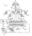
- FIG. 1is a schematic representation of a modular proportioning foam system formed in accordance with the present invention.
- FIG. 2is a graphical representation of the performance characteristics of a rotary gear pump used in connection with the present invention.
- modular proportioning foam system 1operates in connection with a firefighting apparatus, which may comprise a vehicle such as a conventional fire truck, fire boat or the like, or may be a part of a larger system or a stationary system such as a portion of the infrastructure of a building, ship, or airplane.
- a firefighting apparatuswhich may comprise a vehicle such as a conventional fire truck, fire boat or the like, or may be a part of a larger system or a stationary system such as a portion of the infrastructure of a building, ship, or airplane.
- modular proportioning foam system 1comprises a power source 10 , a foamant delivery assembly 15 , a water delivery assembly 20 , and a control system 25 .
- power source 10 in this embodimentprovides motive force, via hydraulic fluid, for operation of various pumps utilized in modular proportioning foam system 1 .
- Power source 10is of a type conventionally provided on fire trucks and the like, and includes a hydraulic pump 28 operatively interconnected with the transmission 30 of the vehicle engine, or to an auxiliary engine, or to another source of motive force 32 such as an electric motor drive or the like.
- Hydraulic pump 28is in regulated flow communication with hydraulic fluid reservoir 35 , and provides a flow of hydraulic fluid under pressure. Drain valve 37 is placed in the line therebetween.
- the hydraulic flow and the pressure thereofare provided by a variable displacement pump, such as the Mannesmann Rexroth series A10V0.
- Power source 10is operatively connected to a hydraulic manifold 40 , so as to provide a flow of hydraulic fluid under pressure, via a proportional hydraulic flow valve 43 , to foamant delivery assembly 15 and thereby conveying motive power from the power take off or other source.
- a proportional hydraulic flow control valvethat has been found to provide adequate results is the EPV series valve manufactured by the Vickres Company.
- Proportional hydraulic flow valve 43may be operated as an output element of a feed-back loop, that monitors the flow rate and pressure of the water in order to control the foamant flow, and may be controlled by an operator through control system 25 .
- Control system 25is based on a conventional microprocessor and includes a programmed processor coupled to inputs including sensing and control devices, computational or logical means, a memory, and outputs including control displays 27 that are accessible to the operator of the firefighting apparatus.
- Foamant delivery assembly 15comprises at least one foamant concentrate storage tank 50 , a header manifold 53 , a fixed displacement hydraulic motor 56 , a foamant pump 59 , and a foamant injection check valve 62 .
- Foamant concentrate storage tank 50is arranged in regulated flow communication with header manifold 53 , via valve 66 , so as to provide liquid concentrate foamant to header manifold 53 . It will be understood that a plurality of tanks 50 may be included so that various foamants can be used as appropriate.
- Hydraulic motor 56is arranged in regulated flow communication with hydraulic manifold 40 , and proportional flow hydraulic flow valve 43 , from which it is provided with pressurized hydraulic fluid for sustained operation.
- a fixed displacement hydraulic motorthat has been found to provide adequate results is the model A2FM manufactured by the Mannesmann Rexroth Company.
- Foamant pump 59advantageously comprises a rotary gear pump, such as the model 20 manufactured by the Edward Company.
- Foamant pump 59preferably is capable of operation in the relatively wide range from approximately 200 to 3600 revolutions per minute (rpm), to accommodate corresponding breadth in the range of control for the water flow between approximately 5% and 100% of its maximum capacity.
- At least one foamant pump 59is arranged in flow communication with header manifold 53 , from which it draws foamant during operation, and with a foamant conduit 63 .
- a plurality of foamant pumps 59 and foamant conduits 63may be interconnected to header manifold 53 .
- a speed sensor 64is interconnected with each foamant pump 59 , and is arranged to provide an electrical signal indicative of the speed of foamant pump 59 as an input to control system 25 .
- a Hall-effect type rpm sensormay be used with good effect.
- Foamant injection check valve 62is operatively interconnected to a portion of foamant conduit 63 , adjacent to the intersection between foamant conduit 63 and water delivery assembly 20 .
- Water delivery assembly 20comprises a water pump 70 , a discharge manifold 73 , a discharge flow meter 76 , a discharge flow control valve 79 , and a pressure transducer 80 .
- water pump 70is in regulated flow communication with a source of water, e.g., a holding tank, lagoon, hydrant, or the like, and is preferably a centrifugal pump, such as the ones manufactured by either Hale Company or Waterous Company, which are well known in the art.
- water pump 70has a capacity in the range from approximately 40 to 3000 or more gallons per minute (gpm). It will be understood that a plurality of water pumps 70 , likewise may be utilized with the present invention.
- discharge manifold 73forms a part of water pump 70 .
- Discharge manifold 73is interconnected in flow communication with a conduit 82 which is in flow communication with a discharge fixture (i.e., a conventional hose and nozzle, not shown).
- Conduit 82is operatively coupled to a discharge flow meter 76 , discharge flow control valve 79 , pressure transducer 80 , and foamant injection check valve 62 .
- this arrangementallows for the direct measurement of both the water pressure and foam pressure at the specific location along conduit 82 where liquid foamant concentrate is introduced into the flow of water from discharge manifold 73 .
- Pressure transducer 80is positioned within the wall of conduit 82 , and is preferably a ceramic capacitive type pressure transducer, where a diaphragm and substrate form the basic sensing element of a variable capacitor that is proportional to the applied pressure.
- This type of sensoris also known as a ratiometric pressure transducer with an excitation voltage of about 5 volts dc.
- the operating temperatureis in the range from about ⁇ 40 degrees centigrade to about +125 degrees centigrade, and with an accuracy of about +/ ⁇ 0.5% of the maximum voltage span.
- a plurality of conduitseach comprising an operative interconnection to a discharge flow meter 76 , a discharge flow control valve 79 , a pressure transducer 80 , and a foamant injection valve 62 may be provided in connection with the present invention.
- the inventionmay include, for example, a number of different discharge conduits to which hoses of different diameters might be coupled, via fittings at different locations around the fire truck. Each includes the necessary water and foamant drive and sensing arrangements to apply the invention to each of such conduits.
- the modular proportioning foam system 1 of the inventionoperates to control foamant introduction into a water stream as follows.
- an on/off switch positioned on a control panelis left in the “off” mode, and proportional hydraulic flow valve 43 is completely closed.
- Foamant injection check valve 62which is down stream of foamant pump 59 , ensures that no water will backflow to foamant pump 59 or foamant concentrate storage tank 50 .
- the on/off switch associated with that discharge port on display/controller 27is put in the “on” mode.
- the operatorcan select the desired percent of foamant injection, based upon the type of foam being used and the application desired.
- the typical range available to the operator for selectiongenerally is from about 0.1% to about 10%. This selection range of percentages can be uniquely chosen for each discharge port available. It is an important aspect of the invention that the predetermined selected proportion of foam is accurately controlled and maintained.
- the controllerreads the water flow sensed by flow meter 76 , the water/foam pressure sensed by pressure transducer 80 , and the percent concentration of foamant, to determine the required foam concentrate flow.
- proportional hydraulic flow valve 43is opened or closed until the speed that corresponds to the required flow of foam, at the operating pressure is reached.
- the water flow and pressureare monitored on a regular frequency in order to adjust foamant pump speed for any change in values, or any change in values (e.g., water pressure or water flow rate made by the operator to the desired foamant percent concentration.
- the foam output pressurecauses foamant injection check valve 62 to open, and liquid foamant concentrate flows into the water downstream of a discharge valve.
- Foamant pump 59is also responsive to any changes in the water/foamant flow made by a nobleman at the end of a discharge hose. When the nozzle is closed, a water flow sensor will indicate “no flow” and close proportional hydraulic flow valve 43 , stopping foamant pump 59 . As the discharge nozzle is opened or otherwise varied to any point between positions at which the flow may be fully throttled or opened completely, flow meter 76 and pressure transducer 80 sense the relative changes in flow and pressure, and provide corresponding signals to control system 25 so as to maintain the required foamant pump speed.
- the inventionprovides a signal to control system 25 that represents a measure of the discharge water pressure.
- the discharge pressure signalmay be read directly on the discharge line display/controller 27 , which fulfills a National Fire Prevention Assn. (NFPA) requirement for the pump panel.
- NFPANational Fire Prevention Assn.
- the water pressureis effectively equal to the foamant pump discharge pressure at this same location, namely adjacent to the pressure sensor and foam injection point. With this equality in pressure known, using both the foam pump speed and known foam discharge pressure gives excellent accuracy over the entire operating range of foam pump 59 .
- FIG. 2demonstrates the relationship of speed and flow in pump performance curves.
- the performance parameters in the embodiment shownsubstantially demonstrate a linear relationship (equal slopes) of flow versus speed, with different offsets at different pressures.
- the performance parameterscan be encoded into a matrix or lookup table accessible from controller/display 27 . Alternatively the slope and offset can be encoded and used to calculate operational parameters at a point on the curves, using the microprocessor controller.
- the performance parametersas thus accessibly stored, allow the use of the measured foamant pump speed and foamant pump pressure to predict the actual foam flow with a high degree of accuracy.
- the systemis responsive to a signal representative of water flow and both a foam pump speed signal and a foam pump output pressure signal which is equal to the water pressure measured via pressure transducer 80 .
- the inventionuses both the rotary gear foam pump speed and the outlet pressure to predict the foam flow. This is accomplished through a “look-up” table in display/controller 27 , similar to the data shown in FIG. 2 .
Landscapes
- Engineering & Computer Science (AREA)
- Physics & Mathematics (AREA)
- General Physics & Mathematics (AREA)
- Automation & Control Theory (AREA)
- Health & Medical Sciences (AREA)
- Public Health (AREA)
- Business, Economics & Management (AREA)
- Emergency Management (AREA)
- Mechanical Engineering (AREA)
- General Engineering & Computer Science (AREA)
- Control Of Positive-Displacement Pumps (AREA)
Abstract
Description
Claims (16)
Priority Applications (1)
| Application Number | Priority Date | Filing Date | Title |
|---|---|---|---|
| US09/539,855US6454540B1 (en) | 2000-03-31 | 2000-03-31 | Modular balanced foam flow system |
Applications Claiming Priority (1)
| Application Number | Priority Date | Filing Date | Title |
|---|---|---|---|
| US09/539,855US6454540B1 (en) | 2000-03-31 | 2000-03-31 | Modular balanced foam flow system |
Publications (1)
| Publication Number | Publication Date |
|---|---|
| US6454540B1true US6454540B1 (en) | 2002-09-24 |
Family
ID=24152935
Family Applications (1)
| Application Number | Title | Priority Date | Filing Date |
|---|---|---|---|
| US09/539,855Expired - LifetimeUS6454540B1 (en) | 2000-03-31 | 2000-03-31 | Modular balanced foam flow system |
Country Status (1)
| Country | Link |
|---|---|
| US (1) | US6454540B1 (en) |
Cited By (33)
| Publication number | Priority date | Publication date | Assignee | Title |
|---|---|---|---|---|
| US20030163228A1 (en)* | 1999-07-30 | 2003-08-28 | Oshkosh Truck Corporation | Turret targeting system and method for a fire fighting vehicle |
| US20030163230A1 (en)* | 1999-07-30 | 2003-08-28 | Oshkosh Truck Corporation | Turret operator interface system and method for a fire fighting vehicle |
| US20030171854A1 (en)* | 1999-07-30 | 2003-09-11 | Oshkosh Truck Corporation | Turret deployment system and method for a fire fighting vehicle |
| WO2003076060A1 (en)* | 2002-03-06 | 2003-09-18 | Kidde Fire Fighting, Inc. | Fire suppression apparatus mixing foam and water and method of the same |
| US20030194326A1 (en)* | 2002-04-12 | 2003-10-16 | Bettenhausen Craig A. | Electronic trim for a variable delivery pump in a hydraulic system for an engine |
| US6684959B1 (en) | 2002-08-02 | 2004-02-03 | Pierce Manufacturing Inc. | Foam concentrate proportioning system and methods for rescue and fire fighting vehicles |
| US20040069865A1 (en)* | 2002-02-28 | 2004-04-15 | Oshkosh Truck Corporation | Turret positioning system and method for a fire fighting vehicle |
| US6725940B1 (en)* | 2000-05-10 | 2004-04-27 | Pierce Manufacturing Inc. | Foam additive supply system for rescue and fire fighting vehicles |
| US20040136832A1 (en)* | 2002-11-07 | 2004-07-15 | Hammonds Carl L. | Fluid powered additive injection system |
| US20050045345A1 (en)* | 2003-08-29 | 2005-03-03 | Hypro Corporation | High flow foam system for fire fighting applications |
| US20050155776A1 (en)* | 2002-09-20 | 2005-07-21 | Hypro Corporation | Fire fighting foam injection system with auto-start feature |
| US20060243324A1 (en)* | 2005-04-29 | 2006-11-02 | Pierce Manufacturing Inc. | Automatic start additive injection system for fire-fighting vehicles |
| US20070088469A1 (en)* | 2005-10-04 | 2007-04-19 | Oshkosh Truck Corporation | Vehicle control system and method |
| US20080135263A1 (en)* | 2005-02-04 | 2008-06-12 | Graham Douglas Millard | Fire Protection Induction System |
| US20080185159A1 (en)* | 2007-02-06 | 2008-08-07 | City Of Chicago | Foam fire suppression apparatus |
| US20090095492A1 (en)* | 2007-10-12 | 2009-04-16 | Fm Global Technologies | Fire fighting foam dispensing system and related method |
| US20100065286A1 (en)* | 2008-04-21 | 2010-03-18 | Hosfield Robert L | Ultra-High Pressure Fire-Fighting System |
| US7711460B2 (en) | 2001-01-31 | 2010-05-04 | Oshkosh Corporation | Control system and method for electric vehicle |
| US7835838B2 (en) | 1999-07-30 | 2010-11-16 | Oshkosh Corporation | Concrete placement vehicle control system and method |
| US7997348B2 (en) | 2008-01-03 | 2011-08-16 | Sta-Rite Industries, Llc | Foam proportioning system with low-end controller |
| US20130105010A1 (en)* | 2011-10-28 | 2013-05-02 | Jnt Link, Llc | Automatic fire pump control system and method |
| US20140050592A1 (en)* | 2012-08-16 | 2014-02-20 | Getrag Getriebe- Und Zahnradfabrik Hermann Hagenmeyer Gmbh & Cie Kg | Temperature detection method in a hydraulic arrangement |
| DE102013201299A1 (en)* | 2013-01-28 | 2014-07-31 | Matthias Deufert | Valve for integration in fire fighting water system, comprises a sensor device which is arranged adjacent to the volume measuring device for detecting the operating state of the valve |
| US9149671B2 (en) | 2010-03-18 | 2015-10-06 | Fire Research Corp. | Compact fire-extinguishing system with high-pressure foam proportioning system |
| US9333379B2 (en) | 2012-01-27 | 2016-05-10 | Simplex Manufacturing Co. | Aerial fire suppression system |
| US9427609B2 (en) | 2012-12-05 | 2016-08-30 | Icl Performance Products Lp | Method and system for diluting multiple chemical concentrates and dispersing resultant solutions utilizing a single portable source |
| US9597646B2 (en) | 2012-12-05 | 2017-03-21 | Icl Performance Products Lp | Method and system for diluting multiple chemical concentrates and dispersing resultant solutions utilizing a single portable source |
| US9718039B2 (en) | 2014-10-02 | 2017-08-01 | Hammonds Technical Services, Inc. | Apparatus for mixing and blending of an additive material into a fluid and method |
| US10406390B2 (en) | 2016-08-09 | 2019-09-10 | Simplex Manufacturing Co. | Aerial fire suppression system |
| CN113236272A (en)* | 2021-05-31 | 2021-08-10 | 徐工集团凯宫重工南京股份有限公司 | Hydraulic control system for foam system, foam system and shield tunneling machine |
| US20220143439A1 (en)* | 2019-04-24 | 2022-05-12 | Tyco Fire Products Lp | Integrated firefighting fluid supply mechanism and methods thereof |
| US11619526B2 (en)* | 2019-04-11 | 2023-04-04 | Hale Products, Inc. | Fire truck pump flow prediction system |
| CN119215366A (en)* | 2024-10-10 | 2024-12-31 | 湖南中联重科应急装备有限公司 | Fire fighting system assembly and foam ratio control method thereof, fire fighting equipment |
Citations (19)
| Publication number | Priority date | Publication date | Assignee | Title |
|---|---|---|---|---|
| US4189005A (en)* | 1977-11-07 | 1980-02-19 | Mcloughlin John | Fire truck control means |
| US4417601A (en) | 1980-12-19 | 1983-11-29 | National Foam Systems, Inc. | Variable proportioning valve for balanced pressure proportioning systems, and system containing the valve |
| US4436487A (en) | 1982-06-29 | 1984-03-13 | Enterra Corporation | Foam liquid concentrate supply system |
| US4474680A (en)* | 1983-03-14 | 1984-10-02 | Valerin Technologies Limited | Foam generating apparatus and method |
| US4899825A (en)* | 1987-06-25 | 1990-02-13 | Snamprogetti, S.P.A. | Continuous mixing device, particulary suitable for preparing aqueous solutions of foam extinguisher for fire-fighting systems |
| US5174383A (en) | 1988-09-08 | 1992-12-29 | Hypro Corporation | Apparatus and method for controlling the introduction of chemical foamant into water stream in fire-fighting equipment |
| US5218988A (en) | 1991-09-25 | 1993-06-15 | Beta Technology, Inc. | Liquid feed system |
| US5232052A (en) | 1993-02-09 | 1993-08-03 | Hypro Corporation | Apparatus and method for controlling the introduction of chemical foamant into a water stream in fire-fighting equipment |
| US5284174A (en) | 1992-08-18 | 1994-02-08 | Chubb National Foam, Inc. | System and method for producing and maintaining predetermined proportionate mixtures of fluids |
| US5291951A (en)* | 1992-12-28 | 1994-03-08 | Utah La Grange, Inc. | Compressed air foam pump apparatus |
| US5411100A (en) | 1992-10-01 | 1995-05-02 | Hale Fire Pump Company | Compressed air foam system |
| US5427181A (en) | 1993-06-14 | 1995-06-27 | Hale Fire Pump Company | Mixer for compressed air foam system |
| US5494112A (en) | 1993-10-29 | 1996-02-27 | Hypro Corporation | System for introduction of concentrated liquid chemical foamant into a water stream for fighting fires |
| US5680329A (en)* | 1996-07-05 | 1997-10-21 | Lloyd; Steven J. | Fire protection code compliance verification system and method |
| US5727933A (en) | 1995-12-20 | 1998-03-17 | Hale Fire Pump Company | Pump and flow sensor combination |
| US5764463A (en) | 1996-09-06 | 1998-06-09 | Hypro Corporation | Current limiting circuit and electronic fuse for use in foam injection fire fighting systems |
| US5803596A (en)* | 1996-05-17 | 1998-09-08 | Stephens; Patrick J. | Method and apparatus for high capacity production of finished aqueous foam with continuously adjustable proportioning |
| US5979564A (en)* | 1995-04-24 | 1999-11-09 | Willaims Fire & Hazard Control, Inc. | Fluid additive supply system for fire fighting mechanisms |
| US6009953A (en)* | 1997-02-25 | 2000-01-04 | Hale Products, Inc. | Foam pump system for firefighting apparatus |
- 2000
- 2000-03-31USUS09/539,855patent/US6454540B1/ennot_activeExpired - Lifetime
Patent Citations (21)
| Publication number | Priority date | Publication date | Assignee | Title |
|---|---|---|---|---|
| US4189005A (en)* | 1977-11-07 | 1980-02-19 | Mcloughlin John | Fire truck control means |
| US4417601A (en) | 1980-12-19 | 1983-11-29 | National Foam Systems, Inc. | Variable proportioning valve for balanced pressure proportioning systems, and system containing the valve |
| US4436487A (en) | 1982-06-29 | 1984-03-13 | Enterra Corporation | Foam liquid concentrate supply system |
| US4474680A (en)* | 1983-03-14 | 1984-10-02 | Valerin Technologies Limited | Foam generating apparatus and method |
| US4899825A (en)* | 1987-06-25 | 1990-02-13 | Snamprogetti, S.P.A. | Continuous mixing device, particulary suitable for preparing aqueous solutions of foam extinguisher for fire-fighting systems |
| US5174383A (en) | 1988-09-08 | 1992-12-29 | Hypro Corporation | Apparatus and method for controlling the introduction of chemical foamant into water stream in fire-fighting equipment |
| US5218988A (en) | 1991-09-25 | 1993-06-15 | Beta Technology, Inc. | Liquid feed system |
| US5284174A (en) | 1992-08-18 | 1994-02-08 | Chubb National Foam, Inc. | System and method for producing and maintaining predetermined proportionate mixtures of fluids |
| US5411100A (en) | 1992-10-01 | 1995-05-02 | Hale Fire Pump Company | Compressed air foam system |
| US5291951A (en)* | 1992-12-28 | 1994-03-08 | Utah La Grange, Inc. | Compressed air foam pump apparatus |
| US5313548A (en) | 1993-02-09 | 1994-05-17 | Hypro Corporation | Direct current motor speed controller |
| US5232052A (en) | 1993-02-09 | 1993-08-03 | Hypro Corporation | Apparatus and method for controlling the introduction of chemical foamant into a water stream in fire-fighting equipment |
| USRE35362E (en) | 1993-02-09 | 1996-10-29 | Hypro Corporation | Apparatus and method for controlling the introduction of chemical foamant into a water stream in fire-fighting equipment |
| US5427181A (en) | 1993-06-14 | 1995-06-27 | Hale Fire Pump Company | Mixer for compressed air foam system |
| US5494112A (en) | 1993-10-29 | 1996-02-27 | Hypro Corporation | System for introduction of concentrated liquid chemical foamant into a water stream for fighting fires |
| US5979564A (en)* | 1995-04-24 | 1999-11-09 | Willaims Fire & Hazard Control, Inc. | Fluid additive supply system for fire fighting mechanisms |
| US5727933A (en) | 1995-12-20 | 1998-03-17 | Hale Fire Pump Company | Pump and flow sensor combination |
| US5803596A (en)* | 1996-05-17 | 1998-09-08 | Stephens; Patrick J. | Method and apparatus for high capacity production of finished aqueous foam with continuously adjustable proportioning |
| US5680329A (en)* | 1996-07-05 | 1997-10-21 | Lloyd; Steven J. | Fire protection code compliance verification system and method |
| US5764463A (en) | 1996-09-06 | 1998-06-09 | Hypro Corporation | Current limiting circuit and electronic fuse for use in foam injection fire fighting systems |
| US6009953A (en)* | 1997-02-25 | 2000-01-04 | Hale Products, Inc. | Foam pump system for firefighting apparatus |
Cited By (53)
| Publication number | Priority date | Publication date | Assignee | Title |
|---|---|---|---|---|
| US20030163230A1 (en)* | 1999-07-30 | 2003-08-28 | Oshkosh Truck Corporation | Turret operator interface system and method for a fire fighting vehicle |
| US20030171854A1 (en)* | 1999-07-30 | 2003-09-11 | Oshkosh Truck Corporation | Turret deployment system and method for a fire fighting vehicle |
| US7835838B2 (en) | 1999-07-30 | 2010-11-16 | Oshkosh Corporation | Concrete placement vehicle control system and method |
| US20030163228A1 (en)* | 1999-07-30 | 2003-08-28 | Oshkosh Truck Corporation | Turret targeting system and method for a fire fighting vehicle |
| US7184862B2 (en) | 1999-07-30 | 2007-02-27 | Oshkosh Truck Corporation | Turret targeting system and method for a fire fighting vehicle |
| US7162332B2 (en) | 1999-07-30 | 2007-01-09 | Oshkosh Truck Corporation | Turret deployment system and method for a fire fighting vehicle |
| US7127331B2 (en)* | 1999-07-30 | 2006-10-24 | Oshkosh Truck Corporation | Turret operator interface system and method for a fire fighting vehicle |
| US6725940B1 (en)* | 2000-05-10 | 2004-04-27 | Pierce Manufacturing Inc. | Foam additive supply system for rescue and fire fighting vehicles |
| US7711460B2 (en) | 2001-01-31 | 2010-05-04 | Oshkosh Corporation | Control system and method for electric vehicle |
| US7107129B2 (en) | 2002-02-28 | 2006-09-12 | Oshkosh Truck Corporation | Turret positioning system and method for a fire fighting vehicle |
| US7274976B2 (en) | 2002-02-28 | 2007-09-25 | Oshkosh Truck Corporation | Turret positioning system and method for a vehicle |
| US20040069865A1 (en)* | 2002-02-28 | 2004-04-15 | Oshkosh Truck Corporation | Turret positioning system and method for a fire fighting vehicle |
| US20040050556A1 (en)* | 2002-03-06 | 2004-03-18 | Kidde Fire Fighting, Inc. | Fire suppression apparatus mixing foam and water and method of the same |
| WO2003076060A1 (en)* | 2002-03-06 | 2003-09-18 | Kidde Fire Fighting, Inc. | Fire suppression apparatus mixing foam and water and method of the same |
| US6986646B2 (en)* | 2002-04-12 | 2006-01-17 | Caterpillar Inc. | Electronic trim for a variable delivery pump in a hydraulic system for an engine |
| US20030194326A1 (en)* | 2002-04-12 | 2003-10-16 | Bettenhausen Craig A. | Electronic trim for a variable delivery pump in a hydraulic system for an engine |
| WO2004012819A1 (en)* | 2002-08-02 | 2004-02-12 | Pierce Manufacturing Inc. | Foam concentrate proportioning system and methods for rescue and fire fighting vehicles |
| US6684959B1 (en) | 2002-08-02 | 2004-02-03 | Pierce Manufacturing Inc. | Foam concentrate proportioning system and methods for rescue and fire fighting vehicles |
| US20050155776A1 (en)* | 2002-09-20 | 2005-07-21 | Hypro Corporation | Fire fighting foam injection system with auto-start feature |
| US7318483B2 (en)* | 2002-09-20 | 2008-01-15 | Hypro, Llc | Fire fighting foam injection system with auto-start feature |
| US7066353B2 (en) | 2002-11-07 | 2006-06-27 | Hammonds Carl L | Fluid powered additive injection system |
| US20040136832A1 (en)* | 2002-11-07 | 2004-07-15 | Hammonds Carl L. | Fluid powered additive injection system |
| WO2005021099A3 (en)* | 2003-08-29 | 2005-06-30 | Hypro Corp | High flow foam system for fire fighting applications |
| US20050045345A1 (en)* | 2003-08-29 | 2005-03-03 | Hypro Corporation | High flow foam system for fire fighting applications |
| US6886639B2 (en)* | 2003-08-29 | 2005-05-03 | Hypro Corporation | High flow foam system for fire fighting applications |
| US20080135263A1 (en)* | 2005-02-04 | 2008-06-12 | Graham Douglas Millard | Fire Protection Induction System |
| US20060243324A1 (en)* | 2005-04-29 | 2006-11-02 | Pierce Manufacturing Inc. | Automatic start additive injection system for fire-fighting vehicles |
| US20070088469A1 (en)* | 2005-10-04 | 2007-04-19 | Oshkosh Truck Corporation | Vehicle control system and method |
| US20080185159A1 (en)* | 2007-02-06 | 2008-08-07 | City Of Chicago | Foam fire suppression apparatus |
| US20090095492A1 (en)* | 2007-10-12 | 2009-04-16 | Fm Global Technologies | Fire fighting foam dispensing system and related method |
| US7703543B2 (en) | 2007-10-12 | 2010-04-27 | Fm Global Technologies | Fire fighting foam dispensing system and related method |
| US7997348B2 (en) | 2008-01-03 | 2011-08-16 | Sta-Rite Industries, Llc | Foam proportioning system with low-end controller |
| US20100065286A1 (en)* | 2008-04-21 | 2010-03-18 | Hosfield Robert L | Ultra-High Pressure Fire-Fighting System |
| US9149671B2 (en) | 2010-03-18 | 2015-10-06 | Fire Research Corp. | Compact fire-extinguishing system with high-pressure foam proportioning system |
| US20130105010A1 (en)* | 2011-10-28 | 2013-05-02 | Jnt Link, Llc | Automatic fire pump control system and method |
| US9333379B2 (en) | 2012-01-27 | 2016-05-10 | Simplex Manufacturing Co. | Aerial fire suppression system |
| US11439852B2 (en) | 2012-01-27 | 2022-09-13 | Simplex Manufacturing Co. | Aerial fire suppression system |
| US9981150B2 (en) | 2012-01-27 | 2018-05-29 | Simplex Manufacturing Co. | Aerial fire suppression system |
| US10369392B2 (en) | 2012-01-27 | 2019-08-06 | Simplex Manufacturing Co. | Aerial fire suppression system |
| US20140050592A1 (en)* | 2012-08-16 | 2014-02-20 | Getrag Getriebe- Und Zahnradfabrik Hermann Hagenmeyer Gmbh & Cie Kg | Temperature detection method in a hydraulic arrangement |
| US9759205B2 (en)* | 2012-08-16 | 2017-09-12 | GETRAG Getriebe—und Zahnradfabrik Hermann Hagenmeyer GmbH & Cie KG | Temperature detection method in a hydraulic arrangement |
| US9427609B2 (en) | 2012-12-05 | 2016-08-30 | Icl Performance Products Lp | Method and system for diluting multiple chemical concentrates and dispersing resultant solutions utilizing a single portable source |
| US9597646B2 (en) | 2012-12-05 | 2017-03-21 | Icl Performance Products Lp | Method and system for diluting multiple chemical concentrates and dispersing resultant solutions utilizing a single portable source |
| US10166419B2 (en) | 2012-12-05 | 2019-01-01 | Perimeter Solutions Lp | Method and system for diluting multiple chemical concentrates and dispersing resultant solutions utilizing a single portable source |
| DE102013201299A1 (en)* | 2013-01-28 | 2014-07-31 | Matthias Deufert | Valve for integration in fire fighting water system, comprises a sensor device which is arranged adjacent to the volume measuring device for detecting the operating state of the valve |
| DE102013201299B4 (en)* | 2013-01-28 | 2016-09-29 | Matthias Deufert | Fitting for extinguishing water system |
| US9718039B2 (en) | 2014-10-02 | 2017-08-01 | Hammonds Technical Services, Inc. | Apparatus for mixing and blending of an additive material into a fluid and method |
| US10406390B2 (en) | 2016-08-09 | 2019-09-10 | Simplex Manufacturing Co. | Aerial fire suppression system |
| US11717711B2 (en) | 2016-08-09 | 2023-08-08 | Simplex Manufacturing Co. | Aerial fire suppression system |
| US11619526B2 (en)* | 2019-04-11 | 2023-04-04 | Hale Products, Inc. | Fire truck pump flow prediction system |
| US20220143439A1 (en)* | 2019-04-24 | 2022-05-12 | Tyco Fire Products Lp | Integrated firefighting fluid supply mechanism and methods thereof |
| CN113236272A (en)* | 2021-05-31 | 2021-08-10 | 徐工集团凯宫重工南京股份有限公司 | Hydraulic control system for foam system, foam system and shield tunneling machine |
| CN119215366A (en)* | 2024-10-10 | 2024-12-31 | 湖南中联重科应急装备有限公司 | Fire fighting system assembly and foam ratio control method thereof, fire fighting equipment |
Similar Documents
| Publication | Publication Date | Title |
|---|---|---|
| US6454540B1 (en) | Modular balanced foam flow system | |
| US4324294A (en) | Chemical injection control system for fire fighting | |
| US6220747B1 (en) | Proportional pump system for viscous fluids | |
| US7878703B2 (en) | Electronically controlled direct injection foam delivery system with temperature compensation | |
| US8517696B2 (en) | Comprehensive control system for mobile pumping apparatus | |
| US5979564A (en) | Fluid additive supply system for fire fighting mechanisms | |
| US4246969A (en) | Chemical injection system for fire fighting | |
| US5803596A (en) | Method and apparatus for high capacity production of finished aqueous foam with continuously adjustable proportioning | |
| US5411100A (en) | Compressed air foam system | |
| JP2668709B2 (en) | A device for continuously preparing solutions with variable flow rates and constant mixing ratio | |
| US6009953A (en) | Foam pump system for firefighting apparatus | |
| US5494112A (en) | System for introduction of concentrated liquid chemical foamant into a water stream for fighting fires | |
| US5174383A (en) | Apparatus and method for controlling the introduction of chemical foamant into water stream in fire-fighting equipment | |
| EP2095848B1 (en) | Hybrid foam proportioning system | |
| US5921263A (en) | Fuel dispensing system using a common meter and octane sensing | |
| US20040177975A1 (en) | Compressed air foam pumping system | |
| US20050222287A1 (en) | Electronically controlled direct injection foam delivery system and method of regulating flow of foam into water stream based on conductivity measure | |
| JP2009202921A (en) | Fuel mixing apparatus | |
| JP4237473B2 (en) | Chemical injection method and apparatus | |
| CN102549517A (en) | Systems for Filling Liners | |
| JPH08215335A (en) | Automatic bubble fire extinguishing solution injection device | |
| JP3067609B2 (en) | Liquid mixing equipment | |
| US6009761A (en) | Multiproduct fuel dispenser using ultrasonic metering | |
| JP3701181B2 (en) | Multi-component mixed pressure feeder | |
| RU195411U1 (en) | Automatic foaming agent dosing |
Legal Events
| Date | Code | Title | Description |
|---|---|---|---|
| AS | Assignment | Owner name:KOVATCH MOBILE EQUIPMENT CORP., PENNSYLVANIA Free format text:ASSIGNMENT OF ASSIGNORS INTEREST;ASSIGNORS:TEREFINKO, JOHN M.;TAYLOR, RICHARD;REEL/FRAME:012860/0554 Effective date:20020418 | |
| STCF | Information on status: patent grant | Free format text:PATENTED CASE | |
| FPAY | Fee payment | Year of fee payment:4 | |
| FPAY | Fee payment | Year of fee payment:8 | |
| REMI | Maintenance fee reminder mailed | ||
| FPAY | Fee payment | Year of fee payment:12 | |
| SULP | Surcharge for late payment | Year of fee payment:11 | |
| AS | Assignment | Owner name:DEUTSCHE BANK AG NEW YORK BRANCH, AS REVOLVING COL Free format text:GRANT OF SECURITY INTEREST IN PATENTS;ASSIGNOR:KOVATCH MOBILE EQUIPMENT CORP.;REEL/FRAME:038514/0230 Effective date:20160422 | |
| AS | Assignment | Owner name:COLLINS BUS CORPORATION, KANSAS Free format text:RELEASE BY SECURED PARTY;ASSIGNOR:DEUTSCHE BANK AG NEW YORK BRANCH;REEL/FRAME:042328/0987 Effective date:20170425 Owner name:E-ONE, INC., FLORIDA Free format text:RELEASE BY SECURED PARTY;ASSIGNOR:DEUTSCHE BANK AG NEW YORK BRANCH;REEL/FRAME:042328/0987 Effective date:20170425 Owner name:REV RECREATION GROUP, INC. (FORMERLY ALLIED RECREA Free format text:RELEASE BY SECURED PARTY;ASSIGNOR:DEUTSCHE BANK AG NEW YORK BRANCH;REEL/FRAME:042328/0987 Effective date:20170425 Owner name:KOVATCH MOBILE EQUIPMENT CORP., PENNSYLVANIA Free format text:RELEASE BY SECURED PARTY;ASSIGNOR:DEUTSCHE BANK AG NEW YORK BRANCH;REEL/FRAME:042328/0987 Effective date:20170425 Owner name:REV AMBULANCE GROUP ORLANDO, INC. (FORMERLY WHEELE Free format text:RELEASE BY SECURED PARTY;ASSIGNOR:DEUTSCHE BANK AG NEW YORK BRANCH;REEL/FRAME:042328/0987 Effective date:20170425 Owner name:HALCORE GROUP, INC., OHIO Free format text:RELEASE BY SECURED PARTY;ASSIGNOR:DEUTSCHE BANK AG NEW YORK BRANCH;REEL/FRAME:042328/0987 Effective date:20170425 Owner name:CAPACITY OF TEXAS, INC., WISCONSIN Free format text:RELEASE BY SECURED PARTY;ASSIGNOR:DEUTSCHE BANK AG NEW YORK BRANCH;REEL/FRAME:042328/0987 Effective date:20170425 Owner name:REV AMBULANCE GROUP ORLANDO, INC. (FORMERLY WHEELED COACH INDUSTRIES, INC.), FLORIDA Free format text:RELEASE BY SECURED PARTY;ASSIGNOR:DEUTSCHE BANK AG NEW YORK BRANCH;REEL/FRAME:042328/0987 Effective date:20170425 Owner name:REV RECREATION GROUP, INC. (FORMERLY ALLIED RECREATION GROUP, INC. (FORMERLY FLEETWOOD RV, INC.)), INDIANA Free format text:RELEASE BY SECURED PARTY;ASSIGNOR:DEUTSCHE BANK AG NEW YORK BRANCH;REEL/FRAME:042328/0987 Effective date:20170425 |