US6454000B1 - Cavity well positioning system and method - Google Patents
Cavity well positioning system and methodDownload PDFInfo
- Publication number
- US6454000B1 US6454000B1US09/696,338US69633800AUS6454000B1US 6454000 B1US6454000 B1US 6454000B1US 69633800 AUS69633800 AUS 69633800AUS 6454000 B1US6454000 B1US 6454000B1
- Authority
- US
- United States
- Prior art keywords
- cavity
- positioning device
- well bore
- subterranean
- cavity positioning
- Prior art date
- Legal status (The legal status is an assumption and is not a legal conclusion. Google has not performed a legal analysis and makes no representation as to the accuracy of the status listed.)
- Expired - Fee Related
Links
- 238000000034methodMethods0.000titleclaimsdescription36
- 230000007704transitionEffects0.000claimsabstractdescription10
- 239000012530fluidSubstances0.000claimsdescription34
- 239000003245coalSubstances0.000description92
- 238000005553drillingMethods0.000description51
- VNWKTOKETHGBQD-UHFFFAOYSA-NmethaneChemical compoundCVNWKTOKETHGBQD-UHFFFAOYSA-N0.000description30
- 238000005065miningMethods0.000description26
- XLYOFNOQVPJJNP-UHFFFAOYSA-NwaterSubstancesOXLYOFNOQVPJJNP-UHFFFAOYSA-N0.000description20
- 238000004519manufacturing processMethods0.000description18
- 230000015572biosynthetic processEffects0.000description17
- 238000005755formation reactionMethods0.000description17
- 238000010586diagramMethods0.000description11
- 230000002706hydrostatic effectEffects0.000description8
- 238000005520cutting processMethods0.000description7
- 230000008569processEffects0.000description6
- 238000005086pumpingMethods0.000description5
- 239000006260foamSubstances0.000description3
- 238000005259measurementMethods0.000description3
- 230000007246mechanismEffects0.000description3
- 238000005273aerationMethods0.000description2
- 238000007872degassingMethods0.000description2
- 230000005251gamma rayEffects0.000description2
- 229930195733hydrocarbonNatural products0.000description2
- 150000002430hydrocarbonsChemical class0.000description2
- 238000012986modificationMethods0.000description2
- 230000004048modificationEffects0.000description2
- 239000011148porous materialSubstances0.000description2
- 239000000654additiveSubstances0.000description1
- 230000002411adverseEffects0.000description1
- 238000011109contaminationMethods0.000description1
- 238000007796conventional methodMethods0.000description1
- 239000010779crude oilSubstances0.000description1
- 230000001934delayEffects0.000description1
- 230000003111delayed effectEffects0.000description1
- 238000013461designMethods0.000description1
- 238000011161developmentMethods0.000description1
- 230000009977dual effectEffects0.000description1
- 239000000428dustSubstances0.000description1
- 230000000694effectsEffects0.000description1
- 238000005516engineering processMethods0.000description1
- 238000000605extractionMethods0.000description1
- 210000003746featherAnatomy0.000description1
- 239000008398formation waterSubstances0.000description1
- 239000000446fuelSubstances0.000description1
- 238000011065in-situ storageMethods0.000description1
- 230000000977initiatory effectEffects0.000description1
- 229910052500inorganic mineralInorganic materials0.000description1
- 238000009434installationMethods0.000description1
- 230000007257malfunctionEffects0.000description1
- 239000000463materialSubstances0.000description1
- 238000013508migrationMethods0.000description1
- 230000005012migrationEffects0.000description1
- 239000011707mineralSubstances0.000description1
- 238000002360preparation methodMethods0.000description1
- 238000011084recoveryMethods0.000description1
- 239000011435rockSubstances0.000description1
- 238000000926separation methodMethods0.000description1
- 238000012876topographyMethods0.000description1
- 210000003462veinAnatomy0.000description1
Images


Classifications
- E—FIXED CONSTRUCTIONS
- E21—EARTH OR ROCK DRILLING; MINING
- E21B—EARTH OR ROCK DRILLING; OBTAINING OIL, GAS, WATER, SOLUBLE OR MELTABLE MATERIALS OR A SLURRY OF MINERALS FROM WELLS
- E21B43/00—Methods or apparatus for obtaining oil, gas, water, soluble or meltable materials or a slurry of minerals from wells
- E21B43/006—Production of coal-bed methane
- E—FIXED CONSTRUCTIONS
- E21—EARTH OR ROCK DRILLING; MINING
- E21B—EARTH OR ROCK DRILLING; OBTAINING OIL, GAS, WATER, SOLUBLE OR MELTABLE MATERIALS OR A SLURRY OF MINERALS FROM WELLS
- E21B47/00—Survey of boreholes or wells
- E21B47/09—Locating or determining the position of objects in boreholes or wells, e.g. the position of an extending arm; Identifying the free or blocked portions of pipes
Definitions
- the present inventionrelates generally to systems and methods for the recovery of subterranean resources and, more particularly, to a cavity well positioning system and method.
- coal seamsare often associated with subterranean water, which must be drained from the coal seam in order to produce the methane.
- a further problem for surface production of gas from coal seamsis the difficulty presented by under balanced drilling conditions caused by the porousness of the coal seam.
- drilling fluidis used to remove cuttings from the well bore to the surface.
- the drilling fluidexerts a hydrostatic pressure on the formation which, if it exceeds the hydrostatic pressure of the formation, can result in a loss of drilling fluid into the formation. This results in entrainment of drilling finds in the formation, which tends to plug the pores, cracks, and fractures that are needed to produce the gas.
- the present inventionprovides a cavity well positioning system and method for positioning down-hole pumps and equipment within a subterranean cavity that substantially eliminates or reduces the disadvantages and problems associated with previous systems and methods.
- the present inventionprovides a cavity well positioning system and method for efficiently positioning and removing down-hole equipment from within a subterranean cavity 20 without requiring additional locking, unlocking or alignment tools to facilitate the positioning and withdrawal of down-hole equipment.
- a subterranean cavity positioning systemincludes a down-hole device and a cavity positioning device rotatably coupled to a well portion of the down-hole device.
- the cavity positioning deviceincludes a counterbalance portion operable to automatically rotate the cavity positioning device from a retracted position to an extended position as the cavity positioning device transitions from a well bore into the subterranean cavity.
- the counterbalance portionis also operable to align the cavity positioning device with the well bore as the down-hole device is withdrawn from the subterranean cavity.
- a method for automatically positioning and retrieving down-hole equipment in a subterranean cavityincludes providing a cavity positioning device coupled to a well bore portion of a down-hole device and deploying the down-hole device and the cavity positioning device into a well bore.
- the cavity positioning deviceis disposed in a retracted position relative to the well bore.
- the methodalso includes running the down-hole device and the cavity positioning device downwardly within the well bore to the cavity.
- the cavity positioning deviceautomatically transitions to an extended position relative to the well bore in the cavity.
- the methodfurther includes positioning the down-hole device at a predefined location in the cavity by contacting a portion of the cavity with the cavity positioning device.
- a rotatable cavity positioning deviceis configured to retract for transport in a well bore and to extend within a down-hole cavity to optimally position the equipment within the cavity. This allows down-hole equipment to be easily positioned and secured within the cavity.
- FIG. 1is a cross-sectional diagram illustrating formation of a horizontal drainage pattern in a subterranean zone through an articulated surface well intersecting a vertical cavity well in accordance with one embodiment of the present invention
- FIG. 2is a cross-sectional diagram illustrating formation of the horizontal drainage pattern in the subterranean zone through the articulated surface well intersecting the vertical cavity well in accordance with another embodiment of the present invention
- FIG. 3is a cross-sectional diagram illustrating production of fluids from a horizontal draining pattern in a subterranean zone through a vertical well bore in accordance with one embodiment of the present invention
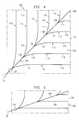
- FIG. 4is a top plan diagram illustrating a pinnate drainage pattern for accessing deposits in a subterranean zone in accordance with one embodiment of the present invention
- FIG. 5is a top plan diagram illustrating a pinnate drainage pattern for accessing deposits in a subterranean zone in accordance with another embodiment of the present invention
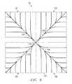
- FIG. 6is a top plan diagram illustrating a quadrilateral pinnate drainage pattern for accessing deposits in a subterranean zone in accordance with still another embodiment of the present invention
- FIG. 7is a top plan diagram illustrating the alignment of pinnate drainage patterns within panels of a coal seam for degasifying and preparing the coal seam for mining operations in accordance with one embodiment of the present invention
- FIG. 8is a flow diagram illustrating a method for preparing a coal seam for mining operations in accordance with one embodiment of the present invention
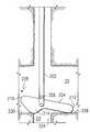
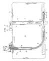
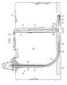
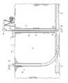
- FIGS. 9A-9Care cross-sectional diagrams illustrating a cavity well positioning system in accordance with an embodiment of the present invention.
- FIG. 1illustrates a cavity and articulated well combination for accessing a subterranean zone from the surface in accordance with one embodiment of the present invention.
- the subterranean zoneis a coal seam. It will be understood that other low pressure, ultra-low pressure, and low porosity subterranean zones can be similarly accessed using the dual well system of the present invention to remove and/or produce water, hydrocarbons and other fluids in the zone and to treat minerals in the zone prior to mining operations.
- a substantially vertical well bore 12extends from the surface 14 to a target coal seam 15 .
- the substantially vertical well bore 12intersects, penetrates and continues below the coal seam 15 .
- the substantially vertical well boreis lined with a suitable well casing 16 that terminates at or above the level of the coal seam 15 .
- the substantially vertical well bore 12is logged either during or after drilling in order to locate the exact vertical depth of the coal seam 15 .
- An enlarged diameter cavity 20is formed in the substantially vertical well bore 12 at the level of the coal seam 15 .
- the enlarged diameter cavity 20provides a junction for intersection of the substantially vertical well bore by articulated well bore used to form a substantially horizontal drainage pattern in the coal seam 15 .
- the enlarged diameter cavity 20also provides a collection point for fluids drained from the coal seam 15 during production operations.
- the enlarged diameter cavity 20has a radius of approximately eight feet and a vertical dimension which equals or exceeds the vertical dimension of the coal seam 15 .
- the enlarged diameter cavity 20is formed using suitable under-reaming techniques and equipment.
- a vertical portion of the substantially vertical well bore 12continues below the enlarged diameter cavity 20 to form a sump 22 for the cavity 20 .
- An articulated well bore 30extends from the surface 14 to the enlarged diameter cavity 20 of the substantially vertical well bore 12 .
- the articulated well bore 30includes a substantially vertical portion 32 , a substantially horizontal portion 34 , and a curved or radiused portion 36 interconnecting the vertical and horizontal portions 32 and 34 .
- the horizontal portion 34lies substantially in the horizontal plane of the coal seam 15 and intersects the large diameter cavity 20 of the substantially vertical well bore 12 .
- the articulated well bore 30is offset a sufficient distance from the substantially vertical well bore 12 at the surface 14 to permit the large radius curved section 36 and any desired horizontal section 34 to be drilled before intersecting the enlarged diameter cavity 20 .
- the articulated well bore 30is offset a distance of about 300 feet from the substantially vertical well bore 12 . This spacing minimizes the angle of the curved portion 36 to reduce friction in the bore 30 during drilling operations. As a result, reach of the articulated drill string drilled through the articulated well bore 30 is maximized.
- the articulated well bore 30is drilled using articulated drill string 40 that includes a suitable down-hole motor and bit 42 .
- a measurement while drilling (MWD) device 44is included in the articulated drill string 40 for controlling the orientation and direction of the well bore drilled by the motor and bit 42 .
- the substantially vertical portion 32 of the articulated well bore 30is lined with a suitable casing 38 .
- the substantially horizontal drainage pattern 50 and other such well boresinclude sloped, undulating, or other inclinations of the coal seam 15 or other subterranean zone.
- gamma ray logging tools and conventional measurement while drilling devicesmay be employed to control and direct the orientation of the drill bit to retain the drainage pattern 50 within the confines of the coal seam 15 and to provide substantially uniform coverage of a desired area within the coal seam 15 . Further information regarding the drainage pattern is described in more detail below in connection with FIGS. 4-7.
- drilling fluid or “mud”is pumped down the articulated drill string 40 and circulated out of the drill string 40 in the vicinity of the bit 42 , where it is used to scour the formation and to remove formation cuttings.
- the cuttingsare then entrained in the drilling fluid which circulates up through the annulus between the drill string 40 and the well bore walls until it reaches the surface 14 , where the cuttings are removed from the drilling fluid and the fluid is then recirculated.
- This conventional drilling operationproduces a standard column of drilling fluid having a vertical height equal to the depth of the well bore 30 and produces a hydrostatic pressure on the well bore corresponding to the well bore depth.
- coal seamstend to be porous and fractured, they may be unable to sustain such hydrostatic pressure, even if formation water is also present in the coal seam 15 . Accordingly, if the full hydrostatic pressure is allowed to act on the coal seam 15 , the result may be loss of drilling fluid and entrained cuttings into the formation. Such a circumstance is referred to as an “over balanced” drilling operation in which the hydrostatic fluid pressure in the well bore exceeds the ability of the formation to withstand the pressure. Loss of drilling fluids in cuttings into the formation not only is expensive in terms of the lost drilling fluids, which must be made up, but it tends to plug the pores in the coal seam 15 , which are needed to drain the coal seam of gas and water.
- air compressors 60are provided to circulate compressed air down the substantially vertical well bore 12 and back up through the articulated well bore 30 .
- the circulated airwill admix with the drilling fluids in the annulus around the articulated drill string 40 and create bubbles throughout the column of drilling fluid. This has the effective of lightening the hydrostatic pressure of the drilling fluid and reducing the down-hole pressure sufficiently that drilling conditions do not become over balanced. Aeration of the drilling fluid reduces down-hole pressure to approximately 150-200 pounds per square inch (psi). Accordingly, low pressure coal seams and other subterranean zones can be drilling without substantial loss of drilling fluid and contamination of the zone by the drilling fluid.
- Foamwhich may be compressed air mixed with water, may also be circulated down through the articulated drill string 40 along with the drilling mud in order to aerate the drilling fluid in the annulus as the articulated well bore 30 is being drilled and, if desired, as the drainage pattern 50 is being drilled. Drilling of the drainage pattern 50 with the use of an air hammer bit or an air-powered down-hole motor will also supply compressed air or foam to the drilling fluid. In this case, the compressed air or foam which is used to power the bit or down-hole motor exits the vicinity of the drill bit 42 . However, the larger volume of air which can be circulated down the substantially vertical well bore 12 , permits greater aeration of the drilling fluid than generally is possible by air supplied through the articulated drill string 40 .
- FIG. 2illustrates method and system for drilling the drainage pattern 50 in the coal seam 15 in accordance with another embodiment of the present invention.
- the substantially vertical well bore 12 , enlarged diameter cavity 20 and articulated well bore 32are positioned and formed as previously described in connection with the FIG. 1 .
- a pump 52is installed in the enlarged diameter cavity 20 to pump drilling fluid and cuttings to the surface 14 through the substantially vertical well bore 12 .
- FIG. 3illustrates production of fluids from the horizontal drainage pattern 50 in the coal seam 15 in accordance with one embodiment of the present invention.
- the articulated drill string 40is removed from the articulated well bore 30 and the articulated well bore is capped.
- the articulated well 30may be plugged in the substantially horizontal portion 34 . Otherwise, the articulated well 30 may be left unplugged.
- a down hole pump 80is disposed in the substantially vertical well bore 12 in the enlarged diameter cavity 22 .
- the enlarged cavity 20provides a reservoir for accumulated fluids allowing intermittent pumping without adverse effects of a hydrostatic head caused by accumulated fluids in the well bore.
- the down hole pump 140is connected to the surface 14 via a tubing string 82 and may be powered by sucker rods 84 extending down through the well bore 12 of the tubing.
- the sucker rods 84are reciprocated by a suitable surface mounted apparatus, such as a powered walking beam 86 to operate the down hole pump 80 .
- the down hole pump 80is used to remove water and entrained coal fines from the coal seam 15 via the drainage pattern 50 . Once the water is removed to the surface, it may be treated for separation of methane which may be dissolved in the water and for removal of entrained fines.
- pure coal seam gasmay be allowed to flow to the surface 14 through the annulus of the substantially vertical well bore 12 around the tubing string 82 and removed via piping attached to a wellhead apparatus.
- the methaneis treated, compressed and pumped through a pipeline for use as a fuel in a conventional manner.
- the down hole pump 80may be operated continuously or as needed to remove water drained from the coal seam 15 into the enlarged diameter cavity 22 .
- FIGS. 4-7illustrate substantially horizontal drainage patterns 50 for accessing the coal seam 15 or other subterranean zone in accordance with one embodiment of the present invention.
- the drainage patternscomprise pinnate patterns that have a central diagonal with generally symmetrically arranged and appropriately spaced laterals extending from each side of the diagonal.
- the pinnate patternapproximates the pattern of veins in a leaf or the design of a feather in that it has similar, substantially parallel, auxiliary drainage bores arranged in substantially equal and parallel spacing or opposite sides-of an axis.
- the pinnate drainage pattern with its central bore and generally symmetrically arranged and appropriately spaced auxiliary drainage bores on each sideprovides a uniform pattern for draining fluids from a coal seam or other subterranean formation.
- the pinnate patternprovides substantially uniform coverage of a square, other quadrilateral, or grid area and may be aligned with longwall mining panels for preparing the coal seam 15 for mining operations. It will be understood that other suitable drainage patterns may be used in accordance with the present invention.
- the pinnate and other suitable drainage patterns drilled from the surfaceprovide surface access to subterranean formations.
- the drainage patternmay be used to uniformly remove and/or insert fluids or otherwise manipulate a subterranean deposit.
- the drainage patternmay be used initiating in-situ burns, “huff-puff” steam operations for heavy crude oil, and the removal of hydrocarbons from low porosity reservoirs.
- FIG. 4illustrates a pinnate drainage pattern 100 in accordance with one embodiment of the present invention.
- the pinnate drainage pattern 100provides access to a substantially square area 102 of a subterranean zone.
- a number of the pinnate patterns 60may be used together to provide uniform access to a large subterranean region.
- the enlarged diameter cavity 20defines a first corner of the area 102 .
- the pinnate pattern 100includes a substantially horizontal main well bore 104 extending diagonally across the area 102 to a distant corner 106 of the area 102 .
- the substantially vertical and articulated well bores 12 and 30are positioned over the area 102 such that the diagonal bore 104 is drilled up the slope of the coal seam 15 . This will facilitate collection of water, gas from the area 102 .
- the diagonal bore 104is drilled using the articulated drill string 40 and extends from the enlarged cavity 20 in alignment with the articulated well bore 30 .
- a plurality of lateral well bores 110extend from the opposites sides of diagonal bore 104 to a periphery 112 of the area 102 .
- the lateral bores 122may mirror each other on opposite sides of the diagonal bore 104 or may be offset from each other along the diagonal bore 104 .
- Each of the lateral bores 110includes a radius curving portion 114 coming off of the diagonal bore 104 and an elongated portion 116 formed after the curved portion 114 has reached a desired orientation.
- pairs of lateral bores 110are substantially evenly spaced on each side of the diagonal bore 104 and extend from the diagonal 64 at an angle of approximately 45 degrees.
- the lateral bores 110shorten in length based on progression away from the enlarged diameter cavity 20 in order to facilitate drilling of the lateral bores 110 .
- the pinnate drainage pattern 100 using a single diagonal bore 104 and five pairs of lateral bores 110may drain a coal seam area of approximately 150 acres in size. Where a smaller area is to be drained, or where the coal seam has a different shape, such as a long, narrow shape or due to surface or subterranean topography, alternate pinnate drainage patterns may be employed by varying the angle of the lateral bores 110 to the diagonal bore 104 and the orientation of the lateral bores 110 . Alternatively, lateral bores 120 can be drilled from only one side of the diagonal bore 104 to form a one-half pinnate pattern.
- the diagonal bore 104 and the lateral bores 110are formed by drilling through the enlarged diameter cavity 20 using the articulated drill string 40 and appropriate horizontal drilling apparatus. During this operation, gamma ray logging tools and conventional measurement while drilling technologies may be employed to control the direction and orientation of the drill bit so as to retain the drainage pattern within the confines of the coal seam 15 and to maintain proper spacing and orientation of the diagonal and lateral bores 104 and 110 .
- the diagonal bore 104is drilled with an incline at each of a plurality of lateral kick-off points 108 .
- the articulated drill string 40is backed up to each successive lateral point 108 from which a lateral bore 110 is drilled on each side of the diagonal 104 .
- the pinnate drainage pattern 100may be otherwise suitably formed in accordance with the present invention.
- FIG. 5illustrates a pinnate drainage pattern 120 in accordance with another embodiment of the present invention.
- the pinnate drainage pattern 120drains a substantially rectangular area 122 of the coal seam 15 .
- the pinnate drainage pattern 120includes a main diagonal bore 124 and a plurality of lateral bores 126 that are formed as described in connection with diagonal and lateral bores 104 and 110 of FIG. 4 .
- the lateral bores 126 on a first side of the diagonal 124include a shallow angle while the lateral bores 126 on the opposite side of the diagonal 124 include a steeper angle to together provide uniform coverage of the area 12 .
- FIG. 6illustrates a quadrilateral pinnate drainage pattern 140 in accordance with another embodiment of the present invention.
- the quadrilateral drainage pattern 140includes four discrete pinnate drainage patterns 100 each draining a quadrant of a region 142 covered by the pinnate drainage pattern 140 .
- Each of the pinnate drainage patterns 100includes a diagonal well bore 104 and a plurality of lateral well bores 110 extending from the diagonal well bore 104 .
- each of the diagonal and lateral bores 104 and 110are drilled from a common articulated well bore 141 . This allows tighter spacing of the surface production equipment, wider coverage of a drainage pattern and reduces drilling equipment and operations.
- FIG. 7illustrates the alignment of pinnate drainage patterns 100 with subterranean structures of a coal seam for degasifying and preparing the coal seam for mining operations in accordance with one embodiment of the present invention.
- the coal seam 15is mined using a longwall process. It will be understood that the present invention can be used to degasify coal seams for other types of mining operations.
- coal panels 150extend longitudinally from a longwall 152 .
- each panel 150is subsequently mined from a distant end toward the longwall 152 and the mine roof allowed to cave and fracture into the opening behind the mining process.
- the pinnate drainage patterns 100Prior to mining of the panels 150 , the pinnate drainage patterns 100 are drilled into the panels 150 from the surface to degasify the panels 150 well ahead of mining operations.
- Each of the pinnate drainage patterns 100is aligned with the longwall 152 and panel 150 grid and covers portions of one or more panels 150 . In this way, a region of a mine can be degasified from the surface based on subterranean structures and constraints.
- FIG. 8is a flow diagram illustrating a method for preparing the coal seam 15 for mining operations in accordance with one embodiment of the present invention.
- the methodbegins at step 160 in which areas to be drained and drainage patterns 50 for the areas are identified.
- the areasare aligned with the grid of a mining plan for the region.
- Pinnate structures 100 , 120 and 140may be used to provide optimized coverage for the region. It will be understood that other suitable patterns may be used to degasify the coal seam 15 .
- the substantially vertical well 12is drilled from the surface 14 through the coal seam 15 .
- down hole logging equipmentis utilized to exactly identify the location of the coal seam in the substantially well bore 12 .
- the enlarged diameter cavity 22is formed in the substantially vertical well bore 12 at the location of the coal seam 15 .
- the enlarged diameter cavity 20may be formed by under reaming and other conventional techniques.
- the articulated well bore 30is drilled to intersect the enlarged diameter cavity 22 .
- the main diagonal bore 104 for the pinnate drainage pattern 100is drilled through the articulated well bore 30 into the coal seam 15 .
- lateral bores 110 for the pinnate drainage pattern 100are drilled at step 170 .
- lateral kick-off pointsmay be formed in the diagonal bore 104 during its formation to facilitate drilling of the lateral bores 110 .
- the articulated well bore 30is capped.
- the enlarged diagonal cavity 22is cleaned in preparation for installation of down-hole production equipment.
- the enlarged diameter cavity 22may be cleaned by pumping compressed air down the substantially vertical well bore 12 or other suitable techniques.
- production equipmentis installed in the substantially vertical well bore 12 .
- the production equipmentincludes a sucker rod pump extending down into the cavity 22 for removing water from the coal seam 15 . The removal of water will drop the pressure of the coal seam and allow methane gas to diffuse and be produced up the annulus of the substantially vertical well bore 12 .
- step 178water that drains from the drainage pattern 100 into the cavity 22 is pumped to the surface with the rod pumping unit. Water may be continuously or intermittently be pumped as needed to remove it from the cavity 22 .
- step 180methane gas diffused from the coal seam 15 is continuously collected at the surface 14 .
- decisional step 182it is determined whether the production of gas from the coal seam 15 is complete. In one embodiment, the production of gas may be complete after the cost of the collecting the gas exceeds the revenue generated by the well. In another embodiment, gas may continue to be produced from the well until a remaining level of gas in the coal seam 15 is below required levels for mining operations.
- step 182If production of the gas is not complete, the No branch of decisional step 182 returns to steps 178 and 180 in which water and gas continue to be removed from the coal seam 15 . Upon completion of production, the Yes branch of decisional step 182 leads to step 184 in which the production equipment is removed.
- step 186it is determined whether the coal seam 15 is to be further prepared for mining operations. If the coal seam 15 is to be further prepared for mining operations, the Yes branch of decisional step 186 leads to step 188 in which water and other additives may be injected back into the coal seam 15 to rehydrate the coal seam in order to minimize dust, to improve the efficiency of mining, and to improve the mined product.
- Step 188 and the No branch of decisional step 186lead to step 190 in which the coal seam 15 is mined.
- the removal of the coal from the seamcauses the mined roof to cave and fracture into the opening behind the mining process.
- the collapsed roofcreates gob gas which may be collected at step 192 through the substantially vertical well bore 12 . Accordingly, additional drilling operations are not required to recover gob gas from a mined coal seam.
- Step 192leads to the end of the process by which a coal seam is efficiently degasified from the surface.
- the methodprovides a symbiotic relationship with the mine to remove unwanted gas prior to mining and to rehydrate the coal prior to the mining process.
- FIGS. 9A through 9Care diagrams illustrating a system for deployment of a well cavity pump 200 in accordance with an embodiment of the present invention.
- well cavity pump 200comprises a well bore portion 202 and a cavity positioning device 204 .
- Well bore portion 202comprises an inlet 206 for drawing and transferring well fluid contained within cavity 20 to a surface of vertical well bore 12 .
- cavity positioning device 204is rotatably coupled to well bore portion 202 to provide rotational movement of cavity positioning device 204 relative to well bore portion 202 .
- a pin, shaft, or other suitable method or devicemay be used to rotatably couple cavity position device 204 to well bore portion 202 to provide pivotal movement of cavity positioning device 204 about an axis 208 relative to well bore portion 202 .
- cavity positioning device 204may be coupled to well bore portion 202 between an end 210 and an end 212 of cavity positioning device 204 such that both ends 210 and 212 may be rotatably manipulated relative to well bore portion 202 .
- Cavity positioning device 204also comprises a counter balance portion 214 to control a position of ends 210 and 212 relative to well bore portion 202 in a generally unsupported condition.
- cavity positioning device 204is generally cantilevered about axis 208 relative to well bore portion 202 .
- Counter balance portion 214is disposed along cavity positioning device 204 between axis 208 and end 210 such that a weight or mass of counter balance portion 214 counter balances cavity positioning device 204 during deployment and withdrawal of well cavity pump 200 relative to vertical well bore 12 and cavity 20 .
- cavity positioning device 204is deployed into vertical well bore 12 having end 210 and counter balance portion 214 positioned in a generally retracted condition, thereby disposing end 210 and counter balance portion 214 adjacent well bore portion 202 .
- a length of cavity positioning device 204generally prevents rotational movement of cavity positioning device 204 relative to well bore portion 202 .
- the mass of counter balance portion 214may cause counter balance portion 214 and end 212 to be generally supported by contact with a vertical wall 218 of vertical well bore 12 as well cavity pump 200 travels downwardly within vertical well bore 12 .
- counter balance portion 214causes rotational or pivotal movement of cavity positioning device 204 relative to well bore portion 202 as cavity positioning device 204 transitions from vertical well bore 12 to cavity 20 .
- counter balance portion 214 and end 212become generally unsupported by vertical wall 218 of vertical well bore 12 .
- counter balance portion 214automatically causes rotational movement of cavity positioning device 204 relative to well bore portion 202 .
- counter balance portion 214generally causes end 210 to rotate or extend outwardly relative to vertical well bore 12 in the direction indicated generally by arrow 220 .
- end 212 of cavity positioning device 204extends or rotates outwardly relative to vertical well bore 12 in the direction indicated generally by arrow 222 .
- the length of cavity positioning device 204is configured such that ends 210 and 212 of cavity positioning device 204 become generally unsupported by vertical well bore 12 as cavity positioning device 204 transitions from vertical well bore 12 into cavity 20 , thereby allowing counter balance portion 214 to cause rotational movement of end 212 outwardly relative to well bore portion 202 and beyond an annulus portion 224 of sump 22 .
- counter balance portion 214causes end 212 to rotate or extend outwardly in the direction indicated generally by arrow 222 such that continued downward travel of well cavity pump 200 results in contact of end 12 with a horizontal wall 226 of cavity 20 .
- inlet 206may be located at various positions along well bore portion 202 such that inlet 206 is disposed at the predefined location within cavity 20 as cavity positioning device 204 bottoms out within cavity 20 . Therefore, inlet 206 may be accurately positioned within cavity 20 to substantially prevent drawing in debris or other material disposed within sump or rat hole 22 and to prevent gas interference caused by placement of the inlet 20 in the narrow well bore. Additionally, inlet 206 may be positioned within cavity 20 to maximize fluid withdrawal from cavity 20 .
- upward travel of well cavity pump 200generally results in releasing contact between counter balance portion 214 and end 212 with horizontal walls 230 and 226 , respectively.
- the mass of cavity positioning device 204 disposed between end 212 and axis 208generally causes cavity positioning device 204 to rotate in directions opposite the directions indicated generally by arrows 220 and 222 as illustrated FIG. 9 B.
- counter balance portion 214cooperates with the mass of cavity positioning device 204 disposed between end 212 and axis 208 to generally align cavity positioning device 204 with vertical well bore 12 .
- cavity positioning device 204automatically becomes aligned with vertical well bore 12 as well cavity pump 200 is withdrawn from cavity 20 . Additional upward travel of well cavity pump 200 then may be used to remove cavity positioning device 204 from cavity 20 and vertical well bore 12 .
- the present inventionprovides greater reliability than prior systems and methods by positively locating inlet 206 of well cavity pump 200 at a predefined location within cavity 20 . Additionally, well cavity pump 200 may be efficiently removed from cavity 20 without requiring additional unlocking or alignment tools to facilitate the withdrawal of well cavity pump 200 from cavity 20 and vertical well bore 12 .
Landscapes
- Engineering & Computer Science (AREA)
- Geology (AREA)
- Mining & Mineral Resources (AREA)
- Life Sciences & Earth Sciences (AREA)
- Physics & Mathematics (AREA)
- Fluid Mechanics (AREA)
- Environmental & Geological Engineering (AREA)
- General Life Sciences & Earth Sciences (AREA)
- Geochemistry & Mineralogy (AREA)
- Oil, Petroleum & Natural Gas (AREA)
- Chemical Kinetics & Catalysis (AREA)
- Chemical & Material Sciences (AREA)
- General Chemical & Material Sciences (AREA)
- Geophysics (AREA)
- Earth Drilling (AREA)
Abstract
Description
Claims (16)
Priority Applications (15)
| Application Number | Priority Date | Filing Date | Title |
|---|---|---|---|
| US09/696,338US6454000B1 (en) | 1999-11-19 | 2000-10-24 | Cavity well positioning system and method |
| US09/769,098US6598686B1 (en) | 1998-11-20 | 2001-01-24 | Method and system for enhanced access to a subterranean zone |
| US10/630,345US8297377B2 (en) | 1998-11-20 | 2003-07-29 | Method and system for accessing subterranean deposits from the surface and tools therefor |
| US11/982,232US8297350B2 (en) | 1998-11-20 | 2007-10-31 | Method and system for accessing subterranean deposits from the surface |
| US11/982,191US8371399B2 (en) | 1998-11-20 | 2007-10-31 | Method and system for accessing subterranean deposits from the surface and tools therefor |
| US11/982,182US8469119B2 (en) | 1998-11-20 | 2007-10-31 | Method and system for accessing subterranean deposits from the surface and tools therefor |
| US11/981,971US8464784B2 (en) | 1998-11-20 | 2007-10-31 | Method and system for accessing subterranean deposits from the surface and tools therefor |
| US11/982,181US8479812B2 (en) | 1998-11-20 | 2007-10-31 | Method and system for accessing subterranean deposits from the surface and tools therefor |
| US11/982,015US8291974B2 (en) | 1998-11-20 | 2007-10-31 | Method and system for accessing subterranean deposits from the surface and tools therefor |
| US11/982,249US8505620B2 (en) | 1998-11-20 | 2007-10-31 | Method and system for accessing subterranean deposits from the surface and tools therefor |
| US11/982,086US8316966B2 (en) | 1998-11-20 | 2007-10-31 | Method and system for accessing subterranean deposits from the surface and tools therefor |
| US12/313,652US8376039B2 (en) | 1998-11-20 | 2008-11-21 | Method and system for accessing subterranean deposits from the surface and tools therefor |
| US13/965,002US8813840B2 (en) | 1998-11-20 | 2013-08-12 | Method and system for accessing subterranean deposits from the surface and tools therefor |
| US14/298,520US9551209B2 (en) | 1998-11-20 | 2014-06-06 | System and method for accessing subterranean deposits |
| US14/324,965US20140318760A1 (en) | 1998-11-20 | 2014-07-07 | System and Method for the Access of Subterranean Deposits |
Applications Claiming Priority (2)
| Application Number | Priority Date | Filing Date | Title |
|---|---|---|---|
| US09/444,029US6357523B1 (en) | 1998-11-20 | 1999-11-19 | Drainage pattern with intersecting wells drilled from surface |
| US09/696,338US6454000B1 (en) | 1999-11-19 | 2000-10-24 | Cavity well positioning system and method |
Related Parent Applications (1)
| Application Number | Title | Priority Date | Filing Date |
|---|---|---|---|
| US09/444,029Continuation-In-PartUS6357523B1 (en) | 1998-11-20 | 1999-11-19 | Drainage pattern with intersecting wells drilled from surface |
Related Child Applications (3)
| Application Number | Title | Priority Date | Filing Date |
|---|---|---|---|
| US09/769,098Continuation-In-PartUS6598686B1 (en) | 1998-11-20 | 2001-01-24 | Method and system for enhanced access to a subterranean zone |
| US09/769,098ContinuationUS6598686B1 (en) | 1998-11-20 | 2001-01-24 | Method and system for enhanced access to a subterranean zone |
| US10/003,917Continuation-In-PartUS8376052B2 (en) | 1998-11-20 | 2001-11-01 | Method and system for surface production of gas from a subterranean zone |
Publications (1)
| Publication Number | Publication Date |
|---|---|
| US6454000B1true US6454000B1 (en) | 2002-09-24 |
Family
ID=23763198
Family Applications (1)
| Application Number | Title | Priority Date | Filing Date |
|---|---|---|---|
| US09/696,338Expired - Fee RelatedUS6454000B1 (en) | 1998-11-20 | 2000-10-24 | Cavity well positioning system and method |
Country Status (1)
| Country | Link |
|---|---|
| US (1) | US6454000B1 (en) |
Cited By (45)
| Publication number | Priority date | Publication date | Assignee | Title |
|---|---|---|---|---|
| US20040007389A1 (en)* | 2002-07-12 | 2004-01-15 | Zupanick Joseph A | Wellbore sealing system and method |
| US20040007390A1 (en)* | 2002-07-12 | 2004-01-15 | Zupanick Joseph A. | Wellbore plug system and method |
| US20040020655A1 (en)* | 2002-04-03 | 2004-02-05 | Rusby Bruce D. | Method and system for production of gas and water from a gas bearing strata during drilling and after drilling completion |
| US6722452B1 (en) | 2002-02-19 | 2004-04-20 | Cdx Gas, Llc | Pantograph underreamer |
| WO2004094782A1 (en)* | 2003-04-21 | 2004-11-04 | Cdx Gas, L.L.C. | Slot cavity |
| US20040226719A1 (en)* | 2003-05-15 | 2004-11-18 | Claude Morgan | Method for making a well for removing fluid from a desired subterranean formation |
| US6848508B2 (en) | 2001-10-30 | 2005-02-01 | Cdx Gas, Llc | Slant entry well system and method |
| US6851479B1 (en)* | 2002-07-17 | 2005-02-08 | Cdx Gas, Llc | Cavity positioning tool and method |
| US20050051326A1 (en)* | 2004-09-29 | 2005-03-10 | Toothman Richard L. | Method for making wells for removing fluid from a desired subterranean |
| US20050115709A1 (en)* | 2002-09-12 | 2005-06-02 | Cdx Gas, Llc | Method and system for controlling pressure in a dual well system |
| WO2005049964A1 (en)* | 2003-11-17 | 2005-06-02 | Cdx Gas, Llc | Multi-purpose well bores and method for accessing a subterranean zone from the surface |
| US20050139358A1 (en)* | 2002-07-17 | 2005-06-30 | Zupanick Joseph A. | Cavity positioning tool and method |
| US20050167119A1 (en)* | 2002-10-03 | 2005-08-04 | Cdx Gas, Llc | Method and system for removing fluid from a subterranean zone using an enlarged cavity |
| US6942030B2 (en) | 2002-09-12 | 2005-09-13 | Cdx Gas, Llc | Three-dimensional well system for accessing subterranean zones |
| US6962216B2 (en) | 2002-05-31 | 2005-11-08 | Cdx Gas, Llc | Wedge activated underreamer |
| US6964308B1 (en) | 2002-10-08 | 2005-11-15 | Cdx Gas, Llc | Method of drilling lateral wellbores from a slant well without utilizing a whipstock |
| US6964298B2 (en) | 1998-11-20 | 2005-11-15 | Cdx Gas, Llc | Method and system for accessing subterranean deposits from the surface |
| US6976547B2 (en) | 2002-07-16 | 2005-12-20 | Cdx Gas, Llc | Actuator underreamer |
| US6976533B2 (en) | 1998-11-20 | 2005-12-20 | Cdx Gas, Llc | Method and system for accessing subterranean deposits from the surface |
| US6986388B2 (en) | 2001-01-30 | 2006-01-17 | Cdx Gas, Llc | Method and system for accessing a subterranean zone from a limited surface area |
| US7025154B2 (en) | 1998-11-20 | 2006-04-11 | Cdx Gas, Llc | Method and system for circulating fluid in a well system |
| US20060131076A1 (en)* | 2004-12-21 | 2006-06-22 | Zupanick Joseph A | Enlarging well bores having tubing therein |
| US20060131029A1 (en)* | 2004-12-21 | 2006-06-22 | Zupanick Joseph A | Method and system for cleaning a well bore |
| US20060131020A1 (en)* | 2004-12-21 | 2006-06-22 | Zupanick Joseph A | Perforating tubulars |
| US7134494B2 (en) | 2003-06-05 | 2006-11-14 | Cdx Gas, Llc | Method and system for recirculating fluid in a well system |
| US7163063B2 (en) | 2003-11-26 | 2007-01-16 | Cdx Gas, Llc | Method and system for extraction of resources from a subterranean well bore |
| US7207390B1 (en) | 2004-02-05 | 2007-04-24 | Cdx Gas, Llc | Method and system for lining multilateral wells |
| US7207395B2 (en) | 2004-01-30 | 2007-04-24 | Cdx Gas, Llc | Method and system for testing a partially formed hydrocarbon well for evaluation and well planning refinement |
| US7213644B1 (en) | 2000-08-03 | 2007-05-08 | Cdx Gas, Llc | Cavity positioning tool and method |
| US7222670B2 (en) | 2004-02-27 | 2007-05-29 | Cdx Gas, Llc | System and method for multiple wells from a common surface location |
| US7299864B2 (en) | 2004-12-22 | 2007-11-27 | Cdx Gas, Llc | Adjustable window liner |
| US7353877B2 (en) | 2004-12-21 | 2008-04-08 | Cdx Gas, Llc | Accessing subterranean resources by formation collapse |
| US7360595B2 (en) | 2002-05-08 | 2008-04-22 | Cdx Gas, Llc | Method and system for underground treatment of materials |
| US7373984B2 (en) | 2004-12-22 | 2008-05-20 | Cdx Gas, Llc | Lining well bore junctions |
| US7419223B2 (en) | 2003-11-26 | 2008-09-02 | Cdx Gas, Llc | System and method for enhancing permeability of a subterranean zone at a horizontal well bore |
| US20090032242A1 (en)* | 2007-08-03 | 2009-02-05 | Zupanick Joseph A | System and method for controlling liquid removal operations in a gas-producing well |
| US20090090512A1 (en)* | 2007-10-03 | 2009-04-09 | Zupanick Joseph A | System and method for delivering a cable downhole in a well |
| US20090173543A1 (en)* | 2008-01-02 | 2009-07-09 | Zupanick Joseph A | Slim-hole parasite string |
| US7571771B2 (en) | 2005-05-31 | 2009-08-11 | Cdx Gas, Llc | Cavity well system |
| US8276673B2 (en) | 2008-03-13 | 2012-10-02 | Pine Tree Gas, Llc | Gas lift system |
| US8291974B2 (en) | 1998-11-20 | 2012-10-23 | Vitruvian Exploration, Llc | Method and system for accessing subterranean deposits from the surface and tools therefor |
| US8333245B2 (en) | 2002-09-17 | 2012-12-18 | Vitruvian Exploration, Llc | Accelerated production of gas from a subterranean zone |
| US8376052B2 (en) | 1998-11-20 | 2013-02-19 | Vitruvian Exploration, Llc | Method and system for surface production of gas from a subterranean zone |
| US20190249493A1 (en)* | 2016-10-26 | 2019-08-15 | Jimmy Lynn Davis | Method of Drilling Vertical and Horizontal Pathways to Mine for Solid Natural Resources |
| US20200116154A1 (en)* | 2018-10-12 | 2020-04-16 | Baker Hughes, A Ge Company, Llc | Dual ESP with Selectable Pumps |
Citations (143)
| Publication number | Priority date | Publication date | Assignee | Title |
|---|---|---|---|---|
| US54144A (en) | 1866-04-24 | Improved mode of boring artesian wells | ||
| US130442A (en)* | 1872-08-13 | Improvement in hoisting attachments for the shafts of well-augers | ||
| US274740A (en) | 1883-03-27 | douglass | ||
| US526708A (en) | 1894-10-02 | Well-drilling apparatus | ||
| US639036A (en) | 1899-08-21 | 1899-12-12 | Abner R Heald | Expansion-drill. |
| US1189560A (en) | 1914-07-11 | 1916-07-04 | Georg Gondos | Rotary drill. |
| US1285347A (en) | 1918-02-09 | 1918-11-19 | Albert Otto | Reamer for oil and gas bearing sand. |
| US1467480A (en) | 1921-12-19 | 1923-09-11 | Petroleum Recovery Corp | Well reamer |
| US1485615A (en) | 1920-12-08 | 1924-03-04 | Arthur S Jones | Oil-well reamer |
| US1674392A (en) | 1927-08-06 | 1928-06-19 | Flansburg Harold | Apparatus for excavating postholes |
| US1777961A (en) | 1927-04-04 | 1930-10-07 | Capeliuschnicoff M Alcunovitch | Bore-hole apparatus |
| US2018285A (en) | 1934-11-27 | 1935-10-22 | Schweitzer Reuben Richard | Method of well development |
| US2033521A (en)* | 1934-12-29 | 1936-03-10 | Horn William | Liner rest |
| US2069482A (en) | 1935-04-18 | 1937-02-02 | James I Seay | Well reamer |
| US2150228A (en) | 1936-08-31 | 1939-03-14 | Luther F Lamb | Packer |
| US2169718A (en) | 1937-04-01 | 1939-08-15 | Sprengund Tauchgesellschaft M | Hydraulic earth-boring apparatus |
| US2335085A (en) | 1941-03-18 | 1943-11-23 | Colonnade Company | Valve construction |
| US2450223A (en) | 1944-11-25 | 1948-09-28 | William R Barbour | Well reaming apparatus |
| US2490350A (en) | 1943-12-15 | 1949-12-06 | Claude C Taylor | Means for centralizing casing and the like in a well |
| US2679903A (en) | 1949-11-23 | 1954-06-01 | Sid W Richardson Inc | Means for installing and removing flow valves or the like |
| US2726063A (en) | 1952-05-10 | 1955-12-06 | Exxon Research Engineering Co | Method of drilling wells |
| US2783018A (en) | 1955-02-11 | 1957-02-26 | Vac U Lift Company | Valve means for suction lifting devices |
| US2847189A (en) | 1953-01-08 | 1958-08-12 | Texas Co | Apparatus for reaming holes drilled in the earth |
| US2911008A (en) | 1956-04-09 | 1959-11-03 | Manning Maxwell & Moore Inc | Fluid flow control device |
| US2980142A (en) | 1958-09-08 | 1961-04-18 | Turak Anthony | Plural dispensing valve |
| US3107731A (en)* | 1960-09-16 | 1963-10-22 | Us Industries Inc | Well tool |
| US3347595A (en) | 1965-05-03 | 1967-10-17 | Pittsburgh Plate Glass Co | Establishing communication between bore holes in solution mining |
| US3443648A (en) | 1967-09-13 | 1969-05-13 | Fenix & Scisson Inc | Earth formation underreamer |
| US3473571A (en) | 1967-01-06 | 1969-10-21 | Dba Sa | Digitally controlled flow regulating valves |
| US3503377A (en) | 1968-07-30 | 1970-03-31 | Gen Motors Corp | Control valve |
| US3528516A (en) | 1968-08-21 | 1970-09-15 | Cicero C Brown | Expansible underreamer for drilling large diameter earth bores |
| US3530675A (en) | 1968-08-26 | 1970-09-29 | Lee A Turzillo | Method and means for stabilizing structural layer overlying earth materials in situ |
| US3684041A (en) | 1970-11-16 | 1972-08-15 | Baker Oil Tools Inc | Expansible rotary drill bit |
| US3692041A (en) | 1971-01-04 | 1972-09-19 | Gen Electric | Variable flow distributor |
| US3757876A (en) | 1971-09-01 | 1973-09-11 | Smith International | Drilling and belling apparatus |
| US3757877A (en) | 1971-12-30 | 1973-09-11 | Grant Oil Tool Co | Large diameter hole opener for earth boring |
| US3800830A (en) | 1973-01-11 | 1974-04-02 | B Etter | Metering valve |
| US3809519A (en) | 1967-12-15 | 1974-05-07 | Ici Ltd | Injection moulding machines |
| US3828867A (en) | 1972-05-15 | 1974-08-13 | A Elwood | Low frequency drill bit apparatus and method of locating the position of the drill head below the surface of the earth |
| US3874413A (en) | 1973-04-09 | 1975-04-01 | Vals Construction | Multiported valve |
| US3902322A (en) | 1972-08-29 | 1975-09-02 | Hikoitsu Watanabe | Drain pipes for preventing landslides and method for driving the same |
| US3934649A (en) | 1974-07-25 | 1976-01-27 | The United States Of America As Represented By The United States Energy Research And Development Administration | Method for removal of methane from coalbeds |
| US3957082A (en) | 1974-09-26 | 1976-05-18 | Arbrook, Inc. | Six-way stopcock |
| US3961824A (en) | 1974-10-21 | 1976-06-08 | Wouter Hugo Van Eek | Method and system for winning minerals |
| US4037658A (en) | 1975-10-30 | 1977-07-26 | Chevron Research Company | Method of recovering viscous petroleum from an underground formation |
| US4073351A (en) | 1976-06-10 | 1978-02-14 | Pei, Inc. | Burners for flame jet drill |
| US4089374A (en) | 1976-12-16 | 1978-05-16 | In Situ Technology, Inc. | Producing methane from coal in situ |
| US4116012A (en) | 1976-11-08 | 1978-09-26 | Nippon Concrete Industries Co., Ltd. | Method of obtaining sufficient supporting force for a concrete pile sunk into a hole |
| US4156437A (en) | 1978-02-21 | 1979-05-29 | The Perkin-Elmer Corporation | Computer controllable multi-port valve |
| US4169510A (en) | 1977-08-16 | 1979-10-02 | Phillips Petroleum Company | Drilling and belling apparatus |
| US4189184A (en) | 1978-10-13 | 1980-02-19 | Green Harold F | Rotary drilling and extracting process |
| US4220203A (en) | 1977-12-06 | 1980-09-02 | Stamicarbon, B.V. | Method for recovering coal in situ |
| US4221433A (en) | 1978-07-20 | 1980-09-09 | Occidental Minerals Corporation | Retrogressively in-situ ore body chemical mining system and method |
| US4257650A (en) | 1978-09-07 | 1981-03-24 | Barber Heavy Oil Process, Inc. | Method for recovering subsurface earth substances |
| US4278137A (en) | 1978-06-19 | 1981-07-14 | Stamicarbon, B.V. | Apparatus for extracting minerals through a borehole |
| US4296785A (en) | 1979-07-09 | 1981-10-27 | Mallinckrodt, Inc. | System for generating and containerizing radioisotopes |
| US4299295A (en) | 1980-02-08 | 1981-11-10 | Kerr-Mcgee Coal Corporation | Process for degasification of subterranean mineral deposits |
| US4312377A (en) | 1979-08-29 | 1982-01-26 | Teledyne Adams, A Division Of Teledyne Isotopes, Inc. | Tubular valve device and method of assembly |
| US4317492A (en) | 1980-02-26 | 1982-03-02 | The Curators Of The University Of Missouri | Method and apparatus for drilling horizontal holes in geological structures from a vertical bore |
| US4366988A (en) | 1979-02-16 | 1983-01-04 | Bodine Albert G | Sonic apparatus and method for slurry well bore mining and production |
| US4372398A (en) | 1980-11-04 | 1983-02-08 | Cornell Research Foundation, Inc. | Method of determining the location of a deep-well casing by magnetic field sensing |
| US4390067A (en) | 1981-04-06 | 1983-06-28 | Exxon Production Research Co. | Method of treating reservoirs containing very viscous crude oil or bitumen |
| US4396076A (en) | 1981-04-27 | 1983-08-02 | Hachiro Inoue | Under-reaming pile bore excavator |
| US4397360A (en) | 1981-07-06 | 1983-08-09 | Atlantic Richfield Company | Method for forming drain holes from a cased well |
| US4401171A (en) | 1981-12-10 | 1983-08-30 | Dresser Industries, Inc. | Underreamer with debris flushing flow path |
| US4407376A (en) | 1981-03-17 | 1983-10-04 | Hachiro Inoue | Under-reaming pile bore excavator |
| US4442896A (en) | 1982-07-21 | 1984-04-17 | Reale Lucio V | Treatment of underground beds |
| US4494616A (en) | 1983-07-18 | 1985-01-22 | Mckee George B | Apparatus and methods for the aeration of cesspools |
| US4512422A (en) | 1983-06-28 | 1985-04-23 | Rondel Knisley | Apparatus for drilling oil and gas wells and a torque arrestor associated therewith |
| US4527639A (en) | 1982-07-26 | 1985-07-09 | Bechtel National Corp. | Hydraulic piston-effect method and apparatus for forming a bore hole |
| US4532986A (en) | 1983-05-05 | 1985-08-06 | Texaco Inc. | Bitumen production and substrate stimulation with flow diverter means |
| US4544037A (en) | 1984-02-21 | 1985-10-01 | In Situ Technology, Inc. | Initiating production of methane from wet coal beds |
| US4558744A (en) | 1982-09-14 | 1985-12-17 | Canocean Resources Ltd. | Subsea caisson and method of installing same |
| US4565252A (en) | 1984-03-08 | 1986-01-21 | Lor, Inc. | Borehole operating tool with fluid circulation through arms |
| US4600061A (en) | 1984-06-08 | 1986-07-15 | Methane Drainage Ventures | In-shaft drilling method for recovery of gas from subterranean formations |
| US4605076A (en) | 1984-08-03 | 1986-08-12 | Hydril Company | Method for forming boreholes |
| US4611855A (en) | 1982-09-20 | 1986-09-16 | Methane Drainage Ventures | Multiple level methane drainage method |
| US4618009A (en) | 1984-08-08 | 1986-10-21 | Homco International Inc. | Reaming tool |
| US4638949A (en) | 1983-04-27 | 1987-01-27 | Mancel Patrick J | Device for spraying products, more especially, paints |
| US4674579A (en) | 1985-03-07 | 1987-06-23 | Flowmole Corporation | Method and apparatus for installment of underground utilities |
| US4702314A (en) | 1986-03-03 | 1987-10-27 | Texaco Inc. | Patterns of horizontal and vertical wells for improving oil recovery efficiency |
| US4715440A (en) | 1985-07-25 | 1987-12-29 | Gearhart Tesel Limited | Downhole tools |
| US4763734A (en) | 1985-12-23 | 1988-08-16 | Ben W. O. Dickinson | Earth drilling method and apparatus using multiple hydraulic forces |
| US4830105A (en) | 1988-02-08 | 1989-05-16 | Atlantic Richfield Company | Centralizer for wellbore apparatus |
| US4842081A (en) | 1986-04-02 | 1989-06-27 | Societe Nationale Elf Aquitaine (Production) | Simultaneous drilling and casing device |
| US4852666A (en) | 1988-04-07 | 1989-08-01 | Brunet Charles G | Apparatus for and a method of drilling offset wells for producing hydrocarbons |
| US4978172A (en) | 1989-10-26 | 1990-12-18 | Resource Enterprises, Inc. | Gob methane drainage system |
| US5016710A (en) | 1986-06-26 | 1991-05-21 | Institut Francais Du Petrole | Method of assisted production of an effluent to be produced contained in a geological formation |
| US5035605A (en) | 1990-02-16 | 1991-07-30 | Cincinnati Milacron Inc. | Nozzle shut-off valve for an injection molding machine |
| US5036921A (en) | 1990-06-28 | 1991-08-06 | Slimdril International, Inc. | Underreamer with sequentially expandable cutter blades |
| US5074366A (en) | 1990-06-21 | 1991-12-24 | Baker Hughes Incorporated | Method and apparatus for horizontal drilling |
| US5074365A (en) | 1990-09-14 | 1991-12-24 | Vector Magnetics, Inc. | Borehole guidance system having target wireline |
| US5074360A (en) | 1990-07-10 | 1991-12-24 | Guinn Jerry H | Method for repoducing hydrocarbons from low-pressure reservoirs |
| US5111893A (en) | 1988-06-27 | 1992-05-12 | Kvello Aune Alf G | Device for drilling in and/or lining holes in earth |
| US5135058A (en) | 1990-04-26 | 1992-08-04 | Millgard Environmental Corporation | Crane-mounted drill and method for in-situ treatment of contaminated soil |
| US5148875A (en) | 1990-06-21 | 1992-09-22 | Baker Hughes Incorporated | Method and apparatus for horizontal drilling |
| US5168942A (en) | 1991-10-21 | 1992-12-08 | Atlantic Richfield Company | Resistivity measurement system for drilling with casing |
| US5174374A (en) | 1991-10-17 | 1992-12-29 | Hailey Charles D | Clean-out tool cutting blade |
| US5197783A (en) | 1991-04-29 | 1993-03-30 | Esso Resources Canada Ltd. | Extendable/erectable arm assembly and method of borehole mining |
| US5197553A (en) | 1991-08-14 | 1993-03-30 | Atlantic Richfield Company | Drilling with casing and retrievable drill bit |
| US5199496A (en) | 1991-10-18 | 1993-04-06 | Texaco, Inc. | Subsea pumping device incorporating a wellhead aspirator |
| US5201817A (en) | 1991-12-27 | 1993-04-13 | Hailey Charles D | Downhole cutting tool |
| US5217076A (en) | 1990-12-04 | 1993-06-08 | Masek John A | Method and apparatus for improved recovery of oil from porous, subsurface deposits (targevcir oricess) |
| US5240350A (en) | 1990-03-08 | 1993-08-31 | Kabushiki Kaisha Komatsu Seisakusho | Apparatus for detecting position of underground excavator and magnetic field producing cable |
| US5242017A (en) | 1991-12-27 | 1993-09-07 | Hailey Charles D | Cutter blades for rotary tubing tools |
| US5246273A (en) | 1991-05-13 | 1993-09-21 | Rosar Edward C | Method and apparatus for solution mining |
| US5255741A (en) | 1991-12-11 | 1993-10-26 | Mobil Oil Corporation | Process and apparatus for completing a well in an unconsolidated formation |
| US5271472A (en) | 1991-08-14 | 1993-12-21 | Atlantic Richfield Company | Drilling with casing and retrievable drill bit |
| US5301760A (en) | 1992-09-10 | 1994-04-12 | Natural Reserves Group, Inc. | Completing horizontal drain holes from a vertical well |
| US5363927A (en) | 1993-09-27 | 1994-11-15 | Frank Robert C | Apparatus and method for hydraulic drilling |
| US5385205A (en) | 1993-10-04 | 1995-01-31 | Hailey; Charles D. | Dual mode rotary cutting tool |
| US5402851A (en) | 1993-05-03 | 1995-04-04 | Baiton; Nick | Horizontal drilling method for hydrocarbon recovery |
| US5411104A (en) | 1994-02-16 | 1995-05-02 | Conoco Inc. | Coalbed methane drilling |
| US5411085A (en) | 1993-11-01 | 1995-05-02 | Camco International Inc. | Spoolable coiled tubing completion system |
| US5450902A (en) | 1993-05-14 | 1995-09-19 | Matthews; Cameron M. | Method and apparatus for producing and drilling a well |
| US5454419A (en) | 1994-09-19 | 1995-10-03 | Polybore, Inc. | Method for lining a casing |
| US5462116A (en) | 1994-10-26 | 1995-10-31 | Carroll; Walter D. | Method of producing methane gas from a coal seam |
| US5469155A (en) | 1993-01-27 | 1995-11-21 | Mclaughlin Manufacturing Company, Inc. | Wireless remote boring apparatus guidance system |
| US5485089A (en) | 1992-11-06 | 1996-01-16 | Vector Magnetics, Inc. | Method and apparatus for measuring distance and direction by movable magnetic field source |
| US5494121A (en) | 1994-04-28 | 1996-02-27 | Nackerud; Alan L. | Cavern well completion method and apparatus |
| US5501279A (en) | 1995-01-12 | 1996-03-26 | Amoco Corporation | Apparatus and method for removing production-inhibiting liquid from a wellbore |
| US5501273A (en) | 1994-10-04 | 1996-03-26 | Amoco Corporation | Method for determining the reservoir properties of a solid carbonaceous subterranean formation |
| US5584605A (en) | 1995-06-29 | 1996-12-17 | Beard; Barry C. | Enhanced in situ hydrocarbon removal from soil and groundwater |
| US5615739A (en) | 1994-10-21 | 1997-04-01 | Dallas; L. Murray | Apparatus and method for completing and recompleting wells for production |
| US5659347A (en) | 1994-11-14 | 1997-08-19 | Xerox Corporation | Ink supply apparatus |
| US5669444A (en) | 1996-01-31 | 1997-09-23 | Vastar Resources, Inc. | Chemically induced stimulation of coal cleat formation |
| US5690390A (en) | 1996-04-19 | 1997-11-25 | Fmc Corporation | Process for solution mining underground evaporite ore formations such as trona |
| DE19725996A1 (en) | 1996-06-19 | 1998-01-02 | Robert R Talley | Method for conveying water from vertical water borehole system |
| US5706871A (en) | 1995-08-15 | 1998-01-13 | Dresser Industries, Inc. | Fluid control apparatus and method |
| EP0819834A1 (en) | 1996-07-19 | 1998-01-21 | Gaz De France (Service National) | Method for making a cavity in a thin-walled salt mine |
| US5720356A (en) | 1996-02-01 | 1998-02-24 | Gardes; Robert | Method and system for drilling underbalanced radial wells utilizing a dual string technique in a live well |
| US5785133A (en) | 1995-08-29 | 1998-07-28 | Tiw Corporation | Multiple lateral hydrocarbon recovery system and method |
| EP0875661A1 (en) | 1997-04-28 | 1998-11-04 | Shell Internationale Researchmaatschappij B.V. | Method for moving equipment in a well system |
| US5832958A (en) | 1997-09-04 | 1998-11-10 | Cheng; Tsan-Hsiung | Faucet |
| US5853054A (en) | 1994-10-31 | 1998-12-29 | Smith International, Inc. | 2-Stage underreamer |
| US5868202A (en) | 1997-09-22 | 1999-02-09 | Tarim Associates For Scientific Mineral And Oil Exploration Ag | Hydrologic cells for recovery of hydrocarbons or thermal energy from coal, oil-shale, tar-sands and oil-bearing formations |
| US5868210A (en) | 1995-03-27 | 1999-02-09 | Baker Hughes Incorporated | Multi-lateral wellbore systems and methods for forming same |
| US5879057A (en) | 1996-11-12 | 1999-03-09 | Amvest Corporation | Horizontal remote mining system, and method |
| US5917325A (en) | 1995-03-21 | 1999-06-29 | Radiodetection Limited | Method for locating an inaccessible object having a magnetic field generating solenoid |
| US5934390A (en) | 1997-12-23 | 1999-08-10 | Uthe; Michael | Horizontal drilling for oil recovery |
| US5957539A (en) | 1996-07-19 | 1999-09-28 | Gaz De France (G.D.F.) Service National | Process for excavating a cavity in a thin salt layer |
| EP0952300A1 (en) | 1998-03-27 | 1999-10-27 | Cooper Cameron Corporation | Method and apparatus for drilling a plurality of offshore underwater wells |
| US6024171A (en) | 1998-03-12 | 2000-02-15 | Vastar Resources, Inc. | Method for stimulating a wellbore penetrating a solid carbonaceous subterranean formation |
- 2000
- 2000-10-24USUS09/696,338patent/US6454000B1/ennot_activeExpired - Fee Related
Patent Citations (144)
| Publication number | Priority date | Publication date | Assignee | Title |
|---|---|---|---|---|
| US54144A (en) | 1866-04-24 | Improved mode of boring artesian wells | ||
| US130442A (en)* | 1872-08-13 | Improvement in hoisting attachments for the shafts of well-augers | ||
| US274740A (en) | 1883-03-27 | douglass | ||
| US526708A (en) | 1894-10-02 | Well-drilling apparatus | ||
| US639036A (en) | 1899-08-21 | 1899-12-12 | Abner R Heald | Expansion-drill. |
| US1189560A (en) | 1914-07-11 | 1916-07-04 | Georg Gondos | Rotary drill. |
| US1285347A (en) | 1918-02-09 | 1918-11-19 | Albert Otto | Reamer for oil and gas bearing sand. |
| US1485615A (en) | 1920-12-08 | 1924-03-04 | Arthur S Jones | Oil-well reamer |
| US1467480A (en) | 1921-12-19 | 1923-09-11 | Petroleum Recovery Corp | Well reamer |
| US1777961A (en) | 1927-04-04 | 1930-10-07 | Capeliuschnicoff M Alcunovitch | Bore-hole apparatus |
| US1674392A (en) | 1927-08-06 | 1928-06-19 | Flansburg Harold | Apparatus for excavating postholes |
| US2018285A (en) | 1934-11-27 | 1935-10-22 | Schweitzer Reuben Richard | Method of well development |
| US2033521A (en)* | 1934-12-29 | 1936-03-10 | Horn William | Liner rest |
| US2069482A (en) | 1935-04-18 | 1937-02-02 | James I Seay | Well reamer |
| US2150228A (en) | 1936-08-31 | 1939-03-14 | Luther F Lamb | Packer |
| US2169718A (en) | 1937-04-01 | 1939-08-15 | Sprengund Tauchgesellschaft M | Hydraulic earth-boring apparatus |
| US2335085A (en) | 1941-03-18 | 1943-11-23 | Colonnade Company | Valve construction |
| US2490350A (en) | 1943-12-15 | 1949-12-06 | Claude C Taylor | Means for centralizing casing and the like in a well |
| US2450223A (en) | 1944-11-25 | 1948-09-28 | William R Barbour | Well reaming apparatus |
| US2679903A (en) | 1949-11-23 | 1954-06-01 | Sid W Richardson Inc | Means for installing and removing flow valves or the like |
| US2726063A (en) | 1952-05-10 | 1955-12-06 | Exxon Research Engineering Co | Method of drilling wells |
| US2847189A (en) | 1953-01-08 | 1958-08-12 | Texas Co | Apparatus for reaming holes drilled in the earth |
| US2783018A (en) | 1955-02-11 | 1957-02-26 | Vac U Lift Company | Valve means for suction lifting devices |
| US2911008A (en) | 1956-04-09 | 1959-11-03 | Manning Maxwell & Moore Inc | Fluid flow control device |
| US2980142A (en) | 1958-09-08 | 1961-04-18 | Turak Anthony | Plural dispensing valve |
| US3107731A (en)* | 1960-09-16 | 1963-10-22 | Us Industries Inc | Well tool |
| US3347595A (en) | 1965-05-03 | 1967-10-17 | Pittsburgh Plate Glass Co | Establishing communication between bore holes in solution mining |
| US3473571A (en) | 1967-01-06 | 1969-10-21 | Dba Sa | Digitally controlled flow regulating valves |
| US3443648A (en) | 1967-09-13 | 1969-05-13 | Fenix & Scisson Inc | Earth formation underreamer |
| US3809519A (en) | 1967-12-15 | 1974-05-07 | Ici Ltd | Injection moulding machines |
| US3503377A (en) | 1968-07-30 | 1970-03-31 | Gen Motors Corp | Control valve |
| US3528516A (en) | 1968-08-21 | 1970-09-15 | Cicero C Brown | Expansible underreamer for drilling large diameter earth bores |
| US3530675A (en) | 1968-08-26 | 1970-09-29 | Lee A Turzillo | Method and means for stabilizing structural layer overlying earth materials in situ |
| US3684041A (en) | 1970-11-16 | 1972-08-15 | Baker Oil Tools Inc | Expansible rotary drill bit |
| US3692041A (en) | 1971-01-04 | 1972-09-19 | Gen Electric | Variable flow distributor |
| US3757876A (en) | 1971-09-01 | 1973-09-11 | Smith International | Drilling and belling apparatus |
| US3757877A (en) | 1971-12-30 | 1973-09-11 | Grant Oil Tool Co | Large diameter hole opener for earth boring |
| US3828867A (en) | 1972-05-15 | 1974-08-13 | A Elwood | Low frequency drill bit apparatus and method of locating the position of the drill head below the surface of the earth |
| US3902322A (en) | 1972-08-29 | 1975-09-02 | Hikoitsu Watanabe | Drain pipes for preventing landslides and method for driving the same |
| US3800830A (en) | 1973-01-11 | 1974-04-02 | B Etter | Metering valve |
| US3874413A (en) | 1973-04-09 | 1975-04-01 | Vals Construction | Multiported valve |
| US3934649A (en) | 1974-07-25 | 1976-01-27 | The United States Of America As Represented By The United States Energy Research And Development Administration | Method for removal of methane from coalbeds |
| US3957082A (en) | 1974-09-26 | 1976-05-18 | Arbrook, Inc. | Six-way stopcock |
| US3961824A (en) | 1974-10-21 | 1976-06-08 | Wouter Hugo Van Eek | Method and system for winning minerals |
| US4037658A (en) | 1975-10-30 | 1977-07-26 | Chevron Research Company | Method of recovering viscous petroleum from an underground formation |
| US4073351A (en) | 1976-06-10 | 1978-02-14 | Pei, Inc. | Burners for flame jet drill |
| US4116012A (en) | 1976-11-08 | 1978-09-26 | Nippon Concrete Industries Co., Ltd. | Method of obtaining sufficient supporting force for a concrete pile sunk into a hole |
| US4089374A (en) | 1976-12-16 | 1978-05-16 | In Situ Technology, Inc. | Producing methane from coal in situ |
| US4169510A (en) | 1977-08-16 | 1979-10-02 | Phillips Petroleum Company | Drilling and belling apparatus |
| US4220203A (en) | 1977-12-06 | 1980-09-02 | Stamicarbon, B.V. | Method for recovering coal in situ |
| US4156437A (en) | 1978-02-21 | 1979-05-29 | The Perkin-Elmer Corporation | Computer controllable multi-port valve |
| US4278137A (en) | 1978-06-19 | 1981-07-14 | Stamicarbon, B.V. | Apparatus for extracting minerals through a borehole |
| US4221433A (en) | 1978-07-20 | 1980-09-09 | Occidental Minerals Corporation | Retrogressively in-situ ore body chemical mining system and method |
| US4257650A (en) | 1978-09-07 | 1981-03-24 | Barber Heavy Oil Process, Inc. | Method for recovering subsurface earth substances |
| US4189184A (en) | 1978-10-13 | 1980-02-19 | Green Harold F | Rotary drilling and extracting process |
| US4366988A (en) | 1979-02-16 | 1983-01-04 | Bodine Albert G | Sonic apparatus and method for slurry well bore mining and production |
| US4296785A (en) | 1979-07-09 | 1981-10-27 | Mallinckrodt, Inc. | System for generating and containerizing radioisotopes |
| US4312377A (en) | 1979-08-29 | 1982-01-26 | Teledyne Adams, A Division Of Teledyne Isotopes, Inc. | Tubular valve device and method of assembly |
| US4299295A (en) | 1980-02-08 | 1981-11-10 | Kerr-Mcgee Coal Corporation | Process for degasification of subterranean mineral deposits |
| US4317492A (en) | 1980-02-26 | 1982-03-02 | The Curators Of The University Of Missouri | Method and apparatus for drilling horizontal holes in geological structures from a vertical bore |
| US4372398A (en) | 1980-11-04 | 1983-02-08 | Cornell Research Foundation, Inc. | Method of determining the location of a deep-well casing by magnetic field sensing |
| US4407376A (en) | 1981-03-17 | 1983-10-04 | Hachiro Inoue | Under-reaming pile bore excavator |
| US4390067A (en) | 1981-04-06 | 1983-06-28 | Exxon Production Research Co. | Method of treating reservoirs containing very viscous crude oil or bitumen |
| US4396076A (en) | 1981-04-27 | 1983-08-02 | Hachiro Inoue | Under-reaming pile bore excavator |
| US4397360A (en) | 1981-07-06 | 1983-08-09 | Atlantic Richfield Company | Method for forming drain holes from a cased well |
| US4401171A (en) | 1981-12-10 | 1983-08-30 | Dresser Industries, Inc. | Underreamer with debris flushing flow path |
| US4442896A (en) | 1982-07-21 | 1984-04-17 | Reale Lucio V | Treatment of underground beds |
| US4527639A (en) | 1982-07-26 | 1985-07-09 | Bechtel National Corp. | Hydraulic piston-effect method and apparatus for forming a bore hole |
| US4558744A (en) | 1982-09-14 | 1985-12-17 | Canocean Resources Ltd. | Subsea caisson and method of installing same |
| US4611855A (en) | 1982-09-20 | 1986-09-16 | Methane Drainage Ventures | Multiple level methane drainage method |
| US4638949A (en) | 1983-04-27 | 1987-01-27 | Mancel Patrick J | Device for spraying products, more especially, paints |
| US4532986A (en) | 1983-05-05 | 1985-08-06 | Texaco Inc. | Bitumen production and substrate stimulation with flow diverter means |
| US4512422A (en) | 1983-06-28 | 1985-04-23 | Rondel Knisley | Apparatus for drilling oil and gas wells and a torque arrestor associated therewith |
| US4494616A (en) | 1983-07-18 | 1985-01-22 | Mckee George B | Apparatus and methods for the aeration of cesspools |
| US4544037A (en) | 1984-02-21 | 1985-10-01 | In Situ Technology, Inc. | Initiating production of methane from wet coal beds |
| US4565252A (en) | 1984-03-08 | 1986-01-21 | Lor, Inc. | Borehole operating tool with fluid circulation through arms |
| US4600061A (en) | 1984-06-08 | 1986-07-15 | Methane Drainage Ventures | In-shaft drilling method for recovery of gas from subterranean formations |
| US4605076A (en) | 1984-08-03 | 1986-08-12 | Hydril Company | Method for forming boreholes |
| US4618009A (en) | 1984-08-08 | 1986-10-21 | Homco International Inc. | Reaming tool |
| US4674579A (en) | 1985-03-07 | 1987-06-23 | Flowmole Corporation | Method and apparatus for installment of underground utilities |
| US4715440A (en) | 1985-07-25 | 1987-12-29 | Gearhart Tesel Limited | Downhole tools |
| US4763734A (en) | 1985-12-23 | 1988-08-16 | Ben W. O. Dickinson | Earth drilling method and apparatus using multiple hydraulic forces |
| US4702314A (en) | 1986-03-03 | 1987-10-27 | Texaco Inc. | Patterns of horizontal and vertical wells for improving oil recovery efficiency |
| US4842081A (en) | 1986-04-02 | 1989-06-27 | Societe Nationale Elf Aquitaine (Production) | Simultaneous drilling and casing device |
| US5016710A (en) | 1986-06-26 | 1991-05-21 | Institut Francais Du Petrole | Method of assisted production of an effluent to be produced contained in a geological formation |
| US4830105A (en) | 1988-02-08 | 1989-05-16 | Atlantic Richfield Company | Centralizer for wellbore apparatus |
| US4852666A (en) | 1988-04-07 | 1989-08-01 | Brunet Charles G | Apparatus for and a method of drilling offset wells for producing hydrocarbons |
| US5111893A (en) | 1988-06-27 | 1992-05-12 | Kvello Aune Alf G | Device for drilling in and/or lining holes in earth |
| US4978172A (en) | 1989-10-26 | 1990-12-18 | Resource Enterprises, Inc. | Gob methane drainage system |
| US5035605A (en) | 1990-02-16 | 1991-07-30 | Cincinnati Milacron Inc. | Nozzle shut-off valve for an injection molding machine |
| US5240350A (en) | 1990-03-08 | 1993-08-31 | Kabushiki Kaisha Komatsu Seisakusho | Apparatus for detecting position of underground excavator and magnetic field producing cable |
| US5135058A (en) | 1990-04-26 | 1992-08-04 | Millgard Environmental Corporation | Crane-mounted drill and method for in-situ treatment of contaminated soil |
| US5074366A (en) | 1990-06-21 | 1991-12-24 | Baker Hughes Incorporated | Method and apparatus for horizontal drilling |
| US5148875A (en) | 1990-06-21 | 1992-09-22 | Baker Hughes Incorporated | Method and apparatus for horizontal drilling |
| US5036921A (en) | 1990-06-28 | 1991-08-06 | Slimdril International, Inc. | Underreamer with sequentially expandable cutter blades |
| US5074360A (en) | 1990-07-10 | 1991-12-24 | Guinn Jerry H | Method for repoducing hydrocarbons from low-pressure reservoirs |
| US5074365A (en) | 1990-09-14 | 1991-12-24 | Vector Magnetics, Inc. | Borehole guidance system having target wireline |
| US5217076A (en) | 1990-12-04 | 1993-06-08 | Masek John A | Method and apparatus for improved recovery of oil from porous, subsurface deposits (targevcir oricess) |
| US5197783A (en) | 1991-04-29 | 1993-03-30 | Esso Resources Canada Ltd. | Extendable/erectable arm assembly and method of borehole mining |
| US5246273A (en) | 1991-05-13 | 1993-09-21 | Rosar Edward C | Method and apparatus for solution mining |
| US5197553A (en) | 1991-08-14 | 1993-03-30 | Atlantic Richfield Company | Drilling with casing and retrievable drill bit |
| US5271472A (en) | 1991-08-14 | 1993-12-21 | Atlantic Richfield Company | Drilling with casing and retrievable drill bit |
| US5174374A (en) | 1991-10-17 | 1992-12-29 | Hailey Charles D | Clean-out tool cutting blade |
| US5199496A (en) | 1991-10-18 | 1993-04-06 | Texaco, Inc. | Subsea pumping device incorporating a wellhead aspirator |
| US5168942A (en) | 1991-10-21 | 1992-12-08 | Atlantic Richfield Company | Resistivity measurement system for drilling with casing |
| US5255741A (en) | 1991-12-11 | 1993-10-26 | Mobil Oil Corporation | Process and apparatus for completing a well in an unconsolidated formation |
| US5242017A (en) | 1991-12-27 | 1993-09-07 | Hailey Charles D | Cutter blades for rotary tubing tools |
| US5201817A (en) | 1991-12-27 | 1993-04-13 | Hailey Charles D | Downhole cutting tool |
| US5301760A (en) | 1992-09-10 | 1994-04-12 | Natural Reserves Group, Inc. | Completing horizontal drain holes from a vertical well |
| US5301760C1 (en) | 1992-09-10 | 2002-06-11 | Natural Reserve Group Inc | Completing horizontal drain holes from a vertical well |
| US5485089A (en) | 1992-11-06 | 1996-01-16 | Vector Magnetics, Inc. | Method and apparatus for measuring distance and direction by movable magnetic field source |
| US5469155A (en) | 1993-01-27 | 1995-11-21 | Mclaughlin Manufacturing Company, Inc. | Wireless remote boring apparatus guidance system |
| US5402851A (en) | 1993-05-03 | 1995-04-04 | Baiton; Nick | Horizontal drilling method for hydrocarbon recovery |
| US5450902A (en) | 1993-05-14 | 1995-09-19 | Matthews; Cameron M. | Method and apparatus for producing and drilling a well |
| US5363927A (en) | 1993-09-27 | 1994-11-15 | Frank Robert C | Apparatus and method for hydraulic drilling |
| US5385205A (en) | 1993-10-04 | 1995-01-31 | Hailey; Charles D. | Dual mode rotary cutting tool |
| US5411085A (en) | 1993-11-01 | 1995-05-02 | Camco International Inc. | Spoolable coiled tubing completion system |
| US5411104A (en) | 1994-02-16 | 1995-05-02 | Conoco Inc. | Coalbed methane drilling |
| US5494121A (en) | 1994-04-28 | 1996-02-27 | Nackerud; Alan L. | Cavern well completion method and apparatus |
| US5454419A (en) | 1994-09-19 | 1995-10-03 | Polybore, Inc. | Method for lining a casing |
| US5501273A (en) | 1994-10-04 | 1996-03-26 | Amoco Corporation | Method for determining the reservoir properties of a solid carbonaceous subterranean formation |
| US5615739A (en) | 1994-10-21 | 1997-04-01 | Dallas; L. Murray | Apparatus and method for completing and recompleting wells for production |
| US5462116A (en) | 1994-10-26 | 1995-10-31 | Carroll; Walter D. | Method of producing methane gas from a coal seam |
| US5853054A (en) | 1994-10-31 | 1998-12-29 | Smith International, Inc. | 2-Stage underreamer |
| US5659347A (en) | 1994-11-14 | 1997-08-19 | Xerox Corporation | Ink supply apparatus |
| US5501279A (en) | 1995-01-12 | 1996-03-26 | Amoco Corporation | Apparatus and method for removing production-inhibiting liquid from a wellbore |
| US5917325A (en) | 1995-03-21 | 1999-06-29 | Radiodetection Limited | Method for locating an inaccessible object having a magnetic field generating solenoid |
| US5868210A (en) | 1995-03-27 | 1999-02-09 | Baker Hughes Incorporated | Multi-lateral wellbore systems and methods for forming same |
| US5584605A (en) | 1995-06-29 | 1996-12-17 | Beard; Barry C. | Enhanced in situ hydrocarbon removal from soil and groundwater |
| US5706871A (en) | 1995-08-15 | 1998-01-13 | Dresser Industries, Inc. | Fluid control apparatus and method |
| US5785133A (en) | 1995-08-29 | 1998-07-28 | Tiw Corporation | Multiple lateral hydrocarbon recovery system and method |
| US5669444A (en) | 1996-01-31 | 1997-09-23 | Vastar Resources, Inc. | Chemically induced stimulation of coal cleat formation |
| US5720356A (en) | 1996-02-01 | 1998-02-24 | Gardes; Robert | Method and system for drilling underbalanced radial wells utilizing a dual string technique in a live well |
| US5690390A (en) | 1996-04-19 | 1997-11-25 | Fmc Corporation | Process for solution mining underground evaporite ore formations such as trona |
| DE19725996A1 (en) | 1996-06-19 | 1998-01-02 | Robert R Talley | Method for conveying water from vertical water borehole system |
| EP0819834A1 (en) | 1996-07-19 | 1998-01-21 | Gaz De France (Service National) | Method for making a cavity in a thin-walled salt mine |
| US5957539A (en) | 1996-07-19 | 1999-09-28 | Gaz De France (G.D.F.) Service National | Process for excavating a cavity in a thin salt layer |
| US5879057A (en) | 1996-11-12 | 1999-03-09 | Amvest Corporation | Horizontal remote mining system, and method |
| EP0875661A1 (en) | 1997-04-28 | 1998-11-04 | Shell Internationale Researchmaatschappij B.V. | Method for moving equipment in a well system |
| US5832958A (en) | 1997-09-04 | 1998-11-10 | Cheng; Tsan-Hsiung | Faucet |
| US5868202A (en) | 1997-09-22 | 1999-02-09 | Tarim Associates For Scientific Mineral And Oil Exploration Ag | Hydrologic cells for recovery of hydrocarbons or thermal energy from coal, oil-shale, tar-sands and oil-bearing formations |
| US5934390A (en) | 1997-12-23 | 1999-08-10 | Uthe; Michael | Horizontal drilling for oil recovery |
| US6024171A (en) | 1998-03-12 | 2000-02-15 | Vastar Resources, Inc. | Method for stimulating a wellbore penetrating a solid carbonaceous subterranean formation |
| EP0952300A1 (en) | 1998-03-27 | 1999-10-27 | Cooper Cameron Corporation | Method and apparatus for drilling a plurality of offshore underwater wells |
Non-Patent Citations (12)
| Title |
|---|
| Dave Hassan, Mike Chernichen, Earl Jensen, and Morley Frank; "Multi-lateral technique lowers drilling costs, provides environmental benefits", Drilling Technology, pp. 41-47, Oct. 1999. |
| Howard L. Hartman, et al.; "SME Mining Engineering Handbook;" Society for Mining, Metallurgy, and Exploration, Inc, pp. 1946-1950, 2nd Edition, vol. 2, 1992. |
| Joseph A. Zupanick; Declaration of Experimental Use with attached exhibits A-D, pp. 1-3, Nov. 14, 2000. |
| PCT Search Report dated May 7, 2000. |
| Pending Patent Application, Joseph A. Zupanick, "Method and System for Accessing Subterranean Deposits From The Surface," Serial No. 09/444,029, Filed Nov. 19, 1999. |
| Pending Patent Application, Joseph A. Zupanick, "Method and System for Accessing Subterranean Deposits From The Surface," Serial No. 09/788,897, Filed Feb. 20, 2001. |
| Pending Patent Application, Joseph A. Zupanick, "Method and System for Accessing Subterranean Deposits From The Surface," Serial NO. 09/789,956, Filed Feb. 20, 1999. |
| Pending Patent Application, Joseph A. Zupanick, "Method and System for Accessing Subterranean Deposits From The Surface," Serial No. 09/791,033, Filed 20, 2001. |
| Pending Patent Application, Joseph A. Zupanick, "Method for Production of Gas From a Coal Seam," Serial No. 09/197,687, Filed Nov. 20, 1998. |
| Pending Patent Application, Joseph A. Zupanick, Method and System for Accessing a Subterrean Zone form a Limited Surface Area, Serial No. 09/774,996, Jan. 30, 2001. |
| Pending Patent Application, Joseph A. Zupanick, Method and System for Accessing a Subterrean Zone from a Limited Surface Area, Serial No. 09/773,217, Jan. 30, 2001. |
| Pending Patent Application, Joseph A. Zupanick, Method and System for Enhanced Access to a Subterrean Zone, Serial No. 09/769,098, Jan. 24, 2001. |
Cited By (92)
| Publication number | Priority date | Publication date | Assignee | Title |
|---|---|---|---|---|
| US8511372B2 (en) | 1998-11-20 | 2013-08-20 | Vitruvian Exploration, Llc | Method and system for accessing subterranean deposits from the surface |
| US9551209B2 (en) | 1998-11-20 | 2017-01-24 | Effective Exploration, LLC | System and method for accessing subterranean deposits |
| US8297350B2 (en) | 1998-11-20 | 2012-10-30 | Vitruvian Exploration, Llc | Method and system for accessing subterranean deposits from the surface |
| US8291974B2 (en) | 1998-11-20 | 2012-10-23 | Vitruvian Exploration, Llc | Method and system for accessing subterranean deposits from the surface and tools therefor |
| US8316966B2 (en) | 1998-11-20 | 2012-11-27 | Vitruvian Exploration, Llc | Method and system for accessing subterranean deposits from the surface and tools therefor |
| US8371399B2 (en) | 1998-11-20 | 2013-02-12 | Vitruvian Exploration, Llc | Method and system for accessing subterranean deposits from the surface and tools therefor |
| US6976533B2 (en) | 1998-11-20 | 2005-12-20 | Cdx Gas, Llc | Method and system for accessing subterranean deposits from the surface |
| US8376039B2 (en) | 1998-11-20 | 2013-02-19 | Vitruvian Exploration, Llc | Method and system for accessing subterranean deposits from the surface and tools therefor |
| US8376052B2 (en) | 1998-11-20 | 2013-02-19 | Vitruvian Exploration, Llc | Method and system for surface production of gas from a subterranean zone |
| US8813840B2 (en) | 1998-11-20 | 2014-08-26 | Efective Exploration, LLC | Method and system for accessing subterranean deposits from the surface and tools therefor |
| US8434568B2 (en) | 1998-11-20 | 2013-05-07 | Vitruvian Exploration, Llc | Method and system for circulating fluid in a well system |
| US8464784B2 (en) | 1998-11-20 | 2013-06-18 | Vitruvian Exploration, Llc | Method and system for accessing subterranean deposits from the surface and tools therefor |
| US8297377B2 (en) | 1998-11-20 | 2012-10-30 | Vitruvian Exploration, Llc | Method and system for accessing subterranean deposits from the surface and tools therefor |
| US8479812B2 (en) | 1998-11-20 | 2013-07-09 | Vitruvian Exploration, Llc | Method and system for accessing subterranean deposits from the surface and tools therefor |
| US8469119B2 (en) | 1998-11-20 | 2013-06-25 | Vitruvian Exploration, Llc | Method and system for accessing subterranean deposits from the surface and tools therefor |
| US7025154B2 (en) | 1998-11-20 | 2006-04-11 | Cdx Gas, Llc | Method and system for circulating fluid in a well system |
| US8505620B2 (en) | 1998-11-20 | 2013-08-13 | Vitruvian Exploration, Llc | Method and system for accessing subterranean deposits from the surface and tools therefor |
| US6964298B2 (en) | 1998-11-20 | 2005-11-15 | Cdx Gas, Llc | Method and system for accessing subterranean deposits from the surface |
| US7213644B1 (en) | 2000-08-03 | 2007-05-08 | Cdx Gas, Llc | Cavity positioning tool and method |
| US7434620B1 (en) | 2000-08-03 | 2008-10-14 | Cdx Gas, Llc | Cavity positioning tool and method |
| US6986388B2 (en) | 2001-01-30 | 2006-01-17 | Cdx Gas, Llc | Method and system for accessing a subterranean zone from a limited surface area |
| US7036584B2 (en)* | 2001-01-30 | 2006-05-02 | Cdx Gas, L.L.C. | Method and system for accessing a subterranean zone from a limited surface area |
| US6848508B2 (en) | 2001-10-30 | 2005-02-01 | Cdx Gas, Llc | Slant entry well system and method |
| US7048049B2 (en) | 2001-10-30 | 2006-05-23 | Cdx Gas, Llc | Slant entry well system and method |
| US6722452B1 (en) | 2002-02-19 | 2004-04-20 | Cdx Gas, Llc | Pantograph underreamer |
| US7258163B2 (en) | 2002-04-03 | 2007-08-21 | Target Drilling, Inc. | Method and system for production of gas and water from a coal seam using well bores with multiple branches during drilling and after drilling completion |
| US20060005972A1 (en)* | 2002-04-03 | 2006-01-12 | Target Drilling, Inc. | Method and system for production of gas and water from a coal seam using well bores with multiple branches during drilling and after drilling completion |
| US6968893B2 (en) | 2002-04-03 | 2005-11-29 | Target Drilling Inc. | Method and system for production of gas and water from a gas bearing strata during drilling and after drilling completion |
| US20040020655A1 (en)* | 2002-04-03 | 2004-02-05 | Rusby Bruce D. | Method and system for production of gas and water from a gas bearing strata during drilling and after drilling completion |
| US7360595B2 (en) | 2002-05-08 | 2008-04-22 | Cdx Gas, Llc | Method and system for underground treatment of materials |
| US6962216B2 (en) | 2002-05-31 | 2005-11-08 | Cdx Gas, Llc | Wedge activated underreamer |
| US20040007390A1 (en)* | 2002-07-12 | 2004-01-15 | Zupanick Joseph A. | Wellbore plug system and method |
| US20040007389A1 (en)* | 2002-07-12 | 2004-01-15 | Zupanick Joseph A | Wellbore sealing system and method |
| US6991047B2 (en) | 2002-07-12 | 2006-01-31 | Cdx Gas, Llc | Wellbore sealing system and method |
| US6991048B2 (en) | 2002-07-12 | 2006-01-31 | Cdx Gas, Llc | Wellbore plug system and method |
| US6976547B2 (en) | 2002-07-16 | 2005-12-20 | Cdx Gas, Llc | Actuator underreamer |
| US6851479B1 (en)* | 2002-07-17 | 2005-02-08 | Cdx Gas, Llc | Cavity positioning tool and method |
| US7007758B2 (en) | 2002-07-17 | 2006-03-07 | Cdx Gas, Llc | Cavity positioning tool and method |
| US20050139358A1 (en)* | 2002-07-17 | 2005-06-30 | Zupanick Joseph A. | Cavity positioning tool and method |
| US7090009B2 (en) | 2002-09-12 | 2006-08-15 | Cdx Gas, Llc | Three-dimensional well system for accessing subterranean zones |
| US20050115709A1 (en)* | 2002-09-12 | 2005-06-02 | Cdx Gas, Llc | Method and system for controlling pressure in a dual well system |
| US7073595B2 (en) | 2002-09-12 | 2006-07-11 | Cdx Gas, Llc | Method and system for controlling pressure in a dual well system |
| US6942030B2 (en) | 2002-09-12 | 2005-09-13 | Cdx Gas, Llc | Three-dimensional well system for accessing subterranean zones |
| US7025137B2 (en) | 2002-09-12 | 2006-04-11 | Cdx Gas, Llc | Three-dimensional well system for accessing subterranean zones |
| US8333245B2 (en) | 2002-09-17 | 2012-12-18 | Vitruvian Exploration, Llc | Accelerated production of gas from a subterranean zone |
| US20050167119A1 (en)* | 2002-10-03 | 2005-08-04 | Cdx Gas, Llc | Method and system for removing fluid from a subterranean zone using an enlarged cavity |
| US6964308B1 (en) | 2002-10-08 | 2005-11-15 | Cdx Gas, Llc | Method of drilling lateral wellbores from a slant well without utilizing a whipstock |
| US7264048B2 (en) | 2003-04-21 | 2007-09-04 | Cdx Gas, Llc | Slot cavity |
| WO2004094782A1 (en)* | 2003-04-21 | 2004-11-04 | Cdx Gas, L.L.C. | Slot cavity |
| US6932168B2 (en) | 2003-05-15 | 2005-08-23 | Cnx Gas Company, Llc | Method for making a well for removing fluid from a desired subterranean formation |
| US20040226719A1 (en)* | 2003-05-15 | 2004-11-18 | Claude Morgan | Method for making a well for removing fluid from a desired subterranean formation |
| US7134494B2 (en) | 2003-06-05 | 2006-11-14 | Cdx Gas, Llc | Method and system for recirculating fluid in a well system |
| WO2005049964A1 (en)* | 2003-11-17 | 2005-06-02 | Cdx Gas, Llc | Multi-purpose well bores and method for accessing a subterranean zone from the surface |
| US7100687B2 (en) | 2003-11-17 | 2006-09-05 | Cdx Gas, Llc | Multi-purpose well bores and method for accessing a subterranean zone from the surface |
| US7419223B2 (en) | 2003-11-26 | 2008-09-02 | Cdx Gas, Llc | System and method for enhancing permeability of a subterranean zone at a horizontal well bore |
| US7163063B2 (en) | 2003-11-26 | 2007-01-16 | Cdx Gas, Llc | Method and system for extraction of resources from a subterranean well bore |
| US7207395B2 (en) | 2004-01-30 | 2007-04-24 | Cdx Gas, Llc | Method and system for testing a partially formed hydrocarbon well for evaluation and well planning refinement |
| US7207390B1 (en) | 2004-02-05 | 2007-04-24 | Cdx Gas, Llc | Method and system for lining multilateral wells |
| US7222670B2 (en) | 2004-02-27 | 2007-05-29 | Cdx Gas, Llc | System and method for multiple wells from a common surface location |
| US20050051326A1 (en)* | 2004-09-29 | 2005-03-10 | Toothman Richard L. | Method for making wells for removing fluid from a desired subterranean |
| US7311150B2 (en) | 2004-12-21 | 2007-12-25 | Cdx Gas, Llc | Method and system for cleaning a well bore |
| US20060131076A1 (en)* | 2004-12-21 | 2006-06-22 | Zupanick Joseph A | Enlarging well bores having tubing therein |
| US20060131029A1 (en)* | 2004-12-21 | 2006-06-22 | Zupanick Joseph A | Method and system for cleaning a well bore |
| US20060131020A1 (en)* | 2004-12-21 | 2006-06-22 | Zupanick Joseph A | Perforating tubulars |
| US7182157B2 (en) | 2004-12-21 | 2007-02-27 | Cdx Gas, Llc | Enlarging well bores having tubing therein |
| US7225872B2 (en) | 2004-12-21 | 2007-06-05 | Cdx Gas, Llc | Perforating tubulars |
| US7353877B2 (en) | 2004-12-21 | 2008-04-08 | Cdx Gas, Llc | Accessing subterranean resources by formation collapse |
| US7373984B2 (en) | 2004-12-22 | 2008-05-20 | Cdx Gas, Llc | Lining well bore junctions |
| US7299864B2 (en) | 2004-12-22 | 2007-11-27 | Cdx Gas, Llc | Adjustable window liner |
| US7571771B2 (en) | 2005-05-31 | 2009-08-11 | Cdx Gas, Llc | Cavity well system |
| US8162065B2 (en) | 2007-08-03 | 2012-04-24 | Pine Tree Gas, Llc | System and method for controlling liquid removal operations in a gas-producing well |
| US7789158B2 (en) | 2007-08-03 | 2010-09-07 | Pine Tree Gas, Llc | Flow control system having a downhole check valve selectively operable from a surface of a well |
| US7971648B2 (en) | 2007-08-03 | 2011-07-05 | Pine Tree Gas, Llc | Flow control system utilizing an isolation device positioned uphole of a liquid removal device |
| US8302694B2 (en) | 2007-08-03 | 2012-11-06 | Pine Tree Gas, Llc | Flow control system having an isolation device for preventing gas interference during downhole liquid removal operations |
| US7753115B2 (en) | 2007-08-03 | 2010-07-13 | Pine Tree Gas, Llc | Flow control system having an isolation device for preventing gas interference during downhole liquid removal operations |
| US7789157B2 (en) | 2007-08-03 | 2010-09-07 | Pine Tree Gas, Llc | System and method for controlling liquid removal operations in a gas-producing well |
| US8528648B2 (en) | 2007-08-03 | 2013-09-10 | Pine Tree Gas, Llc | Flow control system for removing liquid from a well |
| US7971649B2 (en) | 2007-08-03 | 2011-07-05 | Pine Tree Gas, Llc | Flow control system having an isolation device for preventing gas interference during downhole liquid removal operations |
| US20090032242A1 (en)* | 2007-08-03 | 2009-02-05 | Zupanick Joseph A | System and method for controlling liquid removal operations in a gas-producing well |
| US8006767B2 (en) | 2007-08-03 | 2011-08-30 | Pine Tree Gas, Llc | Flow control system having a downhole rotatable valve |
| US7832468B2 (en) | 2007-10-03 | 2010-11-16 | Pine Tree Gas, Llc | System and method for controlling solids in a down-hole fluid pumping system |
| US8167052B2 (en) | 2007-10-03 | 2012-05-01 | Pine Tree Gas, Llc | System and method for delivering a cable downhole in a well |
| US20090090512A1 (en)* | 2007-10-03 | 2009-04-09 | Zupanick Joseph A | System and method for delivering a cable downhole in a well |
| US7770656B2 (en) | 2007-10-03 | 2010-08-10 | Pine Tree Gas, Llc | System and method for delivering a cable downhole in a well |
| US20100314098A1 (en)* | 2007-10-03 | 2010-12-16 | Zupanick Joseph A | System and method for delivering a cable downhole in a well |
| US8272456B2 (en) | 2008-01-02 | 2012-09-25 | Pine Trees Gas, LLC | Slim-hole parasite string |
| US20090173543A1 (en)* | 2008-01-02 | 2009-07-09 | Zupanick Joseph A | Slim-hole parasite string |
| US8276673B2 (en) | 2008-03-13 | 2012-10-02 | Pine Tree Gas, Llc | Gas lift system |
| US20190249493A1 (en)* | 2016-10-26 | 2019-08-15 | Jimmy Lynn Davis | Method of Drilling Vertical and Horizontal Pathways to Mine for Solid Natural Resources |
| US10697244B2 (en)* | 2016-10-26 | 2020-06-30 | Jimmy Lynn Davis | Method of drilling vertical and horizontal pathways to mine for solid natural resources |
| US20200116154A1 (en)* | 2018-10-12 | 2020-04-16 | Baker Hughes, A Ge Company, Llc | Dual ESP with Selectable Pumps |
| US11773857B2 (en)* | 2018-10-12 | 2023-10-03 | Baker Hughes Holdings Llc | Dual ESP with selectable pumps |
Similar Documents
| Publication | Publication Date | Title |
|---|---|---|
| US6454000B1 (en) | Cavity well positioning system and method | |
| US6439320B2 (en) | Wellbore pattern for uniform access to subterranean deposits | |
| US6679322B1 (en) | Method and system for accessing subterranean deposits from the surface | |
| AU2016206350A1 (en) | Method and system for accessing subterranean deposits from the surface | |
| AU2005200296A1 (en) | Cavity well positioning system and method | |
| AU2013213679A1 (en) | Method and system for accessing subterranean deposits from the surface |
Legal Events
| Date | Code | Title | Description |
|---|---|---|---|
| AS | Assignment | Owner name:CDX GAS, L.L.C., TEXAS Free format text:ASSIGNMENT OF ASSIGNORS INTEREST;ASSIGNOR:ZUPANICK, JOSEPH A.;REEL/FRAME:011268/0363 Effective date:20001009 | |
| AS | Assignment | Owner name:CDX GAS, LLC, TEXAS Free format text:ASSIGNMENT OF ASSIGNORS INTEREST;ASSIGNOR:U.S. STEEL MINING COMPANY, LLC;REEL/FRAME:016926/0855 Effective date:20010717 | |
| FPAY | Fee payment | Year of fee payment:4 | |
| AS | Assignment | Owner name:CREDIT SUISSE, AS SECOND LIEN COLLATERAL AGENT, NE Free format text:SECURITY AGREEMENT;ASSIGNOR:CDX GAS, LLC;REEL/FRAME:017596/0099 Effective date:20060331 Owner name:BANK OF MONTREAL, AS FIRST LIEN COLLATERAL AGENT, Free format text:SECURITY AGREEMENT;ASSIGNOR:CDX GAS, LLC;REEL/FRAME:017596/0001 Effective date:20060331 | |
| REMI | Maintenance fee reminder mailed | ||
| LAPS | Lapse for failure to pay maintenance fees | ||
| STCH | Information on status: patent discontinuation | Free format text:PATENT EXPIRED DUE TO NONPAYMENT OF MAINTENANCE FEES UNDER 37 CFR 1.362 | |
| FP | Lapsed due to failure to pay maintenance fee | Effective date:20100924 | |
| AS | Assignment | Owner name:VITRUVIAN EXPLORATION, LLC, TEXAS Free format text:CHANGE OF NAME;ASSIGNOR:CDX GAS, LLC;REEL/FRAME:031866/0777 Effective date:20090930 | |
| AS | Assignment | Owner name:EFFECTIVE EXPLORATION LLC, TEXAS Free format text:ASSIGNMENT OF ASSIGNORS INTEREST;ASSIGNOR:VITRUVIAN EXPLORATION, LLC;REEL/FRAME:032263/0664 Effective date:20131129 |