US6452371B1 - Differential conductivity hemodynamic monitor - Google Patents
Differential conductivity hemodynamic monitorDownload PDFInfo
- Publication number
- US6452371B1 US6452371B1US09/563,107US56310700AUS6452371B1US 6452371 B1US6452371 B1US 6452371B1US 56310700 AUS56310700 AUS 56310700AUS 6452371 B1US6452371 B1US 6452371B1
- Authority
- US
- United States
- Prior art keywords
- conductivity
- fluid
- sensing
- conductivity cell
- electrical
- Prior art date
- Legal status (The legal status is an assumption and is not a legal conclusion. Google has not performed a legal analysis and makes no representation as to the accuracy of the status listed.)
- Expired - Fee Related
Links
- 230000000004hemodynamic effectEffects0.000titledescription13
- 239000012530fluidSubstances0.000claimsabstractdescription109
- 230000001939inductive effectEffects0.000claimsdescription27
- 238000000034methodMethods0.000claimsdescription25
- 238000011144upstream manufacturingMethods0.000claimsdescription24
- 239000003550markerSubstances0.000claimsdescription8
- 230000000694effectsEffects0.000claimsdescription6
- 230000005672electromagnetic fieldEffects0.000claims21
- FAPWRFPIFSIZLT-UHFFFAOYSA-MSodium chlorideChemical compound[Na+].[Cl-]FAPWRFPIFSIZLT-UHFFFAOYSA-M0.000abstractdescription7
- 239000011780sodium chlorideSubstances0.000abstractdescription7
- 238000002347injectionMethods0.000abstractdescription2
- 239000007924injectionSubstances0.000abstractdescription2
- 210000004027cellAnatomy0.000description96
- 210000004369bloodAnatomy0.000description67
- 239000008280bloodSubstances0.000description67
- 238000000502dialysisMethods0.000description29
- 206010016717FistulaDiseases0.000description24
- 230000003890fistulaEffects0.000description24
- 230000005284excitationEffects0.000description20
- 238000012360testing methodMethods0.000description14
- 150000002500ionsChemical class0.000description8
- 238000005259measurementMethods0.000description7
- 230000007423decreaseEffects0.000description6
- 230000001965increasing effectEffects0.000description5
- 210000001367arteryAnatomy0.000description4
- 238000012544monitoring processMethods0.000description4
- 230000003287optical effectEffects0.000description4
- 210000003462veinAnatomy0.000description4
- 230000009471actionEffects0.000description3
- 230000017531blood circulationEffects0.000description3
- 230000004087circulationEffects0.000description3
- 238000010586diagramMethods0.000description3
- 239000000076hypertonic saline solutionSubstances0.000description3
- 238000007373indentationMethods0.000description3
- 230000003134recirculating effectEffects0.000description3
- 230000008901benefitEffects0.000description2
- DDRJAANPRJIHGJ-UHFFFAOYSA-NcreatinineChemical compoundCN1CC(=O)NC1=NDDRJAANPRJIHGJ-UHFFFAOYSA-N0.000description2
- 230000003247decreasing effectEffects0.000description2
- 238000001631haemodialysisMethods0.000description2
- 230000000322hemodialysisEffects0.000description2
- 239000007788liquidSubstances0.000description2
- 239000012528membraneSubstances0.000description2
- 230000001225therapeutic effectEffects0.000description2
- 230000000007visual effectEffects0.000description2
- 206010003226Arteriovenous fistulaDiseases0.000description1
- XSQUKJJJFZCRTK-UHFFFAOYSA-NUreaChemical compoundNC(N)=OXSQUKJJJFZCRTK-UHFFFAOYSA-N0.000description1
- PNNCWTXUWKENPE-UHFFFAOYSA-N[N].NC(N)=OChemical compound[N].NC(N)=OPNNCWTXUWKENPE-UHFFFAOYSA-N0.000description1
- 230000003213activating effectEffects0.000description1
- 210000001557animal structureAnatomy0.000description1
- 210000000601blood cellAnatomy0.000description1
- 238000004422calculation algorithmMethods0.000description1
- 238000004364calculation methodMethods0.000description1
- 239000004202carbamideSubstances0.000description1
- 230000000747cardiac effectEffects0.000description1
- 230000008859changeEffects0.000description1
- 230000008878couplingEffects0.000description1
- 238000010168coupling processMethods0.000description1
- 238000005859coupling reactionMethods0.000description1
- 229940109239creatinineDrugs0.000description1
- 238000012864cross contaminationMethods0.000description1
- 230000001419dependent effectEffects0.000description1
- 238000002405diagnostic procedureMethods0.000description1
- 239000012535impuritySubstances0.000description1
- 208000015181infectious diseaseDiseases0.000description1
- 230000000977initiatory effectEffects0.000description1
- 239000004973liquid crystal related substanceSubstances0.000description1
- 230000013011matingEffects0.000description1
- 238000012806monitoring deviceMethods0.000description1
- 230000002572peristaltic effectEffects0.000description1
- 235000012434pretzelsNutrition0.000description1
- 238000012545processingMethods0.000description1
- 230000009467reductionEffects0.000description1
- 238000011160researchMethods0.000description1
- 238000002560therapeutic procedureMethods0.000description1
- 238000012546transferMethods0.000description1
Images


Classifications
- A—HUMAN NECESSITIES
- A61—MEDICAL OR VETERINARY SCIENCE; HYGIENE
- A61M—DEVICES FOR INTRODUCING MEDIA INTO, OR ONTO, THE BODY; DEVICES FOR TRANSDUCING BODY MEDIA OR FOR TAKING MEDIA FROM THE BODY; DEVICES FOR PRODUCING OR ENDING SLEEP OR STUPOR
- A61M1/00—Suction or pumping devices for medical purposes; Devices for carrying-off, for treatment of, or for carrying-over, body-liquids; Drainage systems
- A61M1/14—Dialysis systems; Artificial kidneys; Blood oxygenators ; Reciprocating systems for treatment of body fluids, e.g. single needle systems for hemofiltration or pheresis
- A61M1/16—Dialysis systems; Artificial kidneys; Blood oxygenators ; Reciprocating systems for treatment of body fluids, e.g. single needle systems for hemofiltration or pheresis with membranes
- A—HUMAN NECESSITIES
- A61—MEDICAL OR VETERINARY SCIENCE; HYGIENE
- A61M—DEVICES FOR INTRODUCING MEDIA INTO, OR ONTO, THE BODY; DEVICES FOR TRANSDUCING BODY MEDIA OR FOR TAKING MEDIA FROM THE BODY; DEVICES FOR PRODUCING OR ENDING SLEEP OR STUPOR
- A61M1/00—Suction or pumping devices for medical purposes; Devices for carrying-off, for treatment of, or for carrying-over, body-liquids; Drainage systems
- A61M1/36—Other treatment of blood in a by-pass of the natural circulatory system, e.g. temperature adaptation, irradiation ; Extra-corporeal blood circuits
- A61M1/3607—Regulation parameters
- A61M1/3609—Physical characteristics of the blood, e.g. haematocrit, urea
- A61M1/361—Physical characteristics of the blood, e.g. haematocrit, urea before treatment
- A—HUMAN NECESSITIES
- A61—MEDICAL OR VETERINARY SCIENCE; HYGIENE
- A61M—DEVICES FOR INTRODUCING MEDIA INTO, OR ONTO, THE BODY; DEVICES FOR TRANSDUCING BODY MEDIA OR FOR TAKING MEDIA FROM THE BODY; DEVICES FOR PRODUCING OR ENDING SLEEP OR STUPOR
- A61M1/00—Suction or pumping devices for medical purposes; Devices for carrying-off, for treatment of, or for carrying-over, body-liquids; Drainage systems
- A61M1/36—Other treatment of blood in a by-pass of the natural circulatory system, e.g. temperature adaptation, irradiation ; Extra-corporeal blood circuits
- A61M1/3607—Regulation parameters
- A61M1/3609—Physical characteristics of the blood, e.g. haematocrit, urea
- A61M1/3612—Physical characteristics of the blood, e.g. haematocrit, urea after treatment
- A—HUMAN NECESSITIES
- A61—MEDICAL OR VETERINARY SCIENCE; HYGIENE
- A61M—DEVICES FOR INTRODUCING MEDIA INTO, OR ONTO, THE BODY; DEVICES FOR TRANSDUCING BODY MEDIA OR FOR TAKING MEDIA FROM THE BODY; DEVICES FOR PRODUCING OR ENDING SLEEP OR STUPOR
- A61M1/00—Suction or pumping devices for medical purposes; Devices for carrying-off, for treatment of, or for carrying-over, body-liquids; Drainage systems
- A61M1/36—Other treatment of blood in a by-pass of the natural circulatory system, e.g. temperature adaptation, irradiation ; Extra-corporeal blood circuits
- A61M1/3621—Extra-corporeal blood circuits
- A61M1/3653—Interfaces between patient blood circulation and extra-corporal blood circuit
- A61M1/3655—Arterio-venous shunts or fistulae
- A—HUMAN NECESSITIES
- A61—MEDICAL OR VETERINARY SCIENCE; HYGIENE
- A61M—DEVICES FOR INTRODUCING MEDIA INTO, OR ONTO, THE BODY; DEVICES FOR TRANSDUCING BODY MEDIA OR FOR TAKING MEDIA FROM THE BODY; DEVICES FOR PRODUCING OR ENDING SLEEP OR STUPOR
- A61M1/00—Suction or pumping devices for medical purposes; Devices for carrying-off, for treatment of, or for carrying-over, body-liquids; Drainage systems
- A61M1/36—Other treatment of blood in a by-pass of the natural circulatory system, e.g. temperature adaptation, irradiation ; Extra-corporeal blood circuits
- A61M1/3621—Extra-corporeal blood circuits
- A61M1/3653—Interfaces between patient blood circulation and extra-corporal blood circuit
- A61M1/3656—Monitoring patency or flow at connection sites; Detecting disconnections
- A61M1/3658—Indicating the amount of purified blood recirculating in the fistula or shunt
- A—HUMAN NECESSITIES
- A61—MEDICAL OR VETERINARY SCIENCE; HYGIENE
- A61M—DEVICES FOR INTRODUCING MEDIA INTO, OR ONTO, THE BODY; DEVICES FOR TRANSDUCING BODY MEDIA OR FOR TAKING MEDIA FROM THE BODY; DEVICES FOR PRODUCING OR ENDING SLEEP OR STUPOR
- A61M1/00—Suction or pumping devices for medical purposes; Devices for carrying-off, for treatment of, or for carrying-over, body-liquids; Drainage systems
- A61M1/36—Other treatment of blood in a by-pass of the natural circulatory system, e.g. temperature adaptation, irradiation ; Extra-corporeal blood circuits
- A61M1/3621—Extra-corporeal blood circuits
- A61M1/3653—Interfaces between patient blood circulation and extra-corporal blood circuit
- A61M1/3659—Cannulae pertaining to extracorporeal circulation
- A61M1/3661—Cannulae pertaining to extracorporeal circulation for haemodialysis
- A—HUMAN NECESSITIES
- A61—MEDICAL OR VETERINARY SCIENCE; HYGIENE
- A61M—DEVICES FOR INTRODUCING MEDIA INTO, OR ONTO, THE BODY; DEVICES FOR TRANSDUCING BODY MEDIA OR FOR TAKING MEDIA FROM THE BODY; DEVICES FOR PRODUCING OR ENDING SLEEP OR STUPOR
- A61M1/00—Suction or pumping devices for medical purposes; Devices for carrying-off, for treatment of, or for carrying-over, body-liquids; Drainage systems
- A61M1/36—Other treatment of blood in a by-pass of the natural circulatory system, e.g. temperature adaptation, irradiation ; Extra-corporeal blood circuits
- A61M1/3621—Extra-corporeal blood circuits
- A61M1/3669—Electrical impedance measurement of body fluids; transducers specially adapted therefor
- G—PHYSICS
- G01—MEASURING; TESTING
- G01F—MEASURING VOLUME, VOLUME FLOW, MASS FLOW OR LIQUID LEVEL; METERING BY VOLUME
- G01F1/00—Measuring the volume flow or mass flow of fluid or fluent solid material wherein the fluid passes through a meter in a continuous flow
- G01F1/704—Measuring the volume flow or mass flow of fluid or fluent solid material wherein the fluid passes through a meter in a continuous flow using marked regions or existing inhomogeneities within the fluid stream, e.g. statistically occurring variations in a fluid parameter
- G01F1/7046—Measuring the volume flow or mass flow of fluid or fluent solid material wherein the fluid passes through a meter in a continuous flow using marked regions or existing inhomogeneities within the fluid stream, e.g. statistically occurring variations in a fluid parameter using electrical loaded particles as tracer, e.g. ions or electrons
- G—PHYSICS
- G01—MEASURING; TESTING
- G01F—MEASURING VOLUME, VOLUME FLOW, MASS FLOW OR LIQUID LEVEL; METERING BY VOLUME
- G01F1/00—Measuring the volume flow or mass flow of fluid or fluent solid material wherein the fluid passes through a meter in a continuous flow
- G01F1/704—Measuring the volume flow or mass flow of fluid or fluent solid material wherein the fluid passes through a meter in a continuous flow using marked regions or existing inhomogeneities within the fluid stream, e.g. statistically occurring variations in a fluid parameter
- G01F1/708—Measuring the time taken to traverse a fixed distance
- G01F1/7088—Measuring the time taken to traverse a fixed distance using electrically charged particles as tracers
Definitions
- This inventionrelates to measurement of multiple hemodynamic variables. More particularly, this invention relates to measurement of the hemodynamic variables during a medical procedure or for diagnostic purposes using a differential conductivity monitor to measure or detect at least one of recirculation efficiency, flow rate or the presence of air bubbles.
- hemodialysis(herein “dialysis”) is an inconvenient, expensive, and uncomfortable medical procedure. It is, therefore, widely recognized as desirable to minimize the amount of time required to complete the procedure and to achieve a desired level of treatment.
- a jointIn dialysis, a joint is typically surgically created between a vein and an artery of a patient undergoing dialysis.
- the jointprovides a blood access site where in inlet line to a dialysis apparatus and an outlet line from the dialysis apparatus are connected.
- the inlet linedraws blood to be treated from the patient, while the outlet line returns treated blood to the patient.
- the jointmay be an arteriovenous fistula, which is a direct connection of one of the patient's veins to one of the patient's arteries.
- the jointmay be a synthetic or animal organ graft connecting the vein to the artery.
- the term “fistula”refers to any surgically created or implanted joint between one of the patient's veins and one of the patient's arteries, however created.
- a portion of the treated blood returned to the patient by the outlet linemay recirculate.
- Recirculating treated bloodwill co-mingle with untreated blood being withdrawn from the patient by the inlet line.
- This recirculation, and the resulting co-mingling of treated an untreated bloodis dependent, in part, on the rate at which blood is withdrawn from and returned to the patient.
- the relationshipis typically a direct, but non-linear relationship. It can be readily appreciated that the dialysis apparatus will operate most effectively, and the desired level of treatment achieved in the shortest period of time, when the inlet line is drawing only untreated blood at the maximum flow rate capability of the dialysis apparatus consistent with patient safety.
- the proportion of recirculated treated blood in the blood being drawn through the inlet lineis increased.
- the recirculation ratiocan also be defined as the ratio between the flow of recirculated blood being withdrawn from the fistula to the flow of blood being returned to the fistula. Recirculation efficiency may then be defined by the relationship.
- recirculation efficiencyway be equivalently expressed as the ratio of blood flow being returned to the fistula, but not being recirculated, to the total blood flow being returned to the fistula. Knowing the recirculation efficiency, the dialysis apparatus operator can adjust the flow rate through the dialysis apparatus to minimize the time required to achieve the desired level of treatment.
- a method and apparatus for qualitatively detecting the presence or absence of recirculation in a fistulais described in “FAM 10 Fistula Flow Studies and their Interpretation” published by Gambro, Ltd. based on research performed in 1982.
- the Gambro method and apparatusinjects a quantity of a fluid having an optical density less than the optical density of treated blood into the dialysis apparatus outlet line.
- a resulting change in the optical density of the blood being drawn through the dialysis apparatus inlet lineis qualitatively detected as indicative of the presence of recirculation.
- the Gambro method and apparatusdoes not quantitatively determine or measure a recirculation ratio or recirculation efficiency.
- a quantitative measurement of the recirculation efficiency of a bodily or medical fluidis useful in other therapeutic and diagnostic procedures as well.
- recirculation ratios and efficienciesare useful for determining cardiac output, intervascular recirculation, recirculation in non-surgically created access sites, and dialyzer performance from either the blood side or the dialysis side of the dialyzer, or both.
- Air bubble detectorswhich detect the presence of an air bubble soncially, ultrasonically or optically are knwon, but a more sensitive device that is not subject to sonic or optical shadows or distortion is desirable.
- a significant aspect of the present inventionis a method and an apparatus for accurately measuring a volumetric flow rate of a fluid flowing in a tube.
- the fluidhas an electrical conductivity and a corresponding concentration of conductivity producing ions.
- the electrical conductivity of the fluidis altered, as by injection of a bolus of hypertonic saline solution.
- the altered electrical conductivityis measured and integrated over time. The integrated value is then interpreted to determine flow rate.
- fluid conductivityis measured by flowing the fluid through a conductivity cell with a continuous path configuration, inducing an electrical current in the fluid in the conductivity cell, and sensing the first electrical current in the first fluid in the first conductivity cell.
- current inducing and sensingmay be performed by positioning an exciting electromagnetic coil in proximity with the conductivity cell to induce the electrical current in the continuous path of the conductivity cell, and positioning a sensing electromagnetic coil in proximity with the conductivity cell to sense the induced current.
- the effects of background conductivityare compensated for.
- a second fluidmay be flowing in another tube, and the conductivity measuring may measure the difference between the conductivity of the first fluid in the tube and the conductivity of the second fluid in the other tube.
- a further significant aspect of the present inventionis an apparatus capable of performing a plurality of hemodynamic parameter determinations.
- the apparatusmeasures the flow rate of a fluid in a tube and further is suitable for use as a recirculation monitor for determining a degree of recirculation of a fluid in a zone of a vessel.
- FIG. 1is a schematic diagram of a dialysis system incorporating a differential conductivity recirculation monitor in accordance with the present invention.
- FIG. 2is a partial perspective view illustrating the functional elements of the differential conductivity recirculation monitor shown in FIG. 1 .
- FIG. 3is an electrical schematic diagram of the differential conductivity recirculation monitor shown in FIG. 2 .
- FIG. 4is an electrical block diagram of sensing logic usable with the differential conductivity recirculation monitor illustrated in FIGS. 2 and 3.
- FIG. 5is a graph illustrating differential conductivity versus time during a recirculation test employing the differential conductivity recirculation monitor shown in FIG. 2 .
- FIG. 6is a graph illustrating the integral of differential conductivity versus time during a recirculation test employing the differential conductivity recirculation monitor shown in FIG. 2, having substantially the same time scale as FIG. 5 .
- FIG. 7is a partial elevational view of a tubing set and sectional view of an excitation and sensing unit for use with the dialysis system shown in FIG. 1, incorporating the differential conductivity recirculation monitor in accordance with the present invention.
- FIG. 8is a partially diagrammatic sectional view taken substantially at line 8 — 8 in FIG. 7 .
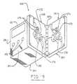
- FIG. 9is a partially diagrammatic perspective view of the excitation and sensing unit of the differential conductivity recirculation monitor of the present invention.
- FIG. 10is a diagrammatic representation of the passage of an ideal bolus of saline and an actual bolus of saline through a conductivity cell of the present invention.
- FIG. 11is an illustration of the output signals from the conductivity cell of FIG. 10 .
- FIG. 1illustrates a dialysis system 20 incorporating a differential conductivity recirculation monitor 22 for determining and displaying recirculation efficiency in accordance with the present invention.
- the dialysis system 20which is one example of a medical system with which the present invention may be advantageously used, comprises a dialysis apparatus 24 connected to a fistula 26 surgically formed in a dialysis patient (not shown). Untreated blood is drawn from the fistula 26 through a dialyzer inlet needle 28 and a dialyzer inlet line 30 . Treated blood is returned to the fistula through a dialyzer outlet line 32 and a dialyzer outlet needle 34 .
- the recirculation monitor 22is located in the dialyzer inlet and outlet lines 30 and 32 at a point intermediate between the fistula 26 and the dialysis apparatus 24 .
- the dialysis apparatus 24comprises a blood pump 36 typically a peristaltic pump, a dialyzer 38 having a blood compartment 40 and a dialysate compartment 42 separated by a semi-permeable membrane 44 , a bubble trap 46 and a dialysate generator 48 .
- Bloodis drawn from the fistula 26 by the action of the blood pump 36 and passed through the blood compartment 40 of the dialyzer 38 .
- the membrane 44allows transfer of impurities in the blood, such as urea and creatinine, from the blood compartment 40 to the dialysate compartment 42 of the dialyzer 38 .
- the dialysate compartment 42is connected to dialysate generator 48 which generates the dialysate, a liquid isotonic to blood, and circulates it through the dialysate compartment 42 .
- the recirculation detector 22comprises a needle access site 50 in the dialyzer outlet line 32 .
- a first or outlet conductivity cell 52is located in the dialyzer outlet line 32 downstream of the needle access site 50 .
- a second or inlet conductivity cell 54is located in the dialyzer inlet line 30 .
- the first conductivity cell 52comprises an upstream connection 56 , a downstream connection 58 and first and second tubing branches 60 and 62 , respectively, each of which interconnect the upstream connection 56 with the downstream connection 58 .
- Treated blood from the dialyzerflows in the dialyzer outlet line 32 through the needle access site 50 to the upstream connection 56 .
- the inlet conductivity cell 54comprises an upstream connection 64 , a downstream connection 66 and third and fourth tubing branches 68 and 70 , respectively, which each connect the upstream connection 64 to the downstream connection 66 .
- Each one of the tubing branches 60 , 62 , 68 and 70has the same cross sectional area and length as each other one of the tubing branches.
- the blood, or other biological or medical fluid, flowing in each conductivity cell 52 and 54comprises an electrical circuit.
- the electrical circuitis a path for circulation of an electrical current from the upstream connection, through one of the tubing branches, to the downstream connection and from the downstream connection through the other one of the tubing branches to the upstream connection.
- the outlet conductivity cell 52 and the inlet conductivity cell 54are positioned adjacent to each other in an angular relationship resembling a pretzel so that the first tubing branch 60 of the outlet conductivity cell 52 is positioned parallel to the third tubing branch 68 of the inlet conductivity cell at an excitation location.
- the conductivity cellsare further positioned so that the second tubing branch 62 of the outlet conductivity cell 52 crosses the fourth tubing branch 70 of the inlet conductivity cell 54 at an angle, approximately sixty degrees in the preferred embodiment, at a sensing location.
- An excitation coil 72encircles the first tubing branch 60 of the outlet conductivity cell 52 and the third tubing branch 68 of the inlet conductivity cell 54 at the excitation location.
- a sensing coil 74encircles the second tubing branch 62 of the outlet conductivity cell 52 and the fourth tubing branch 70 of the inlet conductivity cell 54 at the sensing location.
- the excitation coil 72is inductively coupled to the outlet conductivity cell 52 and the inlet conductivity cell 54 .
- a source of excitation energy 76causes an alternating excitation current, illustrated by direction arrow 78 , to flow in the excitation coil 72 a changing magnetic field is generated which causes an electrical current, illustrated by the direction arrow 80 , to flow in the blood in the outlet conductivity cell 52 and causes another electrical current, illustrated by direction arrow 82 , to flow in the same electrical direction in the blood in the inlet conductivity cell 54 .
- the conductivity cells 52 and 54are formed to create electrical paths of equal cross sectional area and equal path length the electrical conductance of the paths, as illustrated by the schematic resistors 84 and 86 , and thus the magnitude of the induced currents 80 and 82 , will be related to the conductivity of the blood in the respective conductivity cells 52 and 54 .
- the induced currents 80 and 82 flowing in the outlet and inlet conductivity cells 52 and 54generate a changing magnetic field at the sensing location that induces a sensed current, illustrated by direction arrow 88 , in the sensing coil 74 .
- the induced currents 80 and 82are in opposite electrical directions so that the magnetic field at the sensing location has a magnitude proportional to the difference between the induced currents.
- the sensed current 88is proportional to the magnetic field at the sensing location where the sensing coil 74 encircles the second and fourth tubing branches 62 and 70 , respectively.
- the sensed current 88 induced in the sensing transformer 74is therefore proportional to a difference between the induced currents 80 and 82 in the outlet and inlet conductivity cells 52 and 54 , respectively.
- the induced currents 80 and 82 in the outlet and inlet conductivity cells 52 and 54 , respectively,are related to the conductivity of the fluids in those chambers. Therefore, the magnitude of the sensed current 88 induced in the sensing coil 74 will be related to the difference between the conductivities of the fluids in the outlet and inlet conductivity cells 52 and 54 .
- the sensed current 88is delivered to, and interpreted by a sensing logic and display circuit 90 , which displays the recirculation efficiency.
- the dialysis system operatorinjects a bolus of a marker fluid into the treated blood in the dialyzer outlet line 32 at the needle access site 50 using a typical hypodermic needle 92 .
- the marker fluidmay have an electrical conductivity that is higher or lower than the fluid flowing in the outlet line 32 .
- a high conductivity marker fluidis used to avoid damaging blood cells.
- the bolusis 1 milliliter of 24 percent hypertonic saline solution.
- the conductivity of the treated blood being returned to the patient through the dialyzer outlet line 32 and the outlet conductivity cell 52 of the recirculation monitor 22is altered. This altered conductivity blood enters the fistula through the outlet needle 34 .
- the flow balance in the fistula 26is such that no flow is recirculating the altered conductivity blood will exit the fistula, as illustrated by the flow circulation arrow 94 , without altering the conductivity of the blood within the fistula. If, however, the flow balance within the fistula 26 is such that blood is recirculating, as illustrated by flow circulation arrow 96 , a portion of the blood withdrawn from the fistula 26 by the pump 36 will be the altered conductivity blood.
- the recirculation monitor 22measures the conductivity of the blood flowing in the outlet line 32 and the conductivity of the blood flowing in the inlet line 30 and quantitatively determines the difference between those conductivities continuously throughout the recirculation test.
- the sensing logic and display circuit 90interprets the quantitative conductivity differences measured by the recirculation monitor 22 to determine recirculation efficiency.
- the outlet conductivity cell 52 and the inlet conductivity cell 54may be thought of as signal generators generating the induced currents 80 and 82 in the outlet and inlet conductivity cells.
- the induced current 82 of the inlet conductivity cell 54is inverted 98 and added 100 to the induced current 80 in the outlet conductivity cell 52 , by virtue of the physical relationships between the conductivity cells, excitation coil 72 and sensing coil 74 , to produce the sensed current 88 .
- the sensing logic and display circuit 90performs a zeroing operation 102 , a dialyzer outlet flow determining operation 104 , and unrecirculated flow determining operation 106 , and a dividing operation 108 , and includes a visual display device 110 , preferably a liquid crystal display.
- a digital computernot shown.
- FIG. 5is a graph illustrating differential conductivity (reference 112 ) as a function of time (reference 114 ) during a typical recirculation test.
- FIG. 6is a graph illustrating the integral of differential conductivity (reference 116 ) as a function of time 114 during the typical recirculation test.
- reference 118Prior to the beginning of the recirculation test there may be some normal difference (reference 118 ) between the conductivity of the treated blood in the dialyzer outlet line 32 (FIG. 2) and the untreated blood in the dialyzer inlet line 30 (FIG. 2 ).
- This normal conductivity difference 118is subtracted from the sensed current 88 by the zeroing operation 102 of the sensing logic and display circuit 90 to remove the effect of the normal difference in conductivity 118 from determination of recirculation efficiency.
- the recirculation testbegins (reference time T 1 ) when the bolus of high conductivity fluid is injected into the dialyzer outlet line 32 (FIG. 2) at the needle access site 50 (FIG. 2 ). The conductivity of the treated blood in the dialyzer outlet line 32 (FIG. 2) is increased. As the bolus passes through the outlet conductivity cell 52 (FIG. 2) the differential conductivity 112 increases (reference 120 ) and then decreases (reference 122 ) until the normal conductivity difference 118 is reached (reference time T 2 ).
- the outlet flow determining operation 104calculates the integral of conductivity from the start of the test (reference time T 1 ) until the differential conductivity returns to the normal value 118 (reference time T 2 ).
- the integral 116 of the conductivityincreases (reference 124 ) until a first steady state value (reference 126 ) of the integral 116 is reached when the differential conductivity 112 returns to the normal value 118 (reference time T 2 ).
- the first steady state value 126is stored by the outlet flow determining operation 104 and is representative of the flow of treated blood in the dialyzer outlet line 32 (FIG. 2 ).
- the integral of differential conductivity from the beginning of the recirculation test (reference time T 1 ) until the normal value of conductivity difference 118 is reached again (reference time T 4 )is calculated by the unrecirculated flow determining operation 106 of the sensing logic and display circuit 90 .
- the integral of differential conductivity 116decreases (reference) to a second steady state value 134 (reference time T 4 .
- the second steady state value 134 of the integral of differential conductivityis stored by the unrecirculated flow determining operation 106 of the sensing logic and display circuit 90 and is representative of the portion of the bolus of high conductivity liquid that was not recirculated.
- the second steady state value 134is thus representative of the unrecirculated portion of the treated blood flow.
- the dividing operationdivides the second steady state value 134 by the first steady state value 126 to calculate a recirculation efficiency 136 .
- the recirculation efficiency 136is provided to the operator as a visual output by the display device 110 .
- sensing logic and display circuit 90may be implemented using analog or digital circuit devices and that other calculation algorithms may be used to calculate recirculation efficiency 138 . Further, the recirculation efficiency 138 may be calculated in real time or, alternatively, the necessary data stored and the calculations performed on the stored data.
- FIG. 7illustrates a portion of a typical disposable tubing set 140 incorporating conductivity cells 52 and 54 in accordance with the present invention.
- a typical disposable tubing set 140incorporating conductivity cells 52 and 54 in accordance with the present invention.
- Disposable tubing setsmay be formed from a plurality of plastic tubes, connectors, needles and medical devices using techniques that are well known in the art.
- the discussion of the tubing set 140will therefore be limited to a discussion of the differential conductivity recirculation monitor 22 (FIG. 1) portion of the tubing set.
- the dialyzer outlet line 32is a plastic tube which extends through the needle access site 50 , into the outlet conductivity cell 52 .
- the outlet conductivity cell 52comprises a plastic conduit loop and includes the upstream connection 56 , elongated divided first and second tubing branches 60 and 62 , and the downstream connector 58 .
- the downstream connector 58has mounted in it an extension of the dialyzer outlet line 32 , which is mounted through a connector 142 to the outlet needle 34 .
- the dialyzer inlet needle 28is connected through a connector 144 , to the dialyzer inlet line 30 .
- the dialyzer inlet line 30is connected to the inlet conductivity cell 54 , which includes the upstream connection 64 , elongated divided third and fourth tubing branches 68 and 70 respectively, and downstream connector 66 .
- the dialyzer inlet line 30extends from the downstream connector 66 to the dialyzer apparatus 24 (FIG. 1 ).
- portion of the dialyzer outlet line 32 between the dialyzer outlet needle 34 and the downstream connector 58 of the outlet conductivity cell 52 and the portion of the dialyzer inlet line 30 between the dialyzer inlet needle 28 and the upstream connector 64 of the inlet conductivity cell 54must be sufficiently long so that the bolus of marker fluid passes completely through the outlet conductivity cell before any altered conductivity fluid from the fistula 26 enters the inlet conductivity cell.
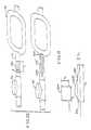
- the conductivity cells 52 and 54have the overall shape of links in an ordinary chain, straight side portions 146 being joined at their ends by semicircular portions 148 .
- the wall of each conductivity cell 42 and 54defines a D, the insides of the Ds providing conduit portions 150 and 152 .
- a flat portion 154 of the D of the outlet conductivity cell 52is abutted and adhered to a flat portion 156 of the D of the inlet conductivity cell 54 along one pair of semicircular portions 148 of the conductivity cells.
- the other pair of circular portions 148are separated so that axes of the conductivity cells 52 and 54 define therebetween an angle of approximately sixty degrees.
- the flat portions 154 and 156 of the conductivity cells 52 and 54are further joined along two of the straight portions 146 at a location along the second and fourth tubing branches 62 and 70 , respectively at the sensing location.
- An orientation tab 159is formed on the inlet conductivity cell 54 .
- the tubing set acceptor 160comprises a portion of an excitation and sensing unit 162 which also includes a logic circuit module 164 .
- the tubing set acceptor 160comprises a portion of a first, or rear, acceptor plate 166 and a second, or front, acceptor plate 168 joined by a hinge 169 for motion between open and closed positions and provided with a latch or spring (not shown) to hold the acceptor plates in the closed position.
- the first acceptor 166 plateis relieved to accept into appropriately-shaped indentations 170 thereof the outlet conductivity cell 52 (FIG. 2) and portions the tubing set 140 (FIG. 7 ).
- the second acceptor plate 168is relieved to accept into appropriately-shaped indentations 172 thereof the inlet conductivity cell 54 and portions of the tubing set 140 (FIG. 7 ).
- An orientation tab recess 173is defined by at least one of the appropriately shaped indentations 170 and 172 .
- the orientation tab recess 173cooperates with the orientation tab 159 (FIG. 7) of the tubing set 140 (FIG. 7) to assure that the tubing set is correctly oriented when installed in the tubing set acceptor 160 .
- the tubing set acceptor 160is sufficiently large to support the conductivity cells 52 and 54 and enough of the dialyzer outlet line 32 and dialyzer inlet line 30 so that fluid flow patterns through the conductivity cells are substantially repeatable, being relatively unaffected by bends, curves, tubing movement, and other disturbances or variations in the positions of the outlet and inlet lines with respect to the conductivity cells during measurement.
- the excitation coil 72 and sensing coil 74are mounted to the tubing set acceptor 160 .
- the excitation coil 72 and sensing coil, 74are positioned at right angles to each other to minimize magnetic interference between the coils.
- the excitation coil 72comprises a first, or rear, and a second, or front, half core 174 and 176 , respectively.
- the sensing coilcomprises a third, or rear, and a fourth, or front, half-core 178 and 180 respectively.
- the first and third half-cores 174 and 178respectively are mounted to the first acceptor plate 166 and the second and third half cores 176 and 180 respectively are mounted to the second acceptor plate 186 .
- each half corehas a U-shaped configuration, with short legs 162 having ends 184 and connecting legs 186 .
- the tubing set acceptor 160holds a portion of the tubing set 140 which includes the conductivity cells 52 and 54 in a fixed relationship with the excitation coil 72 and sensing coil 74 .
- the first and second half cores 174 and 176are oriented so that their ends 184 abut when the first and second acceptor plates 166 and 166 are brought to the closed position.
- the excitation coil 72 thus formedis in the shape of a rectangle defining a rectangular window.
- the third and fourth half cores 178 and 180are similarly oriented so that their ends abut when the first and second acceptor plates 166 and 168 are brought to the closed position.
- the sensing coil 74 thus formedis also in the shape of a rectangular ring defining a rectangular window (not shown).
- Biasing springs 188may be provided to hold corresponding half-cores in firm contact when the acceptor plates 166 and 168 are closed.
- the legs 182 and 186 of the coil 72 and 74are square in cross-section. At least one connecting leg 186 of each coil 72 and 74 is transformer wire wrapped 190 .
- the logic circuit module 164 of the excitation and sensing unit 162may be mounted to one of the acceptor plates 168 or may be separate from the tubing set acceptor 160 with wiring interconnections (not shown) to the tubing set acceptor 160 . Further, either or both of the logic circuit module 164 or the tubing set acceptor 160 may be incorporated into the dialysis apparatus 24 .
- the logic circuit modulehouses the sensing logic and display circuit 90 , with the display device 110 and one or more manual input switches 192 to enable the operator to perform such functions as turning the recirculation monitor on and off, testing the operation of the monitor and initiating recirculation test, and may also include switches and displays associated with other hemodynamic monitoring functions.
- the display device 110 and manual input switches 192are shown in FIG. 9 as being on a side 194 of the logic circuit module 164 adjacent to the second acceptor plate 168 , in the preferred embodiment the display device and manual input switches may be on a side 196 opposite the second acceptor plate 168 , or any other side of the logic circuit module.
- circuitry for conductivity measurement and calibrationmay suitably be as set forth in the Ogawa patent incorporated by reference above.
- the apparatus and methods described abovemay optionally be adapted to measure and detect other hemodynamic parameters such as the presence of entrained air in the treated blood returned to the patient from the dialysis apparatus 24 through the dialyzer outlet line 32 .
- hemodynamic parameterssuch as the presence of entrained air in the treated blood returned to the patient from the dialysis apparatus 24 through the dialyzer outlet line 32 .
- Entrained air in the blood in the form of a large bubblewill cause an electrical discontinuity in the outlet conductivity cell 52 as it passes through either of the tubing branches 60 , 62 of the outlet conductivity cell 52 .
- Thiswill cause the magnitude of induced current 80 flowing in the outlet conductivity cell 52 to be greatly reduced or turned off completely, depending on the size of the bubble.
- a plurality of small bubbleswill effectively reduce the conducting volume of the blood in the tubing branches 60 , 62 of the conductivity cell, decreasing the conductance, and therefore the induced current 80 , in the outlet
- Corrective actionmay include turning off the dialysis apparatus 24 , closing a venous clasp (not shown) and/or activating indicator or alarm devices to alert a human operator of the presence of the air bubble of bubbles.
- a difference in the conductivity of the blood in the outlet conductivity cell 52 of the outlet line 32 and the blood in the inlet conductivity cell of the inlet line 30is substantially constantly monitored.
- this decreaseis sensed by logic in the sensing logic and display circuit 90 of the logic circuit module 164 of the excitation and sensing unit 162 . If the conductivity of the blood in the outlet conductivity cell 52 is sufficiently lower than the conductivity of the blood in the inlet conductivity cell 54 , this conductivity difference is interpreted as the presence of entrained air in the outlet line 32 .
- Blood volumetric flow ratemay be measured and displayed as an incident to the measurement of a degree of recirculation, as described above, or may be measured in a separate blood volumetric flow monitoring procedure.
- Ct 1is the area under the sensed square pulse 204 .
- the bolus 202 ′ of known volume vol and known mass of conductivity altering ions Mwill not take the form of a perfect cylinder, but will exhibit gradual Leading edge curve 206 and trailing edge curve 209 , and will further diffuse into the fluid in the outlet line 32 .
- the differential conductivity pulse 204 ′ caused by the passage of the bolus 202 ′ through the outlet conductivity cell 52will deviate substantially from a square pulse and will have gradually increasing and decreasing leading and trailing edges 210 , 212 corresponding to the leading and trailing edges 206 , 208 of the bolus.
- the time t 2 that the bolus 202 ′ takes to pass through the outlet conductivity cellwill be longer than the time t 1 for an ideal bolus 202 .
- C bis representative of a difference in background concentration, and hence conductivity, between the fluid in the outlet conductivity cell. 52 and the fluid in the inlet conductivity cell. If, under steady state conditions, the conductivity of fluid in the outlet cell. 52 is the same as the conductivity in the inlet cell, then the background concentration C b is zero.
- the preferred embodiment of the present inventionmay optionally be provided with selectably engageable logic to analyze a differential conductivity pulse from the bolus 202 ′ of saline passing through the outlet conductivity cell 52 and generate a value indicative of the flow rate through the conductivity cell. This value may be selectively displayable on the same display device 110 as is used to display a degree of recirculation.
- the bolus of saline 202 ′may optionally be the same bolus used to determine a degree of recirculation, in which case the flow rate will be determined substantially simultaneously with the degree of recirculation and displayed simultaneously of sequentially therewith.
- the apparatus and methods described abovemay optionally be further adapted to incorporate the capability of measuring or detecting more than one hemodynamic parameter into a single differential conductivity measuring apparatus.
- the preferred embodiments of the present inventionbeen described by reference to determination of recirculation efficiency in a surgically created blood access site during, or in conjunction with, a hemodialysis procedure. It should be understood that the present invention is not so limited. The present invention may be used in a variety of medical and non-medical circumstances where it is desirable to determine recirculation efficiency. Further, it should be understood that the present invention may be used in a variety of medical and non-medical circumstances where it is desirable to compare the electrical conductivities of two fluids. Presently preferred embodiments of the present invention and many of its aspects, features and advantages have been described with a degree of particularity. It should be understood that this description has been made by way of preferred example, and that the invention is defined by the scope of the following claims.
Landscapes
- Health & Medical Sciences (AREA)
- Heart & Thoracic Surgery (AREA)
- Vascular Medicine (AREA)
- Animal Behavior & Ethology (AREA)
- Hematology (AREA)
- Veterinary Medicine (AREA)
- Public Health (AREA)
- Engineering & Computer Science (AREA)
- Anesthesiology (AREA)
- Biomedical Technology (AREA)
- General Health & Medical Sciences (AREA)
- Life Sciences & Earth Sciences (AREA)
- Cardiology (AREA)
- Physics & Mathematics (AREA)
- Fluid Mechanics (AREA)
- General Physics & Mathematics (AREA)
- Urology & Nephrology (AREA)
- Emergency Medicine (AREA)
- External Artificial Organs (AREA)
Abstract
Description


Claims (20)
Priority Applications (3)
| Application Number | Priority Date | Filing Date | Title |
|---|---|---|---|
| US09/563,107US6452371B1 (en) | 1992-09-30 | 2000-05-02 | Differential conductivity hemodynamic monitor |
| US10/238,164US6614212B2 (en) | 1992-09-30 | 2002-09-10 | Differential conductivity hemodynamic monitor |
| US10/630,004US6912917B2 (en) | 1992-09-30 | 2003-07-29 | Differential fluid parameter determination |
Applications Claiming Priority (6)
| Application Number | Priority Date | Filing Date | Title |
|---|---|---|---|
| US95458492A | 1992-09-30 | 1992-09-30 | |
| US08/332,647US5510716A (en) | 1992-09-30 | 1994-11-01 | Differential conductivity recirculation monitor |
| US08/486,982US5644240A (en) | 1992-09-30 | 1995-06-07 | Differential conductivity hemodynamic monitor |
| US08/876,445US5900726A (en) | 1992-09-30 | 1997-06-16 | Differential conductivity hemodynamic monitor |
| US09/220,139US6075367A (en) | 1992-09-30 | 1998-12-23 | Differential conductivity hemodynamic monitor |
| US09/563,107US6452371B1 (en) | 1992-09-30 | 2000-05-02 | Differential conductivity hemodynamic monitor |
Related Parent Applications (1)
| Application Number | Title | Priority Date | Filing Date |
|---|---|---|---|
| US09/220,139ContinuationUS6075367A (en) | 1992-09-30 | 1998-12-23 | Differential conductivity hemodynamic monitor |
Related Child Applications (1)
| Application Number | Title | Priority Date | Filing Date |
|---|---|---|---|
| US10/238,164ContinuationUS6614212B2 (en) | 1992-09-30 | 2002-09-10 | Differential conductivity hemodynamic monitor |
Publications (1)
| Publication Number | Publication Date |
|---|---|
| US6452371B1true US6452371B1 (en) | 2002-09-17 |
Family
ID=46202693
Family Applications (6)
| Application Number | Title | Priority Date | Filing Date |
|---|---|---|---|
| US08/486,982Expired - LifetimeUS5644240A (en) | 1992-09-30 | 1995-06-07 | Differential conductivity hemodynamic monitor |
| US08/876,445Expired - Fee RelatedUS5900726A (en) | 1992-09-30 | 1997-06-16 | Differential conductivity hemodynamic monitor |
| US09/220,139Expired - Fee RelatedUS6075367A (en) | 1992-09-30 | 1998-12-23 | Differential conductivity hemodynamic monitor |
| US09/563,107Expired - Fee RelatedUS6452371B1 (en) | 1992-09-30 | 2000-05-02 | Differential conductivity hemodynamic monitor |
| US10/238,164Expired - Fee RelatedUS6614212B2 (en) | 1992-09-30 | 2002-09-10 | Differential conductivity hemodynamic monitor |
| US10/630,004Expired - Fee RelatedUS6912917B2 (en) | 1992-09-30 | 2003-07-29 | Differential fluid parameter determination |
Family Applications Before (3)
| Application Number | Title | Priority Date | Filing Date |
|---|---|---|---|
| US08/486,982Expired - LifetimeUS5644240A (en) | 1992-09-30 | 1995-06-07 | Differential conductivity hemodynamic monitor |
| US08/876,445Expired - Fee RelatedUS5900726A (en) | 1992-09-30 | 1997-06-16 | Differential conductivity hemodynamic monitor |
| US09/220,139Expired - Fee RelatedUS6075367A (en) | 1992-09-30 | 1998-12-23 | Differential conductivity hemodynamic monitor |
Family Applications After (2)
| Application Number | Title | Priority Date | Filing Date |
|---|---|---|---|
| US10/238,164Expired - Fee RelatedUS6614212B2 (en) | 1992-09-30 | 2002-09-10 | Differential conductivity hemodynamic monitor |
| US10/630,004Expired - Fee RelatedUS6912917B2 (en) | 1992-09-30 | 2003-07-29 | Differential fluid parameter determination |
Country Status (1)
| Country | Link |
|---|---|
| US (6) | US5644240A (en) |
Cited By (13)
| Publication number | Priority date | Publication date | Assignee | Title |
|---|---|---|---|---|
| US6725072B2 (en) | 1990-10-06 | 2004-04-20 | Hema Metrics, Inc. | Sensor for transcutaneous measurement of vascular access blood flow |
| US6746407B2 (en)* | 2000-12-29 | 2004-06-08 | Hema Metrics, Inc. | Method of measuring transcutaneous access blood flow |
| US6804543B2 (en) | 1998-02-05 | 2004-10-12 | Hema Metrics, Inc. | Sensor for transcutaneous measurement of vascular access blood flow |
| US20060243050A1 (en)* | 2005-05-02 | 2006-11-02 | Quackenbush John K | Non-metallic flow-through electrodeless conductivity sensor and leak detector |
| US20070131595A1 (en)* | 2005-12-13 | 2007-06-14 | Gambro Lundia Ab | Method for conductivity calculation in a treatment fluid upstream and downstream a filtration unit in apparatuses for the blood treatment |
| US7279903B2 (en) | 2005-05-02 | 2007-10-09 | Invensys Systems, Inc. | Non-metallic flow-through electrodeless conductivity sensor with leak and temperature detection |
| US20090308571A1 (en)* | 2008-05-09 | 2009-12-17 | Thermal Centric Corporation | Heat transfer assembly and methods therefor |
| DE102010003642A1 (en)* | 2010-03-15 | 2011-09-15 | Fresenius Medical Care Deutschland Gmbh | Cassette with a sensor for determining the difference between a first and a second liquid flow |
| US8114043B2 (en) | 2008-07-25 | 2012-02-14 | Baxter International Inc. | Electromagnetic induction access disconnect sensor |
| US8529490B2 (en) | 2002-04-10 | 2013-09-10 | Baxter International Inc. | Systems and methods for dialysis access disconnection |
| US8708946B2 (en) | 2002-04-10 | 2014-04-29 | Baxter International Inc. | Access disconnection systems using conductive contacts |
| US8920356B2 (en) | 2002-04-10 | 2014-12-30 | Baxter International Inc. | Conductive polymer materials and applications thereof including monitoring and providing effective therapy |
| US10155082B2 (en) | 2002-04-10 | 2018-12-18 | Baxter International Inc. | Enhanced signal detection for access disconnection systems |
Families Citing this family (76)
| Publication number | Priority date | Publication date | Assignee | Title |
|---|---|---|---|---|
| US5644240A (en)* | 1992-09-30 | 1997-07-01 | Cobe Laboratories, Inc. | Differential conductivity hemodynamic monitor |
| US6153109A (en)* | 1994-09-16 | 2000-11-28 | Transonic Systmes, Inc. | Method and apparatus to measure blood flow rate in hemodialysis shunts |
| US6514419B2 (en)* | 1994-09-16 | 2003-02-04 | Transonic Systems, Inc. | Method to measure blood flow and recirculation in hemodialysis shunts |
| US8290721B2 (en) | 1996-03-28 | 2012-10-16 | Rosemount Inc. | Flow measurement diagnostics |
| US7623932B2 (en) | 1996-03-28 | 2009-11-24 | Fisher-Rosemount Systems, Inc. | Rule set for root cause diagnostics |
| US7630861B2 (en) | 1996-03-28 | 2009-12-08 | Rosemount Inc. | Dedicated process diagnostic device |
| US7949495B2 (en) | 1996-03-28 | 2011-05-24 | Rosemount, Inc. | Process variable transmitter with diagnostics |
| IT1288767B1 (en)* | 1996-10-18 | 1998-09-24 | Hospal Dasco Spa | METHOD OF DETERMINING THE VALUE OF THE RECIRCULATION OF A SUSPENSION SUBJECT TO TREATMENT. |
| US5928180A (en)* | 1997-03-25 | 1999-07-27 | Krivitski; Nikolai M. | Method and apparatus for real time monitoring of blood volume in a filter |
| SE513034C2 (en) | 1997-06-02 | 2000-06-19 | Gambro Lundia Ab | Calculation of dialysis efficiency, especially by monitoring urea concentration |
| FR2771931B1 (en)* | 1997-12-09 | 2000-01-07 | Hospal Ind | METHOD FOR DETERMINING A SIGNIFICANT PARAMETER OF THE PROGRESS OF AN EXTRACORPOREAL BLOOD TREATMENT |
| SE9702074D0 (en) | 1997-06-02 | 1997-06-02 | Gambro Ab | Method and device for calculating dialysis efficiency |
| DE19739099C1 (en)* | 1997-09-06 | 1999-01-28 | Fresenius Medical Care De Gmbh | Monitoring of a blood container inlet during external blood treatment |
| DE69829358T2 (en) | 1997-11-06 | 2006-04-06 | Koninklijke Philips Electronics N.V. | EXTERNAL DEFIBRILLATOR WITH CPR INDICATIONS AND WITH ACLS INDICATIONS |
| US6648845B1 (en) | 1998-01-07 | 2003-11-18 | Fresenius Medical Care North America | Method and apparatus for determining hemodialysis parameters |
| US6177049B1 (en) | 1998-06-10 | 2001-01-23 | Dsu Medical Corporation | Reversing flow blood processing system |
| US6167765B1 (en) | 1998-09-25 | 2001-01-02 | The Regents Of The University Of Michigan | System and method for determining the flow rate of blood in a vessel using doppler frequency signals |
| US6575927B1 (en) | 1998-09-25 | 2003-06-10 | The Regents Of The University Of Michigan | System and method for determining blood flow rate in a vessel |
| US6726647B1 (en)* | 1998-10-23 | 2004-04-27 | Gambro Ab | Method and device for measuring access flow |
| US6611770B1 (en)* | 1998-12-10 | 2003-08-26 | Rosemount Inc. | Liquid conduction indication in a magnetic flowmeter |
| US6615149B1 (en) | 1998-12-10 | 2003-09-02 | Rosemount Inc. | Spectral diagnostics in a magnetic flow meter |
| US6611775B1 (en) | 1998-12-10 | 2003-08-26 | Rosemount Inc. | Electrode leakage diagnostics in a magnetic flow meter |
| ATE354386T1 (en)* | 1998-12-24 | 2007-03-15 | Fresenius Medical Care De Gmbh | DEVICE FOR DETERMINING THE DISTRIBUTION VOLUME OF A BLOOD CONTENT DURING BLOOD TREATMENT |
| US6319465B1 (en) | 1999-06-03 | 2001-11-20 | Dsu Medical Corporation | Reversing flow blood processing system having reduced clotting potential |
| US6868739B1 (en)* | 1999-10-19 | 2005-03-22 | Transonic Systems, Inc. | Method and apparatus to measure blood flow by an introduced volume change |
| IT1308687B1 (en)* | 1999-12-28 | 2002-01-09 | Gambro Dasco Spa | METHOD AND DEVICE FOR THE DETECTION OF ACCESS TO THE CARDIVASCULAR SYSTEM IN AN EXTRA-BODY BLOOD TREATMENT IN A |
| GB0028647D0 (en)* | 2000-11-24 | 2001-01-10 | Nextgen Sciences Ltd | Apparatus for chemical assays |
| ITTO20010583A1 (en)* | 2001-06-15 | 2002-12-15 | Gambro Dasco Spa | BLOOD CIRCULATION CIRCUIT FOR A DIALYSIS MACHINE AND RELATED DIALYSIS MACHINE. |
| US20030083901A1 (en)* | 2001-06-22 | 2003-05-01 | Bosch Juan P. | Process for providing dialysis and other treatments |
| FR2836831B1 (en)* | 2002-03-07 | 2004-06-25 | Centre Nat Rech Scient | COMBINATION OF CHEMOTHERAPY AND ANTISENSE OF DNA DEMETHYLASE |
| US7138088B2 (en)* | 2002-04-10 | 2006-11-21 | Baxter International Inc. | Access disconnection system and methods |
| USRE49221E1 (en) | 2002-06-14 | 2022-09-27 | Parker Intangibles, Llc | Single-use manifolds for automated, aseptic handling of solutions in bioprocessing applications |
| EP1930035A1 (en)* | 2003-01-28 | 2008-06-11 | Gambro Lundia AB | Apparatus for monitoring a vascular access |
| US7627441B2 (en) | 2003-09-30 | 2009-12-01 | Rosemount Inc. | Process device with vibration based diagnostics |
| WO2005049113A1 (en)* | 2003-11-20 | 2005-06-02 | Gambro Lundia Ab | Method, apparatus and software program for measurement of a parameter relating to a heart-lung system of a mammal. |
| WO2005061043A1 (en)* | 2003-12-11 | 2005-07-07 | Gambro Lundia Ab | Switching device and apparatus for controlling flow of a fluid |
| US7523667B2 (en) | 2003-12-23 | 2009-04-28 | Rosemount Inc. | Diagnostics of impulse piping in an industrial process |
| US6920799B1 (en) | 2004-04-15 | 2005-07-26 | Rosemount Inc. | Magnetic flow meter with reference electrode |
| US7758530B2 (en)* | 2004-11-10 | 2010-07-20 | Bard Access Systems, Inc. | Method for measuring recirculation in catheters |
| WO2006123197A1 (en)* | 2005-05-18 | 2006-11-23 | Gambro Lundia Ab | An apparatus for controlling blood flow in an extracorporeal circuit. |
| US8112565B2 (en) | 2005-06-08 | 2012-02-07 | Fisher-Rosemount Systems, Inc. | Multi-protocol field device interface with automatic bus detection |
| WO2007009496A1 (en)* | 2005-07-22 | 2007-01-25 | Mahiout Arezki Ph D | Differential hemodialysis or hemodiafiltration |
| US20070068225A1 (en) | 2005-09-29 | 2007-03-29 | Brown Gregory C | Leak detector for process valve |
| JP4925159B2 (en)* | 2005-10-12 | 2012-04-25 | 日機装株式会社 | Blood purification equipment |
| US7857506B2 (en)* | 2005-12-05 | 2010-12-28 | Sencal Llc | Disposable, pre-calibrated, pre-validated sensors for use in bio-processing applications |
| ES2701984T3 (en)* | 2006-08-04 | 2019-02-26 | Medica S P A | Conductivity probe and dialysis machine including the probe |
| US7953501B2 (en) | 2006-09-25 | 2011-05-31 | Fisher-Rosemount Systems, Inc. | Industrial process control loop monitor |
| US8788070B2 (en) | 2006-09-26 | 2014-07-22 | Rosemount Inc. | Automatic field device service adviser |
| US7750642B2 (en) | 2006-09-29 | 2010-07-06 | Rosemount Inc. | Magnetic flowmeter with verification |
| US7321846B1 (en) | 2006-10-05 | 2008-01-22 | Rosemount Inc. | Two-wire process control loop diagnostics |
| US8398852B2 (en)* | 2006-10-12 | 2013-03-19 | Bruce D. Burrows | Drainless reverse osmosis water purification system |
| US9371245B2 (en) | 2006-10-12 | 2016-06-21 | Bruce D. Burrows | Drainless reverse osmosis water purification system |
| US7837866B2 (en)* | 2006-10-12 | 2010-11-23 | Burrows Bruce D | Drainless reverse osmosis water purification system |
| US20080108930A1 (en)* | 2006-11-03 | 2008-05-08 | The Regents Of The University Of Michigan | Methods and Systems for Determining Volume Flow in a Blood or Fluid Conduit, Motion, and Mechanical Properties of Structures Within the Body |
| US7955328B2 (en) | 2006-11-10 | 2011-06-07 | Ethicon Endo-Surgery, Inc. | Tissue dissector and/or coagulator with a slit in an insulating tip to control the direction of energy |
| US20090007642A1 (en)* | 2007-07-05 | 2009-01-08 | Baxter International Inc. | Dialysis fluid measurement method and apparatus using conductive contacts |
| US8287724B2 (en)* | 2007-07-05 | 2012-10-16 | Baxter International Inc. | Dialysis fluid measurement systems using conductive contacts |
| US8898036B2 (en) | 2007-08-06 | 2014-11-25 | Rosemount Inc. | Process variable transmitter with acceleration sensor |
| US7590511B2 (en) | 2007-09-25 | 2009-09-15 | Rosemount Inc. | Field device for digital process control loop diagnostics |
| US7921734B2 (en) | 2009-05-12 | 2011-04-12 | Rosemount Inc. | System to detect poor process ground connections |
| DE102009048920A1 (en)* | 2009-10-10 | 2011-04-14 | Fresenius Medical Care Deutschland Gmbh | Apparatus and method for checking a filter for an extracorporeal blood treatment device |
| US9207670B2 (en) | 2011-03-21 | 2015-12-08 | Rosemount Inc. | Degrading sensor detection implemented within a transmitter |
| WO2012129501A2 (en) | 2011-03-23 | 2012-09-27 | Nxstage Medical, Inc. | Peritoneal dialysis systems, devices, and methods |
| US9861733B2 (en) | 2012-03-23 | 2018-01-09 | Nxstage Medical Inc. | Peritoneal dialysis systems, devices, and methods |
| US9052240B2 (en) | 2012-06-29 | 2015-06-09 | Rosemount Inc. | Industrial process temperature transmitter with sensor stress diagnostics |
| US9602122B2 (en) | 2012-09-28 | 2017-03-21 | Rosemount Inc. | Process variable measurement noise diagnostic |
| DE102013103221A1 (en)* | 2013-03-28 | 2014-10-02 | B. Braun Avitum Ag | Method for detecting recirculation in an arteriovenous shunt during ongoing hemodialysis and dialysis |
| US10183874B2 (en) | 2013-12-18 | 2019-01-22 | Ds Services Of America, Inc. | Water purification system with active vibration |
| JP6575996B2 (en)* | 2015-07-17 | 2019-09-18 | 東レ・メディカル株式会社 | Dialysis machine |
| US10406269B2 (en) | 2015-12-29 | 2019-09-10 | Fresenius Medical Care Holdings, Inc. | Electrical sensor for fluids |
| US10617809B2 (en) | 2015-12-29 | 2020-04-14 | Fresenius Medical Care Holdings, Inc. | Electrical sensor for fluids |
| CN109310338B (en) | 2016-06-29 | 2021-11-19 | 皮科洛医疗公司 | Device and method for vessel navigation, evaluation and/or diagnosis |
| WO2018092069A1 (en)* | 2016-11-16 | 2018-05-24 | IdeaCuria Inc. | System and method for electrical and magnetic monitoring of a material |
| CA2956749A1 (en) | 2017-01-27 | 2018-07-27 | Global Inspections-Ndt, Inc. | Form-fitting eddy current array sensor and method of use thereof |
| EP3641850B1 (en) | 2017-06-24 | 2024-10-09 | NxStage Medical Inc. | Peritoneal dialysis fluid preparation systems |
| JP2021516089A (en) | 2018-02-28 | 2021-07-01 | ネクステージ メディカル インコーポレイテッド | Fluid preparation and treatment equipment, methods, and systems |
Citations (35)
| Publication number | Priority date | Publication date | Assignee | Title |
|---|---|---|---|---|
| US2709785A (en) | 1951-05-03 | 1955-05-31 | Robertshaw Fulton Controls Co | Measurement of conductivity of liquids |
| US3324720A (en) | 1963-07-29 | 1967-06-13 | Friends Of Psychiatric Res Inc | Apparatus and method for determining rate of flow by measurement of electrical property of stream |
| US3396331A (en) | 1965-08-19 | 1968-08-06 | Beckman Instruments Inc | Method of and apparatus for measuring the electrical conductivity of a solution |
| US3404336A (en) | 1965-07-26 | 1968-10-01 | Beckman Instruments Inc | Apparatus for measuring electrical conductivity of a fluid |
| US3450984A (en) | 1965-10-21 | 1969-06-17 | Avco Corp | Method and apparatus for measuring the flow velocity of an electrolytic fluid by electrolysis |
| US3482575A (en) | 1967-02-16 | 1969-12-09 | Single Cell Research Foundatio | Method for the extracorporeal oxygenation of blood |
| US3491592A (en) | 1967-10-23 | 1970-01-27 | Nalco Chemical Co | Measurement of flow rate of aqueous streams |
| US3619423A (en) | 1970-04-20 | 1971-11-09 | Us Health Education & Welfare | Cascade dialysis apparatus and method |
| US3722276A (en) | 1971-12-06 | 1973-03-27 | Tetradyne Corp | Volumetric flow rate measurement of a flowing stream |
| US3867688A (en) | 1973-12-18 | 1975-02-18 | Atomic Energy Commission | Electrodeless conductance measurement device |
| SU521891A1 (en) | 1975-02-27 | 1976-07-25 | Московский Областной Ордена Трудового Красного Знамени Научно-Исследовательский Клинический Институт Им. М.Ф.Владимирского | Method of managing hemodialysis |
| US3980946A (en) | 1974-04-05 | 1976-09-14 | Societe Anonyme Automobiles Citroen | Apparatus for measuring the electrical conductivity of a liquid |
| JPS5236990A (en) | 1975-09-19 | 1977-03-22 | Tdk Corp | Solar cell |
| US4081372A (en) | 1975-12-08 | 1978-03-28 | University Of Utah | Leakage indicator for recirculating peritoneal dialysis system |
| US4136563A (en) | 1977-09-30 | 1979-01-30 | Tetradyne Corporation | Digital volumetric flow rate measurement of a flowing fluid |
| US4138639A (en) | 1977-07-14 | 1979-02-06 | Hutchins Thomas B | Fluid conductivity measurement |
| US4181610A (en) | 1975-07-14 | 1980-01-01 | Takeda Chemical Industries, Ltd. | Blood leak detector suitable for use with artificial kidneys |
| GB2093192A (en) | 1981-02-16 | 1982-08-25 | Ici Plc | Apparatus for measuring conductivity |
| US4361049A (en) | 1980-08-18 | 1982-11-30 | The Hospital For Sick Children | Apparatus for calculating cardiac output |
| SU1013853A1 (en) | 1981-05-27 | 1983-04-23 | Оренбургский Государственный Медицинский Институт | Method of determination of inflammation process in organism |
| EP0097366A2 (en) | 1982-06-21 | 1984-01-04 | Fresenius AG | Dialysis device with controlled composition of dialysis solution |
| US4508622A (en) | 1982-06-21 | 1985-04-02 | Fresenius Ag | Dialysis apparatus with regulated mixing of the dialysis solution |
| JPS60190873A (en) | 1984-03-10 | 1985-09-28 | Japan Organo Co Ltd | Electromagnetic type conductivity meter |
| US4650458A (en) | 1984-06-18 | 1987-03-17 | Gambro Lundia Ab | Apparatus for the measurement of fluid flow |
| US4739492A (en) | 1985-02-21 | 1988-04-19 | Cochran Michael J | Dialysis machine which verifies operating parameters |
| US4740755A (en) | 1986-05-30 | 1988-04-26 | Cobe Laboratories, Inc. | Remote conductivity sensor having transformer coupling in fluid flow path |
| EP0272414A2 (en) | 1986-11-24 | 1988-06-29 | Fresenius AG | Device to determine the intravasal blood volume during hemodialysis |
| US4825168A (en) | 1986-05-30 | 1989-04-25 | Cobe Laboratories, Inc. | Remote conductivity sensor using square wave excitation |
| US4995268A (en) | 1989-09-01 | 1991-02-26 | Ash Medical System, Incorporated | Method and apparatus for determining a rate of flow of blood for an extracorporeal blood therapy instrument |
| US5004459A (en) | 1984-07-09 | 1991-04-02 | Peabody Alan M | Continuous cyclic peritoneal dialysis system and method |
| US5092836A (en) | 1989-03-25 | 1992-03-03 | Fresenius Ag | Hemodialysis apparatus with automatic adjustment of dialysis solution flow |
| US5312550A (en) | 1992-04-27 | 1994-05-17 | Hester Robert L | Method for detecting undesired dialysis recirculation |
| US5453576A (en) | 1994-10-24 | 1995-09-26 | Transonic Systems Inc. | Cardiovascular measurements by sound velocity dilution |
| US5510716A (en) | 1992-09-30 | 1996-04-23 | Cobe Laboratories, Inc. | Differential conductivity recirculation monitor |
| US5685989A (en) | 1994-09-16 | 1997-11-11 | Transonic Systems, Inc. | Method and apparatus to measure blood flow and recirculation in hemodialysis shunts |
Family Cites Families (8)
| Publication number | Priority date | Publication date | Assignee | Title |
|---|---|---|---|---|
| US3015061A (en)* | 1960-02-05 | 1961-12-26 | Foxboro Co | Magnetomotive force device |
| US3996925A (en)* | 1975-05-05 | 1976-12-14 | Ljubomir Djordjevich | System for determining characteristics of blood flow |
| US4407363A (en) | 1981-02-17 | 1983-10-04 | Ava International | Subsurface well apparatus |
| US4697147A (en)* | 1985-11-14 | 1987-09-29 | Metriflow, Inc. | Blood flow imaging using a CW NMR technique |
| DE3627814A1 (en)* | 1986-08-16 | 1988-02-25 | Fresenius Ag | DEVICE FOR DETERMINING THE HAEMATOCRIT |
| CH681351A5 (en)* | 1990-04-12 | 1993-03-15 | Hans Baer Dr | |
| FR2693110B1 (en)* | 1992-07-06 | 1994-08-19 | Hospal Ind | Method for verifying the operation of sensors located on a dialysis liquid circuit and device using it. |
| US5644240A (en)* | 1992-09-30 | 1997-07-01 | Cobe Laboratories, Inc. | Differential conductivity hemodynamic monitor |
- 1995
- 1995-06-07USUS08/486,982patent/US5644240A/ennot_activeExpired - Lifetime
- 1997
- 1997-06-16USUS08/876,445patent/US5900726A/ennot_activeExpired - Fee Related
- 1998
- 1998-12-23USUS09/220,139patent/US6075367A/ennot_activeExpired - Fee Related
- 2000
- 2000-05-02USUS09/563,107patent/US6452371B1/ennot_activeExpired - Fee Related
- 2002
- 2002-09-10USUS10/238,164patent/US6614212B2/ennot_activeExpired - Fee Related
- 2003
- 2003-07-29USUS10/630,004patent/US6912917B2/ennot_activeExpired - Fee Related
Patent Citations (38)
| Publication number | Priority date | Publication date | Assignee | Title |
|---|---|---|---|---|
| US2709785A (en) | 1951-05-03 | 1955-05-31 | Robertshaw Fulton Controls Co | Measurement of conductivity of liquids |
| US3324720A (en) | 1963-07-29 | 1967-06-13 | Friends Of Psychiatric Res Inc | Apparatus and method for determining rate of flow by measurement of electrical property of stream |
| US3404336A (en) | 1965-07-26 | 1968-10-01 | Beckman Instruments Inc | Apparatus for measuring electrical conductivity of a fluid |
| US3396331A (en) | 1965-08-19 | 1968-08-06 | Beckman Instruments Inc | Method of and apparatus for measuring the electrical conductivity of a solution |
| US3450984A (en) | 1965-10-21 | 1969-06-17 | Avco Corp | Method and apparatus for measuring the flow velocity of an electrolytic fluid by electrolysis |
| US3482575A (en) | 1967-02-16 | 1969-12-09 | Single Cell Research Foundatio | Method for the extracorporeal oxygenation of blood |
| US3491592A (en) | 1967-10-23 | 1970-01-27 | Nalco Chemical Co | Measurement of flow rate of aqueous streams |
| US3619423A (en) | 1970-04-20 | 1971-11-09 | Us Health Education & Welfare | Cascade dialysis apparatus and method |
| US3722276A (en) | 1971-12-06 | 1973-03-27 | Tetradyne Corp | Volumetric flow rate measurement of a flowing stream |
| US3867688A (en) | 1973-12-18 | 1975-02-18 | Atomic Energy Commission | Electrodeless conductance measurement device |
| US3980946A (en) | 1974-04-05 | 1976-09-14 | Societe Anonyme Automobiles Citroen | Apparatus for measuring the electrical conductivity of a liquid |
| SU521891A1 (en) | 1975-02-27 | 1976-07-25 | Московский Областной Ордена Трудового Красного Знамени Научно-Исследовательский Клинический Институт Им. М.Ф.Владимирского | Method of managing hemodialysis |
| US4181610A (en) | 1975-07-14 | 1980-01-01 | Takeda Chemical Industries, Ltd. | Blood leak detector suitable for use with artificial kidneys |
| JPS5236990A (en) | 1975-09-19 | 1977-03-22 | Tdk Corp | Solar cell |
| US4081372A (en) | 1975-12-08 | 1978-03-28 | University Of Utah | Leakage indicator for recirculating peritoneal dialysis system |
| US4138639A (en) | 1977-07-14 | 1979-02-06 | Hutchins Thomas B | Fluid conductivity measurement |
| US4136563A (en) | 1977-09-30 | 1979-01-30 | Tetradyne Corporation | Digital volumetric flow rate measurement of a flowing fluid |
| US4361049A (en) | 1980-08-18 | 1982-11-30 | The Hospital For Sick Children | Apparatus for calculating cardiac output |
| GB2093192A (en) | 1981-02-16 | 1982-08-25 | Ici Plc | Apparatus for measuring conductivity |
| SU1013853A1 (en) | 1981-05-27 | 1983-04-23 | Оренбургский Государственный Медицинский Институт | Method of determination of inflammation process in organism |
| EP0097366A2 (en) | 1982-06-21 | 1984-01-04 | Fresenius AG | Dialysis device with controlled composition of dialysis solution |
| US4508622A (en) | 1982-06-21 | 1985-04-02 | Fresenius Ag | Dialysis apparatus with regulated mixing of the dialysis solution |
| JPS60190873A (en) | 1984-03-10 | 1985-09-28 | Japan Organo Co Ltd | Electromagnetic type conductivity meter |
| US4650458A (en) | 1984-06-18 | 1987-03-17 | Gambro Lundia Ab | Apparatus for the measurement of fluid flow |
| US5004459A (en) | 1984-07-09 | 1991-04-02 | Peabody Alan M | Continuous cyclic peritoneal dialysis system and method |
| US4739492A (en) | 1985-02-21 | 1988-04-19 | Cochran Michael J | Dialysis machine which verifies operating parameters |
| US4740755A (en) | 1986-05-30 | 1988-04-26 | Cobe Laboratories, Inc. | Remote conductivity sensor having transformer coupling in fluid flow path |
| US4825168A (en) | 1986-05-30 | 1989-04-25 | Cobe Laboratories, Inc. | Remote conductivity sensor using square wave excitation |
| EP0272414A2 (en) | 1986-11-24 | 1988-06-29 | Fresenius AG | Device to determine the intravasal blood volume during hemodialysis |
| US5092836A (en) | 1989-03-25 | 1992-03-03 | Fresenius Ag | Hemodialysis apparatus with automatic adjustment of dialysis solution flow |
| US4995268A (en) | 1989-09-01 | 1991-02-26 | Ash Medical System, Incorporated | Method and apparatus for determining a rate of flow of blood for an extracorporeal blood therapy instrument |
| US5312550A (en) | 1992-04-27 | 1994-05-17 | Hester Robert L | Method for detecting undesired dialysis recirculation |
| US5312550B1 (en) | 1992-04-27 | 1996-04-23 | Robert L Hester | Method for detecting undesired dialysis recirculation |
| US5510716A (en) | 1992-09-30 | 1996-04-23 | Cobe Laboratories, Inc. | Differential conductivity recirculation monitor |
| US5510717A (en) | 1992-09-30 | 1996-04-23 | Cobe Laboratories, Inc. | Differential conductivity recirculation monitor |
| US5685989A (en) | 1994-09-16 | 1997-11-11 | Transonic Systems, Inc. | Method and apparatus to measure blood flow and recirculation in hemodialysis shunts |
| US5453576A (en) | 1994-10-24 | 1995-09-26 | Transonic Systems Inc. | Cardiovascular measurements by sound velocity dilution |
| US5595182A (en) | 1994-10-24 | 1997-01-21 | Transonic Systems, Inc. | Cardiovascular measurements by sound velocity dilution |
Non-Patent Citations (47)
| Title |
|---|
| C. Aldridge et al., "The Assessment of Arteriovenous Fistulae Created for Haemodialysis from Pressure and Thermal Dilution Measurements, Journal of Medical Engineering & Technology," vol. 8, No. 3, pp. 118-124, May/Jun. 1984, U.K. |
| C. Aldridge, "The Use and Management of Arteriovenous Fistulae Fact and Fiction", EDTNA ERCA, Journal SVII-4, pp. 29-35, Oct. 1991, United Kingdom. |
| C. Aldridge, et al., "Instrument Design for the Bedside Assessment of Arteriovenous Fistulae in Haemodialysis Patients," Proceedings EDTNA-ERCA, vol. 14, pp. 255-260, 1985, U.K. |
| Fresenius, "BTM 4008", Nov. 1993, Germany and translation from German to English. |
| Gambro, "FAM 10 Fistula Flow Studies and Their Interpretation", pp. 1-31, Lund Sweden, published on or before Sep. 29, 1991. |
| Gambro, "Fistula Assessment Monitor FAM 10 Operator's manual," approximately 1985, U.K. |
| Gambro, "Fistula Assessment Monitor FAM 10 Service Manual," approximately 1985, Sidcup, Kent, U.K. |
| Gambro, "Fistula Assessment monitor FAM 10," approximately 1985, U.K. |
| In-Lin Diagnostics (brochure) "Improve the Clinical Outcome of Every Patient!", four pages, (undated). |
| In-Line Diagnostics (brochure) "Non-Invasive Blood Volume Monitoring", two pages, 1994. |
| In-Line Diagnostics (brochure) "The Crit-Line System", two pages, (undated). |
| J. Daugirdas, "The Fourth Annual Advanced Dialysis Technical Symposium", Dialysis & Transplantation, vol. 17, No. 8, pp. 432-433, Aug. 1988, Illinois. |
| J.S. Gani et al., "Use of the Fistula Assessment Monitor to Detect Stenoses in Access Fistulae," (abstract) Australian Society of nephrology, 1989, Australia. |
| Jeffrey Sands et al., "The Effect of Doppler Flow Screening Studies and Elective Revisions on Dialysis Access Failure", Reprint from ASAIO Transactions, Jul.-Sep., 1992, pp. M524-M527. |
| John D. Bower and Thomas G. Coleman, "Circulatory Function During Chronic Hemodialysis", vol. XV Trans. Amer. Soc. Artif. Int. Organs, 1969, pp. 373-377. |
| John L. Nosher, Death Taxes, and Vascular Access Dysfunction, Seminars in Dialysis, vol. 4, No. 2, pp. 67-68, Apr.-Jun. 1991, New Jersey. |
| Jonathan S. Gani, "Use of the Fistula Assessment Monitor to Detect Stenoses in Access Fistulae," American Journal of Kidney Diseases, vol. XVII, No. 3, pp. 303-306, Mar. 1991, Newcastle, Australia. |
| Joseph J. Carr, "Integration of Decaying Exponential Sensor Output Signals", Sensors, pp. 28-34, Jul. 1989, Virginia. |
| L. Goldstein et al., The Assessment of Arteriovenous Fistulae From Pressure and Recirculation Studies:, Porc EDTNA-ERCA, vol. 14, pp. 207-215, 1985, United Kingdom. |
| Lynn W. Hart et al., A Noninvasive Electromagnetic Conductivity Sensor for Biomedial Applications:, IEEE Transactions on Biomedical Engineering, vol. 35, No. 12, pp. 1011-1022, Dec. 1988, Maryland. |
| M. Kramer et al., "Automated measurement of Recirculation," EDTNA-ERCA, Journal, vol. XIX, No. 2, Apr. 1993. |
| Matthias Kramer et al., "A Device for Control of Thermal Parameters and Recirculation Measurement in hemodialysis," Nov., 1992, Germany. |
| McKamy SMith, "Cardiac Output Determined by the Saline Conductivity Method Using an Extraarterial Conductivity Cell", Cardiovascular Research Center Bulletin, vol. 5, No. 4, pp. 123-134, Apr.-Jun. 1967, Texas. |
| Mogens Thomsen et al., "Evaluation of Clinical Examination Preceding Surgical Treatment of AV-Fistula Problems," Acta Chir Scand, vol. 151, pp. 133-137, 1985, Sweden. |
| N.M. Krivitski, "Accuracy of Ultrasound Dilution Method to Measure Access Flow (AF) in Hemodialysis", XIIIth International Congress of Nephrology, Abstract, 1995. |
| N.M. Krivitski, "Cardia Output Measurement in Extracorporeal Systems by Ultrasound Velocity Dilution", ASAIO Abstracts, 1994, p. 82. |
| N.M. Krivitski, "Novel Method to Measure Access Flow During Hemodialysis by Ultrasound Dilution (UD)", ASAIO Journal 1995. |
| Nikolai Krivitski, Ph.D. "New Method to Measure Recirculation (Rc) and Access Flow During Hemodialysis (HD)" American Nephrology Nurses' Association 26th National Symposium Exhibitor Continuing Education Program, Abstract, 1995. |
| Nikolai M. Krivitski, "Novel Method to Measure Access Flow During Hemodialysis by Ultrasound Velocity Dilution Technique", Jul. 27, 1995, ASAIO Journal, pp. 0014-0018. |
| Nikolai M. Krivitski, "Theory and Validation of Access Flow Measurement by Dilution Technique during Hemodialysis", Kidney International, vol. 48 (1995), pp. 244-250. |
| R N Greenwood et al. "Assessment of Arteriovenous Fistulae from Pressure and Recirculation Studies. Clinical Experience in 186 Fistulae", Abstract, p. 106, 1985, London, U.K. |
| R N Greenwood et al., "Assessment of Arteriovenous Fistulae from Pressure and Thermal Dilution Studies: Clinical Experience in Forearm Fistulae," Clinical Nephrology, vol. 23, No. 4, pp. 189-197, 1985, U.K. |
| R N Greenwood et al., "Assessment of Arteriovenous Fistulas From Pressure and Recirculation Studies: Clinical Experience in 215 Upper Limb Fistulas, EDTA-ERA," vol. 22, pp. 296-302, 1985, London, U.K. |
| R.L. Hester et al., "Non-Invasive measurement of Recirculation in the Dialysis Patient", Abstract No. 7, Jul. 1992. |
| Richard A. Sherman, "Recirculation Revisited", Seminars in Dialysis, vol. 4, No. 4, pp. 221-223, Oct.-Dec. 1991, New Jersey. |
| Robert L. Hester et al., "Non-Invasive Determination of Recirculation in the Patient on Dialysis," ASAIO Journal, pp. M190-M193, 1992, Mississippi. |
| Robert L. Hester et al., "The Determination of Hemodialysis Blood Recirculation Using Blood urea nitrogen Measurements", American Journal of Kidney Diseases, vol. XX, No. 6, pp. 598-602, Dec. 1992, Mississippi. |
| Robert L. Hester, Ph.D., "A New Technique for Determining Recirculation in the ESRD Patient", Nephrology News & Issues, pp. 44-55, Jun. 1993, Jackson, MS. |
| Salamon et al. Translation: low frequency electrodeless conductometer for measuring the electrical conductivity of solutions, 1959, Industrial Group Headquarters, Risley, Warrington, Lancashire, GB. |
| T. Depner, "Changes in Access Blood Flow (Qac) and Appearance of Recirculation (RC) During Hemodialysis", XIIIth International Congress of Nephrology, Abstract, 1995. |
| T.A. Depner and N.M. Krivitski, "Clinical Measurement of Blood Flow in Hemodialysis Access Fistulae and Grafts by Ultrasound Dilution", ASAIO Journal 1995 Abstrats, Supplement to Jan.-Mar. 1995 vol. 41, No. 1, p. 80. |
| T.A. Depner et al., "Hemodialysis Access Recirculation (Rc) Measured by Ultrasound Dilution", ASAIO Journal 1995 Abstracts, Supplement to Jan.-Mar. 1995 vol. 41, No. 1, p. 80. |
| Thomas A. Depner and Nikolai M. Krivitski, "Clinical Measurement of Blood Flow in Hemodialysis Access Fistulae and Grafts by Ultrasound Dilution", Jul. 27, 1995, ASAIO Journal, pp. 0018-0022. |
| Thomas A. Depner et al., "Hemodialysis Access Recirculation Measured by Ultrasound Dilution", Jul. 27, 1995, ASAIO Journal, pp. 0022-0026. |
| Transonic Systems Inc., "Recirculation, Access Flow Measurements", 1995, pp. 19-26. |
| Transonic Systems, Inc., "Transonic Hemodialysis Monitor Measures Access Flow Recirculation Cardiac Output Routinely during Dialysis", Apr. 1995. |
| Transonic Systems, Inc., Access Flow & Recirculation Measured During Hemodialysis, Oct. 1994, N. Y. |
Cited By (28)
| Publication number | Priority date | Publication date | Assignee | Title |
|---|---|---|---|---|
| US6725072B2 (en) | 1990-10-06 | 2004-04-20 | Hema Metrics, Inc. | Sensor for transcutaneous measurement of vascular access blood flow |
| US6804543B2 (en) | 1998-02-05 | 2004-10-12 | Hema Metrics, Inc. | Sensor for transcutaneous measurement of vascular access blood flow |
| US6746407B2 (en)* | 2000-12-29 | 2004-06-08 | Hema Metrics, Inc. | Method of measuring transcutaneous access blood flow |
| US20040116790A1 (en)* | 2000-12-29 | 2004-06-17 | Steuer Robert R. | Sensor for transcutaneous measurement of vascular access blood flow |
| US20040122330A1 (en)* | 2000-12-29 | 2004-06-24 | Steuer Robert R. | Sensor for transcutaneous measurement of vascular access blood flow |
| US20040220484A1 (en)* | 2000-12-29 | 2004-11-04 | Steuer Robert R | Method of measuring transcutaneous access blood flow |
| US6937882B2 (en) | 2000-12-29 | 2005-08-30 | Hema Metrics, Inc. | Sensor for transcutaneous measurement of vascular access blood flow |
| US6987993B2 (en) | 2000-12-29 | 2006-01-17 | Hema Metrics, Inc. | Sensor for transcutaneous measurement of vascular access blood flow |
| US8708946B2 (en) | 2002-04-10 | 2014-04-29 | Baxter International Inc. | Access disconnection systems using conductive contacts |
| US10155082B2 (en) | 2002-04-10 | 2018-12-18 | Baxter International Inc. | Enhanced signal detection for access disconnection systems |
| US8920356B2 (en) | 2002-04-10 | 2014-12-30 | Baxter International Inc. | Conductive polymer materials and applications thereof including monitoring and providing effective therapy |
| US8529490B2 (en) | 2002-04-10 | 2013-09-10 | Baxter International Inc. | Systems and methods for dialysis access disconnection |
| US8801646B2 (en) | 2002-04-10 | 2014-08-12 | Baxter International Inc. | Access disconnection systems with arterial and venous line conductive pathway |
| US20060243050A1 (en)* | 2005-05-02 | 2006-11-02 | Quackenbush John K | Non-metallic flow-through electrodeless conductivity sensor and leak detector |
| US7279903B2 (en) | 2005-05-02 | 2007-10-09 | Invensys Systems, Inc. | Non-metallic flow-through electrodeless conductivity sensor with leak and temperature detection |
| US7405572B2 (en) | 2005-05-02 | 2008-07-29 | Invensys Systems, Inc. | Non-metallic flow-through electrodeless conductivity sensor and leak detector |
| US20080258735A1 (en)* | 2005-05-02 | 2008-10-23 | John Kevin Quackenbush | Non-Metallic Flow-Through Electrodeless Conductivity Sensor and Leak Detector |
| US7696762B2 (en) | 2005-05-02 | 2010-04-13 | Invensys Systems, Inc. | Non-metallic flow-through electrodeless conductivity sensor and leak detector |
| US20100156427A1 (en)* | 2005-05-02 | 2010-06-24 | John Kevin Quackenbush | Non-Metallic Flow-Through Electrodeless Conductivity Sensor and Leak Detector |
| US20070131595A1 (en)* | 2005-12-13 | 2007-06-14 | Gambro Lundia Ab | Method for conductivity calculation in a treatment fluid upstream and downstream a filtration unit in apparatuses for the blood treatment |
| US7815809B2 (en)* | 2005-12-13 | 2010-10-19 | Gambro Lundia Ab | Method for conductivity calculation in a treatment fluid upstream and downstream a filtration unit in apparatuses for the blood treatment |
| US20090308571A1 (en)* | 2008-05-09 | 2009-12-17 | Thermal Centric Corporation | Heat transfer assembly and methods therefor |
| US8632486B2 (en) | 2008-07-25 | 2014-01-21 | Baxter International Inc. | Electromagnetic induction access disconnect systems |
| US8114043B2 (en) | 2008-07-25 | 2012-02-14 | Baxter International Inc. | Electromagnetic induction access disconnect sensor |
| US9399089B2 (en) | 2010-03-15 | 2016-07-26 | Fresenius Medical Care Deutschland Gmbh | Cassette with a sensor for determining the difference between a first and a second fluid stream |
| DE102010003642A1 (en)* | 2010-03-15 | 2011-09-15 | Fresenius Medical Care Deutschland Gmbh | Cassette with a sensor for determining the difference between a first and a second liquid flow |
| US10260682B2 (en) | 2010-03-15 | 2019-04-16 | Fresenius Medical Care Deutschland Gmbh | Cassette with a sensor for determining the difference between a first and a second fluid stream |
| US11085588B2 (en) | 2010-03-15 | 2021-08-10 | Fresenius Medical Care Deutschland Gmbh | Cassette with a sensor for determining the difference between a first and a second fluid stream |
Also Published As
| Publication number | Publication date |
|---|---|
| US6912917B2 (en) | 2005-07-05 |
| US5900726A (en) | 1999-05-04 |
| US20040017201A1 (en) | 2004-01-29 |
| US6614212B2 (en) | 2003-09-02 |
| US5644240A (en) | 1997-07-01 |
| US6075367A (en) | 2000-06-13 |
| US20030016002A1 (en) | 2003-01-23 |
Similar Documents
| Publication | Publication Date | Title |
|---|---|---|
| US6452371B1 (en) | Differential conductivity hemodynamic monitor | |
| US5510717A (en) | Differential conductivity recirculation monitor | |
| US5631552A (en) | Hemodynamic monitor for detecting air bubbles | |
| US6210591B1 (en) | Method to measure blood flow rate in hemodialysis shunts | |
| Depner et al. | Hemodialysis access recirculation measured by ultrasound dilution | |
| EP0781161B1 (en) | Blood flow measurement method in hemodialysis shunts | |
| US6709414B2 (en) | System for determining blood flow rate in a vessel using diverted flow measurements | |
| EP2298379B1 (en) | Systems for detecting patient access disconnection | |
| EP2253344B1 (en) | Access disconnection systems | |
| US7297280B2 (en) | Method and apparatus to measure blood flow in hemodialysis shunts | |
| JP2001506140A (en) | Cardiovascular measurements by sound velocity dilution | |
| US6061590A (en) | Method and apparatus for predicting intradialytic morbid events through the monitoring of a central blood volume | |
| JP3622984B2 (en) | Noninvasive measurement system of hemodynamics in hemodialysis shunt | |
| Lindsay et al. | A device and a method for rapid and accurate measurement of access recirculation during hemodialysis | |
| EP1154809B1 (en) | Device for determining blood recirculation in a vascular access | |
| JP4909982B2 (en) | System for determining cardiac output | |
| CA2178430C (en) | Differential conductivity hemodynamic monitor | |
| CA2178468C (en) | Differential conductivity hemodynamic monitor | |
| CA2222248C (en) | A tubing set adapted for use with an apparatus for determining a degree of recirculation flow | |
| CN101920049B (en) | Method and system for determining a recirculation rate and/or a recirculation quantity of a dialysis circuit | |
| Lopot et al. | Vascular access monitoring: methods and procedures–something to standardize? | |
| Schneditz et al. | Vascular Access Recirculation: Measurement and Clinical | |
| Válek | Vascular Access Monitoring | |
| Georgi et al. | Electromagnetic flow insert design for haemodynamic safety | |
| Richards | Catheterized thermodynamic blood mass flowmeters |
Legal Events
| Date | Code | Title | Description |
|---|---|---|---|
| CC | Certificate of correction | ||
| FPAY | Fee payment | Year of fee payment:4 | |
| AS | Assignment | Owner name:CITICORP TRUSTEE COMPANY LIMITED, AS SECURITY AGEN Free format text:SECURITY AGREEMENT;ASSIGNOR:GAMBRO, INC.;REEL/FRAME:018552/0717 Effective date:20061117 | |
| AS | Assignment | Owner name:GAMBRO RENAL PRODUCTS, INC., COLORADO Free format text:ASSIGNMENT OF ASSIGNORS INTEREST;ASSIGNOR:GAMBRO, INC.;REEL/FRAME:018787/0246 Effective date:20061218 | |
| AS | Assignment | Owner name:CITICORP TRUSTEE COMPANY LIMITED, AS SECURITY AGEN Free format text:SECURITY AGREEMENT;ASSIGNOR:GAMBRO RENAL PRODUCTS, INC.;REEL/FRAME:018855/0084 Effective date:20061228 | |
| FPAY | Fee payment | Year of fee payment:8 | |
| AS | Assignment | Owner name:GAMBRO, INC., COLORADO Free format text:RELEASE BY SECURED PARTY;ASSIGNOR:CITICORP TRUSTEE COMPANY LIMITED, AS SECURITY AGENT;REEL/FRAME:026209/0914 Effective date:20110413 | |
| AS | Assignment | Owner name:GAMBRO RENAL PRODUCTS, INC., COLORADO Free format text:RELEASE OF SECURITY INTEREST IN PATENTS;ASSIGNOR:CITICORP TRUSTEE COMPANY LIMITED, AS SECURITY AGENT;REEL/FRAME:027455/0318 Effective date:20111207 | |
| REMI | Maintenance fee reminder mailed | ||
| LAPS | Lapse for failure to pay maintenance fees | ||
| STCH | Information on status: patent discontinuation | Free format text:PATENT EXPIRED DUE TO NONPAYMENT OF MAINTENANCE FEES UNDER 37 CFR 1.362 | |
| FP | Lapsed due to failure to pay maintenance fee | Effective date:20140917 |