US6452340B1 - Luminaire starting aid device - Google Patents
Luminaire starting aid deviceDownload PDFInfo
- Publication number
- US6452340B1 US6452340B1US09/544,307US54430700AUS6452340B1US 6452340 B1US6452340 B1US 6452340B1US 54430700 AUS54430700 AUS 54430700AUS 6452340 B1US6452340 B1US 6452340B1
- Authority
- US
- United States
- Prior art keywords
- lamp
- voltage
- circuit
- starting aid
- microprocessor
- Prior art date
- Legal status (The legal status is an assumption and is not a legal conclusion. Google has not performed a legal analysis and makes no representation as to the accuracy of the status listed.)
- Expired - Lifetime
Links
- 230000001351cycling effectEffects0.000claimsabstractdescription26
- 230000004044responseEffects0.000claimsabstractdescription18
- 238000012986modificationMethods0.000claimsdescription7
- 230000004048modificationEffects0.000claimsdescription7
- 238000004891communicationMethods0.000claimsdescription4
- 238000001514detection methodMethods0.000claimsdescription4
- 230000000007visual effectEffects0.000claimsdescription2
- 239000003990capacitorSubstances0.000description17
- 238000010586diagramMethods0.000description7
- 230000008901benefitEffects0.000description3
- 230000001276controlling effectEffects0.000description3
- 238000002955isolationMethods0.000description3
- 230000008439repair processEffects0.000description3
- 239000007858starting materialSubstances0.000description3
- 230000002411adverseEffects0.000description2
- 238000013461designMethods0.000description2
- 239000000835fiberSubstances0.000description2
- 238000012423maintenanceMethods0.000description2
- 238000000034methodMethods0.000description2
- 230000008569processEffects0.000description2
- 239000002699waste materialSubstances0.000description2
- 238000004804windingMethods0.000description2
- DGAQECJNVWCQMB-PUAWFVPOSA-MIlexoside XXIXChemical compoundC[C@@H]1CC[C@@]2(CC[C@@]3(C(=CC[C@H]4[C@]3(CC[C@@H]5[C@@]4(CC[C@@H](C5(C)C)OS(=O)(=O)[O-])C)C)[C@@H]2[C@]1(C)O)C)C(=O)O[C@H]6[C@@H]([C@H]([C@@H]([C@H](O6)CO)O)O)O.[Na+]DGAQECJNVWCQMB-PUAWFVPOSA-M0.000description1
- 239000004743PolypropyleneSubstances0.000description1
- XUIMIQQOPSSXEZ-UHFFFAOYSA-NSiliconChemical compound[Si]XUIMIQQOPSSXEZ-UHFFFAOYSA-N0.000description1
- NIXOWILDQLNWCW-UHFFFAOYSA-Nacrylic acid groupChemical groupC(C=C)(=O)ONIXOWILDQLNWCW-UHFFFAOYSA-N0.000description1
- 230000000903blocking effectEffects0.000description1
- 230000015556catabolic processEffects0.000description1
- 230000003750conditioning effectEffects0.000description1
- 238000006731degradation reactionMethods0.000description1
- 230000000694effectsEffects0.000description1
- 230000005611electricityEffects0.000description1
- 239000007772electrode materialSubstances0.000description1
- 238000001914filtrationMethods0.000description1
- QSHDDOUJBYECFT-UHFFFAOYSA-NmercuryChemical compound[Hg]QSHDDOUJBYECFT-UHFFFAOYSA-N0.000description1
- 229910052753mercuryInorganic materials0.000description1
- 238000012544monitoring processMethods0.000description1
- 230000007935neutral effectEffects0.000description1
- -1polypropylenePolymers0.000description1
- 229920001155polypropylenePolymers0.000description1
- 230000001105regulatory effectEffects0.000description1
- 230000003252repetitive effectEffects0.000description1
- 238000005070samplingMethods0.000description1
- 229910052710siliconInorganic materials0.000description1
- 239000010703siliconSubstances0.000description1
- 229910052708sodiumInorganic materials0.000description1
- 239000011734sodiumSubstances0.000description1
- 229920001169thermoplasticPolymers0.000description1
- 239000004416thermosoftening plasticSubstances0.000description1
- 230000001052transient effectEffects0.000description1
- 230000001960triggered effectEffects0.000description1
Images


Classifications
- H—ELECTRICITY
- H05—ELECTRIC TECHNIQUES NOT OTHERWISE PROVIDED FOR
- H05B—ELECTRIC HEATING; ELECTRIC LIGHT SOURCES NOT OTHERWISE PROVIDED FOR; CIRCUIT ARRANGEMENTS FOR ELECTRIC LIGHT SOURCES, IN GENERAL
- H05B41/00—Circuit arrangements or apparatus for igniting or operating discharge lamps
- H05B41/02—Details
- H05B41/04—Starting switches
- H05B41/042—Starting switches using semiconductor devices
- H—ELECTRICITY
- H05—ELECTRIC TECHNIQUES NOT OTHERWISE PROVIDED FOR
- H05B—ELECTRIC HEATING; ELECTRIC LIGHT SOURCES NOT OTHERWISE PROVIDED FOR; CIRCUIT ARRANGEMENTS FOR ELECTRIC LIGHT SOURCES, IN GENERAL
- H05B47/00—Circuit arrangements for operating light sources in general, i.e. where the type of light source is not relevant
- H05B47/20—Responsive to malfunctions or to light source life; for protection
- Y—GENERAL TAGGING OF NEW TECHNOLOGICAL DEVELOPMENTS; GENERAL TAGGING OF CROSS-SECTIONAL TECHNOLOGIES SPANNING OVER SEVERAL SECTIONS OF THE IPC; TECHNICAL SUBJECTS COVERED BY FORMER USPC CROSS-REFERENCE ART COLLECTIONS [XRACs] AND DIGESTS
- Y10—TECHNICAL SUBJECTS COVERED BY FORMER USPC
- Y10S—TECHNICAL SUBJECTS COVERED BY FORMER USPC CROSS-REFERENCE ART COLLECTIONS [XRACs] AND DIGESTS
- Y10S315/00—Electric lamp and discharge devices: systems
- Y10S315/07—Starting and control circuits for gas discharge lamp using transistors
Definitions
- This inventionrelates to luminaries such as street lamps, and more particularly to a starting aid device for a luminaire which automatically turns the luminaire on and off, can sense a faulty condition and can communicate that condition locally or to a remote location.
- the lampmust then cool down for several minutes before an attempt at re-ignition can be made.
- the resultis “cycling”, in which the worn out lamp keeps trying to stay lighted.
- the voltage limitis reached again, the lamp extinguishes, and then after an approximately one-two minute cool down period, the arc tube re-ignites and the light output increases again and until the voltage limit is reached whereupon the lamp extinguishes yet again.
- This repetitive on and off processis called cycling.
- Radio frequency interferencewhich adversely affects communication circuits, radios, and televisions in the area, and may adversely effect and prematurely wear out the ballast, starter, and photocontroller.
- ballast or startercan also be damaged or degraded.
- damage or degradationmight not be detected. Consequently, additional service calls must then be made to service these problems.
- the ballast and starter componentsare more expensive than the lamp or the photocontroller.
- the inventionresults from the realization that a truly effective luminaire starting aid device can be obtained by providing a trigger circuit including a feedback loop that supplies a trigger voltage to the lamp and monitors the voltage of the lamp to determine if it has indeed started. If the lamp does not start, a microprocessor that controls the trigger circuit instructs the trigger circuit to repeat attempts to start the lamp a predetermined number of times, after which, if the lamp does not start, a faulty condition of the lamp is communicated either locally at the site of the luminaire or to a remote location.
- This inventionfeatures a starting aid for a luminaire including a device for detecting a load drawn by or voltage across a lamp, a microprocessor, responsive to the means for detecting, for controlling start-up of the lamp, a power supply for operating the microprocessor and a trigger circuit, responsive to the microprocessor, for turning on the lamp.
- the starting aid circuitmay further be programmed to detect a condition of the lamp in response to the load drawn or voltage across the lamp.
- the starting aid circuitmay further include means, responsive to the microprocessor, for indicating the occurrence of the condition detected.
- the starting aid circuitmay further include a photo controller for automatically turning the lamp on during periods of darkness and off during periods of daylight and means, responsive to the microprocessor, for shunting the lamp to turn off the lamp.
- the means for detectingmay include a voltage divider.
- the trigger circuitmay include a SIDAC circuit for turning on the lamp and a relay circuit, responsive to the microprocessor, for enabling the SIDAC circuit.
- the trigger circuitmay further include an opto-coupler, responsive to the microprocessor, for enabling the SIDAC circuit.
- the power supplymay include a full wave rectifier and/or a half wave rectifier.
- the trigger circuitmay further include a TRIAC circuit, responsive to the microprocessor, for enabling the SIDAC circuit.
- the starting aid circuitmay further include means, responsive to the microprocessor, for shunting the lamp to turn off the lamp.
- the means for shuntingmay include a relay circuit, responsive to the microprocessor, for shorting the lamp.
- the means for shuntingmay include a TRIAC circuit or another silicon device such as a SCR circuit, responsive to the microprocessor, for shorting the lamp.
- the means for indicatingmay include a visual alarm, an audible alarm and/or a transmitter for transmitting the detected condition to a location.
- the conditionmay be a lamp dead condition and/or a cycling condition.
- This inventionalso features a diagnostic starting aid for a luminaire including means for detecting a load drawn by or voltage across the lamp, a microprocessor, responsive to the means for detecting and the photocontroller, for controlling start-up of the lamp, the microprocessor programmed to detect a condition of the luminaire in response to the load drawn, a power supply for operating the microprocessor, a trigger circuit, responsive to the microprocessor, for turning on the lamp and means, response to the microprocessor, for indicating the occurrence of the condition detected.
- This inventionalso features an automatic aid for a lamp including a photocontroller for automatically turning the lamp on during periods of darkness and off during periods of daylight, means for detecting a load drawn by or voltage across the lamp, a microprocessor, responsive to the means for detecting and to the photocontroller, for controlling start-up of the lamp, a power supply for operating the microprocessor and a trigger circuit, responsive to the microprocessor, for turning on the lamp.
- the automatic starting aidmay further include means, responsive to the microprocessor, for shunting the lamp to turn off the lamp.
- the microprocessormay be programmed to detect a condition of the lamp in response to the load drawn, further including means, responsive to the microprocessor, for indicating the occurrence of the condition detected.
- This inventionalso features a starting aid including a trigger circuit for supplying a trigger voltage pulse to a lamp in response to the presence of a line voltage signal supplied by a photodetector, a feedback circuit for detecting the lamp voltage and means, responsive to the line voltage signal and the feedback circuit, for comparing the voltage on the lamp to a nominal voltage level for disabling the trigger circuit and terminating the trigger voltage pulse in the presence of a lamp cycling or lamp out condition.
- the means for comparingmay include a processor programmed to determine when the lamp voltage switches between a nominal voltage level and a non-nominal voltage level N times indicative of a lamp cycling condition.
- Nmay be 5.
- the means for comparingmay include a processor programmed to determine when the voltage on the lamp falls to reach a nominal voltage level after M trigger voltage pulses. M may be 2.
- the starting aidmay further include means, responsive to the line voltage signal, for supplying to the trigger circuit a series of trigger pulses at predetermined portions of the line voltage signal.
- the means for supplyingmay include a microprocessor programmed to determine a zero crossing point of the line voltage signal and to output the series of pulses when the line voltage signal reaches 90° and 270°.
- the trigger circuitmay include a transformer which is activated by the series of trigger pulses and in response produces a lamp starting voltage to the lamp.
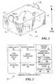
- FIG. 1is a three dimensional view of the starting aid for a lamp according to the present invention
- FIG. 2is a block diagram of the starting aid circuit according to the present invention.
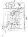
- FIG. 3is a schematic diagram of a first embodiment the starting aid according to the present invention.
- FIG. 4is a schematic diagram, similar to FIG. 3, further including a photo controller for automatically turning the lamp on and off and a lamp off circuit for shunting the lamp to turn it off;
- FIG. 5is a schematic design of a third embodiment of the invention, in which the trigger circuit includes a SIDAC circuit for turning on the lamp and a relay circuit for enabling the SIDAC;
- FIG. 6is a schematic diagram of a third embodiment of the invention, in which the relay circuit is replaced by a photocoupler for enabling the SIDAC;
- FIG. 7is a schematic diagram of a fifth embodiment of the invention.
- FIG. 8is a schematic diagram of a sixth embodiment of the invention.
- FIG. 9is a schematic diagram of a seventh embodiment of the invention.
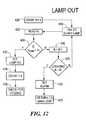
- FIG. 10is a flow chart generally showing the operation of the starting aid circuit according to the present invention.
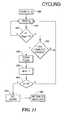
- FIG. 11is a flow chart depicting the routine for detecting a lamp out condition in accordance with the present invention.
- FIG. 12is a flow chart depicting the routine for detecting a cycling condition of the lamp in accordance with the present invention.
- Luminaire starting aid 10FIG. 1, includes thermoplastic, impact resistant, ultra violet stabilized polypropylene cover 12 and clear window 14 made from UV stabilized, UV absorbing acrylic for the light sensor, not shown, which resides on a circuit board within cover 12 .
- Luminaire starting aid 10is typically configured to fit an existing luminaire receptacle.
- Prongs 16plug into a luminaire assembly and retaining clips 18 hold device 10 in place: the device according to the present invention is mounted underneath the luminaire such that alarm LED 20 can be viewed by a worker from the ground to determine if a fault exists without having to be raised up to the lamp assembly.
- Luminaire starting circuit 22shown in block form in FIG. 2, generally includes power supply 24 , microprocessor 26 , load detection circuit 28 , trigger circuit 30 and communication device 32 , which may include both on site and offsite portion 33 a and 33 b, respectively.
- Starting circuit 22may optionally include a photocontroller 34 , a lamp off circuit 36 , a condition sensing circuit 38 including lampout device 39 a and cycling detector 39 b and diagnostic circuitry 40 .
- starting aid circuit 50The basic operation of starting aid circuit 50 , FIG. 3, is such that power supply 56 , which includes inductor L 1 , diode bridge BR 2 , resistor R 3 , capacitor C 2 and Zener diode Z 1 , delivers the necessary voltage needed for each of the sub circuits.
- Bridge BR 2(which could also be four individual diodes), R 3 , Z 1 and C 2 make up a 5 volt power supply.
- Inductor L 1is used to increase the impedance at high frequency of starting aid circuit 50 .
- Bridge BR 2rectifies the AC voltage coming from the tap of ballast 52 .
- Resistor R 3is a current limiting resistor.
- resistor R 3The value of resistor R 3 is such that it will limit the current so that microprocessor circuit 58 , alarm LED 64 , and trigger circuit 60 will receive sufficient current in order to operate normally.
- Zener diode Z 1regulates the voltage to microprocessor circuit 58 and trigger circuit 60 .
- Capacitor C 2is used to filter any AC ripple which may be present on the 5-volt line and further provides peak pulse current to trigger circuit 60 and alarm LED circuit 64 .
- microprocessor 66 of microprocessor circuit 58will wait a predetermined period of time, for example one second, before carrying out any instructions. This allows capacitor C 1 of voltage divider 62 to charge up. Thereafter, the main loop of the program is started.
- Voltage divider 62is provided in order to detect a load drawn by lamp 54 .
- Resistors R 1 and R 2make up a 100:1 voltage divider.
- the rectified voltageis thus delivered to microprocessor 66 as a sample voltage, proportional to the voltage across lamp 54 .
- Microprocessor 66uses this voltage to determine the status of lamp 54 .
- Capacitor C 1further filters the sample voltage being used by microprocessor 66 .
- Zener diode Z 2ensures that the sample voltage does not damage the input circuit of microprocessor 66 .
- a voltage readingis taken at node V 1 . When lamp 54 is off, the voltage detected at node V 1 should be proportional to the line voltage, or the highest voltage the circuit will see. This voltage is then multiplied by 0.75 to determine the trip voltage. By choosing 75% of the highest voltage, the present circuit provides a universal starting aid that can be used in conjunction with 55 volt or 100 volt lamps without modification.
- Microprocessor circuit 58includes resistor R 4 , capacitor C 3 and microprocessor 66 which may be for example, a 12C671 or a 12C672 available from Microchip of Arizona.
- Resistor R 4is a current limiting resistor which provides microprocessor 66 with a clock pulse derived from the line frequency.
- Capacitor C 3is a bypass capacitor for microprocessor 66 .
- the 12C671 (or 12C672) microprocessorhas analog to digital (A/D) capabilities. This allows the analog voltage sampling of the lamp voltage to be converted to a digital value so that microprocessor 66 can determine the status of the lamp, as described below.
- microprocessor 66sends out a pulse train to trigger circuit 60 .
- Trigger circuit 60includes resistor R 5 , transistor Q 1 , transformer T 1 , diodes D 1 and D 8 and capacitors C 4 and C 30 .
- Resistor R 5is a current limiting resistor which is used to develop the base current to turn on transistor Q 1 .
- Transistor Q 1is driven on and off by microprocessor 66 in response to pulses sent by microprocessor 66 . These pulses are coupled to lamp 54 by transformer T 1 .
- the primary winding of transformer T 1is connected between a regulated five (5) volts from power supply 56 and Q 1 . When transistor Q 1 is pulsed on, the five (5) volts is stepped up to approximately 3500 volts.
- the pulseis typically 1.5 ⁇ sec in duration and should be sufficient to start lamp 54 .
- Capacitor C 4limits the leakage current that will flow through the secondary windings of transformer T 1 .
- Microprocessor 66waits a predetermined period of time, for example two (2) seconds. A second voltage reading is taken at node V 1 . If the second voltage read at node V 1 is lower than the trip voltage which, as discussed above, is taken as 75% of the line voltage, the lamp has started. However, if the second voltage reading at node V 1 is not lower than the trip voltage, microprocessor 66 sends another pulse train to trigger circuit 60 . In the preferred embodiment, this process is repeated four more times for a total of five times.
- Alarm circuit 64includes resistor R 6 and light emitting diode D 2 .
- Resistor R 6is current limiting resistor for LED D 2 .
- LED D 2will light in response to instructions from microprocessor 66 to indicate to a line worker that lamp 54 is dead. If, on the other hand, after lamp 54 starts it is then cycled off, microprocessor 66 will wait a predetermined period of time, for example two minutes, and then try to start the lamp 54 again. This is done to prevent hot restriking of lamp 54 .
- microprocessor 66monitors the number of times the cycling occurs and limits restarting of the lamp 54 to a maximum number, for example five (5) times, in a single night. If the lamp 54 cycles the predetermined number of times, the lamp 54 will be considered faulty and LED D 2 of alarm circuit 64 will be activated.
- the systemAfter the circuit is initialized, block 400 , the system enters he main loop, block 402 . If the microprocessor 66 determines that the alarm is on, block 404 , the alarm LED is activated, block 406 , and the system returns to the main loop 402 . If the microprocessor 66 determines that the system is not in an alarm state, the system determines whether the lamp 54 is on, block 408 . If it is not, the system enters the lamp out routine, block 412 , which is shown in greater detail in FIG. 12 .
- a count Nis set to 5 during initialization.
- a pulseis sent to the lamp in order to try and start the lamp, block 410 and then the voltage at node V 1 is read, block 422 . If the voltage at node 410 is not less than the trigger voltage, block 424 , indicating the lamp has not been started, the count N is decremented by one, block 426 . If the count N is not equal to 0, block 428 , another pulse is sent to the lamp in order to attempt to start the lamp, block 410 . Again, the voltage at node V 1 is read, block 422 to determine if the lamp has been started.
- the alarmis set, block 430 and the system returns to the main loop, block 431 . If, at block 424 , the voltage at node V 1 is less than the trigger voltage, a “lamp on” flag is set, block 432 and the count N is reset to 5, block 434 . The system then checks if the lamp is cycling, block 436 . Referring back to FIG. 10, since, at block 408 , it is determined that the lamp is on, the cycling routine is run, block 414 , as shown in FIG. 11 .
- the count Nis set to 5 during initialization, block 440 , and the voltage at node V 1 is read, block 442 . If the voltage at node V 1 is less than the trigger voltage, block 444 , the system determines that the lamp is indeed on and returns to block 442 to monitor the voltage at node V 1 . If in block 444 , it is determined that the voltage at node V 1 is not less than the trigger voltage, the system determines whether a predetermined period of time in minutes has passed, block 446 . If it has not, the system returns to block 442 and continues to monitor the voltage at node V 1 .
- Starting aid circuit 100includes a photo control circuit 102 for turning lamp 54 on during nighttime hours and off during daytime hours.
- Photo control circuit 102includes resistors R 17 , R 18 , and R 19 and transistor Q 2 .
- Resistors R 17 , R 18 and R 19are used as calibration resistors. These resistors may be snapped out of the circuit 100 to lower the calibration point to ensure that the microprocessor 66 turns the lamp 54 on at the correct light level.
- Transistor Q 2is a light sensing device, for example a phototransistor, that conducts proportionally to the light level it detects. This produces a voltage which is input to A/D pin 70 of microprocessor 66 .
- Lamp off circuit 104includes transformer T 2 , resistor R 10 , and TRIAC X 2 . Lamp off circuit 104 turns lamp 54 off by placing a short across, or shunting the lamp.
- Transformer T 2is an isolation transformer and is needed since microprocessor 66 is not referenced to neutral as the lamp 54 is.
- Resistor R 10is a biasing resistor for TRIAC X 2 . A resistor or some other current limiting device may also be placed in line with TRIAC X 2 .
- Staring aid circuit 150includes relay trigger circuit 152 which includes relay K 1 to enable SIDAC trigger circuit 154 .
- the primary difference between trigger circuit 154 and trigger circuit 60is that, rather than a pulse train being sent by microprocessor 66 , a single pulse of a duration of 2 seconds is used to energize relay K 1 .
- Resistor R 5 , transistor Q 1 , diode D 1 and relay K 1are used to enable SIDAC circuit 154 which includes SIDAC 156 , inductor L 10 , capacitor C 24 and resistor R 16 .
- Resistor R 5is a current limiting resistor which develops the base current for transistor Q 1 which energizes relay K 1 .
- Diode D 10operates as a back swing clipping diode intended to eliminate voltage spikes developed by relay K 1 when the relay is de-energized.
- SIDAC circuit 154When relay K 1 is energized, SIDAC circuit 154 is enabled and lamp 54 will start. When relay K 1 is de-energized, the lamp will not be triggered. This circuit 154 represents a traditional starting aid trigger circuit.
- the SIDAC 156has high resistance until a specified voltage is reached, in which case it has low resistance.
- Indicator L 1is used to dampen the voltage spike that will be developed by C 4 , the ballast and the SIDAC.
- R 6is a current limit resistor.
- SIDAC 156When relay K 1 is energized, SIDAC 156 will switch from a high resistance to low resistance. Capacitor C 24 discharges through ballast 52 and a voltage spike is seen by lamp 54 . This occurs every one-half cycle. When the voltage seen by SIDAC 156 drops below a specified voltage, SIDAC 156 returns to a high resistance state. When relay 156 is de-energized, there is no current path back to the SIDAC 156 and thus trigger circuit 154 is disabled.
- FIG. 6Another embodiment of the invention is shown at 200 in FIG. 6 .
- Starting aid circuit 200includes power supply 56 with the addition of resistor R 7 which limits current and further helps prevent any transient voltage or current spikes from entering the rest of the circuit.
- opto-coupler circuit 204which includes resistors R 25 and R 28 , transistor Q 2 , and opto-coupler circuit 206 , which provide a switch to turn on the circuit 202 .
- Resistor R 25is a current limiting resistor that provides base current to transistor Q 20 .
- Transistor Q 20enables opto-coupler 206 .
- Transistor Q 20is driven in response to microprocessor 66 to light LED 208 within opto-coupler 206 .
- Resistor R 28limits the current to LED 208 .
- the light produced by LED 208causes opto-coupler 206 to conduct.
- SIDAC circuit 202When opto-coupler U 2 is conducting, SIDAC circuit 202 is enabled, lighting lamp 54 .
- Starting aid circuit 250is identical to starting aid circuit 200 , FIG. 6, except for the opto-coupler circuit 254 , which includes a diode D 5 and phototransistor Q 30 for enabling SIDAC circuit 202 .
- FIG. 8Another embodiment of the invention is shown at 300 in FIG. 8 .
- Starting aid circuit 300includes power supply 302 which is a half wave power supply.
- Power supply 302as compared to power supply 56 , FIG. 7, provides half wave rectification.
- Resistor R 7 and capacitor C 5serve to limit current while diode D 3 serves as a blocking diode.
- Zener diode Z 1 , resistor R 3 and capacitor C 2operate in the same manner as in power supply 56 , FIG. 7 .
- capacitor C 2has much larger capacitance in order to provide the same filtering.
- Trigger circuit 306includes resistors R 15 and R 13 , capacitor C 6 , and TRIAC X 1 .
- Resistors R 15 and R 13 and capacitor C 6are pulse conditioning components. When TRIAC X 1 receives a pulse at its gate, it will to enable SIDAC circuit 202 .
- the advantage of starting aid circuit 300is that because halfwave rectification is be used, opto-couplers or isolation transformers are no longer needed.
- Lamp off circuit 304includes relay 308 , resistors R 5 and R 12 , and transistor Q 3 . Resistor R 5 and transistor Q 3 drive relay 308 on and off in response to microprocessor 66 , and relay 308 turns lamp 54 on and off. When relay 308 is energized, a short circuit is placed across lamp 54 , extinguishing the lamp.
- This circuitalso includes photo control circuit 30 , similar to photocontrol circuit 102 , FIG. 4 . Cycling detection may also be included to determine if the lamp is cycling or off due to lighting conditions.
- Starting aid circuit 350includes lamp off circuit 352 comprised of resistors R 12 , and 14 , capacitor C 7 and TRIAC X 2 . Because power supply 302 provides half wave rectification, no isolation transformer is required as shown in circuit 300 of FIG. 8 .
Landscapes
- Circuit Arrangement For Electric Light Sources In General (AREA)
- Circuit Arrangements For Discharge Lamps (AREA)
Abstract
Description
Claims (47)
Priority Applications (4)
| Application Number | Priority Date | Filing Date | Title |
|---|---|---|---|
| US09/544,307US6452340B1 (en) | 1999-04-09 | 2000-04-06 | Luminaire starting aid device |
| CA002304911ACA2304911C (en) | 1999-04-09 | 2000-04-07 | Luminaire starting aid device |
| EP00303012AEP1043917A3 (en) | 1999-04-09 | 2000-04-10 | Luminaire starting aid device |
| MXPA00003499AMXPA00003499A (en) | 1999-04-09 | 2000-04-10 | Luminaire starting aid device. |
Applications Claiming Priority (2)
| Application Number | Priority Date | Filing Date | Title |
|---|---|---|---|
| US12863599P | 1999-04-09 | 1999-04-09 | |
| US09/544,307US6452340B1 (en) | 1999-04-09 | 2000-04-06 | Luminaire starting aid device |
Publications (1)
| Publication Number | Publication Date |
|---|---|
| US6452340B1true US6452340B1 (en) | 2002-09-17 |
Family
ID=26826786
Family Applications (1)
| Application Number | Title | Priority Date | Filing Date |
|---|---|---|---|
| US09/544,307Expired - LifetimeUS6452340B1 (en) | 1999-04-09 | 2000-04-06 | Luminaire starting aid device |
Country Status (4)
| Country | Link |
|---|---|
| US (1) | US6452340B1 (en) |
| EP (1) | EP1043917A3 (en) |
| CA (1) | CA2304911C (en) |
| MX (1) | MXPA00003499A (en) |
Cited By (40)
| Publication number | Priority date | Publication date | Assignee | Title |
|---|---|---|---|---|
| US20040124786A1 (en)* | 2000-08-22 | 2004-07-01 | Morrissey Jr Joseph F. | Luminaire diagnostic and configuration identification system |
| US20040189479A1 (en)* | 2001-05-03 | 2004-09-30 | Tewell Tony J. | Warning device status circuit including a status output device |
| US20040188593A1 (en)* | 2003-03-20 | 2004-09-30 | Patrick Mullins | Photosensor control unit |
| US7164359B2 (en)* | 2003-04-09 | 2007-01-16 | Visible Assets, Inc | Networked RF tag for tracking freight |
| US20070080650A1 (en)* | 2003-04-30 | 2007-04-12 | Tridonicatco Gmbh & Co. Kg | Starter circuit having regulated starter voltage |
| US20070152825A1 (en)* | 2003-04-09 | 2007-07-05 | Visible Assets, Inc. | Networked RF tag for tracking baggage |
| US20070152826A1 (en)* | 2003-04-09 | 2007-07-05 | Visible Assets, Inc. | Networked RF tag for tracking baggage |
| US20080218348A1 (en)* | 2006-04-12 | 2008-09-11 | Visible Assets Inc. | Visibility radio cap and network |
| US20090045965A1 (en)* | 2003-04-09 | 2009-02-19 | Visible Assets, Inc. | Networked RF tag for tracking baggage |
| US20090058646A1 (en)* | 2003-04-09 | 2009-03-05 | Visible Assets, Inc. | Networked RF tag for tracking baggage |
| US20090160620A1 (en)* | 2003-04-09 | 2009-06-25 | Visible Assets Inc. | Smartbeam Visibility Network |
| US7569802B1 (en) | 2003-03-20 | 2009-08-04 | Patrick Mullins | Photosensor control unit for a lighting module |
| US20090212117A1 (en)* | 2003-04-09 | 2009-08-27 | Visible Assets Inc. | Networked Loyalty Cards |
| US20100245279A1 (en)* | 2009-03-31 | 2010-09-30 | Robe Lighting S.R.O. | Display and display control system for an automated luminaire |
| US20110163882A1 (en)* | 2003-04-09 | 2011-07-07 | Visible Assets, Inc. | Passive Low Frequency Inductive Tagging |
| US20110163857A1 (en)* | 2003-04-09 | 2011-07-07 | Visible Assets, Inc. | Energy Harvesting for Low Frequency Inductive Tagging |
| US8072223B1 (en)* | 2011-07-31 | 2011-12-06 | Sioma Edward M | Monitoring circuit for determining if an electric element has failed before the electric element is powered |
| US8378841B2 (en) | 2003-04-09 | 2013-02-19 | Visible Assets, Inc | Tracking of oil drilling pipes and other objects |
| US8681000B2 (en) | 2003-04-09 | 2014-03-25 | Visible Assets, Inc. | Low frequency inductive tagging for lifecycle management |
| US8805550B2 (en) | 2008-04-14 | 2014-08-12 | Digital Lumens Incorporated | Power management unit with power source arbitration |
| US8823277B2 (en) | 2008-04-14 | 2014-09-02 | Digital Lumens Incorporated | Methods, systems, and apparatus for mapping a network of lighting fixtures with light module identification |
| US8841859B2 (en) | 2008-04-14 | 2014-09-23 | Digital Lumens Incorporated | LED lighting methods, apparatus, and systems including rules-based sensor data logging |
| US8866408B2 (en) | 2008-04-14 | 2014-10-21 | Digital Lumens Incorporated | Methods, apparatus, and systems for automatic power adjustment based on energy demand information |
| US8884532B2 (en) | 2012-05-25 | 2014-11-11 | Ripley Lighting Controls, LLC | Photo control for a luminaire |
| US20140340097A1 (en)* | 2013-05-20 | 2014-11-20 | Lsis Co., Ltd. | Method of detecting state of power cable in inverter system |
| US8954170B2 (en) | 2009-04-14 | 2015-02-10 | Digital Lumens Incorporated | Power management unit with multi-input arbitration |
| US9014829B2 (en) | 2010-11-04 | 2015-04-21 | Digital Lumens, Inc. | Method, apparatus, and system for occupancy sensing |
| US9069933B1 (en) | 2005-09-28 | 2015-06-30 | Visible Assets, Inc. | Secure, networked portable storage device |
| US9072133B2 (en) | 2008-04-14 | 2015-06-30 | Digital Lumens, Inc. | Lighting fixtures and methods of commissioning lighting fixtures |
| US9241392B2 (en) | 2012-03-19 | 2016-01-19 | Digital Lumens, Inc. | Methods, systems, and apparatus for providing variable illumination |
| CN106154110A (en)* | 2016-06-21 | 2016-11-23 | 泰华智慧产业集团股份有限公司 | The method carrying out the roads light monitoring of fault location based on detection of electrical leakage |
| US9510426B2 (en) | 2011-11-03 | 2016-11-29 | Digital Lumens, Inc. | Methods, systems, and apparatus for intelligent lighting |
| US9924576B2 (en) | 2013-04-30 | 2018-03-20 | Digital Lumens, Inc. | Methods, apparatuses, and systems for operating light emitting diodes at low temperature |
| US10057964B2 (en) | 2015-07-02 | 2018-08-21 | Hayward Industries, Inc. | Lighting system for an environment and a control module for use therein |
| US10230634B2 (en) | 2015-09-25 | 2019-03-12 | Osram Sylvania Inc. | Route optimization using star-mesh hybrid topology in localized dense ad-hoc networks |
| US10264652B2 (en) | 2013-10-10 | 2019-04-16 | Digital Lumens, Inc. | Methods, systems, and apparatus for intelligent lighting |
| US10485068B2 (en) | 2008-04-14 | 2019-11-19 | Digital Lumens, Inc. | Methods, apparatus, and systems for providing occupancy-based variable lighting |
| US10499487B2 (en) | 2015-10-05 | 2019-12-03 | Scalia Lighting Technologies LLC | Light-emitting diode (LED) lighting fixture solutions and methods |
| US10891881B2 (en) | 2012-07-30 | 2021-01-12 | Ultravision Technologies, Llc | Lighting assembly with LEDs and optical elements |
| US12231337B2 (en) | 2015-09-25 | 2025-02-18 | Digital Lumens Incorporated | Route optimization using star-mesh hybrid topology in localized dense ad-hoc networks |
Families Citing this family (4)
| Publication number | Priority date | Publication date | Assignee | Title |
|---|---|---|---|---|
| IL138896A0 (en)* | 2000-10-05 | 2001-11-25 | Hashofet Eltam Ein | An ignitor for discharge lamps |
| GB2377987B (en)* | 2001-07-24 | 2003-10-22 | Martech Uk Ltd | Improvement to lighting installations |
| WO2004064455A1 (en)* | 2003-01-14 | 2004-07-29 | Koninklijke Philips Electronics N.V. | Circuit and method for providing power to a load, especially a high-intensity discharge lamp |
| TWI795884B (en) | 2021-08-25 | 2023-03-11 | 立積電子股份有限公司 | Device of measuring duty cycle and compensation circuit |
Citations (13)
| Publication number | Priority date | Publication date | Assignee | Title |
|---|---|---|---|---|
| US4396872A (en)* | 1981-03-30 | 1983-08-02 | General Mills, Inc. | Ballast circuit and method for optimizing the operation of high intensity discharge lamps in the growing of plants |
| US4473779A (en)* | 1982-05-26 | 1984-09-25 | Area Lighting Research, Inc. | Power factor measuring cut-off arrangement for and method of protecting a ballast-starter circuit from high pressure sodium lamp cycling malfunction |
| CA1205853A (en) | 1982-05-05 | 1986-06-10 | Gregory L. Sodini | Electronic lamp control apparatus |
| US5095502A (en)* | 1987-12-04 | 1992-03-10 | Finzel Jean Luc | System for the detection and localization of defective lamps of an urban lighting network |
| US5223795A (en)* | 1992-07-30 | 1993-06-29 | Blades Frederick K | Method and apparatus for detecting arcing in electrical connections by monitoring high frequency noise |
| US5397963A (en)* | 1993-09-02 | 1995-03-14 | New Bedford Panoramex Corporation | Subsystem and method for detecting lamp failure |
| US5463287A (en) | 1993-10-06 | 1995-10-31 | Tdk Corporation | Discharge lamp lighting apparatus which can control a lighting process |
| US5569984A (en)* | 1994-12-28 | 1996-10-29 | Philips Electronics North America Corporation | Method and controller for detecting arc instabilities in gas discharge lamps |
| US5677602A (en)* | 1995-05-26 | 1997-10-14 | Paul; Jon D. | High efficiency electronic ballast for high intensity discharge lamps |
| US5801494A (en)* | 1996-05-21 | 1998-09-01 | Cooper Industries, Inc. | Rapid restrike with integral cutout timer |
| US5821700A (en)* | 1996-12-20 | 1998-10-13 | Star Headlight & Lantern Co. | Visual warning system for a railway vehicle |
| US6028396A (en)* | 1997-08-19 | 2000-02-22 | Dark To Light | Luminaire diagnostic system |
| US6119076A (en)* | 1997-04-16 | 2000-09-12 | A.L. Air Data, Inc. | Lamp monitoring and control unit and method |
Family Cites Families (5)
| Publication number | Priority date | Publication date | Assignee | Title |
|---|---|---|---|---|
| US4207500A (en)* | 1978-12-14 | 1980-06-10 | Area Lighting Research, Inc. | Cut-off arrangement for and method of protecting a ballast-starter circuit from high pressure sodium lamp cycling malfunction |
| US4896077A (en)* | 1987-06-16 | 1990-01-23 | Cooper Industries, Inc. | Ignitor disabler |
| US5103137A (en)* | 1990-04-02 | 1992-04-07 | Multipoint Control Systems, Inc. | Anti-cycling device for high pressure sodium lamps |
| US5424617A (en)* | 1993-02-26 | 1995-06-13 | North American Philips Corporation | HID lamp ignitor-timer with automatic reset for dips in line voltage |
| WO1998002859A1 (en)* | 1996-07-12 | 1998-01-22 | Mew, Jeanette | Improvements in and relating to remote monitoring and signalling |
- 2000
- 2000-04-06USUS09/544,307patent/US6452340B1/ennot_activeExpired - Lifetime
- 2000-04-07CACA002304911Apatent/CA2304911C/ennot_activeExpired - Lifetime
- 2000-04-10MXMXPA00003499Apatent/MXPA00003499A/enactiveIP Right Grant
- 2000-04-10EPEP00303012Apatent/EP1043917A3/ennot_activeWithdrawn
Patent Citations (13)
| Publication number | Priority date | Publication date | Assignee | Title |
|---|---|---|---|---|
| US4396872A (en)* | 1981-03-30 | 1983-08-02 | General Mills, Inc. | Ballast circuit and method for optimizing the operation of high intensity discharge lamps in the growing of plants |
| CA1205853A (en) | 1982-05-05 | 1986-06-10 | Gregory L. Sodini | Electronic lamp control apparatus |
| US4473779A (en)* | 1982-05-26 | 1984-09-25 | Area Lighting Research, Inc. | Power factor measuring cut-off arrangement for and method of protecting a ballast-starter circuit from high pressure sodium lamp cycling malfunction |
| US5095502A (en)* | 1987-12-04 | 1992-03-10 | Finzel Jean Luc | System for the detection and localization of defective lamps of an urban lighting network |
| US5223795A (en)* | 1992-07-30 | 1993-06-29 | Blades Frederick K | Method and apparatus for detecting arcing in electrical connections by monitoring high frequency noise |
| US5397963A (en)* | 1993-09-02 | 1995-03-14 | New Bedford Panoramex Corporation | Subsystem and method for detecting lamp failure |
| US5463287A (en) | 1993-10-06 | 1995-10-31 | Tdk Corporation | Discharge lamp lighting apparatus which can control a lighting process |
| US5569984A (en)* | 1994-12-28 | 1996-10-29 | Philips Electronics North America Corporation | Method and controller for detecting arc instabilities in gas discharge lamps |
| US5677602A (en)* | 1995-05-26 | 1997-10-14 | Paul; Jon D. | High efficiency electronic ballast for high intensity discharge lamps |
| US5801494A (en)* | 1996-05-21 | 1998-09-01 | Cooper Industries, Inc. | Rapid restrike with integral cutout timer |
| US5821700A (en)* | 1996-12-20 | 1998-10-13 | Star Headlight & Lantern Co. | Visual warning system for a railway vehicle |
| US6119076A (en)* | 1997-04-16 | 2000-09-12 | A.L. Air Data, Inc. | Lamp monitoring and control unit and method |
| US6028396A (en)* | 1997-08-19 | 2000-02-22 | Dark To Light | Luminaire diagnostic system |
Cited By (67)
| Publication number | Priority date | Publication date | Assignee | Title |
|---|---|---|---|---|
| US6841944B2 (en) | 2000-08-22 | 2005-01-11 | Acuity Brands, Inc. | Luminaire diagnostic and configuration identification system |
| US20040124786A1 (en)* | 2000-08-22 | 2004-07-01 | Morrissey Jr Joseph F. | Luminaire diagnostic and configuration identification system |
| US20040189479A1 (en)* | 2001-05-03 | 2004-09-30 | Tewell Tony J. | Warning device status circuit including a status output device |
| US7023353B2 (en)* | 2001-05-03 | 2006-04-04 | Electronic Controls Company | Warning device status circuit including a status output device |
| US7569802B1 (en) | 2003-03-20 | 2009-08-04 | Patrick Mullins | Photosensor control unit for a lighting module |
| US20040188593A1 (en)* | 2003-03-20 | 2004-09-30 | Patrick Mullins | Photosensor control unit |
| US7663494B2 (en) | 2003-04-09 | 2010-02-16 | Visible Assets, Inc | Networked RF tag for tracking people by means of loyalty cards |
| US7911344B2 (en) | 2003-04-09 | 2011-03-22 | Visible Assets, Inc. | Smartbeam visibility network |
| US20070152824A1 (en)* | 2003-04-09 | 2007-07-05 | Paul Waterhouse | Networked rf tag for tracking animals |
| US20070152825A1 (en)* | 2003-04-09 | 2007-07-05 | Visible Assets, Inc. | Networked RF tag for tracking baggage |
| US20070152826A1 (en)* | 2003-04-09 | 2007-07-05 | Visible Assets, Inc. | Networked RF tag for tracking baggage |
| US7277014B1 (en) | 2003-04-09 | 2007-10-02 | Visible Assets, Inc. | Networked RF tag for tracking animals |
| US8681000B2 (en) | 2003-04-09 | 2014-03-25 | Visible Assets, Inc. | Low frequency inductive tagging for lifecycle management |
| US8378841B2 (en) | 2003-04-09 | 2013-02-19 | Visible Assets, Inc | Tracking of oil drilling pipes and other objects |
| US7489245B2 (en) | 2003-04-09 | 2009-02-10 | Visible Assets, Inc | Networked RF tag for tracking baggage |
| US7489244B2 (en) | 2003-04-09 | 2009-02-10 | Visible Assets, Inc. | Networked RF tag for tracking baggage |
| US20090045965A1 (en)* | 2003-04-09 | 2009-02-19 | Visible Assets, Inc. | Networked RF tag for tracking baggage |
| US20090058646A1 (en)* | 2003-04-09 | 2009-03-05 | Visible Assets, Inc. | Networked RF tag for tracking baggage |
| US20090160620A1 (en)* | 2003-04-09 | 2009-06-25 | Visible Assets Inc. | Smartbeam Visibility Network |
| US7170413B1 (en) | 2003-04-09 | 2007-01-30 | Visible Assets, Inc. | Networked RF tag for tracking animals |
| US20090212117A1 (en)* | 2003-04-09 | 2009-08-27 | Visible Assets Inc. | Networked Loyalty Cards |
| US8714457B2 (en) | 2003-04-09 | 2014-05-06 | Visible Assets, Inc. | Networked loyalty cards |
| US7675422B2 (en) | 2003-04-09 | 2010-03-09 | Visible Assets, Inc. | Networked RF Tag for tracking people by means of loyalty cards |
| US7164359B2 (en)* | 2003-04-09 | 2007-01-16 | Visible Assets, Inc | Networked RF tag for tracking freight |
| US20110163857A1 (en)* | 2003-04-09 | 2011-07-07 | Visible Assets, Inc. | Energy Harvesting for Low Frequency Inductive Tagging |
| US20110163882A1 (en)* | 2003-04-09 | 2011-07-07 | Visible Assets, Inc. | Passive Low Frequency Inductive Tagging |
| US20070080650A1 (en)* | 2003-04-30 | 2007-04-12 | Tridonicatco Gmbh & Co. Kg | Starter circuit having regulated starter voltage |
| US7462992B2 (en) | 2003-04-30 | 2008-12-09 | Tridonicatco Gmbh & Co. Kg | Starter circuit having regulated starter voltage |
| US9069933B1 (en) | 2005-09-28 | 2015-06-30 | Visible Assets, Inc. | Secure, networked portable storage device |
| US7864053B2 (en) | 2006-04-12 | 2011-01-04 | Visible Assets, Inc. | Visibility radio cap and network |
| US20080218348A1 (en)* | 2006-04-12 | 2008-09-11 | Visible Assets Inc. | Visibility radio cap and network |
| US8805550B2 (en) | 2008-04-14 | 2014-08-12 | Digital Lumens Incorporated | Power management unit with power source arbitration |
| US9860961B2 (en) | 2008-04-14 | 2018-01-02 | Digital Lumens Incorporated | Lighting fixtures and methods via a wireless network having a mesh network topology |
| US8823277B2 (en) | 2008-04-14 | 2014-09-02 | Digital Lumens Incorporated | Methods, systems, and apparatus for mapping a network of lighting fixtures with light module identification |
| US8841859B2 (en) | 2008-04-14 | 2014-09-23 | Digital Lumens Incorporated | LED lighting methods, apparatus, and systems including rules-based sensor data logging |
| US8866408B2 (en) | 2008-04-14 | 2014-10-21 | Digital Lumens Incorporated | Methods, apparatus, and systems for automatic power adjustment based on energy demand information |
| US11193652B2 (en) | 2008-04-14 | 2021-12-07 | Digital Lumens Incorporated | Lighting fixtures and methods of commissioning light fixtures |
| US10539311B2 (en) | 2008-04-14 | 2020-01-21 | Digital Lumens Incorporated | Sensor-based lighting methods, apparatus, and systems |
| US10485068B2 (en) | 2008-04-14 | 2019-11-19 | Digital Lumens, Inc. | Methods, apparatus, and systems for providing occupancy-based variable lighting |
| US10362658B2 (en) | 2008-04-14 | 2019-07-23 | Digital Lumens Incorporated | Lighting fixtures and methods for automated operation of lighting fixtures via a wireless network having a mesh network topology |
| US9072133B2 (en) | 2008-04-14 | 2015-06-30 | Digital Lumens, Inc. | Lighting fixtures and methods of commissioning lighting fixtures |
| US9125254B2 (en) | 2008-04-14 | 2015-09-01 | Digital Lumens, Inc. | Lighting fixtures and methods of commissioning lighting fixtures |
| US20100245279A1 (en)* | 2009-03-31 | 2010-09-30 | Robe Lighting S.R.O. | Display and display control system for an automated luminaire |
| US8954170B2 (en) | 2009-04-14 | 2015-02-10 | Digital Lumens Incorporated | Power management unit with multi-input arbitration |
| US9014829B2 (en) | 2010-11-04 | 2015-04-21 | Digital Lumens, Inc. | Method, apparatus, and system for occupancy sensing |
| US9915416B2 (en) | 2010-11-04 | 2018-03-13 | Digital Lumens Inc. | Method, apparatus, and system for occupancy sensing |
| US8072223B1 (en)* | 2011-07-31 | 2011-12-06 | Sioma Edward M | Monitoring circuit for determining if an electric element has failed before the electric element is powered |
| US10306733B2 (en) | 2011-11-03 | 2019-05-28 | Digital Lumens, Inc. | Methods, systems, and apparatus for intelligent lighting |
| US9510426B2 (en) | 2011-11-03 | 2016-11-29 | Digital Lumens, Inc. | Methods, systems, and apparatus for intelligent lighting |
| US9241392B2 (en) | 2012-03-19 | 2016-01-19 | Digital Lumens, Inc. | Methods, systems, and apparatus for providing variable illumination |
| US9832832B2 (en) | 2012-03-19 | 2017-11-28 | Digital Lumens, Inc. | Methods, systems, and apparatus for providing variable illumination |
| US8884532B2 (en) | 2012-05-25 | 2014-11-11 | Ripley Lighting Controls, LLC | Photo control for a luminaire |
| US10891881B2 (en) | 2012-07-30 | 2021-01-12 | Ultravision Technologies, Llc | Lighting assembly with LEDs and optical elements |
| US9924576B2 (en) | 2013-04-30 | 2018-03-20 | Digital Lumens, Inc. | Methods, apparatuses, and systems for operating light emitting diodes at low temperature |
| US20140340097A1 (en)* | 2013-05-20 | 2014-11-20 | Lsis Co., Ltd. | Method of detecting state of power cable in inverter system |
| US9400303B2 (en)* | 2013-05-20 | 2016-07-26 | Lsis Co., Ltd. | Method of detecting state of power cable in inverter system |
| CN104181472A (en)* | 2013-05-20 | 2014-12-03 | Ls产电株式会社 | Method of detecting state of power cable in inverter system |
| US10264652B2 (en) | 2013-10-10 | 2019-04-16 | Digital Lumens, Inc. | Methods, systems, and apparatus for intelligent lighting |
| US10588200B2 (en) | 2015-07-02 | 2020-03-10 | Hayward Industries, Inc. | Lighting system for an environment and a control module for use therein |
| US10057964B2 (en) | 2015-07-02 | 2018-08-21 | Hayward Industries, Inc. | Lighting system for an environment and a control module for use therein |
| US11632835B2 (en) | 2015-07-02 | 2023-04-18 | Hayward Industries, Inc. | Lighting system for an environment and a control module for use therein |
| US12273972B2 (en) | 2015-07-02 | 2025-04-08 | Hayward Industries, Inc. | Lighting system for an environment and a control module for use therein |
| US10230634B2 (en) | 2015-09-25 | 2019-03-12 | Osram Sylvania Inc. | Route optimization using star-mesh hybrid topology in localized dense ad-hoc networks |
| US11575603B2 (en) | 2015-09-25 | 2023-02-07 | Digital Lumens Incorporated | Route optimization using star-mesh hybrid topology in localized dense ad-hoc networks |
| US12231337B2 (en) | 2015-09-25 | 2025-02-18 | Digital Lumens Incorporated | Route optimization using star-mesh hybrid topology in localized dense ad-hoc networks |
| US10499487B2 (en) | 2015-10-05 | 2019-12-03 | Scalia Lighting Technologies LLC | Light-emitting diode (LED) lighting fixture solutions and methods |
| CN106154110A (en)* | 2016-06-21 | 2016-11-23 | 泰华智慧产业集团股份有限公司 | The method carrying out the roads light monitoring of fault location based on detection of electrical leakage |
Also Published As
| Publication number | Publication date |
|---|---|
| EP1043917A3 (en) | 2002-07-03 |
| MXPA00003499A (en) | 2002-03-08 |
| EP1043917A2 (en) | 2000-10-11 |
| CA2304911C (en) | 2005-12-27 |
| CA2304911A1 (en) | 2000-10-09 |
Similar Documents
| Publication | Publication Date | Title |
|---|---|---|
| US6452340B1 (en) | Luminaire starting aid device | |
| US6028396A (en) | Luminaire diagnostic system | |
| US6452339B1 (en) | Photocontroller diagnostic system | |
| US6841944B2 (en) | Luminaire diagnostic and configuration identification system | |
| CA2315107C (en) | Microprocessor controlled electronic ballast | |
| CN1164149C (en) | Power supply for feeding and igniting a gas discharge lamp | |
| US7474063B2 (en) | Anti-cycling control system for luminaires | |
| US4323820A (en) | Emergency lighting system | |
| CA2193475A1 (en) | Fluorescent tube control | |
| US4896077A (en) | Ignitor disabler | |
| KR20100016599A (en) | Bulb type detector for dimmer circuit and resistance and short circuit detection | |
| EP1274286A1 (en) | Emergency lighting apparatus | |
| US6703795B2 (en) | Auxiliary controller | |
| KR20090057313A (en) | Ballast with frequency diagnostic lamp fault protection circuit | |
| WO2011009187A1 (en) | Control switch suitable for different loads | |
| MXPA04002360A (en) | Transient detection of end of lamp life condition apparatus and method. | |
| US5103137A (en) | Anti-cycling device for high pressure sodium lamps | |
| US20040113566A1 (en) | Sensing voltage for fluorescent lamp protection | |
| US20020190720A1 (en) | System for testing the presence of an ignitor pulse within a high intensity discharge luminaire | |
| US6429597B1 (en) | Externally mountable discharge lamp ignition circuit having visual diagnostic indicator | |
| NO323465B1 (en) | Method and circuit for igniting a high-pressure gas discharge lamp | |
| KR100395348B1 (en) | multi function stability apparatuse addition short detection circuit | |
| CA2315500C (en) | Photocontroller diagnostic system | |
| KR20060077185A (en) | Energy-saving magnetic ballast with adjustable dimming | |
| JPH06251881A (en) | Discharge lamp lighting device and lighting device using the same |
Legal Events
| Date | Code | Title | Description |
|---|---|---|---|
| AS | Assignment | Owner name:THOMAS & BETTS INTERNATIONAL, INC., NEVADA Free format text:ASSIGNMENT OF ASSIGNORS INTEREST;ASSIGNORS:MORRISSEY, JOSEPH F., JR.;WALTERS, JEFF;REEL/FRAME:010724/0762;SIGNING DATES FROM 20000405 TO 20000406 | |
| AS | Assignment | Owner name:ACUITY BRANDS, INC., GEORGIA Free format text:CHANGE OF NAME;ASSIGNOR:L & C SPINCO, INC.;REEL/FRAME:012985/0791 Effective date:20011109 | |
| STCF | Information on status: patent grant | Free format text:PATENTED CASE | |
| FPAY | Fee payment | Year of fee payment:4 | |
| AS | Assignment | Owner name:ABL IP HOLDING, LLC, GEORGIA Free format text:ASSIGNMENT OF ASSIGNORS INTEREST;ASSIGNOR:ACUITY BRANDS, INC;REEL/FRAME:023127/0378 Effective date:20070926 Owner name:ABL IP HOLDING, LLC,GEORGIA Free format text:ASSIGNMENT OF ASSIGNORS INTEREST;ASSIGNOR:ACUITY BRANDS, INC;REEL/FRAME:023127/0378 Effective date:20070926 | |
| FPAY | Fee payment | Year of fee payment:8 | |
| FPAY | Fee payment | Year of fee payment:12 |