US6451233B1 - Method of making a multiple foam interior trim substrate - Google Patents
Method of making a multiple foam interior trim substrateDownload PDFInfo
- Publication number
- US6451233B1 US6451233B1US09/561,002US56100200AUS6451233B1US 6451233 B1US6451233 B1US 6451233B1US 56100200 AUS56100200 AUS 56100200AUS 6451233 B1US6451233 B1US 6451233B1
- Authority
- US
- United States
- Prior art keywords
- foam
- mold
- substrate
- mold cavity
- injecting
- Prior art date
- Legal status (The legal status is an assumption and is not a legal conclusion. Google has not performed a legal analysis and makes no representation as to the accuracy of the status listed.)
- Expired - Fee Related
Links
- 239000006260foamSubstances0.000titleclaimsabstractdescription142
- 239000000758substrateSubstances0.000titleclaimsabstractdescription54
- 238000004519manufacturing processMethods0.000titleclaimsabstractdescription18
- 238000000034methodMethods0.000claimsabstractdescription44
- 238000010521absorption reactionMethods0.000claimsdescription13
- JOYRKODLDBILNP-UHFFFAOYSA-NEthyl urethaneChemical compoundCCOC(N)=OJOYRKODLDBILNP-UHFFFAOYSA-N0.000claimsdescription10
- 239000004616structural foamSubstances0.000claimsdescription8
- 238000010438heat treatmentMethods0.000claimsdescription6
- 229920005830Polyurethane FoamPolymers0.000claimsdescription4
- 239000011496polyurethane foamSubstances0.000claimsdescription4
- 229920002635polyurethanePolymers0.000claimsdescription3
- 239000004814polyurethaneSubstances0.000claimsdescription3
- 239000000463materialSubstances0.000description8
- 239000002184metalSubstances0.000description8
- 229910052751metalInorganic materials0.000description8
- 239000004744fabricSubstances0.000description4
- 238000002347injectionMethods0.000description4
- 239000007924injectionSubstances0.000description4
- 239000013518molded foamSubstances0.000description4
- 230000000704physical effectEffects0.000description3
- 239000012530fluidSubstances0.000description2
- 239000012948isocyanateSubstances0.000description2
- 150000002513isocyanatesChemical class0.000description2
- 229920005862polyolPolymers0.000description2
- 150000003077polyolsChemical class0.000description2
- 239000000853adhesiveSubstances0.000description1
- 230000001070adhesive effectEffects0.000description1
- 239000011324beadSubstances0.000description1
- -1e.g.Substances0.000description1
- 239000003292glueSubstances0.000description1
- 230000007246mechanismEffects0.000description1
- 150000002739metalsChemical class0.000description1
- 239000000203mixtureSubstances0.000description1
- 238000009428plumbingMethods0.000description1
- 239000007921spraySubstances0.000description1
Images


Classifications
- B—PERFORMING OPERATIONS; TRANSPORTING
- B60—VEHICLES IN GENERAL
- B60R—VEHICLES, VEHICLE FITTINGS, OR VEHICLE PARTS, NOT OTHERWISE PROVIDED FOR
- B60R21/00—Arrangements or fittings on vehicles for protecting or preventing injuries to occupants or pedestrians in case of accidents or other traffic risks
- B60R21/02—Occupant safety arrangements or fittings, e.g. crash pads
- B60R21/16—Inflatable occupant restraints or confinements designed to inflate upon impact or impending impact, e.g. air bags
- B60R21/20—Arrangements for storing inflatable members in their non-use or deflated condition; Arrangement or mounting of air bag modules or components
- B60R21/213—Arrangements for storing inflatable members in their non-use or deflated condition; Arrangement or mounting of air bag modules or components in vehicle roof frames or pillars
- B—PERFORMING OPERATIONS; TRANSPORTING
- B29—WORKING OF PLASTICS; WORKING OF SUBSTANCES IN A PLASTIC STATE IN GENERAL
- B29C—SHAPING OR JOINING OF PLASTICS; SHAPING OF MATERIAL IN A PLASTIC STATE, NOT OTHERWISE PROVIDED FOR; AFTER-TREATMENT OF THE SHAPED PRODUCTS, e.g. REPAIRING
- B29C44/00—Shaping by internal pressure generated in the material, e.g. swelling or foaming ; Producing porous or cellular expanded plastics articles
- B29C44/02—Shaping by internal pressure generated in the material, e.g. swelling or foaming ; Producing porous or cellular expanded plastics articles for articles of definite length, i.e. discrete articles
- B29C44/08—Shaping by internal pressure generated in the material, e.g. swelling or foaming ; Producing porous or cellular expanded plastics articles for articles of definite length, i.e. discrete articles using several expanding or moulding steps
- B29C44/083—Increasing the size of the cavity after a first part has foamed, e.g. substituting one mould part with another
- B29C44/086—Increasing the size of the cavity after a first part has foamed, e.g. substituting one mould part with another and feeding more material into the enlarged cavity
- B—PERFORMING OPERATIONS; TRANSPORTING
- B29—WORKING OF PLASTICS; WORKING OF SUBSTANCES IN A PLASTIC STATE IN GENERAL
- B29C—SHAPING OR JOINING OF PLASTICS; SHAPING OF MATERIAL IN A PLASTIC STATE, NOT OTHERWISE PROVIDED FOR; AFTER-TREATMENT OF THE SHAPED PRODUCTS, e.g. REPAIRING
- B29C45/00—Injection moulding, i.e. forcing the required volume of moulding material through a nozzle into a closed mould; Apparatus therefor
- B29C45/03—Injection moulding apparatus
- B29C45/04—Injection moulding apparatus using movable moulds or mould halves
- B29C45/0441—Injection moulding apparatus using movable moulds or mould halves involving a rotational movement
- B—PERFORMING OPERATIONS; TRANSPORTING
- B29—WORKING OF PLASTICS; WORKING OF SUBSTANCES IN A PLASTIC STATE IN GENERAL
- B29C—SHAPING OR JOINING OF PLASTICS; SHAPING OF MATERIAL IN A PLASTIC STATE, NOT OTHERWISE PROVIDED FOR; AFTER-TREATMENT OF THE SHAPED PRODUCTS, e.g. REPAIRING
- B29C45/00—Injection moulding, i.e. forcing the required volume of moulding material through a nozzle into a closed mould; Apparatus therefor
- B29C45/16—Making multilayered or multicoloured articles
- B29C45/1675—Making multilayered or multicoloured articles using exchangeable mould halves
- B—PERFORMING OPERATIONS; TRANSPORTING
- B60—VEHICLES IN GENERAL
- B60R—VEHICLES, VEHICLE FITTINGS, OR VEHICLE PARTS, NOT OTHERWISE PROVIDED FOR
- B60R21/00—Arrangements or fittings on vehicles for protecting or preventing injuries to occupants or pedestrians in case of accidents or other traffic risks
- B60R21/02—Occupant safety arrangements or fittings, e.g. crash pads
- B60R21/04—Padded linings for the vehicle interior ; Energy absorbing structures associated with padded or non-padded linings
- B—PERFORMING OPERATIONS; TRANSPORTING
- B29—WORKING OF PLASTICS; WORKING OF SUBSTANCES IN A PLASTIC STATE IN GENERAL
- B29K—INDEXING SCHEME ASSOCIATED WITH SUBCLASSES B29B, B29C OR B29D, RELATING TO MOULDING MATERIALS OR TO MATERIALS FOR MOULDS, REINFORCEMENTS, FILLERS OR PREFORMED PARTS, e.g. INSERTS
- B29K2995/00—Properties of moulding materials, reinforcements, fillers, preformed parts or moulds
- B29K2995/0037—Other properties
- B29K2995/0063—Density
- B29K2995/0064—Non-uniform density
- B—PERFORMING OPERATIONS; TRANSPORTING
- B29—WORKING OF PLASTICS; WORKING OF SUBSTANCES IN A PLASTIC STATE IN GENERAL
- B29L—INDEXING SCHEME ASSOCIATED WITH SUBCLASS B29C, RELATING TO PARTICULAR ARTICLES
- B29L2031/00—Other particular articles
- B29L2031/30—Vehicles, e.g. ships or aircraft, or body parts thereof
- B29L2031/3005—Body finishings
- B29L2031/3038—Air bag covers
- B—PERFORMING OPERATIONS; TRANSPORTING
- B60—VEHICLES IN GENERAL
- B60R—VEHICLES, VEHICLE FITTINGS, OR VEHICLE PARTS, NOT OTHERWISE PROVIDED FOR
- B60R21/00—Arrangements or fittings on vehicles for protecting or preventing injuries to occupants or pedestrians in case of accidents or other traffic risks
- B60R21/02—Occupant safety arrangements or fittings, e.g. crash pads
- B60R21/04—Padded linings for the vehicle interior ; Energy absorbing structures associated with padded or non-padded linings
- B60R2021/0435—Padded linings for the vehicle interior ; Energy absorbing structures associated with padded or non-padded linings associated with the side or roof pillars
- Y—GENERAL TAGGING OF NEW TECHNOLOGICAL DEVELOPMENTS; GENERAL TAGGING OF CROSS-SECTIONAL TECHNOLOGIES SPANNING OVER SEVERAL SECTIONS OF THE IPC; TECHNICAL SUBJECTS COVERED BY FORMER USPC CROSS-REFERENCE ART COLLECTIONS [XRACs] AND DIGESTS
- Y10—TECHNICAL SUBJECTS COVERED BY FORMER USPC
- Y10T—TECHNICAL SUBJECTS COVERED BY FORMER US CLASSIFICATION
- Y10T428/00—Stock material or miscellaneous articles
- Y10T428/24—Structurally defined web or sheet [e.g., overall dimension, etc.]
- Y10T428/24008—Structurally defined web or sheet [e.g., overall dimension, etc.] including fastener for attaching to external surface
- Y—GENERAL TAGGING OF NEW TECHNOLOGICAL DEVELOPMENTS; GENERAL TAGGING OF CROSS-SECTIONAL TECHNOLOGIES SPANNING OVER SEVERAL SECTIONS OF THE IPC; TECHNICAL SUBJECTS COVERED BY FORMER USPC CROSS-REFERENCE ART COLLECTIONS [XRACs] AND DIGESTS
- Y10—TECHNICAL SUBJECTS COVERED BY FORMER USPC
- Y10T—TECHNICAL SUBJECTS COVERED BY FORMER US CLASSIFICATION
- Y10T428/00—Stock material or miscellaneous articles
- Y10T428/249921—Web or sheet containing structurally defined element or component
- Y10T428/249953—Composite having voids in a component [e.g., porous, cellular, etc.]
- Y10T428/249955—Void-containing component partially impregnated with adjacent component
- Y—GENERAL TAGGING OF NEW TECHNOLOGICAL DEVELOPMENTS; GENERAL TAGGING OF CROSS-SECTIONAL TECHNOLOGIES SPANNING OVER SEVERAL SECTIONS OF THE IPC; TECHNICAL SUBJECTS COVERED BY FORMER USPC CROSS-REFERENCE ART COLLECTIONS [XRACs] AND DIGESTS
- Y10—TECHNICAL SUBJECTS COVERED BY FORMER USPC
- Y10T—TECHNICAL SUBJECTS COVERED BY FORMER US CLASSIFICATION
- Y10T428/00—Stock material or miscellaneous articles
- Y10T428/249921—Web or sheet containing structurally defined element or component
- Y10T428/249953—Composite having voids in a component [e.g., porous, cellular, etc.]
- Y10T428/249981—Plural void-containing components
Definitions
- the present inventionrelates to a multiple foam substrate for impact energy absorption and airbag deployment, and a method of making the same in vehicles.
- a deployable airbagis typically disposed between the metal sheet structure, such as a pillar, and the interior trim substrate.
- the airbagis typically fastened to an area of the sheet metal structure and adjacent the energy absorbing part which is covered by an interior substrate. This separate manufacturing and assembly process used in disposing the deployable airbag between the structure and the interior trim substrate results in further additional manufacturing time and costs.
- multi-component partsare manufactured for impact energy absorption and air bag deployment purposes. Some multi-components are separately manufactured and then combined to comprise a part which is fastened to an area of a vehicle compartment, such as a pillar. More particularly, a single foam is molded to form a shape of a vehicle component to which it may be attached. The molded foam is then adhered to a predetermined area on an interior trim material or a shell which then fastens onto the structure of a vehicle. The separate manufacturing processes used in forming the molded foam and the interior trim substrates result in additional manufacturing time and costs.
- An object of the present inventionis to provide for a method of manufacturing a multiple foam substrate of a predetermined shape for selective impact energy absorption with a mold having first and second mold cavities.
- the methodincludes injecting a first foam into the first mold cavity sufficiently to fill the first mold cavity, and storing the first foam in the first mold cavity for a predetermined time sufficient to form a substantially non-mixing surface on the first foam.
- the methodfurther includes injecting a second foam into the second mold cavity and onto the non-mixing surface on the first foam sufficiently to fill the second mold cavity, and storing the second foam in the second mold cavity for a predetermined time sufficient to bond the first foam to the second foam along the non-mixing surface, whereby to define the multiple foam substrate having the predetermined shape.
- Another object of the present inventionis to provide for a method of manufacturing a multiple foam substrate of a predetermined shape for selective impact energy absorption and airbag deployment with a mold having first and second cavities.
- the methodincludes injecting a first foam into the first mold cavity sufficiently to fill the first mold cavity, and storing the first foam in the first mold cavity for a predetermined time sufficient to form a substantially non-mixing surface on the first foam.
- the methodfurther includes loading a deployable airbag onto the non-mixing surface.
- the methodfurther includes injecting a second foam into the second mold cavity and onto the non-mixing surface adjacent the deployable airbag sufficiently to fill the second mold cavity, and storing the second foam in the second mold cavity for a predetermined time sufficient to bond the first foam to the second foam along the non-mixing surface, whereby to define the multiple foam substrate having the predetermined shape.
- Yet another object of the present inventionprovides for a multiple foam substrate of a predetermined shape for impact energy absorption manufactured by the process of injecting a first foam into a first mold cavity of a mold sufficiently to fill the first mold cavity, storing the first foam in the first mold cavity for a predetermined time sufficient to form a substantially non-mixing surface on the first foam, injecting a second foam into a second mold cavity of the mold and onto the non-mixing surface on the first foam sufficiently to fill the second mold cavity, and storing the second foam in the second mold cavity for a predetermined time sufficient to bond the first foam to the second foam along the non-mixing surface.
- Yet another object of the present inventionis to provide for a mold for manufacturing a multiple foam substrate of predetermined shape.
- the moldcomprises an upper portion and a lower portion.
- the upper portionhas a first surface from which a first section extends and a second surface from which a second section extends.
- the second surfaceis adjacent the first surface.
- the lower portionhas a lower surface from which a lower section extends.
- the first sectionis configured to engage with the lower section to define a first mold cavity at a first closed position.
- the second sectionis configured to engage with the lower section to define a second mold cavity at a second position.
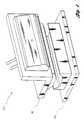
- FIG. 1is a perspective view of a mold drawn partially in phantom which may be used in carrying out the present invention
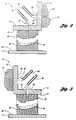
- FIG. 2is a cross-sectional view of the mold of FIG. 1 to depict a first foam injected in a first mold cavity of the mold;
- FIG. 3is a cross-sectional view of the mold to depict a second foam injected into a second mold cavity of the mold;
- FIG. 4is a flow chart of one method implemented in making a multiple foam substrate with the mold of FIG. 1 in accordance with the present invention
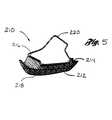
- FIG. 5is a cross-sectional view of a multiform substrate made by the method of FIG. 4;
- FIG. 6is a cross-sectional view of another multiple foam substrate formed with an airbag made by the method of FIG. 4;
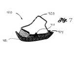
- FIG. 7is a cross-sectional view of yet another multiple foam substrate formed with a fastener by the method of FIG. 4 .
- FIG. 1illustrates a mold 10 drawn partially in phantom. Mold 10 may be used for manufacturing a multiple foam interior trim substrate in accordance with one embodiment of the present invention. As shown, mold 10 includes lower portion 12 and upper portion 14 (drawn in phantom).
- FIG. 2illustrates a cross-sectional side view of mold 10 in a first open position.
- upper portion 14includes first surface 16 from which first section 20 extends downwardly toward lower portion 12 .
- Upper portion 14further includes second surface 18 from which second section 22 extends.
- Second section 22includes extension 24 integrally extending from second section 22 .
- Lower portion 12includes lower surface 26 from which lower section 28 extends upwardly. From the open position, first section 20 is lowered to a first closed position and engages lower section 28 to define first mold cavity 32 .
- upper portion 14includes first injection hole 36 formed thereon through first surface 16 and first section 20 . Hole 36 is in fluid communication with first mold cavity at the first closed position. First injection hole 36 is formed to receive first nozzle 42 through which first foam 43 is injected into first mold cavity 32 .
- FIG. 3illustrates a cross-sectional side view of mold 10 in a second open position. From the second open position, second section 22 is lowered to a second closed position and engages lower section 28 to define second mold cavity 34 .
- Upper portion 14further includes second injection hole 38 formed thereon through second surface 18 and second section 22 . Hole 38 is in fluid communication with second mold cavity 34 in the second closed position, as shown in FIG. 3 . Second injection hole 38 is formed to receive second nozzle 44 through which second foam 45 is injected into second mold cavity 34 , as shown in FIG. 3 . As shown, upper portion 14 rotates approximately 90° such that second surface 18 faces downwardly toward lower surface 26 in order for second section 22 to engage with lower section 28 .
- Mold 10may include conventional controls, plumbing, and mold-actuating mechanisms to allow proper operation of lower portion 12 and upper portion 14 .
- portions 12 , 14 of mold 10may be mounted on tie-rods.
- lower portion 12is stationary, while upper portion 14 is movable to permit opening and closing of portions 12 and 14 .
- upper portion 14is configured to rotate providing pivotal movement such that second section 22 faces downwardly and may engage with lower section 28 .
- Actuations of portions 12 , 14may be by hydraulic, air cylinder, or manual.
- first and second foams 43 , 45are polyurethane foams having different properties.
- first foam 43is preferably a high density flexible urethane foam and second foam 45 is preferably a rigid structural foam.
- High density urethane foamis defined as foam having a density of a range between 80-125 kg/m 3 .
- Structural foamis defined as urethane foam having a density of a range between 40-150 kg/m 3 .
- the foamsmay respectively be supplied through their respective nozzles from separate conventional mixheads (not shown) which dispense a mixture of preferably isocyanate and polyol systems into the mold in the closed positions.
- the isocyanate and polyol systemsmay be stored in separate tanks, and metered to the respective mixhead. It is to be noted that other foams may be used which would not fall beyond the scope or spirit of the present invention. It is to be noted that the material comprising the foam, e.g., polyurethane, may be recycled material or virgin (non-recycled) material.
- FIG. 4illustrates one method 110 implemented to manufacture a multiple foam interior trim substrate with mold 10 of FIGS. 1-3.
- the methodincludes providing first foam 43 and second foam 45 of differing physical properties.
- first foam 43is a flexible polyurethane foam and second foam 45 is a rigid polyurethane foam.
- a difference in the densities between foams 43 , 45provides a difference in physical properties of the two foams.
- first foam 43has a density less than the density of second foam 45 .
- first foam 43may have a greater density than second foam 45 .
- mold 10 of FIGS. 1-3will have sections configured to form interior trim substrate 210 .
- first foam 43is injected into first mold cavity 32 , as shown in box 114 of FIG. 4 .
- First foam 43is injected into first mold cavity 32 through hole 36 by first nozzle 42 at a temperature between about 70° and 90° F. and at a high pressure of up to 3000 pounds per square inch gauge (psig).
- psigpounds per square inch gauge
- first mold cavity 32is filled with first foam 43 , and nozzle 42 is closed.
- First foam 43 in first mold cavity 32is stored for 2-3 minutes in order to cure to form a substantially non-mixing surface of a resulting part as shown in box 116 .
- the resulting partincreases in strength and stiffness enough to substantially prevent mixing of fist and second foams 43 , 45 when second foam 45 is injected thereon, as described below.
- upper portion 14 of mold 10disengages from stationary lower portion 12 by moving upwardly. Upper portion 14 then rotates about 90° in order for second surface 18 to face downwardly toward lower section 28 of lower surface 26 . Upper portion 14 then moves downwardly to engage second section 22 with lower section 28 .
- second nozzle 44injects second foam 45 into second mold cavity 34 onto the non-mixing surface of first foam 43 , as shown in box 118 .
- nozzle 44closes at a temperature between about 70° and 90° F. and at a high pressure of up to 3000 pounds per square inch gauge (psig).
- second foam 45is stored in second mold cavity 34 for 2-3 minutes in order to cure and bond with the non-mixing surface of first foam 43 to define the multiple foam substrate having the predetermined shape.
- the curing durationallows the substrate to build up enough strength and stiffness to be bonded with the non-mixing surface of the resulting part and to be removed from the mold when sufficient curing is complete.
- the substrateis post-cured for 1-2 days at approximately 70° F. to enhance physical properties and part stability.
- interior trim substrate 210includes high density urethane foam portion 212 and structural foam portion 214 integral therewith to define inner surface 216 and outer surface 218 .
- high density urethane foam portion 212may act as a soft aesthetic outer layer for a show surface of an A-pillar section of a vehicle compartment.
- Structural foam portion 214acts as an energy absorbing layer for collision impacts.
- Outer surface 218acts as a decorative cover or self-skinning surface having aesthetic features, eliminating the need of cloth disposed thereon. This may be accomplished by having portions 12 , 14 of mold 10 be in communication with one or a plurality of heating platens (not shown) in order to heat mold 10 during method 110 of the present invention.
- the heating platensmay be heated to a temperature ranging between 120° F. and 200° F. in order to heat mold 10 to a temperature between 120° F. and 150° F.
- the foam in contact with lower section 28is molded to the shape of either first mold cavity 32 or second mold cavity 34 .
- the molded foamtakes on a grain texture and firm surface.
- interior trim substrate 210has outer surface 218 with aesthetic features that do not require cloth or an outer layer to be placed thereon. If desired, additional cloth or outer layer may be attached thereto in order to provide a more aesthetic look.
- the decorative cover or outer layermay be placed in mold 10 prior to injecting foam in mold 10 , eliminating the need of attaching an outer layer after heating.
- the decorative covermay be applied by a cloth placed thereon, as mentioned above, or by a color spray sprayed onto mold 10 prior to injecting foam in mold 10 .
- Other ways of applying a decorative cover in the mold prior to injecting foam in the molddo not fall beyond the scope and spirit of this invention.
- FIG. 5depicts inner surface 216 flanking sheet metal structure 220 , it is to be noted that surface 216 may be configured adjacent only one side of structure 220 , as desired.
- substrate 310includes high density urethane foam 312 , structural foam 314 attached to foam 312 , and deployable airbag 316 also attached to foam 312 .
- Thismay be accomplished by loading deployable airbag 316 onto high density urethane foam 312 after storing first foam 43 in first mold cavity 32 and prior to injecting second foam 45 in second mold cavity 34 .
- second section 22is be formed without extension 24 to allow space for airbag 316 on foam 312 .
- airbag 316may be loaded onto foam 312 automatically, e.g., by robotics, or manually, e.g., by hand.
- high density urethane foam 312also includes notch 318 formed between airbag 316 and structural foam 314 in order to accommodate deployment of airbag 316 .
- notch 318provides a portion of high density urethane foam 312 adjacent airbag 316 to flex away from sheet metal structure 320 , allowing airbag 316 to deploy in the vehicle compartment.
- conventional fastener 413 or a plurality of fasteners 413may be disposed within the mold in order to be bonded to foams 412 , 414 to provide an interior trim substrate 410 having an integral fastener that may be directly attached to structure 420 of the vehicle. This eliminates the need of adhesives used to glue the fasteners onto the substrate.
Landscapes
- Engineering & Computer Science (AREA)
- Mechanical Engineering (AREA)
- Manufacturing & Machinery (AREA)
- Casting Or Compression Moulding Of Plastics Or The Like (AREA)
Abstract
Description
Claims (26)
Priority Applications (4)
| Application Number | Priority Date | Filing Date | Title |
|---|---|---|---|
| US09/561,002US6451233B1 (en) | 2000-04-28 | 2000-04-28 | Method of making a multiple foam interior trim substrate |
| DE10120267ADE10120267B4 (en) | 2000-04-28 | 2001-04-25 | Method for producing a multiple foam interior lining substrate |
| US10/245,194US6773795B2 (en) | 2000-04-28 | 2002-09-17 | Multiple foam energy absorbing substrate assembly |
| US10/245,731US6805542B2 (en) | 2000-04-28 | 2002-09-17 | Tool for forming a multiple foam substrate for impact energy absorption |
Applications Claiming Priority (1)
| Application Number | Priority Date | Filing Date | Title |
|---|---|---|---|
| US09/561,002US6451233B1 (en) | 2000-04-28 | 2000-04-28 | Method of making a multiple foam interior trim substrate |
Related Child Applications (2)
| Application Number | Title | Priority Date | Filing Date |
|---|---|---|---|
| US10/245,731DivisionUS6805542B2 (en) | 2000-04-28 | 2002-09-17 | Tool for forming a multiple foam substrate for impact energy absorption |
| US10/245,194DivisionUS6773795B2 (en) | 2000-04-28 | 2002-09-17 | Multiple foam energy absorbing substrate assembly |
Publications (1)
| Publication Number | Publication Date |
|---|---|
| US6451233B1true US6451233B1 (en) | 2002-09-17 |
Family
ID=24240248
Family Applications (3)
| Application Number | Title | Priority Date | Filing Date |
|---|---|---|---|
| US09/561,002Expired - Fee RelatedUS6451233B1 (en) | 2000-04-28 | 2000-04-28 | Method of making a multiple foam interior trim substrate |
| US10/245,194Expired - Fee RelatedUS6773795B2 (en) | 2000-04-28 | 2002-09-17 | Multiple foam energy absorbing substrate assembly |
| US10/245,731Expired - Fee RelatedUS6805542B2 (en) | 2000-04-28 | 2002-09-17 | Tool for forming a multiple foam substrate for impact energy absorption |
Family Applications After (2)
| Application Number | Title | Priority Date | Filing Date |
|---|---|---|---|
| US10/245,194Expired - Fee RelatedUS6773795B2 (en) | 2000-04-28 | 2002-09-17 | Multiple foam energy absorbing substrate assembly |
| US10/245,731Expired - Fee RelatedUS6805542B2 (en) | 2000-04-28 | 2002-09-17 | Tool for forming a multiple foam substrate for impact energy absorption |
Country Status (2)
| Country | Link |
|---|---|
| US (3) | US6451233B1 (en) |
| DE (1) | DE10120267B4 (en) |
Cited By (11)
| Publication number | Priority date | Publication date | Assignee | Title |
|---|---|---|---|---|
| US20040174049A1 (en)* | 2003-03-04 | 2004-09-09 | Byma George B. | Acoustically attenuating headliner and method for making same |
| US20040178660A1 (en)* | 2003-02-19 | 2004-09-16 | Dry Alan G. | Method of forming a vehicle component |
| US20050090573A1 (en)* | 2003-10-22 | 2005-04-28 | Milliren Charles M. | Viscoelastic foam layer and composition |
| US20050255306A1 (en)* | 2002-03-15 | 2005-11-17 | Martin Wolff | Panel element, particularly for a motor vehicle, and method for the production thereof |
| US20060226574A1 (en)* | 2003-08-25 | 2006-10-12 | Bozio Ronald A | Trim panel |
| US20070020420A1 (en)* | 2005-07-21 | 2007-01-25 | Huffel Patrick V | Vehicle glove box and method of fabricating the same |
| US20100007122A1 (en)* | 2008-07-14 | 2010-01-14 | Lear Corporation | Automotive seat foam pad assembly |
| US20100025970A1 (en)* | 2008-07-29 | 2010-02-04 | Lear Corporation | Automotive seat trim cover |
| US20130302584A1 (en)* | 2011-01-14 | 2013-11-14 | Daniel J. LaFlamme | Foam Assembly And Method Of Making The Same |
| US20200010043A1 (en)* | 2017-03-23 | 2020-01-09 | Bayerische Motoren Werke Aktiengesellschaft | Lining Element, and Process for Manufacturing a Lining Element |
| CN114683464A (en)* | 2020-12-31 | 2022-07-01 | 青岛海尔电冰箱有限公司 | Foam base for electrical appliance packaging, mold for making the same, and method for making the same |
Families Citing this family (18)
| Publication number | Priority date | Publication date | Assignee | Title |
|---|---|---|---|---|
| US20060068193A1 (en)* | 2004-09-29 | 2006-03-30 | Lear Corporation | Method and apparatus for making a trim panel with a self-skinning blown elastomer component |
| US7458631B2 (en) | 2004-10-19 | 2008-12-02 | International Automotive Components Group North America, Inc. | Automotive armrest with soft feel and method of making the same |
| US7478854B2 (en) | 2004-10-19 | 2009-01-20 | International Automotive Components Group North America, Inc. | Automotive handle with soft feel and method of making the same |
| US7458604B2 (en) | 2004-10-20 | 2008-12-02 | International Automotive Components Group North America, Inc. | Automotive trim assembly having an integrated airbag door |
| DE102004054646B4 (en)* | 2004-11-11 | 2008-12-04 | Carcoustics Tech Center Gmbh | Lightweight sound-insulating panel for a body part of a motor vehicle and method for its production |
| US7234726B2 (en)* | 2004-12-16 | 2007-06-26 | Visteon Global Technologies, Inc. | Airbag assembly for improving force distribution |
| US20070082099A1 (en)* | 2005-10-11 | 2007-04-12 | Dieter Kellerstrass | Thermal food transport containers and methods of manufacturing the same |
| US7556492B2 (en)* | 2005-11-09 | 2009-07-07 | Nike, Inc. | Footwear mold heating system and method |
| DE102006009134B4 (en)* | 2006-02-24 | 2016-03-24 | Bayer Materialscience Aktiengesellschaft | Improved process for producing a lightweight, soundproofing panel for automobiles and related trim |
| US20100038810A1 (en)* | 2009-04-21 | 2010-02-18 | Wen-Kuo Tsai | Method for making a foamed sole |
| DE102012007876B4 (en) | 2012-04-19 | 2018-03-08 | Ulrich Krämer | Combination tool for PUR |
| HUP1200268A2 (en)* | 2012-05-08 | 2013-11-28 | Ratipur Gepjarmuealkatreszt Es Autofelszerelest Gyarto Es Ertekesitoe Kft | Method for manufacturing pur integral foam with modified structure, pur integral foam with modified structure |
| DE102012022249B4 (en)* | 2012-08-13 | 2021-03-04 | Shanghai Yanfeng Jinqiao Automotive Trim Systems Co., Ltd. | Vehicle interior trim part and method for connecting a carrier and a connection element |
| DE102016222328A1 (en)* | 2016-11-14 | 2018-05-17 | Volkswagen Aktiengesellschaft | Method for producing a sound-absorbing component, in particular a trim part, for a motor vehicle, and sound-insulating component |
| FR3082137B1 (en)* | 2018-06-12 | 2023-11-24 | Faurecia Automotive Ind | METHOD FOR MANUFACTURING A PART OF EQUIPMENT OF A MOTOR VEHICLE, PART OF EQUIPMENT AND ASSOCIATED ASSEMBLY METHOD |
| US11780129B2 (en) | 2020-03-20 | 2023-10-10 | King Steel Machinery Co., Ltd. | Molding method for operating molding device |
| US12049032B2 (en) | 2020-03-20 | 2024-07-30 | King Steel Machinery Co., Ltd. | Injection molding method |
| CN113547611B (en)* | 2021-07-05 | 2023-04-07 | 湖南科技大学 | Processing method and manufacturing device for integrally forming large ceramic wine jar |
Citations (34)
| Publication number | Priority date | Publication date | Assignee | Title |
|---|---|---|---|---|
| US3534129A (en)* | 1967-04-06 | 1970-10-13 | Elastomer Ag | Seat construction and the like |
| US4246213A (en) | 1978-08-02 | 1981-01-20 | Nissan Motor Company, Limited | Method of producing a cover member for a safety air-cushion |
| US4327937A (en) | 1978-11-09 | 1982-05-04 | Daimler-Benz Aktiengesellschaft | Downwardly foldable covering for a gas cushion |
| US4714575A (en)* | 1986-05-27 | 1987-12-22 | Ex-Cell-O Corporation | Method for manufacturing RIM composites |
| US4893833A (en) | 1988-09-08 | 1990-01-16 | Tip Engineering Group, Inc. | Closure for an air bag deployment opening |
| US4923653A (en)* | 1988-03-30 | 1990-05-08 | Ikeda Bussan Co., Ltd. | Method of molding skin-covered foamed plastic article |
| US4975229A (en)* | 1985-04-16 | 1990-12-04 | Honda Giken Kogyo Kabushiki Kaisha | Process for producing laminated resin foam |
| US5043114A (en)* | 1987-11-04 | 1991-08-27 | Honda Giken Kogyo Kabushiki Kaisha | Molding method for manufacturing expansion-molded insert-embedded resin product |
| US5072967A (en)* | 1990-07-12 | 1991-12-17 | Davidson Textron Inc. | Instrument panel with invisible airbag deployment door |
| US5082310A (en) | 1989-11-06 | 1992-01-21 | Tip Engineering Group, Inc. | Arrangement for providing an air bag deployment opening |
| US5176860A (en)* | 1988-07-11 | 1993-01-05 | Atoma International Of America, Inc. | Method of the manufacture of an upholstery element |
| US5224732A (en) | 1991-07-16 | 1993-07-06 | Toyota Motor Co Ltd | Inflatable restraint system for side impact crash protection |
| US5273309A (en) | 1992-06-19 | 1993-12-28 | General Motors Corporation | Air bag for side impact |
| US5308112A (en) | 1993-04-21 | 1994-05-03 | General Motors Corporation | Unfurled side impact air bag |
| US5382051A (en) | 1991-08-28 | 1995-01-17 | Concept Analysis Corporation | Pneumatic pads for the interior of vehicles |
| US5498030A (en) | 1995-03-28 | 1996-03-12 | General Motors Corporation | Air bag module |
| US5503427A (en) | 1995-03-30 | 1996-04-02 | Morton International, Inc. | Energy absorption cover for passenger-side airbag module |
| US5547214A (en) | 1995-01-23 | 1996-08-20 | Alliedsignal Inc. | Side impact soft pack air bag module |
| US5601332A (en) | 1995-01-30 | 1997-02-11 | Hoover Universal, Inc. | Replaceable seat booster with an inflatable air cushion module |
| US5803490A (en) | 1997-05-05 | 1998-09-08 | Chrysler Corporation | Side air bag |
| US5826938A (en) | 1995-10-11 | 1998-10-27 | Araco Kabushiki Kaisha | Vehicle seat with side air bag assembly |
| US5829778A (en) | 1997-07-31 | 1998-11-03 | General Motors Corporation | Air bag restraint system |
| US5837172A (en)* | 1995-10-30 | 1998-11-17 | Davidson Textron Inc. | Method for manufacturing an automotive trim product |
| US5839752A (en) | 1995-09-22 | 1998-11-24 | Toyoda Gosei Co., Ltd. | Air bag cover and manufacturing method thereof |
| US5845929A (en) | 1994-05-21 | 1998-12-08 | Petri Ag | Covering means for air-bag-collision-safety means as well as process for the production thereof |
| US5860673A (en) | 1995-09-18 | 1999-01-19 | Toyota Jidosha Kabushiki Kaisha | Seat structure having a side impact air bag apparatus |
| US5863064A (en) | 1997-08-14 | 1999-01-26 | Textron Autmotive Company Inc. | Skin for automotive air bag cover panel formed by casting different plastic materials |
| US5865461A (en) | 1995-06-16 | 1999-02-02 | Toyoda Gosei Co., Ltd. | Interior finish member for an automobile with an air bag device and manufacturing method thereof |
| US5871229A (en) | 1996-06-10 | 1999-02-16 | Kansei Corporation | Automobile airbag device |
| US5927749A (en) | 1996-11-12 | 1999-07-27 | Magna Lomason Corporation | Side air bag directional guide system |
| US5941557A (en) | 1997-08-08 | 1999-08-24 | General Motors Corporation | Air bag cover door with tether |
| US5967546A (en) | 1996-11-12 | 1999-10-19 | Magna Lomason Corporation | Side air bag directional guide system |
| US5989699A (en)* | 1997-12-01 | 1999-11-23 | Woodbridge Foam Corporation | Foam composite material comprising a first foam having an uncontoured surface, and a second, different foam fixed to the first foam at its uncontoured surface |
| US6045732A (en)* | 1994-11-10 | 2000-04-04 | Sumitomo Chemical Company, Limited | Method for producing a multi-layer molded article |
Family Cites Families (9)
| Publication number | Priority date | Publication date | Assignee | Title |
|---|---|---|---|---|
| US3302243A (en)* | 1964-04-16 | 1967-02-07 | Herbert P Ludwig | Apparatus for the injection molding of plastic articles especially shoes |
| DE1529890A1 (en)* | 1966-11-19 | 1969-10-30 | Desma Werke Gmbh | Method and device for producing multi-part soles with such a sole |
| NL153475B (en)* | 1966-12-23 | 1977-06-15 | Nl Schoen En Lederfabrieken Ba | PROCESS FOR THE MANUFACTURE OF FOOTWEAR, AS WELL AS FOOTWEAR OBTAINED UNDER THE APPLICATION OF THIS PROCESS. |
| US3671621A (en)* | 1970-07-01 | 1972-06-20 | Tatsuo Fukuoka | Injection molding method for sandals |
| US4389358A (en)* | 1981-06-22 | 1983-06-21 | Kmmco Structural Foam, Inc. | Method and apparatus for making an integral structural cellular and non-cellular plastic or resinous article with a smooth outer surface |
| IT8422307V0 (en)* | 1984-06-15 | 1984-06-15 | Devi Spa | MACHINE FOR THE PRODUCTION OF PRINTED ITEMS IN PLASTIC MATERIAL, IN PARTICULAR OF HELMETS FOR MOTORCYCLISTS AND SIMILAR. |
| DE4480340T1 (en)* | 1993-12-29 | 1996-12-19 | Kobe Steel Ltd | Two-layer foam injection molding machine |
| US5695699A (en)* | 1994-09-21 | 1997-12-09 | Taisei Plas Co., Ltd. | Heterogenous foam injection molding method |
| US5741025A (en)* | 1996-05-22 | 1998-04-21 | Ks Centoco Ltd. | Integral steering wheel and air bag assembly |
- 2000
- 2000-04-28USUS09/561,002patent/US6451233B1/ennot_activeExpired - Fee Related
- 2001
- 2001-04-25DEDE10120267Apatent/DE10120267B4/ennot_activeExpired - Fee Related
- 2002
- 2002-09-17USUS10/245,194patent/US6773795B2/ennot_activeExpired - Fee Related
- 2002-09-17USUS10/245,731patent/US6805542B2/ennot_activeExpired - Fee Related
Patent Citations (34)
| Publication number | Priority date | Publication date | Assignee | Title |
|---|---|---|---|---|
| US3534129A (en)* | 1967-04-06 | 1970-10-13 | Elastomer Ag | Seat construction and the like |
| US4246213A (en) | 1978-08-02 | 1981-01-20 | Nissan Motor Company, Limited | Method of producing a cover member for a safety air-cushion |
| US4327937A (en) | 1978-11-09 | 1982-05-04 | Daimler-Benz Aktiengesellschaft | Downwardly foldable covering for a gas cushion |
| US4975229A (en)* | 1985-04-16 | 1990-12-04 | Honda Giken Kogyo Kabushiki Kaisha | Process for producing laminated resin foam |
| US4714575A (en)* | 1986-05-27 | 1987-12-22 | Ex-Cell-O Corporation | Method for manufacturing RIM composites |
| US5043114A (en)* | 1987-11-04 | 1991-08-27 | Honda Giken Kogyo Kabushiki Kaisha | Molding method for manufacturing expansion-molded insert-embedded resin product |
| US4923653A (en)* | 1988-03-30 | 1990-05-08 | Ikeda Bussan Co., Ltd. | Method of molding skin-covered foamed plastic article |
| US5176860A (en)* | 1988-07-11 | 1993-01-05 | Atoma International Of America, Inc. | Method of the manufacture of an upholstery element |
| US4893833A (en) | 1988-09-08 | 1990-01-16 | Tip Engineering Group, Inc. | Closure for an air bag deployment opening |
| US5082310A (en) | 1989-11-06 | 1992-01-21 | Tip Engineering Group, Inc. | Arrangement for providing an air bag deployment opening |
| US5072967A (en)* | 1990-07-12 | 1991-12-17 | Davidson Textron Inc. | Instrument panel with invisible airbag deployment door |
| US5224732A (en) | 1991-07-16 | 1993-07-06 | Toyota Motor Co Ltd | Inflatable restraint system for side impact crash protection |
| US5382051A (en) | 1991-08-28 | 1995-01-17 | Concept Analysis Corporation | Pneumatic pads for the interior of vehicles |
| US5273309A (en) | 1992-06-19 | 1993-12-28 | General Motors Corporation | Air bag for side impact |
| US5308112A (en) | 1993-04-21 | 1994-05-03 | General Motors Corporation | Unfurled side impact air bag |
| US5845929A (en) | 1994-05-21 | 1998-12-08 | Petri Ag | Covering means for air-bag-collision-safety means as well as process for the production thereof |
| US6045732A (en)* | 1994-11-10 | 2000-04-04 | Sumitomo Chemical Company, Limited | Method for producing a multi-layer molded article |
| US5547214A (en) | 1995-01-23 | 1996-08-20 | Alliedsignal Inc. | Side impact soft pack air bag module |
| US5601332A (en) | 1995-01-30 | 1997-02-11 | Hoover Universal, Inc. | Replaceable seat booster with an inflatable air cushion module |
| US5498030A (en) | 1995-03-28 | 1996-03-12 | General Motors Corporation | Air bag module |
| US5503427A (en) | 1995-03-30 | 1996-04-02 | Morton International, Inc. | Energy absorption cover for passenger-side airbag module |
| US5865461A (en) | 1995-06-16 | 1999-02-02 | Toyoda Gosei Co., Ltd. | Interior finish member for an automobile with an air bag device and manufacturing method thereof |
| US5860673A (en) | 1995-09-18 | 1999-01-19 | Toyota Jidosha Kabushiki Kaisha | Seat structure having a side impact air bag apparatus |
| US5839752A (en) | 1995-09-22 | 1998-11-24 | Toyoda Gosei Co., Ltd. | Air bag cover and manufacturing method thereof |
| US5826938A (en) | 1995-10-11 | 1998-10-27 | Araco Kabushiki Kaisha | Vehicle seat with side air bag assembly |
| US5837172A (en)* | 1995-10-30 | 1998-11-17 | Davidson Textron Inc. | Method for manufacturing an automotive trim product |
| US5871229A (en) | 1996-06-10 | 1999-02-16 | Kansei Corporation | Automobile airbag device |
| US5927749A (en) | 1996-11-12 | 1999-07-27 | Magna Lomason Corporation | Side air bag directional guide system |
| US5967546A (en) | 1996-11-12 | 1999-10-19 | Magna Lomason Corporation | Side air bag directional guide system |
| US5803490A (en) | 1997-05-05 | 1998-09-08 | Chrysler Corporation | Side air bag |
| US5829778A (en) | 1997-07-31 | 1998-11-03 | General Motors Corporation | Air bag restraint system |
| US5941557A (en) | 1997-08-08 | 1999-08-24 | General Motors Corporation | Air bag cover door with tether |
| US5863064A (en) | 1997-08-14 | 1999-01-26 | Textron Autmotive Company Inc. | Skin for automotive air bag cover panel formed by casting different plastic materials |
| US5989699A (en)* | 1997-12-01 | 1999-11-23 | Woodbridge Foam Corporation | Foam composite material comprising a first foam having an uncontoured surface, and a second, different foam fixed to the first foam at its uncontoured surface |
Cited By (21)
| Publication number | Priority date | Publication date | Assignee | Title |
|---|---|---|---|---|
| US7361293B2 (en) | 2002-03-15 | 2008-04-22 | Johnson Controls Gmbh | Panel element, particularly for a motor vehicle, and method for the production thereof |
| US20050255306A1 (en)* | 2002-03-15 | 2005-11-17 | Martin Wolff | Panel element, particularly for a motor vehicle, and method for the production thereof |
| US6899363B2 (en)* | 2003-02-19 | 2005-05-31 | Lear Corporation | Method of forming a vehicle component |
| US20040178660A1 (en)* | 2003-02-19 | 2004-09-16 | Dry Alan G. | Method of forming a vehicle component |
| US20040174049A1 (en)* | 2003-03-04 | 2004-09-09 | Byma George B. | Acoustically attenuating headliner and method for making same |
| US6951264B2 (en) | 2003-03-04 | 2005-10-04 | Lear Corporation | Acoustically attenuating headliner and method for making same |
| US20060226574A1 (en)* | 2003-08-25 | 2006-10-12 | Bozio Ronald A | Trim panel |
| US20050090573A1 (en)* | 2003-10-22 | 2005-04-28 | Milliren Charles M. | Viscoelastic foam layer and composition |
| US7078443B2 (en) | 2003-10-22 | 2006-07-18 | Intellectual Property Holdings, Llc | Viscoelastic foam layer and composition |
| US20070021519A1 (en)* | 2003-10-22 | 2007-01-25 | Milliren Charles M | Viscoelastic foam layer and composition |
| US8975306B2 (en) | 2003-10-22 | 2015-03-10 | Intellectual Property Holdings, Llc | Viscoelastic foam layer and composition |
| US20070020420A1 (en)* | 2005-07-21 | 2007-01-25 | Huffel Patrick V | Vehicle glove box and method of fabricating the same |
| US20100007122A1 (en)* | 2008-07-14 | 2010-01-14 | Lear Corporation | Automotive seat foam pad assembly |
| US9120411B2 (en) | 2008-07-14 | 2015-09-01 | Lear Corporation | Automotive seat foam pad assembly |
| US8113539B2 (en) | 2008-07-29 | 2012-02-14 | Lear Corporation | Automotive seat trim cover |
| US20100025970A1 (en)* | 2008-07-29 | 2010-02-04 | Lear Corporation | Automotive seat trim cover |
| US20130302584A1 (en)* | 2011-01-14 | 2013-11-14 | Daniel J. LaFlamme | Foam Assembly And Method Of Making The Same |
| US20200010043A1 (en)* | 2017-03-23 | 2020-01-09 | Bayerische Motoren Werke Aktiengesellschaft | Lining Element, and Process for Manufacturing a Lining Element |
| US11891010B2 (en)* | 2017-03-23 | 2024-02-06 | Bayerische Motoren Werke Aktiengesellschaft | Lining element, and process for manufacturing a lining element |
| CN114683464A (en)* | 2020-12-31 | 2022-07-01 | 青岛海尔电冰箱有限公司 | Foam base for electrical appliance packaging, mold for making the same, and method for making the same |
| CN114683464B (en)* | 2020-12-31 | 2023-11-14 | 青岛海尔电冰箱有限公司 | Foam base for electrical appliance packaging, mold for making the same and method for making the same |
Also Published As
| Publication number | Publication date |
|---|---|
| DE10120267B4 (en) | 2006-02-09 |
| US20030017224A1 (en) | 2003-01-23 |
| US20030017323A1 (en) | 2003-01-23 |
| DE10120267A1 (en) | 2001-12-20 |
| US6805542B2 (en) | 2004-10-19 |
| US6773795B2 (en) | 2004-08-10 |
Similar Documents
| Publication | Publication Date | Title |
|---|---|---|
| US6451233B1 (en) | Method of making a multiple foam interior trim substrate | |
| EP0639440B1 (en) | Method of constructing a molded composite article comprising a foam backing | |
| US5700050A (en) | Blow molded structural interior automotive parts | |
| US5590901A (en) | Method and apparatus for vehicle trim panel having hidden air bag door | |
| EP0963283B2 (en) | Process for making decorative automotive interior trim articles with integral light stable polyurethane elastomer covering | |
| US6379595B1 (en) | Multiple density interior trim substrate and method of making same | |
| US5549324A (en) | Construction and method of forming a door assembly for an air system | |
| JP4953420B2 (en) | Molded product and insert molding method | |
| US20040126532A1 (en) | Trim articles with light stable covering containing invisible tear seam, and process of making the same | |
| EP2039489A1 (en) | Process for the production of a foamed article. | |
| EP1101588A2 (en) | Foam composite material and process for production thereof | |
| WO1999008904A1 (en) | Skin for automotive air bag cover panel formed by casting different plastic materials | |
| US7033660B2 (en) | Method of making an interior trim panel for a door and an article made thereby | |
| US7147808B2 (en) | Vehicle part with integrated impact management feature and method of making same | |
| EP1975005B1 (en) | Interior trim component and method of forming the same | |
| JP2000351351A (en) | Skin integral interior automotive trim part and manufacture thereof | |
| JP2003220854A (en) | Interior decoration member for vehicle | |
| US20040000737A1 (en) | Method of manufacturing energy absorbent vehicle components | |
| US20060082179A1 (en) | Automotive trim assembly having impact countermeasures and method of making the same | |
| KR101145140B1 (en) | Manufacturing method of Crash pad for vehicle | |
| US11478961B2 (en) | Process for obtaining thermo-structural composites | |
| US20060006568A1 (en) | Method of making a grab handle | |
| JP2002307470A (en) | Method for producing interior decoration article for car | |
| CA2174557A1 (en) | Blow molded structural interior automotive parts | |
| MXPA99007059A (en) | Process for making decorative automotive interior trim articles with integral light stable polyurethane elastomer covering |
Legal Events
| Date | Code | Title | Description |
|---|---|---|---|
| AS | Assignment | Owner name:LEAR CORPORATION, MICHIGAN Free format text:ASSIGNMENT OF ASSIGNORS INTEREST;ASSIGNORS:BYMA, GEORGE B.;CRISTEA, BRIAN A.;MUHLBACHER, RICHARD;REEL/FRAME:011172/0842;SIGNING DATES FROM 20000822 TO 20001002 | |
| FPAY | Fee payment | Year of fee payment:4 | |
| AS | Assignment | Owner name:JPMORGAN CHASE BANK, N.A., AS GENERAL ADMINISTRATI Free format text:SECURITY AGREEMENT;ASSIGNOR:LEAR CORPORATION;REEL/FRAME:017858/0719 Effective date:20060425 | |
| AS | Assignment | Owner name:INTERNATIONAL AUTOMOTIVE COMPONENTS GROUP NORTH AM Free format text:ASSIGNMENT OF ASSIGNORS INTEREST;ASSIGNOR:LEAR CORPORATION;REEL/FRAME:019215/0727 Effective date:20070427 | |
| REMI | Maintenance fee reminder mailed | ||
| LAPS | Lapse for failure to pay maintenance fees | ||
| STCH | Information on status: patent discontinuation | Free format text:PATENT EXPIRED DUE TO NONPAYMENT OF MAINTENANCE FEES UNDER 37 CFR 1.362 | |
| FP | Lapsed due to failure to pay maintenance fee | Effective date:20100917 | |
| AS | Assignment | Owner name:LEAR CORPORATION, MICHIGAN Free format text:RELEASE BY SECURED PARTY;ASSIGNOR:JPMORGAN CHASE BANK, N.A.;REEL/FRAME:032722/0553 Effective date:20100830 | |
| AS | Assignment | Owner name:LEAR CORPORATION, MICHIGAN Free format text:RELEASE BY SECURED PARTY;ASSIGNOR:JPMORGAN CHASE BANK, N.A., AS AGENT;REEL/FRAME:037731/0918 Effective date:20160104 |