US6450467B2 - Tilt adjustable keyboard support - Google Patents
Tilt adjustable keyboard supportDownload PDFInfo
- Publication number
- US6450467B2 US6450467B2US09/902,430US90243001AUS6450467B2US 6450467 B2US6450467 B2US 6450467B2US 90243001 AUS90243001 AUS 90243001AUS 6450467 B2US6450467 B2US 6450467B2
- Authority
- US
- United States
- Prior art keywords
- keyboard
- workstation
- ball bearing
- engaging member
- respect
- Prior art date
- Legal status (The legal status is an assumption and is not a legal conclusion. Google has not performed a legal analysis and makes no representation as to the accuracy of the status listed.)
- Expired - Lifetime
Links
- 238000003491arrayMethods0.000claimsdescription13
- 238000005096rolling processMethods0.000claims4
- 230000000750progressive effectEffects0.000description6
- 230000036316preloadEffects0.000description5
- 230000003993interactionEffects0.000description3
- 230000007246mechanismEffects0.000description3
- 230000008859changeEffects0.000description2
- 230000007423decreaseEffects0.000description2
- 230000003247decreasing effectEffects0.000description2
- 239000002184metalSubstances0.000description2
- 239000004677NylonSubstances0.000description1
- 230000004075alterationEffects0.000description1
- 238000005452bendingMethods0.000description1
- 238000013479data entryMethods0.000description1
- 230000006872improvementEffects0.000description1
- 230000004048modificationEffects0.000description1
- 238000012986modificationMethods0.000description1
- 229920001778nylonPolymers0.000description1
- 238000003825pressingMethods0.000description1
Images


Classifications
- A—HUMAN NECESSITIES
- A47—FURNITURE; DOMESTIC ARTICLES OR APPLIANCES; COFFEE MILLS; SPICE MILLS; SUCTION CLEANERS IN GENERAL
- A47B—TABLES; DESKS; OFFICE FURNITURE; CABINETS; DRAWERS; GENERAL DETAILS OF FURNITURE
- A47B21/00—Tables or desks for office equipment, e.g. typewriters, keyboards
- A47B21/03—Tables or desks for office equipment, e.g. typewriters, keyboards with substantially horizontally extensible or adjustable parts other than drawers, e.g. leaves
- A47B21/0314—Platforms for supporting office equipment
- A47B2021/0321—Keyboard supports
- A47B2021/0335—Keyboard supports mounted under the worksurface
- A47B2021/0342—Keyboard supports mounted under the worksurface having one double articulated arm
- Y—GENERAL TAGGING OF NEW TECHNOLOGICAL DEVELOPMENTS; GENERAL TAGGING OF CROSS-SECTIONAL TECHNOLOGIES SPANNING OVER SEVERAL SECTIONS OF THE IPC; TECHNICAL SUBJECTS COVERED BY FORMER USPC CROSS-REFERENCE ART COLLECTIONS [XRACs] AND DIGESTS
- Y10—TECHNICAL SUBJECTS COVERED BY FORMER USPC
- Y10S—TECHNICAL SUBJECTS COVERED BY FORMER USPC CROSS-REFERENCE ART COLLECTIONS [XRACs] AND DIGESTS
- Y10S248/00—Supports
- Y10S248/917—Video display screen support
- Y10S248/918—Ancillary device support associated with a video display screen
Definitions
- the present inventionconcerns a keyboard support for orienting a keyboard such as a computer keyboard with respect to a workstation surface.
- keyboard supportsare sold by Workrite Ergonomics Accessories Inc., assignee of the present invention.
- One such keyboard supportis movably supported by a track that allows the keyboard to be retracted out from under a user's desk and then stored beneath the desk when the keyboard is not in use.
- This keyboard supportalso allows the user to adjust both the angle and the height of the keyboard in relation to its user.
- the tilt angles of the keyboardcan be adjusted through a continuously variable angle of a total of 25 degrees from a negative tilt (front of keyboard elevated with respect to its back) of 15 degrees to a positive tilt (front of keyboard lower than its back) of 10 degrees.
- This commercially available keyboardis sold by Workrite under the model designation numbers 170, 171, 173, and 175.
- Waterloo Furniture Componentspresently sells a support mechanism that includes a moveable linkage that couples a keyboard support to a desk.
- the keyboard supportrides in a track support on progressive ball bearing slides that are oriented vertically, such that the ball bearings are disposed within planes generally perpendicular to the desk.
- a tab that extends from the track support housingis pressed by the user to retract and store the keyboard support.
- the height of the keyboard supportis adjusted by rotating the keyboard support up and moving the keyboard support to the desired height and then releasing the keyboard support.
- the height of the keyboard supportis maintained by a braking system made up of two wedge shaped blocks and two bolt holding the blocks within an inclined slot.
- the Waterloo linkagealso includes a mechanism that allows a tilt angle to be varied over a range of about 6 degrees by loosening and then re-tightening a self locking nut.
- a pincan be repositioned within a limited extent slot in a member that forms part of the linkage. This adjustment is made when the keyboard support is being fabricated and is not adjustable by the keyboard user.
- One exemplary embodiment of the present inventionconcerns a keyboard support that allows a keyboard (typically a computer keyboard) to be moved and reoriented with respect to a workstation.
- a keyboardtypically a computer keyboard
- a keyboard supporting memberhas a generally planar keyboard support surface whose orientation is adjustable.
- a second, workstation engaging memberallows the user to move the keyboard back and forth with respect to the workstation.
- the movement of the keyboard within the workstation engaging membermay be accomplished on nylon slides or other suitable bearings.
- progressive ball bearing slides oriented horizontallysuch that the ball bearings are disposed in a plane generally parallel to the workstation are located in the workstation engaging member to allow the user to move the keyboard to a storage position and then move the keyboard to an in use position.
- This horizontal orientation of the ball bearing slidesprovides a workstation engaging member having a lower profile than prior art devices.
- a latch mechanismprevents movement of the keyboard back to the storage position after the keyboard in extended to the in use position unless a lever is pressed.
- a linkageinterconnects the two members for adjusting a relative position of the keyboard supporting member with respect to the workstation engaging member thereby allowing the keyboard position and orientation to be controlled by the user.
- the linkageincludes a bracket having one end rotatably connected to the workstation engaging member.
- the bracketextends away from the workstation engaging member at an angle that controls the height of the keyboard in relation to the work surface.
- the bracketdefines a pair of arcuate slots at one end spaced from the end that is connected to the workstation engaging member.
- the keyboard engaging memberdefines a pair of fingers each having an arcuate slot located at either side of the planar support surface.
- a connectorpasses through the arcuate slots of the bracket, the arcuate slots of the keyboard engaging member, a preload spring, and two wedge shaped pressure applying blocks.
- the pressure applying blocksexert an inward force on the fingers of the keyboard engaging member which in turn are frictionally engaged with the bracket.
- the preload springmaintains engagement between the blocks and the arcuate slots.
- the connectoris used for increasing and decreasing a frictional engagement between the pressure applying blocks, the bracket and the keyboard engaging member.
- the wedge shaped pressure applying blocksare urged along an incline in the fingers of the keyboard engaging member and the user is able to adjust an orientation between the keyboard engaging member and the workstation over a continuous range of values.
- tilt angles over a range of 25 degreescan be chosen.
- the keyboard engaging membermay be manually rotated in a direction which releases the frictional engagement between the pressure applying blocks and the keyboard engaging member's inclined finger segments allowing free movement of the bracket relative to the workstation engaging member and the user may adjust the height of the keyboard engaging member relative to the workstation.
- the pressure applying blocksmove back their original position prior to the manual rotation of the bracket thereby preserving the user's preferred orientation.
- FIG. 1is a perspective view of a keyboard support constructed in accordance with an exemplary embodiment of the present invention
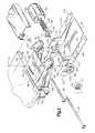
- FIG. 2is an exploded perspective view of the keyboard support depicted in FIG. 1;
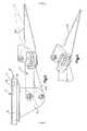
- FIG. 3is an elevation view of the keyboard support of FIGS. 1 and 2;
- FIG. 4is second segmented elevation view of the keyboard support wherein the keyboard contacting portion of the support has been rotated to a different orientation
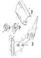
- FIG. 5is a bottom plan view, partially in section of the keyboard support depicted in FIGS. 1 and 2;
- FIG. 6is an elevation view of the keyboard support wherein the user has lowered the height of the keyboard with respect to a work surface but maintained an orientation with respect to the horizontal the same as the depiction in FIG. 4;
- FIGS. 7 and 8are perspective views of two pressure applying blocks used with an exemplary embodiment of the present invention.
- FIG. 9is a perspective view of a linkage cover assembly
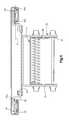
- FIG. 10is an enlarged side view of a workstation engaging member having a linear progressive ball bearing slide in a horizontal orientation shown in phantom line;
- FIG. 11is a front view of the workstation engaging member shown in FIG. 10;
- FIG. 12is a top plan view of a track for the progressive linear ball bearing slide
- FIG. 13is a top plan view of a ball bearing retainer
- FIG. 14is a viewe of the retainer as seen from the plane 14 — 14 in FIG. 13 .
- FIG. 1depicts a keyboard support 10 constructed in accordance with one exemplary embodiment of the invention.
- the support 10is intended to position a keyboard 12 with respect to a workstation such as a desk 14 .
- a keyboard engaging member 20has two spaced apart, generally planar keyboard support surfaces 22 a , 22 b that define a keyboard orientation relative to the desk 14 .
- a workstation engaging member 30 in the form of an elongated metal housinghas a top planar surface 31 that attaches to an undersurface of the desk 14 and supports the keyboard 12 for back and forth movement with respect to the desk 14 .
- the workstation engaging member 30attaches to a flat undersurface 14 a of the desk 14 by means of a plurality of fasteners (not shown).
- a linkage 40interconnects the keyboard engaging member 20 and a carriage 32 (see FIG. 3) and adjusts a relative height and orientation of the keyboard 12 with respect to the desk 14 .
- the orientationis continuously adjustable over a range of about 25 degrees and, for example, two different orientations of the keyboard 12 are depicted in FIGS. 3 and 4.
- the keyboard engaging member 20orients the keyboard generally horizontal with respect to the top surface 31 of the housing 30 that engages the desk 14 and in FIG. 4 the keyboard has a negative tilt.
- the keyboard 12When an operator is seated at the desk 14 , the keyboard 12 is moved out from under the desk to an in use position in front of the desk.
- the back and fourth movement of the keyboardis provided by progressive ball bearing slides 39 having bearings that movably support a carriage bracket 37 connected to the carriage 32 (FIGS. 10 and 11) for movement along a generally linear travel path within tracks 28 riveted to “U” shaped channels 29 (also shown in FIG. 1 ).
- the slides 39may travel the length of the housing 30 and the carriage bracket 37 travels with the slides 39 along the length of the slides.
- the ball bearing slides 39are oriented horizontally, with the ball bearings 39 a disposed in a plane P generally parallel to a worksurface of the workstation 14 (shown in FIGS. 1 and 11 ).
- the carriage 32has a forwardly extending lip 33 which interacts with a latch 36 to prevent movement of the carriage 32 to the storage position once the carriage has traveled to the fully extended position as shown in FIG. 3 .
- a lever 35protrudes through a face cover 162 in the housing 30 which defines a low profile rectangular surface having dimensions of approximately 9.25 by 0.75 inches.
- Two downwardly extending supports 34are connected to the carriage 32 and move back and forth along the generally linear travel path with the carriage.
- the progressive ball bearing slides 39such as Waterloo part numbers 612060R2175 and 612060L2175 are oriented horizontally to permit the housing 30 to have a low profile.
- the linkage 40includes a back bracket 42 and a pair of elongated arms 44 a , 44 b all supported by the downwardly extending supports 34 .
- the bracket 42has two downwardly extending sidewalls 46 , 48 that are bridged by a generally planar center sheet 50 .
- the sidewallsinclude openings that accommodate a bearing in the form of a rod 52 that is attached to the downwardly extending supports 34 , and tabs 66 , 68 and arcuate slots 64 spaced apart from the openings that accommodate the rod 52 .
- the two elongated armsalso define openings that accommodate a bearing in the form of a second rod 54 that is also attached to the downwardly extending supports 34 .
- a counterbalance spring 38is disposed around the rod 52 to assist the user in raising the keyboard support 10 .
- the keyboard engaging memberalso referred to as the front bracket 20 is a metal stamping that is bent to form two generally parallel side pieces 110 , 112 that extend from a center section 114 .
- the keyboard support surfaces 22 a , 22 bare provided by bending a portion of the side pieces 110 , 112 at right angles to form outwardly extending tabs having holes 116 extending through the tabs to accommodate connectors (not shown) for attaching the keyboard to the front bracket 20 .
- the side piece 110 of the front bracket stamping 20also defines two fingers 120 , 122 that define an engagement between the front bracket and the linkage 40 .
- an oppositely extending side piece 112defines two fingers 124 , 126 on an opposite side of the linkage 40 that define that engagement.
- the finger 120is generally coplanar with the sidewall 110 and defines an opening 130 which aligns with an opening 132 in the tab 68 of the back bracket 42 when the front and back brackets are pivotally connected together.
- the finger 124is generally coplanar with the sidewall 112 and defines an opening 140 which aligns with an opening 142 in the tab 66 of the back bracket 42 when the front and back brackets are pivotally connected together.
- a rod 150extends through the respective openings 130 , 132 , 140 , 142 to allow relatively unrestricted relative rotation between the front and back brackets 20 , 42 about an axis coincident with the rod 150 .
- the rod 150also extends through a linkage cover assembly 160 which is disposed between fingers 120 and 124 to protect the linkage from debris and present an attractive appearance to the assembled keyboard support 10 .
- the angle between the bracket 42 and the two supports 34determine the height of the keyboard in relation to the desk.
- the angle between the bracket 42 and the two supports 34is in turn determined by the position of threaded rod 62 along the arcuate slots 64 .
- the bracket 42extends away from the desk in a direction generally parallel to the desk top or work surface 14 a . This corresponds to a maximum keyboard height adjustment for the support 10 .
- FIG. 6one sees the bracket 42 forms an angle with respect to the horizontal of about 60 degrees. This is accomplished by rotating the bracket downward away from the orientation shown in FIG. 3 .
- the bottom plan view of FIG. 5depicts details of the frictional engagement that secures the front bracket 20 in a particular orientation and height.
- the two fingers 122 , 126bend away from their respective side walls 110 , 112 at generally right angles and then back along incline defining segments 122 a , 126 a toward the plane of the sidewalls 110 , 112 .
- the incline defining segments 122 a , 126 a of the two fingersreach the plane of the sidewalls 110 , 112 they are again bent to form segments 122 b , 126 b that are generally coplanar with the side walls 110 , 112 .
- the support 10is assembled inwardly facing surfaces of these segments 122 b , 126 b frictionally engage tabs 68 , 66 of back bracket 42 .
- the incline defining segments 122 a , 126 a of the fingers 122 , 126define two arcuate slots 145 , 146 which accommodate passage of the threaded rod 62 to which a knob 60 attaches and which allow the orientation of the keyboard to be adjusted through a range of twenty-five degrees or the extent of the arc of the two slots 140 , 142 .
- Two blocks or wedges 150 , 152(FIGS. 7 and 8) having openings 154 , 156 passing through their bodies, and slides 171 , 172 are pressed into the arcuate slots 145 , 146 that extend through the angled segments 122 a , 126 a of the fingers 122 , 126 .
- a spring engaging block 152(located on the right in FIG. 2) has an integral bearing 156 around which a preload spring 153 may rotate.
- the slides 171 , 172engage the arcuate slots 145 , 146 and ride within them.
- the preload spring 153exerts an inward force on the blocks 150 , 152 to retain the slides 171 , 172 within their respective channels or slots 145 , 146 as the keyboard orientation is adjusted.
- the finger segments 122 b , 126 bpress against outer surfaces of the two tabs 66 , 68 of the back bracket 42 along the region of the arcuate slots 64 .
- the blocks 150 , 152exert pressure against the inclined segments 122 a , 126 a of the fingers 122 , 126 which in turn exerts pressure of engagement between the segments finger segments 122 b , 126 b against the two tabs 66 , 68 of the bracket 42 .
- a downward pressure on the keyboard engaging member 20urges the blocks 151 , 152 apart and tends to move them along the inclined arcuate slots 145 , 146 toward the keyboard support center section 114 .
- Thisalso increases the pressure, and hence frictional resistance, between the finger segments 122 b , 126 b and the tabs 66 , 68 due to the interaction between the wedge shaped blocks 151 , 152 and the incline defining segments 122 a , 126 a .
- the increased frictionlocks the relative position of the finger segments 122 a , 126 a and the tabs 66 , 68 which prevents movement of the rod 62 along the arcuate slots 64 thereby providing a self locking feature which prevents unintended downward motion of the keyboard support.
- the userrotates the keyboard engaging member 20 in an upward direction (counterclockwise in FIG. 3 ).
- This movementurges the blocks 151 , 152 to move along the arcuate slots 145 , 146 in a direction away from the center section 114 .
- This motiondecreases the pressure, and hence the frictional resistance, between the inclined finger segments 122 a , 126 a and tabs 66 , 68 which allows the rod 62 to travel within the arcuate slot 64 and thereby allows the height of the keyboard support to be adjusted.
- the preload spring 153maintains the slides 171 , 172 in the slots while pressure on them is released.
- the blocks 151 , 152return to their original position providing friction to prevent further movement of the rod 62 within arcuate slots 64 , locking the height of the keyboard support.
- the adjusting knob 60allows the user to control the orientation of the keyboard.
- the knob 60threadingly engages the elongated rod 62 and traps the spring 153 between the knob 60 and the block 152 .
- the usercan apply or release pressure on the pressure applying blocks 151 , 152 as the knob 60 is rotated. Applying pressure by rotating the knob 60 in a direction which tends to shorten the distance between the two pressure applying blocks 151 , 152 urges the blocks to move down along the inclined segments 122 a , 126 a resulting in a positive angular change in keyboard orientation.
- Rotating the knob in the opposite directiondecreases pressure on the pressure applying blocks causing them to move up the inclined segments 122 a , 126 a producing a negative angular change in keyboard orientation.
- a force in a downward direction on the keyboard engaging member 20applies a torque about the rod 150 along a lever arm defined by the pivot of the rod 150 and the slides 171 , 172 of the blocks 151 , 152 .
- This torquetends to produce a clockwise motion of the keyboard engaging member 20 .
- the blocks 151 , 152are urged up the inclined fingers 122 a , 126 a and since the distance between the blocks 151 , 152 has not changed, the pressure between the blocks 151 , 152 and the fingers 122 , 126 is increased due to the interaction between the wedge shaped blocks 151 , 152 and the incline of the segments 122 a , 126 a . As this pressure increases, the friction force between the blocks 151 , 152 prevents movement of the keyboard engaging member 20 about the rod 150 .
- the increased pressure between the blocks 151 , 152 and the fingers 122 , 126also tends to squeeze against the tabs 66 , 68 increasing the friction force between the fingers 122 , 126 and the tabs 66 , 68 to prevent motion of the linkage 140 about the rod 150 . Therefore, due to the self locking feature of the keyboard support, a downward force on the keyboard engaging member 20 will not cause motion of the keyboard support.
- Each slide 39supports a bracket 200 that is attached to the carriage bracket 37 by means of suitable connectors 202 .
- a ball bearing retainer 210has opposite bearing retainer cages that extend along either side of the retainer for supporting the balls thereby forming a spaced apart ball bearing arrays 212 , 214 for movement back and forth as the user slides the keyboard out from under the workstations. Further details of the slide may be obtained by reference to the Waterloo slide whose part numbers are reference above. As seen in the depiction of FIG. 11, orientation of the slides 39 within the housing 30 results in a low profile housing having a height of no more than 0.75 inches. This is an improvement over the prior art structures which tended to come into contact with the keyboard as the keyboard was pushed into its storage position beneath the work surface.
Landscapes
- Input From Keyboards Or The Like (AREA)
Abstract
Description
Claims (28)
Priority Applications (1)
| Application Number | Priority Date | Filing Date | Title |
|---|---|---|---|
| US09/902,430US6450467B2 (en) | 1998-10-14 | 2001-07-10 | Tilt adjustable keyboard support |
Applications Claiming Priority (2)
| Application Number | Priority Date | Filing Date | Title |
|---|---|---|---|
| US09/172,522US6565055B1 (en) | 1998-10-14 | 1998-10-14 | Tilt adjustable keyboard support |
| US09/902,430US6450467B2 (en) | 1998-10-14 | 2001-07-10 | Tilt adjustable keyboard support |
Related Parent Applications (2)
| Application Number | Title | Priority Date | Filing Date |
|---|---|---|---|
| US09/172,522ContinuationUS6565055B1 (en) | 1998-10-14 | 1998-10-14 | Tilt adjustable keyboard support |
| US09/172,522Continuation-In-PartUS6565055B1 (en) | 1998-10-14 | 1998-10-14 | Tilt adjustable keyboard support |
Publications (2)
| Publication Number | Publication Date |
|---|---|
| US20010035482A1 US20010035482A1 (en) | 2001-11-01 |
| US6450467B2true US6450467B2 (en) | 2002-09-17 |
Family
ID=22628065
Family Applications (2)
| Application Number | Title | Priority Date | Filing Date |
|---|---|---|---|
| US09/172,522Expired - LifetimeUS6565055B1 (en) | 1998-10-14 | 1998-10-14 | Tilt adjustable keyboard support |
| US09/902,430Expired - LifetimeUS6450467B2 (en) | 1998-10-14 | 2001-07-10 | Tilt adjustable keyboard support |
Family Applications Before (1)
| Application Number | Title | Priority Date | Filing Date |
|---|---|---|---|
| US09/172,522Expired - LifetimeUS6565055B1 (en) | 1998-10-14 | 1998-10-14 | Tilt adjustable keyboard support |
Country Status (1)
| Country | Link |
|---|---|
| US (2) | US6565055B1 (en) |
Cited By (33)
| Publication number | Priority date | Publication date | Assignee | Title |
|---|---|---|---|---|
| US20040099779A1 (en)* | 1997-03-12 | 2004-05-27 | George Mileos | Keyboard support mechanism |
| US20040245420A1 (en)* | 2003-01-09 | 2004-12-09 | Decade Industries, Inc. | Adjustable tilt mount |
| US20040262477A1 (en)* | 2003-06-25 | 2004-12-30 | Russell Whitaker | Adjustable keyboard support |
| US20050001121A1 (en)* | 2003-07-01 | 2005-01-06 | Sheng-Hsiung Lin | Keyboard support bracket structure |
| US20050089872A1 (en)* | 2003-10-22 | 2005-04-28 | Ohkmae Kim | Nucleic acid molecules encoding annexins from plants |
| US20050092884A1 (en)* | 2003-07-01 | 2005-05-05 | Puu Rong Industries Co., Ltd. | Keyboard support bracket structure |
| US7032425B1 (en)* | 2004-08-31 | 2006-04-25 | Esh Emanuel S | Folding support assembly |
| US20060186302A1 (en)* | 2004-12-15 | 2006-08-24 | Samuel Jurja | Low profile baseframe with ballbearing slides |
| US20060273228A1 (en)* | 2005-06-06 | 2006-12-07 | Knape & Vogt Manufacturing Company | Adjustable support assembly |
| US20060291946A1 (en)* | 2005-06-24 | 2006-12-28 | Microsoft Corporation | Ergonomic apparatus for keyboard |
| US20070170326A1 (en)* | 2006-01-20 | 2007-07-26 | Workrite Ergonomics, Inc. | Height and tilt adjustable keyboard support |
| US20080073471A1 (en)* | 2006-09-25 | 2008-03-27 | Beger Lawrence J | Two in One Video Monitor Mount |
| US7395996B2 (en) | 2002-06-11 | 2008-07-08 | Csav, Inc. | Adjustable, self-balancing flat panel display mounting system |
| USD595702S1 (en) | 2008-01-04 | 2009-07-07 | Milestone Av Technologies Llc | Tilt adjustable display interface bracket |
| US20090235509A1 (en)* | 2008-03-20 | 2009-09-24 | Beger Lawrence J | Tool-Less Television Stand |
| US20090250578A1 (en)* | 2008-04-08 | 2009-10-08 | Franco Stacchiotti | Inclination Adjusting Device |
| US7641163B2 (en) | 2005-10-21 | 2010-01-05 | Peerless Industries, Inc. | Tilt mounting system |
| USD620943S1 (en) | 2009-01-07 | 2010-08-03 | Milestone Av Technologies Llc | Single arm display mount |
| US7823847B2 (en) | 2008-01-04 | 2010-11-02 | Milestone Av Technologies Llc | Display mount with post-installation adjustment features |
| USD627787S1 (en) | 2009-01-07 | 2010-11-23 | Milestone Av Technologies Llc | Display mount with single articulating arm |
| US7866622B2 (en) | 2007-01-05 | 2011-01-11 | Milestone Av Technologies Llc | In-wall mount |
| US7891622B1 (en) | 2007-02-02 | 2011-02-22 | Peerless Industries, Inc. | Adjustable tilt mounting system |
| US20110146163A1 (en)* | 2009-12-17 | 2011-06-23 | Symbol Technologies, Inc. | Mounting assembly for selectively securing a device to a structure and associated method |
| US8072739B2 (en) | 2007-01-03 | 2011-12-06 | Milestone Av Technologies Llc | Device mount with selectively positionable tilt axis |
| US8094438B2 (en) | 2007-01-05 | 2012-01-10 | Milestone Av Technologies Llc | Wall-avoiding self-balancing mount for tilt positioning of a flat panel electronic display |
| US8891249B2 (en) | 2009-01-07 | 2014-11-18 | Milestone Av Technologies Llc | Display mount with adjustable position tilt axis |
| US8958200B2 (en) | 2008-01-04 | 2015-02-17 | Milestone Av Technologies Llc | Display mount with post-installation adjustment features |
| US20150050071A1 (en)* | 2012-04-09 | 2015-02-19 | Illinois Tool Works Inc. | Arcuate clip assembly |
| US9109742B2 (en) | 2008-09-02 | 2015-08-18 | Milestone Av Technologies Llc | Low profile mount for flat panel electronic display |
| US10107328B2 (en)* | 2015-07-25 | 2018-10-23 | Kolberg-Pioneer, Inc. | Apparatus and method for an actuator mounting assembly with a pivoting plate |
| US10154729B2 (en) | 2016-05-10 | 2018-12-18 | Knape & Vogt Manufacturing Company | Articulating ergonomic support arm |
| US20220095788A1 (en)* | 2020-09-29 | 2022-03-31 | Chen-Source Inc. | Adjustable keyboard bracket mechanism |
| US20220388452A1 (en)* | 2021-06-08 | 2022-12-08 | Adrian Steel Company | Tool mounting device |
Families Citing this family (8)
| Publication number | Priority date | Publication date | Assignee | Title |
|---|---|---|---|---|
| AUPR501701A0 (en)* | 2001-05-16 | 2001-06-07 | Intellec Pty Ltd | Mounting assembly |
| US7575205B2 (en)* | 2005-06-30 | 2009-08-18 | 3M Innovative Properties Company | Adjustable keyboard support assembly |
| SE529025C2 (en)* | 2005-09-14 | 2007-04-10 | Dynatab Ab | Workstation with a movable workspace |
| US20070127763A1 (en)* | 2005-12-05 | 2007-06-07 | Wu-Hong Hsieh | Connecting arm between a microphone post and a base to allow the microphone post to be received in the base |
| US7946551B1 (en) | 2008-03-24 | 2011-05-24 | Sava Cvek | Adjustable ergonomic keyboard, mouse, and wrist support |
| US20100224750A1 (en)* | 2009-03-04 | 2010-09-09 | Nimrod Webber | Loudspeaker tilting adapter |
| US8061668B1 (en)* | 2009-03-24 | 2011-11-22 | Sava Cvek | Adjustable ergonomic keyboard, mouse, and wrist support |
| US9320352B2 (en) | 2014-01-17 | 2016-04-26 | Knape & Vogt Manufacturing Company | Articulating support arm |
Citations (11)
| Publication number | Priority date | Publication date | Assignee | Title |
|---|---|---|---|---|
| US4616798A (en) | 1982-06-07 | 1986-10-14 | Haworth, Inc. | Adjustable support for CRT keyboard |
| US4932792A (en)* | 1988-06-13 | 1990-06-12 | Waterloo Metal Stampings Ltd. | Anti-rebound device for drawer slides |
| US4991981A (en)* | 1990-05-14 | 1991-02-12 | Waterloo Metal Stampings Ltd. | Ball bearing retainer for drawer slides |
| US5037054A (en)* | 1990-06-13 | 1991-08-06 | Waterloo Furniture Components Ltd. | Adjustable support mechanism for a keyboard platform |
| US5145136A (en)* | 1990-06-13 | 1992-09-08 | Waterloo Furniture Components Ltd. | Adjustable support mechanism for a keyboard platform |
| US5180136A (en) | 1991-08-19 | 1993-01-19 | Weber-Knapp Company | Counterbalance mechanism |
| US5257767A (en)* | 1990-06-13 | 1993-11-02 | Waterloo Furniture Components, Ltd. | Adjustable support mechanism for a keyboard platform |
| US5292097A (en) | 1989-10-31 | 1994-03-08 | Russell Edwin R | Work surface support |
| US5839373A (en)* | 1997-12-31 | 1998-11-24 | Lin; Chin-Chih | Adjustable keyboard rack mounting structure |
| US5881984A (en)* | 1997-06-20 | 1999-03-16 | Lin; Chin-Chih | Dimensional adjusting device for computer keyboards racks |
| EP0933045A2 (en)* | 1998-01-30 | 1999-08-04 | Waterloo Furniture Components Limited | Keyboard support assembly |
- 1998
- 1998-10-14USUS09/172,522patent/US6565055B1/ennot_activeExpired - Lifetime
- 2001
- 2001-07-10USUS09/902,430patent/US6450467B2/ennot_activeExpired - Lifetime
Patent Citations (11)
| Publication number | Priority date | Publication date | Assignee | Title |
|---|---|---|---|---|
| US4616798A (en) | 1982-06-07 | 1986-10-14 | Haworth, Inc. | Adjustable support for CRT keyboard |
| US4932792A (en)* | 1988-06-13 | 1990-06-12 | Waterloo Metal Stampings Ltd. | Anti-rebound device for drawer slides |
| US5292097A (en) | 1989-10-31 | 1994-03-08 | Russell Edwin R | Work surface support |
| US4991981A (en)* | 1990-05-14 | 1991-02-12 | Waterloo Metal Stampings Ltd. | Ball bearing retainer for drawer slides |
| US5037054A (en)* | 1990-06-13 | 1991-08-06 | Waterloo Furniture Components Ltd. | Adjustable support mechanism for a keyboard platform |
| US5145136A (en)* | 1990-06-13 | 1992-09-08 | Waterloo Furniture Components Ltd. | Adjustable support mechanism for a keyboard platform |
| US5257767A (en)* | 1990-06-13 | 1993-11-02 | Waterloo Furniture Components, Ltd. | Adjustable support mechanism for a keyboard platform |
| US5180136A (en) | 1991-08-19 | 1993-01-19 | Weber-Knapp Company | Counterbalance mechanism |
| US5881984A (en)* | 1997-06-20 | 1999-03-16 | Lin; Chin-Chih | Dimensional adjusting device for computer keyboards racks |
| US5839373A (en)* | 1997-12-31 | 1998-11-24 | Lin; Chin-Chih | Adjustable keyboard rack mounting structure |
| EP0933045A2 (en)* | 1998-01-30 | 1999-08-04 | Waterloo Furniture Components Limited | Keyboard support assembly |
Non-Patent Citations (1)
| Title |
|---|
| Work-Rite Ergonomic Accessories, Inc. Fall 1997 catalog. |
Cited By (62)
| Publication number | Priority date | Publication date | Assignee | Title |
|---|---|---|---|---|
| US20060157628A1 (en)* | 1997-03-12 | 2006-07-20 | George Mileos | Keyboard support mechanism |
| US7198239B2 (en)* | 1997-03-12 | 2007-04-03 | Ergo View Technologies Corp. | Keyboard support mechanism |
| US7841570B2 (en) | 1997-03-12 | 2010-11-30 | Humanscale Corporation | Keyboard support mechanism |
| US6883764B1 (en)* | 1997-03-12 | 2005-04-26 | Humanscale Corp. | Keyboard support mechanism |
| US7841569B2 (en) | 1997-03-12 | 2010-11-30 | Humanscale Corporation | Keyboard support mechanism |
| US20040099779A1 (en)* | 1997-03-12 | 2004-05-27 | George Mileos | Keyboard support mechanism |
| US8490934B2 (en) | 2002-06-11 | 2013-07-23 | Milestone Av Technologies Llc | Adjustable, self-balancing flat panel display mounting system |
| US7954780B2 (en) | 2002-06-11 | 2011-06-07 | Milestone Av Technologies Llc | Adjustable self-balancing flat panel display mounting system |
| US7395996B2 (en) | 2002-06-11 | 2008-07-08 | Csav, Inc. | Adjustable, self-balancing flat panel display mounting system |
| US8235342B2 (en) | 2003-01-09 | 2012-08-07 | Milestone AV Techonologies LLC | Adjustable tilt mount |
| US7438269B2 (en) | 2003-01-09 | 2008-10-21 | Csav, Inc. | Adjustable tilt mount |
| US7152836B2 (en)* | 2003-01-09 | 2006-12-26 | Csav, Inc. | Adjustable tilt mount |
| US20040245420A1 (en)* | 2003-01-09 | 2004-12-09 | Decade Industries, Inc. | Adjustable tilt mount |
| US7178775B2 (en) | 2003-01-09 | 2007-02-20 | Csav, Inc. | Adjustable tilt mount |
| US6929228B2 (en)* | 2003-06-25 | 2005-08-16 | Steelcase Development Corporation | Adjustable keyboard support |
| US20040262477A1 (en)* | 2003-06-25 | 2004-12-30 | Russell Whitaker | Adjustable keyboard support |
| US20050092884A1 (en)* | 2003-07-01 | 2005-05-05 | Puu Rong Industries Co., Ltd. | Keyboard support bracket structure |
| US6905102B2 (en)* | 2003-07-01 | 2005-06-14 | Puu Rong Industries Co., Ltd. | Keyboard support bracket structure |
| US20050001121A1 (en)* | 2003-07-01 | 2005-01-06 | Sheng-Hsiung Lin | Keyboard support bracket structure |
| US20050089872A1 (en)* | 2003-10-22 | 2005-04-28 | Ohkmae Kim | Nucleic acid molecules encoding annexins from plants |
| US7032425B1 (en)* | 2004-08-31 | 2006-04-25 | Esh Emanuel S | Folding support assembly |
| US20060186302A1 (en)* | 2004-12-15 | 2006-08-24 | Samuel Jurja | Low profile baseframe with ballbearing slides |
| US8118490B2 (en)* | 2004-12-15 | 2012-02-21 | Compx International Inc. | Low profile baseframe with ballbearing slides |
| US7188813B2 (en) | 2005-06-06 | 2007-03-13 | Knape & Vogt Manufacturing Company | Adjustable support assembly |
| US20060273228A1 (en)* | 2005-06-06 | 2006-12-07 | Knape & Vogt Manufacturing Company | Adjustable support assembly |
| US20060291946A1 (en)* | 2005-06-24 | 2006-12-28 | Microsoft Corporation | Ergonomic apparatus for keyboard |
| US8157233B2 (en) | 2005-10-21 | 2012-04-17 | Peerless Industries, Inc. | Tilt mounting system |
| US8313073B2 (en) | 2005-10-21 | 2012-11-20 | Peerless Industries, Inc. | Tilt mounting system |
| US7753332B2 (en) | 2005-10-21 | 2010-07-13 | Peerless Industries, Inc. | Tilt mounting system |
| US8684326B2 (en) | 2005-10-21 | 2014-04-01 | Peerless Industries, Inc. | Tilt mounting system |
| US7641163B2 (en) | 2005-10-21 | 2010-01-05 | Peerless Industries, Inc. | Tilt mounting system |
| US7523905B2 (en)* | 2006-01-20 | 2009-04-28 | Workrite Ergonomics, Inc. | Height and tilt adjustable keyboard support |
| US20070170326A1 (en)* | 2006-01-20 | 2007-07-26 | Workrite Ergonomics, Inc. | Height and tilt adjustable keyboard support |
| US8272608B2 (en) | 2006-01-20 | 2012-09-25 | Workrite Ergonomics, Inc. | Height and tilt adjustable keyboard support |
| US7942374B2 (en) | 2006-01-20 | 2011-05-17 | Workrite Ergonomics, Inc. | Height and tilt adjustable keyboard support |
| US20090206221A1 (en)* | 2006-01-20 | 2009-08-20 | Workrite Ergonomics, Inc. | Height and tilt adjustable keyboard support |
| US20110198468A1 (en)* | 2006-01-20 | 2011-08-18 | Workrite Ergonomics, Inc. | Height and tilt adjustable keyboard support |
| US20080073471A1 (en)* | 2006-09-25 | 2008-03-27 | Beger Lawrence J | Two in One Video Monitor Mount |
| US8072739B2 (en) | 2007-01-03 | 2011-12-06 | Milestone Av Technologies Llc | Device mount with selectively positionable tilt axis |
| US7866622B2 (en) | 2007-01-05 | 2011-01-11 | Milestone Av Technologies Llc | In-wall mount |
| US8508918B2 (en) | 2007-01-05 | 2013-08-13 | Milestone Av Technologies Llc | Wall-avoiding self-balancing mount for tilt positioning of a flat panel electronic display |
| US8094438B2 (en) | 2007-01-05 | 2012-01-10 | Milestone Av Technologies Llc | Wall-avoiding self-balancing mount for tilt positioning of a flat panel electronic display |
| US7891622B1 (en) | 2007-02-02 | 2011-02-22 | Peerless Industries, Inc. | Adjustable tilt mounting system |
| USD595702S1 (en) | 2008-01-04 | 2009-07-07 | Milestone Av Technologies Llc | Tilt adjustable display interface bracket |
| US8958200B2 (en) | 2008-01-04 | 2015-02-17 | Milestone Av Technologies Llc | Display mount with post-installation adjustment features |
| US7823847B2 (en) | 2008-01-04 | 2010-11-02 | Milestone Av Technologies Llc | Display mount with post-installation adjustment features |
| US20090235509A1 (en)* | 2008-03-20 | 2009-09-24 | Beger Lawrence J | Tool-Less Television Stand |
| US7850135B2 (en)* | 2008-04-08 | 2010-12-14 | Euromet S.R.L. | Inclination adjusting device |
| US20090250578A1 (en)* | 2008-04-08 | 2009-10-08 | Franco Stacchiotti | Inclination Adjusting Device |
| US9109742B2 (en) | 2008-09-02 | 2015-08-18 | Milestone Av Technologies Llc | Low profile mount for flat panel electronic display |
| USD627787S1 (en) | 2009-01-07 | 2010-11-23 | Milestone Av Technologies Llc | Display mount with single articulating arm |
| US8891249B2 (en) | 2009-01-07 | 2014-11-18 | Milestone Av Technologies Llc | Display mount with adjustable position tilt axis |
| USD620943S1 (en) | 2009-01-07 | 2010-08-03 | Milestone Av Technologies Llc | Single arm display mount |
| US20110146163A1 (en)* | 2009-12-17 | 2011-06-23 | Symbol Technologies, Inc. | Mounting assembly for selectively securing a device to a structure and associated method |
| US20150050071A1 (en)* | 2012-04-09 | 2015-02-19 | Illinois Tool Works Inc. | Arcuate clip assembly |
| US9475525B2 (en)* | 2012-04-09 | 2016-10-25 | Illinois Tool Works Inc. | Arcuate clip assembly |
| US10107328B2 (en)* | 2015-07-25 | 2018-10-23 | Kolberg-Pioneer, Inc. | Apparatus and method for an actuator mounting assembly with a pivoting plate |
| US10154729B2 (en) | 2016-05-10 | 2018-12-18 | Knape & Vogt Manufacturing Company | Articulating ergonomic support arm |
| US20220095788A1 (en)* | 2020-09-29 | 2022-03-31 | Chen-Source Inc. | Adjustable keyboard bracket mechanism |
| US11564485B2 (en)* | 2020-09-29 | 2023-01-31 | Chen-Source Inc. | Adjustable keyboard bracket mechanism |
| US20220388452A1 (en)* | 2021-06-08 | 2022-12-08 | Adrian Steel Company | Tool mounting device |
| US12024094B2 (en)* | 2021-06-08 | 2024-07-02 | Adrian Steel Company | Tool mounting device |
Also Published As
| Publication number | Publication date |
|---|---|
| US20010035482A1 (en) | 2001-11-01 |
| US6565055B1 (en) | 2003-05-20 |
Similar Documents
| Publication | Publication Date | Title |
|---|---|---|
| US6450467B2 (en) | Tilt adjustable keyboard support | |
| US5294087A (en) | Adjustable keyboard holder for computer workstation | |
| JP4197758B2 (en) | Improved keyboard support mechanism | |
| US6270047B1 (en) | Keyboard tilt mechanism | |
| US8272608B2 (en) | Height and tilt adjustable keyboard support | |
| US5836560A (en) | Articulated keyboard shelf | |
| US6536728B1 (en) | Adjustable keyboard support assembly | |
| US4669694A (en) | Tilt adjusting mechanism | |
| US6523797B2 (en) | Keyboard support tray with releasable wedge lock | |
| US5246191A (en) | Cradle assembly for a moveable arm support system | |
| US6938866B2 (en) | Adjustable keyboard support assembly method of use | |
| US7113393B2 (en) | Adjustable keyboard support assembly | |
| DE112010005530T5 (en) | Chassis, pedestal, extension and curved guide | |
| JPH046976B2 (en) | ||
| US20040227044A1 (en) | Shelf adjustment mechanism | |
| US9968186B2 (en) | Adjustable keyboard tray and mouse pad | |
| JPH0247846Y2 (en) | ||
| JP2764853B2 (en) | table | |
| JPH018193Y2 (en) | ||
| KR200217466Y1 (en) | Keyboard support for computer | |
| JPH0622267Y2 (en) | Lifting shelf | |
| JPH038095Y2 (en) | ||
| MXPA98005531A (en) | Adjustable support structure for vi equipment |
Legal Events
| Date | Code | Title | Description |
|---|---|---|---|
| AS | Assignment | Owner name:WORK-RITE ERGONOMIC ACCESSORIES, INC., CALIFORNIA Free format text:ASSIGNMENT OF ASSIGNORS INTEREST;ASSIGNOR:TIMM, DEREK;REEL/FRAME:011988/0927 Effective date:19981013 | |
| STCF | Information on status: patent grant | Free format text:PATENTED CASE | |
| CC | Certificate of correction | ||
| CC | Certificate of correction | ||
| FEPP | Fee payment procedure | Free format text:PAT HOLDER CLAIMS SMALL ENTITY STATUS, ENTITY STATUS SET TO SMALL (ORIGINAL EVENT CODE: LTOS); ENTITY STATUS OF PATENT OWNER: LARGE ENTITY | |
| FPAY | Fee payment | Year of fee payment:4 | |
| AS | Assignment | Owner name:WORKRITE ERGONOMICS, INC., CALIFORNIA Free format text:CHANGE OF NAME;ASSIGNOR:WORK-RITE ERGONOMIC ACCESSORIES, INC.;REEL/FRAME:019541/0101 Effective date:20030408 Owner name:WORKRITE ERGONOMICS, INC.,CALIFORNIA Free format text:CHANGE OF NAME;ASSIGNOR:WORK-RITE ERGONOMIC ACCESSORIES, INC.;REEL/FRAME:019541/0101 Effective date:20030408 | |
| AS | Assignment | Owner name:CIT LENDING SERVICES CORPORATION, AS COLLATERAL AG Free format text:SECURITY AGREEMENT;ASSIGNOR:WORKRITE ERGONOMICS, INC.;REEL/FRAME:023208/0246 Effective date:20090903 | |
| FEPP | Fee payment procedure | Free format text:PAT HOLDER NO LONGER CLAIMS SMALL ENTITY STATUS, ENTITY STATUS SET TO UNDISCOUNTED (ORIGINAL EVENT CODE: STOL); ENTITY STATUS OF PATENT OWNER: LARGE ENTITY | |
| FPAY | Fee payment | Year of fee payment:8 | |
| SULP | Surcharge for late payment | Year of fee payment:7 | |
| AS | Assignment | Owner name:WORKRITE ERGONOMICS, LLC, CALIFORNIA Free format text:CERTIFICATE OF CONVERSION EFFECTIVE JULY 4, 2010;ASSIGNOR:WORKRITE ERGONOMICS, INC.;REEL/FRAME:028340/0855 Effective date:20100628 | |
| AS | Assignment | Owner name:GENERAL ELECTRIC CAPITAL CORPORATION, AS AGENT, IL Free format text:SECURITY AGREEMENT;ASSIGNOR:WORKRITE ERGONOMICS, LLC;REEL/FRAME:028383/0309 Effective date:20120615 Owner name:KNAPE & VOGT MANUFACTURING COMPANY, MICHIGAN Free format text:RELEASE BY SECURED PARTY;ASSIGNOR:CIT LENDING SERVICES CORPORATION;REEL/FRAME:028388/0790 Effective date:20120615 Owner name:WORKRITE ERGONOMICS, LLC, (AS SUCCESSOR BY CONVERS Free format text:RELEASE BY SECURED PARTY;ASSIGNOR:CIT LENDING SERVICES CORPORATION;REEL/FRAME:028388/0790 Effective date:20120615 | |
| FPAY | Fee payment | Year of fee payment:12 | |
| AS | Assignment | Owner name:ANTARES CAPITAL LP, ILLINOIS Free format text:ASSIGNMENT OF INTELLECTUAL PROPERTY SECURITY AGREEMENT;ASSIGNOR:GENERAL ELECTRIC CAPITAL CORPORATION;REEL/FRAME:036664/0521 Effective date:20150821 | |
| AS | Assignment | Owner name:U.S. BANK NATIONAL ASSOCIATION, NORTH CAROLINA Free format text:PATENT SECURITY AGREEMENT;ASSIGNORS:KNAPE & VOGT MANUFACTURING COMPANY;WORKRITE ERGONOMICS, LLC;REEL/FRAME:048989/0118 Effective date:20190418 | |
| AS | Assignment | Owner name:WORKRITE ERGONOMICS, LLC, CALIFORNIA Free format text:PATENT RELEASE AND REASSIGNMENT;ASSIGNOR:ANTARES CAPITAL LP;REEL/FRAME:056285/0139 Effective date:20190418 |