US6450465B1 - Multi-jaw clamp - Google Patents
Multi-jaw clampDownload PDFInfo
- Publication number
- US6450465B1 US6450465B1US09/802,836US80283601AUS6450465B1US 6450465 B1US6450465 B1US 6450465B1US 80283601 AUS80283601 AUS 80283601AUS 6450465 B1US6450465 B1US 6450465B1
- Authority
- US
- United States
- Prior art keywords
- hole
- cylinder
- housing
- housings
- jaw clamp
- Prior art date
- Legal status (The legal status is an assumption and is not a legal conclusion. Google has not performed a legal analysis and makes no representation as to the accuracy of the status listed.)
- Expired - Lifetime
Links
Images


Classifications
- F—MECHANICAL ENGINEERING; LIGHTING; HEATING; WEAPONS; BLASTING
- F16—ENGINEERING ELEMENTS AND UNITS; GENERAL MEASURES FOR PRODUCING AND MAINTAINING EFFECTIVE FUNCTIONING OF MACHINES OR INSTALLATIONS; THERMAL INSULATION IN GENERAL
- F16B—DEVICES FOR FASTENING OR SECURING CONSTRUCTIONAL ELEMENTS OR MACHINE PARTS TOGETHER, e.g. NAILS, BOLTS, CIRCLIPS, CLAMPS, CLIPS OR WEDGES; JOINTS OR JOINTING
- F16B2/00—Friction-grip releasable fastenings
- F16B2/02—Clamps, i.e. with gripping action effected by positive means other than the inherent resistance to deformation of the material of the fastening
- F16B2/06—Clamps, i.e. with gripping action effected by positive means other than the inherent resistance to deformation of the material of the fastening external, i.e. with contracting action
- F16B2/10—Clamps, i.e. with gripping action effected by positive means other than the inherent resistance to deformation of the material of the fastening external, i.e. with contracting action using pivoting jaws
- F—MECHANICAL ENGINEERING; LIGHTING; HEATING; WEAPONS; BLASTING
- F16—ENGINEERING ELEMENTS AND UNITS; GENERAL MEASURES FOR PRODUCING AND MAINTAINING EFFECTIVE FUNCTIONING OF MACHINES OR INSTALLATIONS; THERMAL INSULATION IN GENERAL
- F16B—DEVICES FOR FASTENING OR SECURING CONSTRUCTIONAL ELEMENTS OR MACHINE PARTS TOGETHER, e.g. NAILS, BOLTS, CIRCLIPS, CLAMPS, CLIPS OR WEDGES; JOINTS OR JOINTING
- F16B2/00—Friction-grip releasable fastenings
- F16B2/02—Clamps, i.e. with gripping action effected by positive means other than the inherent resistance to deformation of the material of the fastening
- F16B2/18—Clamps, i.e. with gripping action effected by positive means other than the inherent resistance to deformation of the material of the fastening using cams, levers, eccentrics, or toggles
- Y—GENERAL TAGGING OF NEW TECHNOLOGICAL DEVELOPMENTS; GENERAL TAGGING OF CROSS-SECTIONAL TECHNOLOGIES SPANNING OVER SEVERAL SECTIONS OF THE IPC; TECHNICAL SUBJECTS COVERED BY FORMER USPC CROSS-REFERENCE ART COLLECTIONS [XRACs] AND DIGESTS
- Y10—TECHNICAL SUBJECTS COVERED BY FORMER USPC
- Y10T—TECHNICAL SUBJECTS COVERED BY FORMER US CLASSIFICATION
- Y10T74/00—Machine element or mechanism
- Y10T74/20—Control lever and linkage systems
- Y10T74/20576—Elements
- Y10T74/20636—Detents
Definitions
- the field of the present inventionrelates to a clamp for attaching a device to a cylindrical object.
- the inventionrelates to a clamp for attaching a filter and matte box assembly to the iris rods of a motion picture or video camera.
- a filter and matte box assemblyAs set forth in U.S. Pat. No. 5,349,411, it is conventional for a filter and matte box assembly to be provided with a clamping mechanism built into the assembly.
- This clamping mechanismis sized to fit a specific size of iris rod, which projects from the front of the camera.
- the filter and matte box assemblieshave been made to fit different sized iris rods so that when one assembly is used with a particular sized iris rod clamp and then a new camera is used having a different iris rod size, a new filter and matte box assembly was required because of the clamp no longer fitting the iris rod on the new camera.
- the clamp on the assemblymay be replaceable, which requires a selection of clamps.
- the present inventionprovides an improved clamp for attaching objects to cylindrical objects of varying diameters.
- the multi-jaw clamp of the present inventionincludes two housings connected by a hinge for holding a pair of multi-jaw cylinders.
- the multi jaw cylinderscontain at least two curved sections to attach around at least two different diameters of cylindrical objects, such as iris rods.
- the multi-jaw cylinderscan be rotated to fit different diameters of cylindrical objects.
- the housingis locked into place around the cylindrical object by a locking mechanism attached at the free ends of the housings.
- FIG. 1is a top plan view of the multi-jaw clamp according to the present invention and diagrammatically illustrating the camera with the iris rods and the matte box assembly;
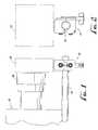
- FIG. 2is a front elevation view of the multi-jaw clamp with the matte box assembly mounted on the clamp;
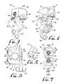
- FIG. 3is an isometric view of the back of the clamp with the clamp in the open position
- FIG. 4is an isometric view of the front of the clamp with the clamp in the open position
- FIG. 5is an isometric view of the multi-jaw cylinder
- FIG. 6is a front elevation view of the clamp in the closed position
- FIG. 7is a top plan view of the clamp in the closed position
- FIGS. 8A-8Care plan views of the multi-jaw cylinders juxtaposed in three different positions for fitting three different sizes of iris rods;
- FIG. 9is a cross-sectional view taken along the line 9 — 9 in FIG. 7 and showing the clamp in the closed position around a rod;
- FIG. 10is a cross-sectional view taken along the line 10 — 10 in FIG. 9 and showing the clamp in the closed position around a rod.
- FIG. 1is a top plan view of the multi-jaw clamp 10 according to a preferred embodiment mounted to a camera 12 on an iris rod 14 projecting forwardly of the camera 12 with a matte box assembly 16 attached to the clamp.
- a cameramay be provided with two iris rods and such case there will be two clamps 10 .
- the multi jaw clamp 10includes a threaded hole 18 (best viewed in FIG. 9) for mounting the matte box assembly to the clamp so that the matte box is positioned in front of the camera lens 20 .
- the multi-jaw clamp 10includes a hinge assembly 22 that permits the clamp to open and close around the iris rod 14 as viewed in FIG. 2 .
- the clamp 10is provided with two housings 30 and 32 that are connected by the hinge assembly 22 , which allows the housings to open and close around the iris rod 14 .
- the hinge assembly 22includes the hinge section 34 of housing 30 and the hinge section 36 of housing 32 , each of which hinge sections have holes through them to accommodate the hinge pin 38 extending the length of the hinge assembly 22 .
- the ends of each of the hinge sections 34 and 36are curved to accommodate the opening and closing of the clamp. Any mechanism similar to a hinge that will allow relative movement of housings 30 and 32 in the unlatched condition, as described below, but prevents separation in the latched condition may be used in place of hinge assembly 22 .
- the housing 30is generally rectangularly shaped and has a semi-circular channel 40 cut into the long side of the housing and runs the length of the short side of the housing.
- the housing 30also contains a cylindrical hole 42 (best viewed in FIGS. 6 and 10) in the housing on the side opposite the hinge section 34 and cuts through the semi-circular channel 40 .
- the cylindrical hole 42does not penetrate through the side of the housing adjacent to the hinge section 34 .
- the cylindrical hole 42is sized to receive the multi-jaw cylinder 50 (best viewed in FIG. 10 ).
- the housing 30also contains a rectangular shaped protrusion 52 on the side opposed to the semicircular channel 40 that contains a threaded hole 18 (shown in FIG. 9) for attaching a matte box assembly 16 or other items to the housing.
- the housing 32 as shown in FIG. 3,is also generally rectangular in shape and has a semi-circular channel 54 , similar to channel 40 , cut into the long side of the housing, which hole runs the entire length of the short side of the housing.
- the housing 32also contains a cylindrical hole 42 (the same as hole 42 in housing 30 ) in the housing on the side opposed to the hinge section 36 and cuts through the semi-circular channel 54 .
- the cylindrical hole 42does not penetrate through the side of the housing adjacent to the hinge section 36 .
- the cylindrical hole 42is sized to receive another multi-jaw cylinder 50 (best viewed in FIG. 10 ).
- cover plates 58 and 56are threadably connected to the housings.
- the platescover cylindrical holes 42 in both housings.
- Cover plate 56contains a hole that runs along the vertical length of the plate and opens toward housing 30 .
- the holeis sized to receive a threaded bolt 60 so that the bolt can pass through the plate 56 and extend beyond the end of the plate.
- the side of the bolt opposed to housing 30contains a handle 62 so that the bolt can be easily turned by hand.
- Cover plate 58contains a threaded hole 59 that opens toward housing 32 and is sized and threaded to receive the end of bolt 60 that extends past cover plate 56 .
- Each multi-jaw cylinder 50is sized to fit within the cylindrical hole 42 in housings 30 and 32 .
- the cylinder 50contains a stem 64 protruding from one end to receive a selector 66 after the cylinder is placed in the housing.
- the stem 64contains a square-shaped end for attaching the selector 66 to the stem.
- the cylinderas shown in the preferred embodiment, has three curved sections 68 cut into the sides of the cylinder approximately 120° apart.
- the cylindercould be made with as few as two curved sections and could be made with more than three curved sections.
- Each curved section 68 on the cylinderhas a different radius, so that when they are placed in the housing, they can be rotated into one of three positions to precisely fit one of three different diameters of rods.
- a size indicator 70Aligned with the center of each of the curved sections is a size indicator 70 marked on the end of the cylinder containing the stem 64 .
- Adjacent the size indicatoris a v-shaped notch 72 that runs along the side of the cylinder from the end containing the stem to the curved section 68 .
- the clampis shown in the closed position with the multi-jaw cylinders 50 inside the housings 30 and 32 .
- the multi-jaw cylinders 50are shown with the selectors 66 attached to the stem 64 .
- Housings 30 and 32contain holes 74 in the sides opposite the cover plates 56 and 58 sized to receive the stems 64 of the cylinders 50 .
- the curved sections 68in the preferred embodiment, will have diameters of approximately 0.591 in, 0.622 in. and 0.748 in to fit on conventional iris rods of those diameters. The diameters of the curved sections, however, can be of any size as needed to accommodate the size of the rods that the clamp will be attached to.
- the diameter of the semi-circular channels 40 and 54will be larger than the largest diameter of the curved sections 68 on the multi-jaw cylinders 50 to insure that the curved sections 68 extend into the curved channels 40 and 54 for the multi-jaw cylinders to engage the iris rod 14 without the iris rod engaging the housings.
- FIG. 7the top view of the clamp is shown. Adjacent to the hole 74 in each of the housings is a hole 76 so that the size indicator 70 is visible. As the selector 66 is turned, each of the three size indicators comes into view through the hole 76 , which indicators may be numbers, letters or colors. Once the desired diameter is selected and the size indicator is viewable through hole 76 , the multi-jaw cylinder is precisely located and inhibited from further rotation by a ball and spring detent mechanism 78 in which the ball engages the v-shaped notch 72 on the multi-jaw cylinder 50 . The mechanisms 78 are located and retained by setscrews 79 in threaded holes 80 , which are located in the housings 30 and 32 .
- the hole 80is located so that the ball of the mechanism 78 will engage the v-shaped notch 72 that is aligned with the curved section 68 that is adjacent to the curved section currently selected.
- the setscrew 79As the setscrew 79 is rotated, it comes into contact with the spring for adjusting the resilient force applied to the ball and, in turn, on the v-shaped notch 72 on the cylinder and inhibits the cylinder from further rotation.
- the setscrew, 79may be longer and directly engage the cylinder 50 , with or without a notch 72 .
- FIGS. 8A-8Cdiagrammatically indicate the various matching positions of the multi-jaw cylinders 50 apart from the housings 30 and 32 .
- the two cylinders 50are in positions so that smallest radius curved sections 68 on the multi-jaw cylinders are aligned. In this position, the multi-jaw clamp would engage with the smallest diameter rod.
- the two cylinders 50are in positions so that the largest radius curved sections 68 are aligned. In this position, the multi-jaw clamp would engage with a rod with the largest diameter.
- FIG. 8Cthe two cylinders 50 are in positions so that the intermediate curved sections 68 are aligned. In this position, the multi-jaw clamp would engage with a rod with the intermediate sized diameter that the clamp could engage.
- FIG. 9a cross-section of the clamp in the closed position taken along line 9 — 9 in FIG. 7 is shown.
- the multi-jaw clamp 10is slid onto or hinged open and placed on the iris rod 14 .
- the multi-jaw cylinders 50are shown in each housing with an iris rod 14 engaged between the cylinders.
- Threaded bolt 60is threadably engaged with the threaded hole 59 to lock the clamp in the closed position and tightly on the iris rod in the desired axial position.
- the threaded hole 18 in the protrusion 52 on housing 30that can be used to attach a matte box 16 or other items.
- FIG. 10also shows a cross sectional view of the clamp taken along line 10 — 10 in FIG. 9 .
- the cylindrical hole 42 to receive the multi-jaw cylinders 50also are shown.
Landscapes
- Engineering & Computer Science (AREA)
- General Engineering & Computer Science (AREA)
- Mechanical Engineering (AREA)
- Clamps And Clips (AREA)
Abstract
Description
Claims (27)
Priority Applications (1)
| Application Number | Priority Date | Filing Date | Title |
|---|---|---|---|
| US09/802,836US6450465B1 (en) | 2001-03-08 | 2001-03-08 | Multi-jaw clamp |
Applications Claiming Priority (1)
| Application Number | Priority Date | Filing Date | Title |
|---|---|---|---|
| US09/802,836US6450465B1 (en) | 2001-03-08 | 2001-03-08 | Multi-jaw clamp |
Publications (2)
| Publication Number | Publication Date |
|---|---|
| US20020125388A1 US20020125388A1 (en) | 2002-09-12 |
| US6450465B1true US6450465B1 (en) | 2002-09-17 |
Family
ID=25184845
Family Applications (1)
| Application Number | Title | Priority Date | Filing Date |
|---|---|---|---|
| US09/802,836Expired - LifetimeUS6450465B1 (en) | 2001-03-08 | 2001-03-08 | Multi-jaw clamp |
Country Status (1)
| Country | Link |
|---|---|
| US (1) | US6450465B1 (en) |
Cited By (21)
| Publication number | Priority date | Publication date | Assignee | Title |
|---|---|---|---|---|
| US6796608B2 (en)* | 2002-10-09 | 2004-09-28 | Kenneth J. Ventimiglia | Tennis “ teaching-seat” assembly |
| US20040238703A1 (en)* | 2003-03-12 | 2004-12-02 | Yinka Davies | Clamps |
| US20050040304A1 (en)* | 2003-08-22 | 2005-02-24 | Hall Jacob R. | Fixing apparatus |
| US20060290515A1 (en)* | 2005-06-23 | 2006-12-28 | Jukka Kankkunen | Fastening means for a patient monitor |
| US20070222209A1 (en)* | 2004-09-13 | 2007-09-27 | Brian Rise | Pipe Clamp for a Reinforcement Grid, Preferabley in Connection with Floor Heating Installations |
| US20080230238A1 (en)* | 2007-03-22 | 2008-09-25 | The Viking Corporation | Mounting Coupling For Sprinkler Support System |
| US20100206965A1 (en)* | 2009-02-13 | 2010-08-19 | Gibowski Steven R | Adjustable, multiple splash plate liquor guns |
| US20100252702A1 (en)* | 2009-04-06 | 2010-10-07 | Baxter International Inc. | Rapid attach and release clamps |
| US20100302655A1 (en)* | 2009-05-26 | 2010-12-02 | Jerry Paul Hill | Lens Drive Motor Mount |
| US20110284098A1 (en)* | 2010-05-20 | 2011-11-24 | Pnm, Inc. | Hub with locking mechanism |
| US20120084945A1 (en)* | 2010-10-06 | 2012-04-12 | Chi-Perng Liu | Locking device |
| US20120102685A1 (en)* | 2010-11-02 | 2012-05-03 | Keller Brian K | Shaft Clamp |
| US20130048822A1 (en)* | 2011-08-24 | 2013-02-28 | Victaulic Company | Bracket |
| US9206903B2 (en)* | 2011-11-22 | 2015-12-08 | Seal Ryt Corp. | Locking collar for cylindrical cavity |
| US9541108B1 (en)* | 2013-11-21 | 2017-01-10 | Julie Beth Penrod | Anchor system for securing attachments to handles |
| US9889327B2 (en) | 2014-06-27 | 2018-02-13 | Flexhead Industries, Inc. | Adjustable bracket and hub for flexible hose support |
| US10016644B2 (en)* | 2015-04-08 | 2018-07-10 | Dongwoo Flexible Metal Tube Co., Ltd. | End bracket for sprinkler and fixing apparatus for sprinkler including the same |
| US10059312B1 (en)* | 2017-04-26 | 2018-08-28 | George Kehder | Swinging mount for trailer jack |
| US11168834B2 (en) | 2018-12-17 | 2021-11-09 | Victaulic Company | Reversible bracket |
| US11198489B2 (en)* | 2013-01-03 | 2021-12-14 | Benjamin Dodge | Rope clasp |
| US20220301447A1 (en)* | 2021-03-17 | 2022-09-22 | Gregory M. Griffith | Sensor assembly for use in association with aircraft collision avoidance system and method of using the same |
Families Citing this family (17)
| Publication number | Priority date | Publication date | Assignee | Title |
|---|---|---|---|---|
| US6789557B1 (en)* | 2001-06-25 | 2004-09-14 | Gene Wahl, Jr. | Portable and collapsible sunshade apparatus for providing shade to a user having a universal clip to attach the sunshade to any type of beach chair or lounge chair |
| US7243990B1 (en) | 2006-07-24 | 2007-07-17 | Gene Wahl | Sunshade apparatus |
| US20080018146A1 (en)* | 2006-07-24 | 2008-01-24 | Eugene Wahl | Sunshade apparatus |
| US7988173B2 (en)* | 2008-09-05 | 2011-08-02 | Sram, Llc | Bicycle suspension system |
| US7926771B2 (en)* | 2008-10-31 | 2011-04-19 | Johnson Outdoors Inc. | Mounting apparatus for mounting objects to support structures of a tent |
| CN201328515Y (en)* | 2008-12-26 | 2009-10-21 | 厦门进雄企业有限公司 | Folding bar counter/folding desk |
| JP5610431B2 (en)* | 2009-10-26 | 2014-10-22 | 株式会社ニフコ | Axial support structure, clip, and support structure mold |
| US20110140471A1 (en)* | 2009-12-11 | 2011-06-16 | Ned Suesse | Folding Motorcycle Mirror |
| US8820543B2 (en)* | 2011-01-16 | 2014-09-02 | Han-Ching Huang | Apparatus for displaying a bicycle on a post |
| US9550544B2 (en) | 2012-07-26 | 2017-01-24 | Shimano Inc. | Bicycle handlebar clamp assembly |
| ITBO20130421A1 (en)* | 2013-07-31 | 2015-02-01 | Martina Peruzzo | DOOR-BICYCLE WALL |
| US20150300386A1 (en)* | 2014-02-28 | 2015-10-22 | Micro World Corp. | Hinged Mounting Clamp System |
| EP3483461B1 (en)* | 2016-07-06 | 2023-03-08 | Canon Denshi Kabushiki Kaisha | Uncoupling device |
| AU2020211991A1 (en)* | 2019-01-22 | 2021-09-09 | Core-Arms, LLC | Mounting system, devices, methods and uses thereof |
| USD920773S1 (en)* | 2019-04-04 | 2021-06-01 | David L. McClung | Clamping assembly |
| USD920772S1 (en)* | 2019-04-04 | 2021-06-01 | David L. McClung | Clamping assembly |
| US20220100061A1 (en)* | 2021-12-11 | 2022-03-31 | Components Express, Inc. | Securing Bracket |
Citations (1)
| Publication number | Priority date | Publication date | Assignee | Title |
|---|---|---|---|---|
| US2621384A (en)* | 1951-11-05 | 1952-12-16 | Cicero C Brown | Pipe clamp |
- 2001
- 2001-03-08USUS09/802,836patent/US6450465B1/ennot_activeExpired - Lifetime
Patent Citations (1)
| Publication number | Priority date | Publication date | Assignee | Title |
|---|---|---|---|---|
| US2621384A (en)* | 1951-11-05 | 1952-12-16 | Cicero C Brown | Pipe clamp |
Cited By (35)
| Publication number | Priority date | Publication date | Assignee | Title |
|---|---|---|---|---|
| US6796608B2 (en)* | 2002-10-09 | 2004-09-28 | Kenneth J. Ventimiglia | Tennis “ teaching-seat” assembly |
| US20040238703A1 (en)* | 2003-03-12 | 2004-12-02 | Yinka Davies | Clamps |
| US20050040304A1 (en)* | 2003-08-22 | 2005-02-24 | Hall Jacob R. | Fixing apparatus |
| US6926242B2 (en)* | 2003-08-22 | 2005-08-09 | Cateye Co., Ltd. | Fixing apparatus |
| US20070222209A1 (en)* | 2004-09-13 | 2007-09-27 | Brian Rise | Pipe Clamp for a Reinforcement Grid, Preferabley in Connection with Floor Heating Installations |
| US20060290515A1 (en)* | 2005-06-23 | 2006-12-28 | Jukka Kankkunen | Fastening means for a patient monitor |
| US7712713B2 (en)* | 2005-06-23 | 2010-05-11 | General Electric Company | Fastening means for a patient monitor |
| US7845599B2 (en)* | 2007-03-22 | 2010-12-07 | The Viking Corporation | Mounting coupling for sprinkler support system |
| US20080230238A1 (en)* | 2007-03-22 | 2008-09-25 | The Viking Corporation | Mounting Coupling For Sprinkler Support System |
| US20100206965A1 (en)* | 2009-02-13 | 2010-08-19 | Gibowski Steven R | Adjustable, multiple splash plate liquor guns |
| US8381667B2 (en)* | 2009-02-13 | 2013-02-26 | Alstom Technology Ltd | Adjustable, multiple splash plate liquor guns |
| US20100252702A1 (en)* | 2009-04-06 | 2010-10-07 | Baxter International Inc. | Rapid attach and release clamps |
| US8167259B2 (en)* | 2009-04-06 | 2012-05-01 | Baxter International Inc. | Rapid attach and release clamps |
| US20100302655A1 (en)* | 2009-05-26 | 2010-12-02 | Jerry Paul Hill | Lens Drive Motor Mount |
| US8085481B2 (en)* | 2009-05-26 | 2011-12-27 | Jerry Paul Hill | Lens drive motor mount |
| US20110284098A1 (en)* | 2010-05-20 | 2011-11-24 | Pnm, Inc. | Hub with locking mechanism |
| US8272615B2 (en)* | 2010-05-20 | 2012-09-25 | Flexhead Industries, Inc. | Hub with locking mechanism |
| US20120084945A1 (en)* | 2010-10-06 | 2012-04-12 | Chi-Perng Liu | Locking device |
| US8408507B2 (en)* | 2010-10-06 | 2013-04-02 | Chi-Perng Liu | Locking device |
| US20120102685A1 (en)* | 2010-11-02 | 2012-05-03 | Keller Brian K | Shaft Clamp |
| US8979051B2 (en)* | 2010-11-02 | 2015-03-17 | Brian K. Keller | Shaft clamp |
| US20130048822A1 (en)* | 2011-08-24 | 2013-02-28 | Victaulic Company | Bracket |
| US9278238B2 (en)* | 2011-08-24 | 2016-03-08 | Victaulic Company | Bracket |
| US9206903B2 (en)* | 2011-11-22 | 2015-12-08 | Seal Ryt Corp. | Locking collar for cylindrical cavity |
| US11198489B2 (en)* | 2013-01-03 | 2021-12-14 | Benjamin Dodge | Rope clasp |
| US9541108B1 (en)* | 2013-11-21 | 2017-01-10 | Julie Beth Penrod | Anchor system for securing attachments to handles |
| US10744357B2 (en) | 2014-06-27 | 2020-08-18 | Anvil International, Llc | Adjustable bracket and hub for flexible hose support |
| US10500427B2 (en) | 2014-06-27 | 2019-12-10 | Anvil International, Llc | Adjustable bracket and hub for flexible hose support |
| US10792526B2 (en) | 2014-06-27 | 2020-10-06 | Anvil International, Llc | Adjustable bracket and hub for flexible hose support |
| US9889327B2 (en) | 2014-06-27 | 2018-02-13 | Flexhead Industries, Inc. | Adjustable bracket and hub for flexible hose support |
| US10016644B2 (en)* | 2015-04-08 | 2018-07-10 | Dongwoo Flexible Metal Tube Co., Ltd. | End bracket for sprinkler and fixing apparatus for sprinkler including the same |
| US10059312B1 (en)* | 2017-04-26 | 2018-08-28 | George Kehder | Swinging mount for trailer jack |
| US11168834B2 (en) | 2018-12-17 | 2021-11-09 | Victaulic Company | Reversible bracket |
| US20220301447A1 (en)* | 2021-03-17 | 2022-09-22 | Gregory M. Griffith | Sensor assembly for use in association with aircraft collision avoidance system and method of using the same |
| US11682313B2 (en)* | 2021-03-17 | 2023-06-20 | Gregory M. Griffith | Sensor assembly for use in association with aircraft collision avoidance system and method of using the same |
Also Published As
| Publication number | Publication date |
|---|---|
| US20020125388A1 (en) | 2002-09-12 |
Similar Documents
| Publication | Publication Date | Title |
|---|---|---|
| US6450465B1 (en) | Multi-jaw clamp | |
| US6234690B1 (en) | Camera quick-release device | |
| US10599020B2 (en) | Swivel camera mount locking mechanism | |
| US10174879B2 (en) | Clamping mechanism and gimbal having the clamping mechanism | |
| US10352068B2 (en) | Cable locking device | |
| US8085481B2 (en) | Lens drive motor mount | |
| EP1160499A1 (en) | Camera-to-tripod quick-release mounting | |
| JP3443919B2 (en) | Lens mount device | |
| US4851621A (en) | Operating handle for an enclosed electric switch | |
| US7318272B1 (en) | Universal end connector attachment tool and method of use | |
| US3986635A (en) | Closure locking and orienting device | |
| US11229267B2 (en) | Key holder | |
| JP2012107747A (en) | Screw-operated clamping mechanism and method of using the same | |
| MXPA01010901A (en) | A closure casing. | |
| BRPI0612377A2 (en) | security device for coaxial cable ports and resulting method of use | |
| US4756405A (en) | Artist brush box | |
| US4441348A (en) | Key retaining device | |
| US5666253A (en) | Protective shield for electrical hot stick | |
| US20140170894A1 (en) | Twist Lock Connector Locking Mechanism | |
| JP2003344926A (en) | Lens mount device | |
| US6094120A (en) | Magnetizing apparatus | |
| US7824425B2 (en) | Ambidextrous locking clamp system | |
| US6382801B1 (en) | Submarine periscope eyeguard housing assembly | |
| DE3625986C1 (en) | Marking plate carrier for a plug housing | |
| GB2122678A (en) | Improvements in or relating to releasable fasteners |
Legal Events
| Date | Code | Title | Description |
|---|---|---|---|
| AS | Assignment | Owner name:PANAVISION, INC., CALIFORNIA Free format text:ASSIGNMENT OF ASSIGNORS INTEREST;ASSIGNOR:ESLICK, WILLIAM R.;REEL/FRAME:011598/0160 Effective date:20010302 | |
| AS | Assignment | Owner name:JPMORGAN CHASE BANK, AS ADMINISTRATIVE AGENT, TEXA Free format text:SECURITY INTEREST;ASSIGNOR:PANAVISION INC. (DE CORPORATION);REEL/FRAME:012983/0510 Effective date:20020507 | |
| STCF | Information on status: patent grant | Free format text:PATENTED CASE | |
| FEPP | Fee payment procedure | Free format text:PAYOR NUMBER ASSIGNED (ORIGINAL EVENT CODE: ASPN); ENTITY STATUS OF PATENT OWNER: LARGE ENTITY | |
| AS | Assignment | Owner name:WILMINGTON TRUST, AS COLLATERAL TRUSTEE, DELAWARE Free format text:COLLATERAL AGREEMENT;ASSIGNORS:PANAVISION INC.;PANAPAGE ONE LLC;PANAPAGE TWO LLC;AND OTHERS;REEL/FRAME:014294/0009 Effective date:20040116 | |
| FPAY | Fee payment | Year of fee payment:4 | |
| AS | Assignment | Owner name:PANAVISION INC., CALIFORNIA Free format text:RELEASE BY SECURED PARTY;ASSIGNOR:WILMINGTON TRUST COMPANY;REEL/FRAME:017388/0409 Effective date:20060329 Owner name:PANAVISION U.K. HOLDINGS, INC., CALIFORNIA Free format text:RELEASE BY SECURED PARTY;ASSIGNOR:WILMINGTON TRUST COMPANY;REEL/FRAME:017388/0409 Effective date:20060329 Owner name:PANAVISION REMOTE SYSTEMS, LLC, CALIFORNIA Free format text:RELEASE BY SECURED PARTY;ASSIGNOR:WILMINGTON TRUST COMPANY;REEL/FRAME:017388/0409 Effective date:20060329 Owner name:PANAPAGE CO. LLC, CALIFORNIA Free format text:RELEASE BY SECURED PARTY;ASSIGNOR:WILMINGTON TRUST COMPANY;REEL/FRAME:017388/0409 Effective date:20060329 Owner name:PANAPAGE INTERNATIONAL, L.P., CALIFORNIA Free format text:RELEASE BY SECURED PARTY;ASSIGNOR:WILMINGTON TRUST COMPANY;REEL/FRAME:017388/0409 Effective date:20060329 Owner name:LAS PALMAS PRODUCTIONS, INC., CALIFORNIA Free format text:RELEASE BY SECURED PARTY;ASSIGNOR:WILMINGTON TRUST COMPANY;REEL/FRAME:017388/0409 Effective date:20060329 Owner name:PANAPAGE ONE LLC, CALIFORNIA Free format text:RELEASE BY SECURED PARTY;ASSIGNOR:WILMINGTON TRUST COMPANY;REEL/FRAME:017388/0409 Effective date:20060329 Owner name:PANAPAGE TWO LLC, CALIFORNIA Free format text:RELEASE BY SECURED PARTY;ASSIGNOR:WILMINGTON TRUST COMPANY;REEL/FRAME:017388/0409 Effective date:20060329 | |
| AS | Assignment | Owner name:PANAVISION INC., CALIFORNIA Free format text:RELEASE BY SECURED PARTY;ASSIGNOR:JPMORGAN CHASE BANK, N.A.;REEL/FRAME:017411/0770 Effective date:20060329 | |
| AS | Assignment | Owner name:CREDIT SUISSE, AS FIRST LIEN COLLATERAL AGENT, NEW Free format text:SECURITY AGREEMENT;ASSIGNORS:PANAVISION INC.;PANAVISION INTERNATIONAL, L.P.;REEL/FRAME:017468/0678 Effective date:20060330 | |
| AS | Assignment | Owner name:CREDIT SUISSE, AS SECOND LIEN COLLATERAL AGENT, NE Free format text:SECURITY AGREEMENT;ASSIGNORS:PANAVISION INC.;PANAVISION INTERNATIONAL, L.P.;REEL/FRAME:017480/0803 Effective date:20060330 | |
| FPAY | Fee payment | Year of fee payment:8 | |
| FPAY | Fee payment | Year of fee payment:12 | |
| AS | Assignment | Owner name:BANK OF AMERICA, N.A., AS AGENT AND U.S. LENDER, C Free format text:SECURITY INTEREST;ASSIGNORS:PANAVISION INC.;PANAVISION INTERNATIONAL, L.P.;LIGHT IRON DIGITAL, LLC;AND OTHERS;REEL/FRAME:037693/0662 Effective date:20160205 | |
| AS | Assignment | Owner name:PANAVISION INTERNATIONAL, L.P., CALIFORNIA Free format text:RELEASE BY SECURED PARTY;ASSIGNOR:CREDIT SUISSE, AS SECOND LIEN COLLATERAL AGENT;REEL/FRAME:037846/0116 Effective date:20160225 Owner name:PANAVISION INC., CALIFORNIA Free format text:RELEASE BY SECURED PARTY;ASSIGNOR:CREDIT SUISSE, AS SECOND LIEN COLLATERAL AGENT;REEL/FRAME:037846/0116 Effective date:20160225 | |
| AS | Assignment | Owner name:ALTER DOMUS (US) LLC, ILLINOIS Free format text:SECURITY INTEREST;ASSIGNORS:PANAVISION INC.;PANAVISION INTERNATIONAL, L.P.;LIGHT IRON DIGITAL, LLC;AND OTHERS;REEL/FRAME:054285/0199 Effective date:20201029 | |
| AS | Assignment | Owner name:COURTLAND CAPITAL MARKET SERVICES LLC, ILLINOIS Free format text:ASSIGNMENT OF ASSIGNORS INTEREST;ASSIGNOR:CREDIT SUISSE AG, CAYMAN ISLANDS BRANCH AS RETIRED AGENT;REEL/FRAME:060932/0054 Effective date:20220829 | |
| AS | Assignment | Owner name:PANAVISION INTERNATIONAL, L.P., CALIFORNIA Free format text:RELEASE BY SECURED PARTY;ASSIGNOR:CORTLAND CAPITAL MARKET SERVICES LLC;REEL/FRAME:060951/0548 Effective date:20220829 Owner name:PANAVISION INC., CALIFORNIA Free format text:RELEASE BY SECURED PARTY;ASSIGNOR:CORTLAND CAPITAL MARKET SERVICES LLC;REEL/FRAME:060951/0548 Effective date:20220829 |