US6450270B1 - Rotary cone bit for cutting removal - Google Patents
Rotary cone bit for cutting removalDownload PDFInfo
- Publication number
- US6450270B1 US6450270B1US09/669,998US66999800AUS6450270B1US 6450270 B1US6450270 B1US 6450270B1US 66999800 AUS66999800 AUS 66999800AUS 6450270 B1US6450270 B1US 6450270B1
- Authority
- US
- United States
- Prior art keywords
- plateau
- bearing pin
- longitudinal axis
- bit
- rotary cone
- Prior art date
- Legal status (The legal status is an assumption and is not a legal conclusion. Google has not performed a legal analysis and makes no representation as to the accuracy of the status listed.)
- Expired - Lifetime
Links
Images


Classifications
- E—FIXED CONSTRUCTIONS
- E21—EARTH OR ROCK DRILLING; MINING
- E21B—EARTH OR ROCK DRILLING; OBTAINING OIL, GAS, WATER, SOLUBLE OR MELTABLE MATERIALS OR A SLURRY OF MINERALS FROM WELLS
- E21B10/00—Drill bits
- E21B10/08—Roller bits
- E21B10/18—Roller bits characterised by conduits or nozzles for drilling fluids
- E—FIXED CONSTRUCTIONS
- E21—EARTH OR ROCK DRILLING; MINING
- E21B—EARTH OR ROCK DRILLING; OBTAINING OIL, GAS, WATER, SOLUBLE OR MELTABLE MATERIALS OR A SLURRY OF MINERALS FROM WELLS
- E21B10/00—Drill bits
- E21B10/08—Roller bits
- E—FIXED CONSTRUCTIONS
- E21—EARTH OR ROCK DRILLING; MINING
- E21B—EARTH OR ROCK DRILLING; OBTAINING OIL, GAS, WATER, SOLUBLE OR MELTABLE MATERIALS OR A SLURRY OF MINERALS FROM WELLS
- E21B17/00—Drilling rods or pipes; Flexible drill strings; Kellies; Drill collars; Sucker rods; Cables; Casings; Tubings
- E21B17/10—Wear protectors; Centralising devices, e.g. stabilisers
- E21B17/1092—Gauge section of drill bits
Definitions
- the present inventionrelates to rotary cone bits, and in particular to a rotary cone bit having a bit body for enhanced cutting removal.
- Rotary cone bitsare well known in the art of drilling.
- the most common design of a rolling cone bitconsists of three generally conical shaped cutters, each rotatably mounted on a downwardly extending bearing pin.
- Each of the bearing pinsis spaced approximately 120° apart with the three pins formed as a part of a bit body.
- the entire structureis rotated at the end of a drill string. Boring is accomplished by applying weight to the drill bit and rotating the drill string, thereby causing the cutters to roll and crush the rock formation beneath the bit.
- the cutter elementscontact and disintegrate portions of the formation in order to form the desired bore hole.
- a large portion of the cuttings produced by the drilling operationare in the form of finely divided particles which create a highly abrasive environment.
- These cuttings from the bottom and sides of the bore holeare washed away by a drilling fluid, such as air or drill mud, that is supplied to the drill bit from the surface through the hollow rotating drill string.
- the cuttingsare carried to the surface suspended in the drilling fluid.
- the grinding and re-grinding of the cuttings produced by the drilling operationslows the formation penetration rate of the bit and shortens the life of the bit.
- the re-ground cuttingstend to dull the cutters and the finely ground particles are forced into the bearing surfaces formed between the roller cones and the journals supported by the bit, further limiting bit life.
- the drilling fluideither drilling mud or air
- the drilling fluidis directed by nozzles against the cutter cones to wash the cuttings from the cutter cone and the bore hole.
- the direction of the drilling fluid against the cutter coneresults in trapping some of the cuttings along the bottom of the hole with the result that the cuttings are re-ground to an abrasive powder before removal.
- an improved rotary cone bithaving a threaded end for coupling to a drill string and including a drill bit body having two or more leg portions extending from one end of the body. Formed integral with each of the leg portions is a bearing pin that extends inwardly toward the longitudinal axis of the drill bit body. On each of the bearing pins, there is rotatably mounted a cutter cone having rows of cutting teeth as a part thereof.
- the bit shirttailcomprises a plateau extending along the longitudinal axis in substantially the same plane as the bearing pin surface area of the shirttail.
- the improved rotary cone bit of the present inventioncomprises a plateau on each of the leg portions of the bit body.
- the plateauis part of the shirttail of the leg portion and extends along the longitudinal axis of the bit from the bearing pin surface area to the threaded end.
- the surface of the plateauextends in substantially the same plane as the bearing pin surface area until a break point at which the plateau tapers to the threaded end.
- the break pointis about between one-third to two-thirds of the length of the plateau from the bearing pin surface area to the threaded end.
- the improved rotary cone bit of the present inventionincludes a first contoured surface on the leg portion wherein the first contoured surface is contiguous to the plateau and has a longitudinal axis substantially parallel to the longitudinal axis of the bit body.
- the first contoured surfaceis angled down and away from the plateau and extends from the bearing pin surface area to the threaded end.
- a second contoured surface also formed on the shirttail of the leg portionis contiguous to the plateau and has a longitudinal axis substantially parallel to the longitudinal axis of the bit body. This second contoured surface is angled down and away from the plateau and extends from the bearing pin surface area to the threaded end.
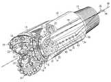
- FIG. 1is a perspective view of a rotary cone bit with improved chip removal enhancements
- FIG. 2is a partial cross-section through the shirttail of a leg portion of the rotary cone bit of FIG. 1 illustrating the shirttail plateau and contiguous contoured surfaces;
- FIG. 3is a partial side view of a leg portion of the rotary cone bit of FIG. 1 further showing the plateau and contiguous contoured surfaces.
- a rotary cone bithaving a contoured shirttail for enhanced cutting removal from a bore hole.
- the rotary cone bit of the present inventionincludes a bit body having a central vertical axis and a threaded shank for connection to a drill string.
- the shankis formed on one end of the bit body and includes a central vertical axis coaxial with the central vertical axis of the bit body.
- a bearing pinis formed integral to each of the three respective leg portions and extends inwardly and downwardly approximately toward the central vertical axis of the bit body.
- Each bearing pinterminates in a bearing pin surface area as a part of the shirttail.
- a rolling cutteris rotatably mounted on each respective bearing pin in accordance with conventional sealing and cutter retaining techniques.
- the shirttail of each leg portionincludes a longitudinal axis approximately intersecting the vertical axis of the bit body. Extending along this longitudinal axis for each of the bearing pins is a ridge surface or plateau from the bearing pin surface area to the threaded shank. This ridge surface or plateau extends in substantially the same plane as the bearing pin surface area from about one-third to two-thirds of the distance between the bearing pin surface area and the threaded shank. The ridge surface or plateau then tapers to the threaded shank. On either side of the ridge surface or plateau there is integrally formed therewith a contoured surface having a longitudinal axis substantially parallel to the longitudinal axis of the plateau.
- a rotary cone bitincluding a bit body 10 having at one end a threaded shank 12 for attachment to a drill string member (not shown).
- the threaded shank 12is adapted to be threadably engaged with a drill string in accordance with conventional drill bit construction.
- Extending from the bit body 10are three leg portions 14 providing support for a rotatable roller cutter cone 16 .
- Both the bit body 10 and the shank 12have an axially extending hollow passage terminating in nozzles 20 (only one shown) for directing drilling fluid, such as drilling mud or air, to flush the bore hole of debris during the drilling operation.
- the passageterminates in nozzles 20 positioned between each of the three cones.
- Each of the nozzlesis surrounded by a hard facing ring 21 for improved wear resistance against debris circulating around the drill bit during a drilling operation in a bore hole.
- the roller cutter cones 16have substantially the same base diameter to permit the cutting teeth on each cone to project between the cutting teeth of the other cutter cones.
- the cutting teeth 22 on each of the cutter cones 16are arranged in rows and in the embodiment shown comprise tungsten carbide inserts press fit into the cone surface and projecting therefrom.
- Each of the cutter cones 16is also provided with gage row teeth 24 such as carbine insert press fit into the cone surface and projecting therefrom.
- the cutter cones 16are journaled on respective leg portions 14 for rotation about a rotational axis of a bearing pin. This axis of rotation is inclined with respect to the vertical axis of the bit in accordance with conventional roller cone cutter techniques.
- the bearing structure and seal assembly for each of the cutter cones 16is of a conventional design.
- each leg portion 14includes a ridge surface or plateau 30 having a surface in substantially the same plane as a bearing pin surface area 32 and extending from the bearing pin surface area to a tapered surface 34 terminating at the threaded shank 12 at substantially the same dimension thereof.
- a longitudinal axis 36 of the tapered surface 34intersects the longitudinal axis 38 of the threaded shank 12 and the bit body 10 .
- the longitudinal axis 36is an extension of a longitudinal axis 40 of the ridge surface or plateau 30 .
- Each of the bearing pinsis similarly configured to include the plateau 30 and the tapered surface 36 .
- the ridge surface or plateau 30 and the bearing pin surface area 32have a pattern of wear inserts 42 press fit into the surface of the ridge and the surface area. These wear inserts 42 provide additional wear resistance to the leg portion 14 as the drill bit rotates in a bore hole.
- a contoured surface 44Contiguous with the ridge surface or plateau 30 on either side thereof is a contoured surface 44 having a first subsurface 44 a at substantially right angles to the plateau 30 and a second subsurface 44 b angled down and away from the plateau 30 .
- the longitudinal axis 46 of the contoured surface 44intersects the longitudinal axis 38 of the threaded shank 12 and the bit body 10 .
- the contour surface 44 on each side of the plateau 30is also angled down and away from the bearing pin surface area 32 to the diameter of the threaded shank 12 .
- the nozzles 20each have a discharge end positioned between adjacent leg portions to direct drilling fluid between the cutter cones for rock chip removal.
- Each of the nozzles 20terminates at the dome of the drill bit as formed by the assembly of the three leg portions.
Landscapes
- Engineering & Computer Science (AREA)
- Life Sciences & Earth Sciences (AREA)
- Geology (AREA)
- Mining & Mineral Resources (AREA)
- Mechanical Engineering (AREA)
- Physics & Mathematics (AREA)
- Environmental & Geological Engineering (AREA)
- Fluid Mechanics (AREA)
- General Life Sciences & Earth Sciences (AREA)
- Geochemistry & Mineralogy (AREA)
- Earth Drilling (AREA)
- Drilling Tools (AREA)
Abstract
Description
Claims (12)
Priority Applications (1)
| Application Number | Priority Date | Filing Date | Title |
|---|---|---|---|
| US09/669,998US6450270B1 (en) | 1999-09-24 | 2000-09-25 | Rotary cone bit for cutting removal |
Applications Claiming Priority (2)
| Application Number | Priority Date | Filing Date | Title |
|---|---|---|---|
| US15605999P | 1999-09-24 | 1999-09-24 | |
| US09/669,998US6450270B1 (en) | 1999-09-24 | 2000-09-25 | Rotary cone bit for cutting removal |
Publications (1)
| Publication Number | Publication Date |
|---|---|
| US6450270B1true US6450270B1 (en) | 2002-09-17 |
Family
ID=22557929
Family Applications (1)
| Application Number | Title | Priority Date | Filing Date |
|---|---|---|---|
| US09/669,998Expired - LifetimeUS6450270B1 (en) | 1999-09-24 | 2000-09-25 | Rotary cone bit for cutting removal |
Country Status (4)
| Country | Link |
|---|---|
| US (1) | US6450270B1 (en) |
| CA (1) | CA2320396A1 (en) |
| SE (1) | SE524046C2 (en) |
| ZA (1) | ZA200005048B (en) |
Cited By (35)
| Publication number | Priority date | Publication date | Assignee | Title |
|---|---|---|---|---|
| US20070144789A1 (en)* | 2005-10-25 | 2007-06-28 | Simon Johnson | Representation of whirl in fixed cutter drill bits |
| US20090272582A1 (en)* | 2008-05-02 | 2009-11-05 | Baker Hughes Incorporated | Modular hybrid drill bit |
| US20100006343A1 (en)* | 2008-07-09 | 2010-01-14 | Felderhoff Floyd C | Earth-boring tools having features for affecting cuttings flow and methods of forming the same |
| US20100122848A1 (en)* | 2008-11-20 | 2010-05-20 | Baker Hughes Incorporated | Hybrid drill bit |
| US7819208B2 (en) | 2008-07-25 | 2010-10-26 | Baker Hughes Incorporated | Dynamically stable hybrid drill bit |
| US7841426B2 (en) | 2007-04-05 | 2010-11-30 | Baker Hughes Incorporated | Hybrid drill bit with fixed cutters as the sole cutting elements in the axial center of the drill bit |
| US7845435B2 (en) | 2007-04-05 | 2010-12-07 | Baker Hughes Incorporated | Hybrid drill bit and method of drilling |
| US20110079442A1 (en)* | 2009-10-06 | 2011-04-07 | Baker Hughes Incorporated | Hole opener with hybrid reaming section |
| US8047307B2 (en) | 2008-12-19 | 2011-11-01 | Baker Hughes Incorporated | Hybrid drill bit with secondary backup cutters positioned with high side rake angles |
| US8056651B2 (en) | 2009-04-28 | 2011-11-15 | Baker Hughes Incorporated | Adaptive control concept for hybrid PDC/roller cone bits |
| US8141664B2 (en) | 2009-03-03 | 2012-03-27 | Baker Hughes Incorporated | Hybrid drill bit with high bearing pin angles |
| US8157026B2 (en) | 2009-06-18 | 2012-04-17 | Baker Hughes Incorporated | Hybrid bit with variable exposure |
| US8450637B2 (en) | 2008-10-23 | 2013-05-28 | Baker Hughes Incorporated | Apparatus for automated application of hardfacing material to drill bits |
| US8448724B2 (en) | 2009-10-06 | 2013-05-28 | Baker Hughes Incorporated | Hole opener with hybrid reaming section |
| US8459378B2 (en) | 2009-05-13 | 2013-06-11 | Baker Hughes Incorporated | Hybrid drill bit |
| US8471182B2 (en) | 2008-12-31 | 2013-06-25 | Baker Hughes Incorporated | Method and apparatus for automated application of hardfacing material to rolling cutters of hybrid-type earth boring drill bits, hybrid drill bits comprising such hardfaced steel-toothed cutting elements, and methods of use thereof |
| US8522899B2 (en) | 2010-10-01 | 2013-09-03 | Varel International, Ind., L.P. | Wear resistant material at the shirttail edge and leading edge of a rotary cone drill bit |
| US8528667B2 (en) | 2010-10-01 | 2013-09-10 | Varel International, Ind., L.P. | Wear resistant material at the leading edge of the leg for a rotary cone drill bit |
| US8534390B2 (en) | 2010-10-01 | 2013-09-17 | Varel International, Ind., L.P. | Wear resistant material for the shirttail outer surface of a rotary cone drill bit |
| US8678111B2 (en) | 2007-11-16 | 2014-03-25 | Baker Hughes Incorporated | Hybrid drill bit and design method |
| US8948917B2 (en) | 2008-10-29 | 2015-02-03 | Baker Hughes Incorporated | Systems and methods for robotic welding of drill bits |
| US8950514B2 (en) | 2010-06-29 | 2015-02-10 | Baker Hughes Incorporated | Drill bits with anti-tracking features |
| US8978786B2 (en) | 2010-11-04 | 2015-03-17 | Baker Hughes Incorporated | System and method for adjusting roller cone profile on hybrid bit |
| US9004198B2 (en) | 2009-09-16 | 2015-04-14 | Baker Hughes Incorporated | External, divorced PDC bearing assemblies for hybrid drill bits |
| WO2015065440A1 (en)* | 2013-10-31 | 2015-05-07 | Halliburton Energy Services, Inc. | Drill bit arm pocket |
| US20160108680A1 (en)* | 2014-10-20 | 2016-04-21 | Baker Hughes Incorporated | Reverse circulation hybrid bit |
| US9353575B2 (en) | 2011-11-15 | 2016-05-31 | Baker Hughes Incorporated | Hybrid drill bits having increased drilling efficiency |
| US9439277B2 (en) | 2008-10-23 | 2016-09-06 | Baker Hughes Incorporated | Robotically applied hardfacing with pre-heat |
| US9476259B2 (en) | 2008-05-02 | 2016-10-25 | Baker Hughes Incorporated | System and method for leg retention on hybrid bits |
| US9488007B2 (en) | 2010-10-01 | 2016-11-08 | Varel International Ind., L.P. | Wear resistant plates on a leading transitional surface of the leg for a rotary cone drill bit |
| US9782857B2 (en) | 2011-02-11 | 2017-10-10 | Baker Hughes Incorporated | Hybrid drill bit having increased service life |
| US10107039B2 (en) | 2014-05-23 | 2018-10-23 | Baker Hughes Incorporated | Hybrid bit with mechanically attached roller cone elements |
| WO2019020325A1 (en) | 2017-07-27 | 2019-01-31 | Sandvik Intellectual Property Ab | Rock bit having cuttings channels for flow optimization |
| US10364610B2 (en)* | 2016-08-09 | 2019-07-30 | Varel International Ind., L.P. | Durable rock bit for blast hole drilling |
| US10557311B2 (en) | 2015-07-17 | 2020-02-11 | Halliburton Energy Services, Inc. | Hybrid drill bit with counter-rotation cutters in center |
Citations (18)
| Publication number | Priority date | Publication date | Assignee | Title |
|---|---|---|---|---|
| US4802539A (en)* | 1984-12-21 | 1989-02-07 | Smith International, Inc. | Polycrystalline diamond bearing system for a roller cone rock bit |
| US4989680A (en)* | 1980-03-24 | 1991-02-05 | Camco International Inc. | Drill bit having improved hydraulic action for directing drilling fluid |
| US5010789A (en) | 1989-02-21 | 1991-04-30 | Amoco Corporation | Method of making imbalanced compensated drill bit |
| US5090492A (en) | 1991-02-12 | 1992-02-25 | Dresser Industries, Inc. | Drill bit with vibration stabilizers |
| US5244039A (en) | 1991-10-31 | 1993-09-14 | Camco Drilling Group Ltd. | Rotary drill bits |
| US5265685A (en) | 1991-12-30 | 1993-11-30 | Dresser Industries, Inc. | Drill bit with improved insert cutter pattern |
| US5415243A (en)* | 1994-01-24 | 1995-05-16 | Smith International, Inc. | Rock bit borhole back reaming method |
| US5524510A (en)* | 1994-10-12 | 1996-06-11 | Smith International, Inc. | Method and apparatus for manufacturing a rock bit leg |
| US5551522A (en) | 1994-10-12 | 1996-09-03 | Smith International, Inc. | Drill bit having stability enhancing cutting structure |
| US5803196A (en) | 1996-05-31 | 1998-09-08 | Diamond Products International | Stabilizing drill bit |
| GB2326659A (en) | 1997-06-14 | 1998-12-30 | Camco International | Rotary drill bits |
| US5967246A (en) | 1995-10-10 | 1999-10-19 | Camco International (Uk) Limited | Rotary drill bits |
| US5967247A (en) | 1997-09-08 | 1999-10-19 | Baker Hughes Incorporated | Steerable rotary drag bit with longitudinally variable gage aggressiveness |
| US6009962A (en) | 1996-08-01 | 2000-01-04 | Camco International (Uk) Limited | Impregnated type rotary drill bits |
| US6089336A (en) | 1995-10-10 | 2000-07-18 | Camco International (Uk) Limited | Rotary drill bits |
| US6116357A (en)* | 1996-09-09 | 2000-09-12 | Smith International, Inc. | Rock drill bit with back-reaming protection |
| US6129161A (en) | 1998-07-22 | 2000-10-10 | Camco International (Uk) Limited | Rotary drill bits with extended bearing surfaces |
| US6142248A (en)* | 1998-04-02 | 2000-11-07 | Diamond Products International, Inc. | Reduced erosion nozzle system and method for the use of drill bits to reduce erosion |
- 2000
- 2000-09-21ZAZA200005048Apatent/ZA200005048B/enunknown
- 2000-09-21SESE0003365Apatent/SE524046C2/enunknown
- 2000-09-22CACA002320396Apatent/CA2320396A1/ennot_activeAbandoned
- 2000-09-25USUS09/669,998patent/US6450270B1/ennot_activeExpired - Lifetime
Patent Citations (18)
| Publication number | Priority date | Publication date | Assignee | Title |
|---|---|---|---|---|
| US4989680A (en)* | 1980-03-24 | 1991-02-05 | Camco International Inc. | Drill bit having improved hydraulic action for directing drilling fluid |
| US4802539A (en)* | 1984-12-21 | 1989-02-07 | Smith International, Inc. | Polycrystalline diamond bearing system for a roller cone rock bit |
| US5010789A (en) | 1989-02-21 | 1991-04-30 | Amoco Corporation | Method of making imbalanced compensated drill bit |
| US5090492A (en) | 1991-02-12 | 1992-02-25 | Dresser Industries, Inc. | Drill bit with vibration stabilizers |
| US5244039A (en) | 1991-10-31 | 1993-09-14 | Camco Drilling Group Ltd. | Rotary drill bits |
| US5265685A (en) | 1991-12-30 | 1993-11-30 | Dresser Industries, Inc. | Drill bit with improved insert cutter pattern |
| US5415243A (en)* | 1994-01-24 | 1995-05-16 | Smith International, Inc. | Rock bit borhole back reaming method |
| US5551522A (en) | 1994-10-12 | 1996-09-03 | Smith International, Inc. | Drill bit having stability enhancing cutting structure |
| US5524510A (en)* | 1994-10-12 | 1996-06-11 | Smith International, Inc. | Method and apparatus for manufacturing a rock bit leg |
| US5967246A (en) | 1995-10-10 | 1999-10-19 | Camco International (Uk) Limited | Rotary drill bits |
| US6089336A (en) | 1995-10-10 | 2000-07-18 | Camco International (Uk) Limited | Rotary drill bits |
| US5803196A (en) | 1996-05-31 | 1998-09-08 | Diamond Products International | Stabilizing drill bit |
| US6009962A (en) | 1996-08-01 | 2000-01-04 | Camco International (Uk) Limited | Impregnated type rotary drill bits |
| US6116357A (en)* | 1996-09-09 | 2000-09-12 | Smith International, Inc. | Rock drill bit with back-reaming protection |
| GB2326659A (en) | 1997-06-14 | 1998-12-30 | Camco International | Rotary drill bits |
| US5967247A (en) | 1997-09-08 | 1999-10-19 | Baker Hughes Incorporated | Steerable rotary drag bit with longitudinally variable gage aggressiveness |
| US6142248A (en)* | 1998-04-02 | 2000-11-07 | Diamond Products International, Inc. | Reduced erosion nozzle system and method for the use of drill bits to reduce erosion |
| US6129161A (en) | 1998-07-22 | 2000-10-10 | Camco International (Uk) Limited | Rotary drill bits with extended bearing surfaces |
Cited By (59)
| Publication number | Priority date | Publication date | Assignee | Title |
|---|---|---|---|---|
| US7457734B2 (en) | 2005-10-25 | 2008-11-25 | Reedhycalog Uk Limited | Representation of whirl in fixed cutter drill bits |
| US20070144789A1 (en)* | 2005-10-25 | 2007-06-28 | Simon Johnson | Representation of whirl in fixed cutter drill bits |
| US7841426B2 (en) | 2007-04-05 | 2010-11-30 | Baker Hughes Incorporated | Hybrid drill bit with fixed cutters as the sole cutting elements in the axial center of the drill bit |
| US7845435B2 (en) | 2007-04-05 | 2010-12-07 | Baker Hughes Incorporated | Hybrid drill bit and method of drilling |
| US10871036B2 (en) | 2007-11-16 | 2020-12-22 | Baker Hughes, A Ge Company, Llc | Hybrid drill bit and design method |
| US8678111B2 (en) | 2007-11-16 | 2014-03-25 | Baker Hughes Incorporated | Hybrid drill bit and design method |
| US10316589B2 (en) | 2007-11-16 | 2019-06-11 | Baker Hughes, A Ge Company, Llc | Hybrid drill bit and design method |
| US8356398B2 (en) | 2008-05-02 | 2013-01-22 | Baker Hughes Incorporated | Modular hybrid drill bit |
| US20090272582A1 (en)* | 2008-05-02 | 2009-11-05 | Baker Hughes Incorporated | Modular hybrid drill bit |
| US9476259B2 (en) | 2008-05-02 | 2016-10-25 | Baker Hughes Incorporated | System and method for leg retention on hybrid bits |
| US20100006343A1 (en)* | 2008-07-09 | 2010-01-14 | Felderhoff Floyd C | Earth-boring tools having features for affecting cuttings flow and methods of forming the same |
| US7918292B2 (en)* | 2008-07-09 | 2011-04-05 | Baker Hughes Incorporated | Earth-boring tools having features for affecting cuttings flow |
| US20110126674A1 (en)* | 2008-07-09 | 2011-06-02 | Baker Hughes Incorporated | Methods of forming earth-boring tools having features for affecting cuttings flow |
| US8079427B2 (en) | 2008-07-09 | 2011-12-20 | Baker Hughes Incorporated | Methods of forming earth-boring tools having features for affecting cuttings flow |
| US7819208B2 (en) | 2008-07-25 | 2010-10-26 | Baker Hughes Incorporated | Dynamically stable hybrid drill bit |
| US9580788B2 (en) | 2008-10-23 | 2017-02-28 | Baker Hughes Incorporated | Methods for automated deposition of hardfacing material on earth-boring tools and related systems |
| US9439277B2 (en) | 2008-10-23 | 2016-09-06 | Baker Hughes Incorporated | Robotically applied hardfacing with pre-heat |
| US8969754B2 (en) | 2008-10-23 | 2015-03-03 | Baker Hughes Incorporated | Methods for automated application of hardfacing material to drill bits |
| US8450637B2 (en) | 2008-10-23 | 2013-05-28 | Baker Hughes Incorporated | Apparatus for automated application of hardfacing material to drill bits |
| US8948917B2 (en) | 2008-10-29 | 2015-02-03 | Baker Hughes Incorporated | Systems and methods for robotic welding of drill bits |
| US20100122848A1 (en)* | 2008-11-20 | 2010-05-20 | Baker Hughes Incorporated | Hybrid drill bit |
| US8047307B2 (en) | 2008-12-19 | 2011-11-01 | Baker Hughes Incorporated | Hybrid drill bit with secondary backup cutters positioned with high side rake angles |
| US8471182B2 (en) | 2008-12-31 | 2013-06-25 | Baker Hughes Incorporated | Method and apparatus for automated application of hardfacing material to rolling cutters of hybrid-type earth boring drill bits, hybrid drill bits comprising such hardfaced steel-toothed cutting elements, and methods of use thereof |
| US8141664B2 (en) | 2009-03-03 | 2012-03-27 | Baker Hughes Incorporated | Hybrid drill bit with high bearing pin angles |
| US8056651B2 (en) | 2009-04-28 | 2011-11-15 | Baker Hughes Incorporated | Adaptive control concept for hybrid PDC/roller cone bits |
| US9670736B2 (en) | 2009-05-13 | 2017-06-06 | Baker Hughes Incorporated | Hybrid drill bit |
| US8459378B2 (en) | 2009-05-13 | 2013-06-11 | Baker Hughes Incorporated | Hybrid drill bit |
| US8157026B2 (en) | 2009-06-18 | 2012-04-17 | Baker Hughes Incorporated | Hybrid bit with variable exposure |
| US8336646B2 (en) | 2009-06-18 | 2012-12-25 | Baker Hughes Incorporated | Hybrid bit with variable exposure |
| US9982488B2 (en) | 2009-09-16 | 2018-05-29 | Baker Hughes Incorporated | External, divorced PDC bearing assemblies for hybrid drill bits |
| US9004198B2 (en) | 2009-09-16 | 2015-04-14 | Baker Hughes Incorporated | External, divorced PDC bearing assemblies for hybrid drill bits |
| US9556681B2 (en) | 2009-09-16 | 2017-01-31 | Baker Hughes Incorporated | External, divorced PDC bearing assemblies for hybrid drill bits |
| US20110079442A1 (en)* | 2009-10-06 | 2011-04-07 | Baker Hughes Incorporated | Hole opener with hybrid reaming section |
| US8448724B2 (en) | 2009-10-06 | 2013-05-28 | Baker Hughes Incorporated | Hole opener with hybrid reaming section |
| US8347989B2 (en) | 2009-10-06 | 2013-01-08 | Baker Hughes Incorporated | Hole opener with hybrid reaming section and method of making |
| US8191635B2 (en) | 2009-10-06 | 2012-06-05 | Baker Hughes Incorporated | Hole opener with hybrid reaming section |
| US8950514B2 (en) | 2010-06-29 | 2015-02-10 | Baker Hughes Incorporated | Drill bits with anti-tracking features |
| US9657527B2 (en) | 2010-06-29 | 2017-05-23 | Baker Hughes Incorporated | Drill bits with anti-tracking features |
| US9488007B2 (en) | 2010-10-01 | 2016-11-08 | Varel International Ind., L.P. | Wear resistant plates on a leading transitional surface of the leg for a rotary cone drill bit |
| US8522899B2 (en) | 2010-10-01 | 2013-09-03 | Varel International, Ind., L.P. | Wear resistant material at the shirttail edge and leading edge of a rotary cone drill bit |
| US8528667B2 (en) | 2010-10-01 | 2013-09-10 | Varel International, Ind., L.P. | Wear resistant material at the leading edge of the leg for a rotary cone drill bit |
| US8534390B2 (en) | 2010-10-01 | 2013-09-17 | Varel International, Ind., L.P. | Wear resistant material for the shirttail outer surface of a rotary cone drill bit |
| US8978786B2 (en) | 2010-11-04 | 2015-03-17 | Baker Hughes Incorporated | System and method for adjusting roller cone profile on hybrid bit |
| US10132122B2 (en) | 2011-02-11 | 2018-11-20 | Baker Hughes Incorporated | Earth-boring rotary tools having fixed blades and rolling cutter legs, and methods of forming same |
| US9782857B2 (en) | 2011-02-11 | 2017-10-10 | Baker Hughes Incorporated | Hybrid drill bit having increased service life |
| US9353575B2 (en) | 2011-11-15 | 2016-05-31 | Baker Hughes Incorporated | Hybrid drill bits having increased drilling efficiency |
| US10190366B2 (en) | 2011-11-15 | 2019-01-29 | Baker Hughes Incorporated | Hybrid drill bits having increased drilling efficiency |
| US10072462B2 (en) | 2011-11-15 | 2018-09-11 | Baker Hughes Incorporated | Hybrid drill bits |
| WO2015065440A1 (en)* | 2013-10-31 | 2015-05-07 | Halliburton Energy Services, Inc. | Drill bit arm pocket |
| GB2537470A (en)* | 2013-10-31 | 2016-10-19 | Halliburton Energy Services Inc | Drill Bit Arm Pocket |
| US10494872B2 (en) | 2013-10-31 | 2019-12-03 | Halliburton Energy Services, Inc. | Drill bit arm pocket |
| CN105556051A (en)* | 2013-10-31 | 2016-05-04 | 哈里伯顿能源服务公司 | Drill bit arm pocket |
| US10107039B2 (en) | 2014-05-23 | 2018-10-23 | Baker Hughes Incorporated | Hybrid bit with mechanically attached roller cone elements |
| US20160108680A1 (en)* | 2014-10-20 | 2016-04-21 | Baker Hughes Incorporated | Reverse circulation hybrid bit |
| US11428050B2 (en)* | 2014-10-20 | 2022-08-30 | Baker Hughes Holdings Llc | Reverse circulation hybrid bit |
| US10557311B2 (en) | 2015-07-17 | 2020-02-11 | Halliburton Energy Services, Inc. | Hybrid drill bit with counter-rotation cutters in center |
| US10364610B2 (en)* | 2016-08-09 | 2019-07-30 | Varel International Ind., L.P. | Durable rock bit for blast hole drilling |
| WO2019020325A1 (en) | 2017-07-27 | 2019-01-31 | Sandvik Intellectual Property Ab | Rock bit having cuttings channels for flow optimization |
| CN110998058A (en)* | 2017-07-27 | 2020-04-10 | 山特维克知识产权股份有限公司 | Rock bit with chip channel for flow optimization |
Also Published As
| Publication number | Publication date |
|---|---|
| SE524046C2 (en) | 2004-06-22 |
| SE0003365D0 (en) | 2000-09-21 |
| ZA200005048B (en) | 2002-02-14 |
| CA2320396A1 (en) | 2001-03-24 |
| SE0003365L (en) | 2001-03-25 |
Similar Documents
| Publication | Publication Date | Title |
|---|---|---|
| US6450270B1 (en) | Rotary cone bit for cutting removal | |
| US4203496A (en) | Longitudinal axis roller drill bit with gage inserts protection | |
| US5341890A (en) | Ultra hard insert cutters for heel row rotary cone rock bit applications | |
| US5016718A (en) | Combination drill bit | |
| US5732784A (en) | Cutting means for drag drill bits | |
| US4343371A (en) | Hybrid rock bit | |
| US6439326B1 (en) | Centered-leg roller cone drill bit | |
| US6116357A (en) | Rock drill bit with back-reaming protection | |
| US5553681A (en) | Rotary cone drill bit with angled ramps | |
| CA1044692A (en) | Land erosion protection on a rock cutter | |
| US5291807A (en) | Patterned hardfacing shapes on insert cutter cones | |
| US7341119B2 (en) | Hydro-lifter rock bit with PDC inserts | |
| US4538691A (en) | Rotary drill bit | |
| US4320808A (en) | Rotary drill bit | |
| CA1159047A (en) | Rotary drill bit for deep-well drilling | |
| US5074367A (en) | Rock bit with improved shank protection | |
| US5579856A (en) | Gage surface and method for milled tooth cutting structure | |
| US5394952A (en) | Core cutting rock bit | |
| US7686106B2 (en) | Rock bit and inserts with wear relief grooves | |
| US20090159338A1 (en) | Reamer With Improved Hydraulics For Use In A Wellbore | |
| US7497281B2 (en) | Roller cone drill bits with enhanced cutting elements and cutting structures | |
| US4784231A (en) | Extended drill bit nozzle having side discharge ports | |
| US6719073B2 (en) | Single-cone rock bit having cutting structure adapted to improve hole cleaning, and to reduce tracking and bit balling | |
| CA2477576C (en) | A single cone bit with offset axis and composite cones | |
| US20100132510A1 (en) | Two-cone drill bit |
Legal Events
| Date | Code | Title | Description |
|---|---|---|---|
| AS | Assignment | Owner name:THE GOVERNOR AND COMPANY OF THE BANK OF SCOTLAND, Free format text:THIRD AMENDMENT;ASSIGNOR:VAREL INTERNATIONAL, LTD. (FORMERLY KNOWN AS VAREL, INTERNATIONAL, INC., FORMERLY KNOWN AS VAREL MANUFACTURING COMPANY), A TEXAS LIMITED PARTNERSHIP;REEL/FRAME:012530/0487 Effective date:20020108 | |
| STCF | Information on status: patent grant | Free format text:PATENTED CASE | |
| AS | Assignment | Owner name:THE GOVERNOR AND COMPANY OF THE BANK OF SCOTLAND, Free format text:FOURTH AMENDMENT TO COLLATERAL ASSIGNMENT;ASSIGNOR:VAREL INTERNATIONAL, LTD. (FORMERLY KNOWN AS VAREL INTERNATIONAL, INC., FORMERLY KNOWN AS VAREL MANUFACTURING COMPANY), A TEXAS LIMITED PARTNERSHIP;REEL/FRAME:014186/0438 Effective date:20021031 | |
| AS | Assignment | Owner name:VAREL ACQUISITION, LTD., TEXAS Free format text:MERGER;ASSIGNOR:VAREL INTERNATIONAL, INC.;REEL/FRAME:015190/0954 Effective date:20001229 | |
| AS | Assignment | Owner name:VAREL INTERNATIONAL, LTD., TEXAS Free format text:CHANGE OF NAME;ASSIGNOR:VAREL ACQUISITION, LTD.;REEL/FRAME:015190/0960 Effective date:20001229 | |
| AS | Assignment | Owner name:VAREL INTERNATIONAL, LTD, TEXAS Free format text:RELEASE OF ASSIGNMENT;ASSIGNOR:THE GOVERNOR AND COMPANY OF THE BANK OF SCOTLAND, AS ADMINISTRATIVE AGENT;REEL/FRAME:016097/0250 Effective date:20050601 | |
| AS | Assignment | Owner name:VAREL INTERNATIONAL ACQUISITION, L.P., TEXAS Free format text:ASSIGNMENT OF ASSIGNORS INTEREST;ASSIGNOR:VAREL INTERNATIONAL, LTD;REEL/FRAME:016097/0619 Effective date:20050601 | |
| AS | Assignment | Owner name:THE ROYAL BANK OF SCOTLAND PLC, AS ADMINISTRATIVE Free format text:SECURITY AGREEMENT;ASSIGNOR:VAREL INTERNATIONAL ACQUISITION, L.P.;REEL/FRAME:016105/0830 Effective date:20050601 | |
| FPAY | Fee payment | Year of fee payment:4 | |
| AS | Assignment | Owner name:VAREL INTERNATIONAL IND., L.P., TEXAS Free format text:CHANGE OF NAME;ASSIGNOR:VAREL INTERNATIONAL ACQUISITION, L.P.;REEL/FRAME:018338/0918 Effective date:20050831 | |
| AS | Assignment | Owner name:VAREL INTERNATIONAL IND., L.P., TEXAS Free format text:RELEASE BY SECURED PARTY;ASSIGNOR:THE ROYAL BANK OF SCOTLAND PLC;REEL/FRAME:018471/0092 Effective date:20061010 | |
| AS | Assignment | Owner name:APOLLO INVESTMENT CORPORATION, AS ADMINISTRATIVE A Free format text:SECURITY AGREEMENT;ASSIGNOR:VAREL INTERNATIONAL IND., L.P.;REEL/FRAME:018524/0255 Effective date:20061010 | |
| AS | Assignment | Owner name:VAREL INTERNATIONAL IND., L.P., DELAWARE Free format text:RELEASE BY SECURED PARTY;ASSIGNOR:APOLLO INVESTMENT CORPORATION, AS ADMINISTRATIVE AGENT;REEL/FRAME:020234/0047 Effective date:20071105 | |
| AS | Assignment | Owner name:LEHMAN COMMERCIAL PAPER INC., AS COLLATERAL AGENT, Free format text:SECURITY AGREEMENT;ASSIGNOR:VAREL INTERNATIONAL IND., L.P.;REEL/FRAME:020299/0001 Effective date:20071105 | |
| FPAY | Fee payment | Year of fee payment:8 | |
| AS | Assignment | Owner name:DRILLBIT WCF LIMITED, CAYMAN ISLANDS Free format text:SECURITY AGREEMENT;ASSIGNOR:VAREL INTERNATIONAL IND., L.P.;REEL/FRAME:025877/0447 Effective date:20110228 | |
| AS | Assignment | Owner name:CREDIT SUISSE AG, CAYMAN ISLANDS BRANCH, NEW YORK Free format text:NOTICE OF SUBSTITUTION OF AGENT IN INTELLECTUAL PROPERTY;ASSIGNOR:LEHMAN COMMERCIAL PAPER INC.;REEL/FRAME:027127/0635 Effective date:20110913 | |
| AS | Assignment | Owner name:DRILLBIT WCF II LIMITED, CAYMAN ISLANDS Free format text:SECURITY AGREEMENT;ASSIGNOR:VAREL INTERNATIONAL IND., L.P.;REEL/FRAME:026970/0678 Effective date:20110830 | |
| AS | Assignment | Owner name:VAREL INTERNATIONAL IND., L.P., TEXAS Free format text:RELEASE BY SECURED PARTY;ASSIGNOR:DRILLBIT WCF LIMITED;REEL/FRAME:026972/0575 Effective date:20110926 | |
| AS | Assignment | Owner name:VAREL INTERNATIONAL IND., L.P., TEXAS Free format text:RELEASE BY SECURED PARTY;ASSIGNOR:DRILLBIT WCF II LIMITED;REEL/FRAME:027787/0370 Effective date:20120131 | |
| AS | Assignment | Owner name:VAREL INTERNATIONAL IND., L.P., TEXAS Free format text:RELEASE BY SECURED PARTY;ASSIGNOR:CREDIT SUISSE AG, CAYMAN ISLANDS BRANCH;REEL/FRAME:029644/0462 Effective date:20130115 | |
| AS | Assignment | Owner name:CREDIT SUISSE AG, CAYMAN ISLANDS BRANCH, AS COLLAT Free format text:PATENT SECURITY AGREEMENT;ASSIGNOR:VAREL INTERNATIONAL IND., L.P.;REEL/FRAME:029682/0024 Effective date:20130115 | |
| AS | Assignment | Owner name:CREDIT SUISSE AG, CAYMAN ISLANDS BRANCH, NEW YORK Free format text:SECURITY AGREEMENT;ASSIGNOR:VAREL INTERNATIONAL ENERGY FUNDING CORP.;REEL/FRAME:029731/0721 Effective date:20130115 | |
| FPAY | Fee payment | Year of fee payment:12 | |
| AS | Assignment | Owner name:VAREL INTERNATIONAL IND., L.P, TEXAS Free format text:RELEASE OF SECURITY INTEREST;ASSIGNOR:CREDIT SUISSE AG, CAYMAN ISLAND BRANCH;REEL/FRAME:033083/0969 Effective date:20140521 |