US6450263B1 - Remotely actuated rupture disk - Google Patents
Remotely actuated rupture diskDownload PDFInfo
- Publication number
- US6450263B1 US6450263B1US09/203,800US20380098AUS6450263B1US 6450263 B1US6450263 B1US 6450263B1US 20380098 AUS20380098 AUS 20380098AUS 6450263 B1US6450263 B1US 6450263B1
- Authority
- US
- United States
- Prior art keywords
- rupture
- signal
- triggering
- rupture disk
- disk
- Prior art date
- Legal status (The legal status is an assumption and is not a legal conclusion. Google has not performed a legal analysis and makes no representation as to the accuracy of the status listed.)
- Expired - Lifetime
Links
- 239000000463materialSubstances0.000claimsabstractdescription12
- 230000001066destructive effectEffects0.000claimsabstractdescription11
- 238000000034methodMethods0.000claimsdescription26
- 239000012530fluidSubstances0.000claimsdescription14
- 239000013078crystalSubstances0.000claimsdescription12
- 239000000126substanceSubstances0.000claimsdescription7
- 239000000376reactantSubstances0.000claimsdescription5
- 230000001143conditioned effectEffects0.000abstractdescription2
- 230000000903blocking effectEffects0.000description6
- 239000002360explosiveSubstances0.000description6
- 230000008901benefitEffects0.000description3
- 230000005540biological transmissionEffects0.000description3
- 238000010304firingMethods0.000description3
- 230000033001locomotionEffects0.000description3
- 238000012986modificationMethods0.000description2
- 230000004048modificationEffects0.000description2
- 206010035148PlagueDiseases0.000description1
- 241000607479Yersinia pestisSpecies0.000description1
- 239000002253acidSubstances0.000description1
- 230000015572biosynthetic processEffects0.000description1
- 239000003990capacitorSubstances0.000description1
- 230000008878couplingEffects0.000description1
- 238000010168coupling processMethods0.000description1
- 238000005859coupling reactionMethods0.000description1
- 238000001514detection methodMethods0.000description1
- 238000010586diagramMethods0.000description1
- 230000005611electricityEffects0.000description1
- 230000006872improvementEffects0.000description1
- 239000000155meltSubstances0.000description1
- 239000002184metalSubstances0.000description1
Images


Classifications
- E—FIXED CONSTRUCTIONS
- E21—EARTH OR ROCK DRILLING; MINING
- E21B—EARTH OR ROCK DRILLING; OBTAINING OIL, GAS, WATER, SOLUBLE OR MELTABLE MATERIALS OR A SLURRY OF MINERALS FROM WELLS
- E21B34/00—Valve arrangements for boreholes or wells
- E21B34/06—Valve arrangements for boreholes or wells in wells
- E21B34/063—Valve or closure with destructible element, e.g. frangible disc
- E—FIXED CONSTRUCTIONS
- E21—EARTH OR ROCK DRILLING; MINING
- E21B—EARTH OR ROCK DRILLING; OBTAINING OIL, GAS, WATER, SOLUBLE OR MELTABLE MATERIALS OR A SLURRY OF MINERALS FROM WELLS
- E21B47/00—Survey of boreholes or wells
- E21B47/12—Means for transmitting measuring-signals or control signals from the well to the surface, or from the surface to the well, e.g. for logging while drilling
Definitions
- the present inventionrelates generally to rupture disks used to actuate tools used in subterranean wells and, specifically relates to a rupture disk that can be ruptured upon receipt of a predetermined triggering signal from a remote source.
- the triggering signalcan be an acoustic pressure pulse, an electromagnetic signal, a seismic signal, or from any other suitable source.
- Many downhole toolsare dynamic. In other words, their movement or configuration can be altered once the tool has been lowered into the well as part of a tool string. Changing the configuration of a downhole tool is typically accomplished through the use of control lines that supply hydraulic pressure to the tool. The hydraulic pressure, when applied, can be used to push elements within the tool to specific locations or to perform specific functions.
- a downhole toolhas a specific function and typically must be actuated when it is adjacent to a specific formation strata.
- control linesto actuate the tool implicates a number of additional design problems. For example, as the length of the control line increases, so does the hydraulic head experienced on the tool simply from the weight of the hydraulic fluid in the line. Further, the use of control lines increases the cost of the job and the risk of equipment failure.
- Rupture disksoffer another method of actuating downhole tools.
- a rupture diskis a plug used to block ports in the tool.
- Prior art rupture disksare designed to fail when subjected to a predetermined pressure. Once the disk fails, the port is exposed to pressurized fluid from outside the tool, which can flood compartments within the tool. The fluid pressure is then used to actuate the tool, instead of control line pressure.
- the pressure of the fluidis a function of the well depth. In other words, the increase in pressure is proportional to the depth of the well. The depth of the strata of interest is generally known. Therefore, the rupture disk chosen for a particular tool is sized to fail at the pressure associated with the depth of the specific strata.
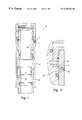
- FIGS. 1 to 5illustrate the use of a rupture disk 12 with a prior art downhole valve 10 .
- the valve 10has a blocking member 16 that is generally spherical.
- the blocking member 16has a central passage 18 that will allow the flow of fluid through the valve.
- the blocking membercan also be rotated by linkage 20 to block the flow of fluid.
- the rupture diskis used to block port 14 .
- the rupture diskis connected to the outer frame of the valve 10 across the port 14 with threads 12 b .
- the annulus pressurewill rupture the disk, specifically, the pressure will rupture a centrally located rupture surface 12 a , best shown in FIG. 5 . Pressurized annulus fluid will then flood into chamber 22 and act against surface 24 of sliding member 26 .
- the sliding member 26will be forced downward within the valve 10 .
- the sliding member 26is coupled to the blocking member 16 by linkage 20 so that the downward motion of the sliding member 26 rotates the blocking member 16 into a blocking position.
- This tool configured for use with a rupture diskis susceptible to the same errors as plague all prior art rupture disks, an inability to precisely control the depth of actuation.
- the present inventionprovides both an improved method of actuating a downhole tool with a rupture disk as well as an improved rupture disk apparatus.
- the improved rupture diskincludes a casing with a central flow passage and a rupture portion across the flow passage.
- the rupture diskalso has a destructive material nested adjacent to the rupture portion.
- the destructive materialcan be either an explosive or a corrosive chemical.
- a rupture eventcan be initiated by the transmission of an acoustic signal down the fluid column in the well's annulus. The transmission could also be transmitted down the fluid column within the tool string. The signal is received by a receiver that generates a triggering signal that detonates the explosive destroying the rupture element. If a corrosive is released instead, it may simply weaken the rupture portion enough that the annulus pressure will burst the rupture portion.
- the receivercan be a simple piezoelectric crystal with a range of vibrational frequencies. When a suitable vibrational acoustic signal is received by the crystal, it will produce a current which can be used to trigger the rupture event. This embodiment likewise would allow for the sequential firing of multiple ruptured disks.
- several crystalscan be coupled to separate rupture disks, wherein each crystal has a different resonant frequency. This allows separate addressing of various rupture disks and allow for the sequential firing of multiple rupture disks.
- the receivercan be a battery powered acoustic receiver coupled to a microprocessor. In this embodiment the microprocessor can be programmed to recognize many different acoustical signals and address any of the multiple number of ruptured disks with triggering signals.
- the method and apparatusis an improvement over the prior art in that the use of an acoustic signal to initiate the rupture event enables the user to ensure that the downhole tool has been properly located before actuation.
- FIGS. 1 to 4illustrate the use of a rupture disk to control the motion of a downhole valve
- FIG. 5is a sectional view across the body of a prior art rupture valve
- FIG. 6is a sectional view across the body of a rupture valve embodying the present invention.
- FIG. 7is a sectional view across the rupture disk of FIG. 6 after a rupture event.
- FIGS. 8 and 9are block diagrams of alternate embodiments of the apparatus used to remotely trigger a rupture event.
- FIGS. 6 and 7illustrate an improved rupture disk 100 embodying the present invention.
- the rupture disk 100includes a generally cylindrical casing 102 .
- the casingcan include threading 104 on its outer surface suitable for coupling the rupture disk 100 across a port on a downhole tool.
- the rupture diskcan include a seal 106 such as the o-ring illustrated.
- the casing 102defines a central passage 108 .
- the passagecan have any suitable diameter, but is typically between 1 ⁇ 4 inch and 1 inch.
- Across the passageis a thin shield, or rupture portion 110 .
- the rupture portionshould be of sufficient thickness or burst strength to withstand the annulus pressure.
- a destructive, or fusiable, material 112is placed adjacent to the rupture portion 110 .
- the destructive material 112can be either an explosive sufficient to blow out the rupture portion 110 or a chemical that would react with and sufficiently weaken or perforate the material of the rupture portion 110 . If a chemical reactant is used, it must be temporarily isolated from the rupture portion 110 .
- the chemical reactantmight be an acid stored in an inert pouch glued to the rupture portion 110 .
- a signalcan be transmitted through the fluid column in the well's annulus.
- the signalcan be passed down the pipe or through the adjacent earth.
- the signalcan be an acoustic pressure pulse, an electromagnetic signal, a seismic signal, or a signal from almost any other source.
- the signalis received by a receiver, or other detection means, which then issues a triggering signal to the destructive material adjacent to the rupture portion.
- FIG. 8illustrates an embodiment 120 wherein the receiver is a piezoelectric crystal 122 .
- the crystalhas a range of vibrational frequencies that produce an electric output.
- the outputis conditioned 124 to produce a triggering signal.
- the charge produced by the piezoelectric crystal 122can be stored on a capacitor until it discharges the charge through a diode and into the destructive material.
- the destructive material 112is an explosive charge
- the chargemight be sufficient to detonate the explosive.
- the chargemight be used to trigger a detonator that in turn detonates the explosive or ruptures or melts the inert storage sack holding the chemical reactant.
- This embodiment of the inventionhas the advantage of being self-contained. No external power source needs to be included, because the piezoelectric crystal translates the vibrational energy from the signal into electricity.
- An alternate system embodimentuses several piezo-electric crystals with distinguishable vibrational frequencies. This allows multiple rupture disks to be addressed separately. For example, several downhole tools might be located on a single tool string suspended from the surface. Each device might utilize a rupture disk to achieve actuation. The present invention would allow for each rupture disk to have a specific “address.” The address could be the specific signal required before a triggering signal is produced by the microprocessor. Thus, the use of a first signal would trigger only a first rupture disk. A second signal would trigger a second rupture disk. A sequential firing of rupture disks could be achieved, allowing for the sequential operation of several downhole tools.
- FIG. 9Another alternate system embodiment 130 uses a battery-powered receiver and is illustrated by FIG. 9 .
- the battery 134is coupled to the receiver 132 .
- the receiver 132may be capable of receiving multiple signals.
- the signalmight be a timed pulse or a series of several pulses.
- the signalcan be analyzed by a microprocessor 136 which then produces a triggering signal conveyed to the destructive material 112 .
- the added advantage of this alternate systemis that multiple ruptured disks could be addressed with distinguishable acoustic signals. For example, several downhole tools might be located on a single tool string suspended from the surface. Each device might utilize a rupture disk to achieve actuation.
- each rupture diskwould be programmed with a specific “address.”
- the addresscould be the specific acoustic signal required before a triggering signal is produced by the microprocessor 136 .
- the use of a first acoustical signalwould trigger only a first rupture disk.
- the second acoustical signalwould trigger a second rupture disk.
- a sequential filing of rupture diskswould be achieved, allowing for the sequential operation of several downhole tools.
Landscapes
- Engineering & Computer Science (AREA)
- Life Sciences & Earth Sciences (AREA)
- Geology (AREA)
- Mining & Mineral Resources (AREA)
- Physics & Mathematics (AREA)
- Environmental & Geological Engineering (AREA)
- Fluid Mechanics (AREA)
- General Life Sciences & Earth Sciences (AREA)
- Geochemistry & Mineralogy (AREA)
- Remote Sensing (AREA)
- Geophysics (AREA)
- Geophysics And Detection Of Objects (AREA)
Abstract
Description
1. Technical Field
The present invention relates generally to rupture disks used to actuate tools used in subterranean wells and, specifically relates to a rupture disk that can be ruptured upon receipt of a predetermined triggering signal from a remote source. The triggering signal can be an acoustic pressure pulse, an electromagnetic signal, a seismic signal, or from any other suitable source.
2. Description of the Related Art
Many downhole tools are dynamic. In other words, their movement or configuration can be altered once the tool has been lowered into the well as part of a tool string. Changing the configuration of a downhole tool is typically accomplished through the use of control lines that supply hydraulic pressure to the tool. The hydraulic pressure, when applied, can be used to push elements within the tool to specific locations or to perform specific functions.
A downhole tool has a specific function and typically must be actuated when it is adjacent to a specific formation strata. However, the use of control lines to actuate the tool implicates a number of additional design problems. For example, as the length of the control line increases, so does the hydraulic head experienced on the tool simply from the weight of the hydraulic fluid in the line. Further, the use of control lines increases the cost of the job and the risk of equipment failure.
Rupture disks offer another method of actuating downhole tools. A rupture disk is a plug used to block ports in the tool. Prior art rupture disks are designed to fail when subjected to a predetermined pressure. Once the disk fails, the port is exposed to pressurized fluid from outside the tool, which can flood compartments within the tool. The fluid pressure is then used to actuate the tool, instead of control line pressure. The pressure of the fluid is a function of the well depth. In other words, the increase in pressure is proportional to the depth of the well. The depth of the strata of interest is generally known. Therefore, the rupture disk chosen for a particular tool is sized to fail at the pressure associated with the depth of the specific strata.
FIGS. 1 to5 illustrate the use of arupture disk 12 with a priorart downhole valve 10. Thevalve 10 has a blockingmember 16 that is generally spherical. The blockingmember 16 has acentral passage 18 that will allow the flow of fluid through the valve. The blocking member can also be rotated bylinkage 20 to block the flow of fluid. The rupture disk is used to blockport 14. The rupture disk is connected to the outer frame of thevalve 10 across theport 14 with threads12b. When the valve is lowered to a sufficient depth, the annulus pressure will rupture the disk, specifically, the pressure will rupture a centrally located rupture surface12a, best shown in FIG.5. Pressurized annulus fluid will then flood intochamber 22 and act againstsurface 24 of slidingmember 26. Aschamber 22 fills with fluid, the slidingmember 26 will be forced downward within thevalve 10. The slidingmember 26 is coupled to the blockingmember 16 bylinkage 20 so that the downward motion of the slidingmember 26 rotates the blockingmember 16 into a blocking position. This tool configured for use with a rupture disk is susceptible to the same errors as plague all prior art rupture disks, an inability to precisely control the depth of actuation.
A need exists for a system of controlling the precise depth at which a rupture disk ruptures. Such a system would allow a tool to be placed at a correct depth before actuation. Further, such a system would include both an improved method for controlling the rupture event as well as an improved rupture disk apparatus.
The present invention provides both an improved method of actuating a downhole tool with a rupture disk as well as an improved rupture disk apparatus. The improved rupture disk includes a casing with a central flow passage and a rupture portion across the flow passage. The rupture disk also has a destructive material nested adjacent to the rupture portion. The destructive material can be either an explosive or a corrosive chemical. A rupture event can be initiated by the transmission of an acoustic signal down the fluid column in the well's annulus. The transmission could also be transmitted down the fluid column within the tool string. The signal is received by a receiver that generates a triggering signal that detonates the explosive destroying the rupture element. If a corrosive is released instead, it may simply weaken the rupture portion enough that the annulus pressure will burst the rupture portion.
The receiver can be a simple piezoelectric crystal with a range of vibrational frequencies. When a suitable vibrational acoustic signal is received by the crystal, it will produce a current which can be used to trigger the rupture event. This embodiment likewise would allow for the sequential firing of multiple ruptured disks. In one embodiment, several crystals can be coupled to separate rupture disks, wherein each crystal has a different resonant frequency. This allows separate addressing of various rupture disks and allow for the sequential firing of multiple rupture disks. Alternatively, the receiver can be a battery powered acoustic receiver coupled to a microprocessor. In this embodiment the microprocessor can be programmed to recognize many different acoustical signals and address any of the multiple number of ruptured disks with triggering signals. The method and apparatus is an improvement over the prior art in that the use of an acoustic signal to initiate the rupture event enables the user to ensure that the downhole tool has been properly located before actuation.
The novel features believed characteristic of the invention are set forth in the appended claims. The invention itself however, as well as a preferred mode of use, further objects and advantages thereof, will best be understood by reference to the following detailed description of an illustrative embodiment when read in conjunction with the accompanying drawings, wherein:
FIGS. 1 to4 illustrate the use of a rupture disk to control the motion of a downhole valve;
FIG. 5 is a sectional view across the body of a prior art rupture valve;
FIG. 6 is a sectional view across the body of a rupture valve embodying the present invention;
FIG. 7 is a sectional view across the rupture disk of FIG. 6 after a rupture event; and
FIGS. 8 and 9 are block diagrams of alternate embodiments of the apparatus used to remotely trigger a rupture event.
FIGS. 6 and 7 illustrate an improvedrupture disk 100 embodying the present invention. Therupture disk 100 includes a generallycylindrical casing 102. The casing can include threading104 on its outer surface suitable for coupling therupture disk 100 across a port on a downhole tool. Further, the rupture disk can include aseal 106 such as the o-ring illustrated. Thecasing 102 defines acentral passage 108. The passage can have any suitable diameter, but is typically between ¼ inch and 1 inch. Across the passage is a thin shield, orrupture portion 110. Unlike prior art rupture disk designs, the rupture portion should be of sufficient thickness or burst strength to withstand the annulus pressure.
A destructive, or fusiable,material 112 is placed adjacent to therupture portion 110. Thedestructive material 112 can be either an explosive sufficient to blow out therupture portion 110 or a chemical that would react with and sufficiently weaken or perforate the material of therupture portion 110. If a chemical reactant is used, it must be temporarily isolated from therupture portion 110. For example, the chemical reactant might be an acid stored in an inert pouch glued to therupture portion 110.
To trigger the rupture event, a signal can be transmitted through the fluid column in the well's annulus. Alternatively, the signal can be passed down the pipe or through the adjacent earth. The signal can be an acoustic pressure pulse, an electromagnetic signal, a seismic signal, or a signal from almost any other source. The signal is received by a receiver, or other detection means, which then issues a triggering signal to the destructive material adjacent to the rupture portion. FIG. 8 illustrates anembodiment 120 wherein the receiver is apiezoelectric crystal 122. The crystal has a range of vibrational frequencies that produce an electric output. The output is conditioned124 to produce a triggering signal. For example, the charge produced by thepiezoelectric crystal 122 can be stored on a capacitor until it discharges the charge through a diode and into the destructive material. If thedestructive material 112 is an explosive charge, the charge might be sufficient to detonate the explosive. Alternatively, the charge might be used to trigger a detonator that in turn detonates the explosive or ruptures or melts the inert storage sack holding the chemical reactant. This embodiment of the invention has the advantage of being self-contained. No external power source needs to be included, because the piezoelectric crystal translates the vibrational energy from the signal into electricity.
An alternate system embodiment uses several piezo-electric crystals with distinguishable vibrational frequencies. This allows multiple rupture disks to be addressed separately. For example, several downhole tools might be located on a single tool string suspended from the surface. Each device might utilize a rupture disk to achieve actuation. The present invention would allow for each rupture disk to have a specific “address.” The address could be the specific signal required before a triggering signal is produced by the microprocessor. Thus, the use of a first signal would trigger only a first rupture disk. A second signal would trigger a second rupture disk. A sequential firing of rupture disks could be achieved, allowing for the sequential operation of several downhole tools.
Anotheralternate system embodiment 130 uses a battery-powered receiver and is illustrated by FIG.9. Thebattery 134 is coupled to thereceiver 132. Thereceiver 132 may be capable of receiving multiple signals. For example, the signal might be a timed pulse or a series of several pulses. The signal can be analyzed by amicroprocessor 136 which then produces a triggering signal conveyed to thedestructive material 112. The added advantage of this alternate system is that multiple ruptured disks could be addressed with distinguishable acoustic signals. For example, several downhole tools might be located on a single tool string suspended from the surface. Each device might utilize a rupture disk to achieve actuation. The present invention would allow for each rupture disk to be programmed with a specific “address.” The address could be the specific acoustic signal required before a triggering signal is produced by themicroprocessor 136. Thus, the use of a first acoustical signal would trigger only a first rupture disk. The second acoustical signal would trigger a second rupture disk. A sequential filing of rupture disks would be achieved, allowing for the sequential operation of several downhole tools.
The description of the present invention has been presented for purposes of illustration and description, but is not limited to be exhaustive or limited to the invention in the form disclosed. Many modifications and variations will be apparent to those of ordinary skill in the art. The embodiment was chosen and described in order to best explain the principles of the invention the practical application to enable others of ordinary skill in the art to understand the invention for various embodiments with various modifications as are suited to the particular use contemplated. For example, while the term “acoustic” has been used to describe the actuation signal, an electromagnetic signal, seismic signal, or any other suitable signal could also be used. Further, while the description describes the transmission of the signal through the annulus fluid column, it could also be transmitted down the internal fluid column within the tool string or through the metal of the tool string, or through the earth adjacent to the well.
Claims (20)
1. A method of triggering a rupture event for at least one rupture disk coupled to a downhole tool on a string in a well, the method comprising:
(a) transmitting a signal to a receiver in the well wherein the receiver is coupled to the at least one rupture disk, wherein said signal is acoustic, electromagnetic, or seismic;
(b) triggering the rupture event in response to the signal.
2. The method ofclaim 1 wherein step (a) comprises transmitting the signal through a fluid column.
3. The method ofclaim 1 wherein step (a) comprises transmitting the signal through the string.
4. The method ofclaim 1 wherein step (a) comprises transmitting the signal through the earth adjacent to the well.
5. The method ofclaim 1 wherein step (a) comprises transmitting an acoustic signal.
6. The method ofclaim 1 wherein step (a) comprises transmitting an electro-magnetic signal.
7. The method ofclaim 1 wherein step (a) comprises transmitting a seismic signal.
8. The method ofclaim 1 wherein step (b) further comprises triggering the rupture event with an output from a piezoelectric crystal.
9. The method ofclaim 1 wherein step (b) further comprises producing a triggering signal to a first rupture disk in response to a first signal.
10. The method ofclaim 1 wherein step (b) further comprises exploding a destructive material adjacent to a rupture portion of the rupture disk.
11. The method ofclaim 1 wherein step (b) further comprises releasing a chemical reactant adjacent to a rupture portion of the rupture disk.
12. The method ofclaim 1 wherein step (a) comprises transmitting a signal to a non-battery powered receiver.
13. A method of triggering rupture events for rupture disks coupled to downhole tools on a tool string in a well, the method comprising:
transmitting a signal to a plurality of receivers in the well wherein ones of said plurality of receivers are coupled to respective rupture disks;
triggering separate rupture events in response to the signal; wherein ones of said plurality of receivers are individually addressable by said signal.
14. The method ofclaim 13 , wherein said plurality of receivers are piezoelectric crystals having different resonant frequencies.
15. The method ofclaim 13 , wherein said plurality of receivers are coupled to respective microprocessors programmed to recognize different signals.
16. A method of triggering a rupture event, comprising the steps of:
attaching a downhole tool containing a rupture disk to a tool string;
running said downhole tool and said tool string into a well;
transmitting a signal to a receiver in the well wherein the receiver is coupled to the rupture disk;
triggering the rupture event in response to the signal.
17. The method ofclaim 16 , wherein said plurality of receivers are piezoelectric crystals having different resonant frequencies.
18. The method ofclaim 16 , wherein said plurality of receivers are coupled to respective microprocessors programmed to recognize different signals.
19. The method ofclaim 16 , wherein said triggering step explodes a destructive material adjacent a rupture portion of the rupture disk.
20. The method ofclaim 16 , wherein said triggering step releases a chemical reactant adjacent a rupture portion of the rupture disk.
Priority Applications (1)
| Application Number | Priority Date | Filing Date | Title |
|---|---|---|---|
| US09/203,800US6450263B1 (en) | 1998-12-01 | 1998-12-01 | Remotely actuated rupture disk |
Applications Claiming Priority (1)
| Application Number | Priority Date | Filing Date | Title |
|---|---|---|---|
| US09/203,800US6450263B1 (en) | 1998-12-01 | 1998-12-01 | Remotely actuated rupture disk |
Publications (1)
| Publication Number | Publication Date |
|---|---|
| US6450263B1true US6450263B1 (en) | 2002-09-17 |
Family
ID=22755374
Family Applications (1)
| Application Number | Title | Priority Date | Filing Date |
|---|---|---|---|
| US09/203,800Expired - LifetimeUS6450263B1 (en) | 1998-12-01 | 1998-12-01 | Remotely actuated rupture disk |
Country Status (1)
| Country | Link |
|---|---|
| US (1) | US6450263B1 (en) |
Cited By (80)
| Publication number | Priority date | Publication date | Assignee | Title |
|---|---|---|---|---|
| US6675898B2 (en)* | 2001-03-29 | 2004-01-13 | Hunting Energy Services, Lp | Apparatus for preventing critical annular pressure buildup |
| US20040020832A1 (en)* | 2002-01-25 | 2004-02-05 | Richards William Mark | Sand control screen assembly and treatment method using the same |
| US20040035578A1 (en)* | 2002-08-26 | 2004-02-26 | Ross Colby M. | Fluid flow control device and method for use of same |
| US6702019B2 (en)* | 2001-10-22 | 2004-03-09 | Halliburton Energy Services, Inc. | Apparatus and method for progressively treating an interval of a wellbore |
| US6702018B2 (en) | 2001-03-06 | 2004-03-09 | Halliburton Energy Services, Inc. | Apparatus and method for gravel packing an interval of a wellbore |
| US20040055749A1 (en)* | 2002-09-23 | 2004-03-25 | Lonnes Steven B. | Remote intervention logic valving method and apparatus |
| US20040074641A1 (en)* | 2002-10-17 | 2004-04-22 | Hejl David A. | Gravel packing apparatus having an integrated joint connection and method for use of same |
| US20040149435A1 (en)* | 2003-02-05 | 2004-08-05 | Henderson William D. | Well screen assembly and system with controllable variable flow area and method of using same for oil well fluid production |
| US6772837B2 (en)* | 2001-10-22 | 2004-08-10 | Halliburton Energy Services, Inc. | Screen assembly having diverter members and method for progressively treating an interval of a welibore |
| US6776238B2 (en) | 2002-04-09 | 2004-08-17 | Halliburton Energy Services, Inc. | Single trip method for selectively fracture packing multiple formations traversed by a wellbore |
| US20040173352A1 (en)* | 2000-07-13 | 2004-09-09 | Mullen Bryon David | Gravel packing apparatus having an integrated sensor and method for use of same |
| US6789624B2 (en) | 2002-05-31 | 2004-09-14 | Halliburton Energy Services, Inc. | Apparatus and method for gravel packing an interval of a wellbore |
| US20050016730A1 (en)* | 2003-07-21 | 2005-01-27 | Mcmechan David E. | Apparatus and method for monitoring a treatment process in a production interval |
| US20050082061A1 (en)* | 2001-08-14 | 2005-04-21 | Nguyen Philip D. | Methods and apparatus for completing wells |
| US20050274528A1 (en)* | 2004-06-10 | 2005-12-15 | Schlumberger Technology Corporation | Valve Within a Control Line |
| US20060037752A1 (en)* | 2004-08-20 | 2006-02-23 | Penno Andrew D | Rat hole bypass for gravel packing assembly |
| US20060042795A1 (en)* | 2004-08-24 | 2006-03-02 | Richards William M | Sand control screen assembly having fluid loss control capability and method for use of same |
| US20070062690A1 (en)* | 2005-09-16 | 2007-03-22 | Witcher Harold L | Packer washout assembly |
| US20070204998A1 (en)* | 2006-03-03 | 2007-09-06 | Schlumberger Technology Corporation | Pressure Protection for a Control Chamber of a Well Tool |
| US20070209802A1 (en)* | 2006-03-07 | 2007-09-13 | Yang Xu | Downhole trigger device |
| US20070251698A1 (en)* | 2006-04-28 | 2007-11-01 | Weatherford/Lamb, Inc. | Temporary well zone isolation |
| US20100175867A1 (en)* | 2009-01-14 | 2010-07-15 | Halliburton Energy Services, Inc. | Well Tools Incorporating Valves Operable by Low Electrical Power Input |
| US20100236790A1 (en)* | 2008-09-09 | 2010-09-23 | Halliburton Energy Services, Inc. | Control of well tools utilizing downhole pumps |
| US20100237698A1 (en)* | 2008-09-09 | 2010-09-23 | Halliburton Energy Services, Inc. | Sneak path eliminator for diode multiplexed control of downhole well tools |
| US20110056679A1 (en)* | 2009-09-09 | 2011-03-10 | Schlumberger Technology Corporation | System and method for controlling actuation of downhole tools |
| US20110168403A1 (en)* | 2010-01-08 | 2011-07-14 | Schlumberger Technology Corporation | Wirelessly actuated hydrostatic set module |
| US20110174504A1 (en)* | 2010-01-15 | 2011-07-21 | Halliburton Energy Services, Inc. | Well tools operable via thermal expansion resulting from reactive materials |
| US20110210609A1 (en)* | 2008-09-09 | 2011-09-01 | Smithson Mitchell C | Sneak path eliminator for diode multiplexed control of downhole well tools |
| US20110214883A1 (en)* | 2010-03-04 | 2011-09-08 | Schlumberger Technology Corporation | Large bore completions systems and method |
| US20120024536A1 (en)* | 2010-07-29 | 2012-02-02 | Vetco Gray Inc. | Wellhead tree pressure limiting device |
| US20120168173A1 (en)* | 2010-12-29 | 2012-07-05 | Vetco Gray Inc. | Wellhead tree pressure compensating device |
| EP2597491A1 (en) | 2011-11-24 | 2013-05-29 | Services Pétroliers Schlumberger | Surface communication system for communication with downhole wireless modem prior to deployment |
| US20130153236A1 (en)* | 2011-12-20 | 2013-06-20 | Baker Hughes Incorporated | Subterranean Tool Actuation Using a Controlled Electrolytic Material Trigger |
| US8476786B2 (en) | 2010-06-21 | 2013-07-02 | Halliburton Energy Services, Inc. | Systems and methods for isolating current flow to well loads |
| US8616290B2 (en) | 2010-04-29 | 2013-12-31 | Halliburton Energy Services, Inc. | Method and apparatus for controlling fluid flow using movable flow diverter assembly |
| US8657017B2 (en) | 2009-08-18 | 2014-02-25 | Halliburton Energy Services, Inc. | Method and apparatus for autonomous downhole fluid selection with pathway dependent resistance system |
| WO2014035420A1 (en) | 2012-08-31 | 2014-03-06 | Halliburton Energy Services, Inc. | Electronic rupture discs for interventionless barrier plug |
| US20140218207A1 (en)* | 2013-02-04 | 2014-08-07 | Halliburton Energy Services, Inc. | Method and apparatus for remotely controlling downhole tools using untethered mobile devices |
| US8967272B2 (en) | 2013-02-21 | 2015-03-03 | Hunting Energy Services, Inc. | Annular pressure relief system |
| US8973657B2 (en) | 2010-12-07 | 2015-03-10 | Halliburton Energy Services, Inc. | Gas generator for pressurizing downhole samples |
| US8991506B2 (en) | 2011-10-31 | 2015-03-31 | Halliburton Energy Services, Inc. | Autonomous fluid control device having a movable valve plate for downhole fluid selection |
| US9127526B2 (en) | 2012-12-03 | 2015-09-08 | Halliburton Energy Services, Inc. | Fast pressure protection system and method |
| US9169705B2 (en) | 2012-10-25 | 2015-10-27 | Halliburton Energy Services, Inc. | Pressure relief-assisted packer |
| US9260952B2 (en) | 2009-08-18 | 2016-02-16 | Halliburton Energy Services, Inc. | Method and apparatus for controlling fluid flow in an autonomous valve using a sticky switch |
| US9284817B2 (en) | 2013-03-14 | 2016-03-15 | Halliburton Energy Services, Inc. | Dual magnetic sensor actuation assembly |
| US9291032B2 (en) | 2011-10-31 | 2016-03-22 | Halliburton Energy Services, Inc. | Autonomous fluid control device having a reciprocating valve for downhole fluid selection |
| US9366134B2 (en) | 2013-03-12 | 2016-06-14 | Halliburton Energy Services, Inc. | Wellbore servicing tools, systems and methods utilizing near-field communication |
| US9404349B2 (en) | 2012-10-22 | 2016-08-02 | Halliburton Energy Services, Inc. | Autonomous fluid control system having a fluid diode |
| US9441437B2 (en) | 2013-05-16 | 2016-09-13 | Halliburton Energy Services, Inc. | Electronic rupture discs for interventionless barrier plug |
| US9587486B2 (en) | 2013-02-28 | 2017-03-07 | Halliburton Energy Services, Inc. | Method and apparatus for magnetic pulse signature actuation |
| US9695654B2 (en) | 2012-12-03 | 2017-07-04 | Halliburton Energy Services, Inc. | Wellhead flowback control system and method |
| US20170234091A1 (en)* | 2016-02-11 | 2017-08-17 | Baker Hughes Incorporated | Removable Control Line Barrier |
| US9752414B2 (en) | 2013-05-31 | 2017-09-05 | Halliburton Energy Services, Inc. | Wellbore servicing tools, systems and methods utilizing downhole wireless switches |
| US20180051535A1 (en)* | 2016-08-19 | 2018-02-22 | Schlumberger Technology Corporation | Systems and techniques for controlling and monitoring downhole operations in a well |
| US10066467B2 (en) | 2015-03-12 | 2018-09-04 | Ncs Multistage Inc. | Electrically actuated downhole flow control apparatus |
| US10167711B2 (en)* | 2014-02-04 | 2019-01-01 | Interra Energy Services Ltd. | Pressure activated completion tools and methods of use |
| WO2019005961A1 (en)* | 2017-06-27 | 2019-01-03 | Innovex Downhole Solutions, Inc. | Float sub with pressure-frangible plug |
| WO2020131076A1 (en)* | 2018-12-20 | 2020-06-25 | Halliburtion Energy Services, Inc. | Buoyancy assist tool |
| US10808523B2 (en) | 2014-11-25 | 2020-10-20 | Halliburton Energy Services, Inc. | Wireless activation of wellbore tools |
| US10833728B2 (en) | 2017-08-01 | 2020-11-10 | Baker Hughes, A Ge Company, Llc | Use of crosstalk between adjacent cables for wireless communication |
| US10907471B2 (en) | 2013-05-31 | 2021-02-02 | Halliburton Energy Services, Inc. | Wireless activation of wellbore tools |
| US10989013B1 (en) | 2019-11-20 | 2021-04-27 | Halliburton Energy Services, Inc. | Buoyancy assist tool with center diaphragm debris barrier |
| WO2021080624A1 (en)* | 2019-10-25 | 2021-04-29 | Halliburton Energy Services, Inc. | Buoyancy assist tool with overlapping membranes |
| US10995583B1 (en) | 2019-10-31 | 2021-05-04 | Halliburton Energy Services, Inc. | Buoyancy assist tool with debris barrier |
| US11067106B2 (en) | 2018-05-25 | 2021-07-20 | Schlumberger Technology Corporation | System for implementing redundancy in hydraulic circuits and actuating multi-cycle hydraulic tools |
| US11105166B2 (en) | 2019-08-27 | 2021-08-31 | Halliburton Energy Services, Inc. | Buoyancy assist tool with floating piston |
| US11142994B2 (en) | 2020-02-19 | 2021-10-12 | Halliburton Energy Services, Inc. | Buoyancy assist tool with annular cavity and piston |
| US11199071B2 (en) | 2017-11-20 | 2021-12-14 | Halliburton Energy Services, Inc. | Full bore buoyancy assisted casing system |
| US11230905B2 (en) | 2019-12-03 | 2022-01-25 | Halliburton Energy Services, Inc. | Buoyancy assist tool with waffle debris barrier |
| US11255155B2 (en) | 2019-05-09 | 2022-02-22 | Halliburton Energy Services, Inc. | Downhole apparatus with removable plugs |
| US11293261B2 (en) | 2018-12-21 | 2022-04-05 | Halliburton Energy Services, Inc. | Buoyancy assist tool |
| US11346171B2 (en) | 2018-12-05 | 2022-05-31 | Halliburton Energy Services, Inc. | Downhole apparatus |
| US11359454B2 (en) | 2020-06-02 | 2022-06-14 | Halliburton Energy Services, Inc. | Buoyancy assist tool with annular cavity and piston |
| US11492867B2 (en) | 2019-04-16 | 2022-11-08 | Halliburton Energy Services, Inc. | Downhole apparatus with degradable plugs |
| US11499395B2 (en) | 2019-08-26 | 2022-11-15 | Halliburton Energy Services, Inc. | Flapper disk for buoyancy assisted casing equipment |
| US11603736B2 (en) | 2019-04-15 | 2023-03-14 | Halliburton Energy Services, Inc. | Buoyancy assist tool with degradable nose |
| US11808110B2 (en) | 2019-04-24 | 2023-11-07 | Schlumberger Technology Corporation | System and methodology for actuating a downhole device |
| GB2620838A (en)* | 2022-06-10 | 2024-01-24 | Tco As | Asymmetric bearing ring |
| US12371957B2 (en) | 2021-04-06 | 2025-07-29 | Schlumberger Technology Corporation | Trigger system for a downhole tool |
| US12442276B2 (en) | 2022-03-23 | 2025-10-14 | Schlumberger Technology Corporation | Redundant trigger system |
Citations (21)
| Publication number | Priority date | Publication date | Assignee | Title |
|---|---|---|---|---|
| US3737845A (en) | 1971-02-17 | 1973-06-05 | H Maroney | Subsurface well control apparatus and method |
| US3906435A (en) | 1971-02-08 | 1975-09-16 | American Petroscience Corp | Oil well telemetering system with torsional transducer |
| US4609005A (en)* | 1985-07-19 | 1986-09-02 | Schlumberger Technology Corporation | Tubing isolation disc valve |
| US4862426A (en) | 1987-12-08 | 1989-08-29 | Cameron Iron Works Usa, Inc. | Method and apparatus for operating equipment in a remote location |
| US4908804A (en) | 1983-03-21 | 1990-03-13 | Develco, Inc. | Combinatorial coded telemetry in MWD |
| US4911242A (en)* | 1988-04-06 | 1990-03-27 | Schlumberger Technology Corporation | Pressure-controlled well tester operated by one or more selected actuating pressures |
| US4986350A (en) | 1989-02-09 | 1991-01-22 | Institut Francais Du Petrole | Device for the seismic monitoring of an underground deposit |
| US5067114A (en) | 1983-03-21 | 1991-11-19 | Develco, Inc. | Correlation for combinational coded telemetry |
| US5103906A (en)* | 1990-10-24 | 1992-04-14 | Halliburton Company | Hydraulic timer for downhole tool |
| US5146983A (en)* | 1991-03-15 | 1992-09-15 | Schlumberger Technology Corporation | Hydrostatic setting tool including a selectively operable apparatus initially blocking an orifice disposed between two chambers and opening in response to a signal |
| US5166908A (en) | 1990-07-16 | 1992-11-24 | Atlantic Richfield Company | Piezoelectric transducer for high speed data transmission and method of operation |
| US5272680A (en) | 1990-01-09 | 1993-12-21 | Baker Hughes Incorporated | Method of decoding MWD signals using annular pressure signals |
| US5293937A (en) | 1992-11-13 | 1994-03-15 | Halliburton Company | Acoustic system and method for performing operations in a well |
| US5343963A (en) | 1990-07-09 | 1994-09-06 | Bouldin Brett W | Method and apparatus for providing controlled force transference to a wellbore tool |
| US5363094A (en) | 1991-12-16 | 1994-11-08 | Institut Francais Du Petrole | Stationary system for the active and/or passive monitoring of an underground deposit |
| US5535177A (en) | 1994-08-17 | 1996-07-09 | Halliburton Company | MWD surface signal detector having enhanced acoustic detection means |
| US5546359A (en) | 1994-03-16 | 1996-08-13 | Aker Engineering As | Method and transmitter/receiver for transferring signals through a medium in pipes and hoses |
| US5579283A (en) | 1990-07-09 | 1996-11-26 | Baker Hughes Incorporated | Method and apparatus for communicating coded messages in a wellbore |
| US5611401A (en)* | 1995-07-11 | 1997-03-18 | Baker Hughes Incorporated | One-trip conveying method for packer/plug and perforating gun |
| US5649597A (en)* | 1995-07-14 | 1997-07-22 | Halliburton Company | Differential pressure test/bypass valve and method for using the same |
| US5696733A (en) | 1996-10-30 | 1997-12-09 | Western Atlas International Inc. | Method for verifying the location of an array of sensors |
- 1998
- 1998-12-01USUS09/203,800patent/US6450263B1/ennot_activeExpired - Lifetime
Patent Citations (21)
| Publication number | Priority date | Publication date | Assignee | Title |
|---|---|---|---|---|
| US3906435A (en) | 1971-02-08 | 1975-09-16 | American Petroscience Corp | Oil well telemetering system with torsional transducer |
| US3737845A (en) | 1971-02-17 | 1973-06-05 | H Maroney | Subsurface well control apparatus and method |
| US4908804A (en) | 1983-03-21 | 1990-03-13 | Develco, Inc. | Combinatorial coded telemetry in MWD |
| US5067114A (en) | 1983-03-21 | 1991-11-19 | Develco, Inc. | Correlation for combinational coded telemetry |
| US4609005A (en)* | 1985-07-19 | 1986-09-02 | Schlumberger Technology Corporation | Tubing isolation disc valve |
| US4862426A (en) | 1987-12-08 | 1989-08-29 | Cameron Iron Works Usa, Inc. | Method and apparatus for operating equipment in a remote location |
| US4911242A (en)* | 1988-04-06 | 1990-03-27 | Schlumberger Technology Corporation | Pressure-controlled well tester operated by one or more selected actuating pressures |
| US4986350A (en) | 1989-02-09 | 1991-01-22 | Institut Francais Du Petrole | Device for the seismic monitoring of an underground deposit |
| US5272680A (en) | 1990-01-09 | 1993-12-21 | Baker Hughes Incorporated | Method of decoding MWD signals using annular pressure signals |
| US5579283A (en) | 1990-07-09 | 1996-11-26 | Baker Hughes Incorporated | Method and apparatus for communicating coded messages in a wellbore |
| US5343963A (en) | 1990-07-09 | 1994-09-06 | Bouldin Brett W | Method and apparatus for providing controlled force transference to a wellbore tool |
| US5166908A (en) | 1990-07-16 | 1992-11-24 | Atlantic Richfield Company | Piezoelectric transducer for high speed data transmission and method of operation |
| US5103906A (en)* | 1990-10-24 | 1992-04-14 | Halliburton Company | Hydraulic timer for downhole tool |
| US5146983A (en)* | 1991-03-15 | 1992-09-15 | Schlumberger Technology Corporation | Hydrostatic setting tool including a selectively operable apparatus initially blocking an orifice disposed between two chambers and opening in response to a signal |
| US5363094A (en) | 1991-12-16 | 1994-11-08 | Institut Francais Du Petrole | Stationary system for the active and/or passive monitoring of an underground deposit |
| US5293937A (en) | 1992-11-13 | 1994-03-15 | Halliburton Company | Acoustic system and method for performing operations in a well |
| US5546359A (en) | 1994-03-16 | 1996-08-13 | Aker Engineering As | Method and transmitter/receiver for transferring signals through a medium in pipes and hoses |
| US5535177A (en) | 1994-08-17 | 1996-07-09 | Halliburton Company | MWD surface signal detector having enhanced acoustic detection means |
| US5611401A (en)* | 1995-07-11 | 1997-03-18 | Baker Hughes Incorporated | One-trip conveying method for packer/plug and perforating gun |
| US5649597A (en)* | 1995-07-14 | 1997-07-22 | Halliburton Company | Differential pressure test/bypass valve and method for using the same |
| US5696733A (en) | 1996-10-30 | 1997-12-09 | Western Atlas International Inc. | Method for verifying the location of an array of sensors |
Cited By (138)
| Publication number | Priority date | Publication date | Assignee | Title |
|---|---|---|---|---|
| US7100690B2 (en) | 2000-07-13 | 2006-09-05 | Halliburton Energy Services, Inc. | Gravel packing apparatus having an integrated sensor and method for use of same |
| US20040173352A1 (en)* | 2000-07-13 | 2004-09-09 | Mullen Bryon David | Gravel packing apparatus having an integrated sensor and method for use of same |
| US6932157B2 (en) | 2001-03-06 | 2005-08-23 | Halliburton Energy Services, Inc. | Apparatus and method for treating an interval of a wellbore |
| US20050103494A1 (en)* | 2001-03-06 | 2005-05-19 | Mcgregor Ronald W. | Apparatus and method for treating an interval of a wellbore |
| US7243724B2 (en) | 2001-03-06 | 2007-07-17 | Halliburton Energy Services, Inc. | Apparatus and method for treating an interval of a wellbore |
| US6702018B2 (en) | 2001-03-06 | 2004-03-09 | Halliburton Energy Services, Inc. | Apparatus and method for gravel packing an interval of a wellbore |
| US20040221988A1 (en)* | 2001-03-06 | 2004-11-11 | Mcgregor Ronald W. | Apparatus and method for treating an interval of a wellbore |
| US6675898B2 (en)* | 2001-03-29 | 2004-01-13 | Hunting Energy Services, Lp | Apparatus for preventing critical annular pressure buildup |
| US7100691B2 (en) | 2001-08-14 | 2006-09-05 | Halliburton Energy Services, Inc. | Methods and apparatus for completing wells |
| US20050082061A1 (en)* | 2001-08-14 | 2005-04-21 | Nguyen Philip D. | Methods and apparatus for completing wells |
| US6702019B2 (en)* | 2001-10-22 | 2004-03-09 | Halliburton Energy Services, Inc. | Apparatus and method for progressively treating an interval of a wellbore |
| US6772837B2 (en)* | 2001-10-22 | 2004-08-10 | Halliburton Energy Services, Inc. | Screen assembly having diverter members and method for progressively treating an interval of a welibore |
| US7096945B2 (en) | 2002-01-25 | 2006-08-29 | Halliburton Energy Services, Inc. | Sand control screen assembly and treatment method using the same |
| US20040020832A1 (en)* | 2002-01-25 | 2004-02-05 | Richards William Mark | Sand control screen assembly and treatment method using the same |
| US6776238B2 (en) | 2002-04-09 | 2004-08-17 | Halliburton Energy Services, Inc. | Single trip method for selectively fracture packing multiple formations traversed by a wellbore |
| US6789624B2 (en) | 2002-05-31 | 2004-09-14 | Halliburton Energy Services, Inc. | Apparatus and method for gravel packing an interval of a wellbore |
| US7055598B2 (en) | 2002-08-26 | 2006-06-06 | Halliburton Energy Services, Inc. | Fluid flow control device and method for use of same |
| US20040035578A1 (en)* | 2002-08-26 | 2004-02-26 | Ross Colby M. | Fluid flow control device and method for use of same |
| US20040035591A1 (en)* | 2002-08-26 | 2004-02-26 | Echols Ralph H. | Fluid flow control device and method for use of same |
| US20060157257A1 (en)* | 2002-08-26 | 2006-07-20 | Halliburton Energy Services | Fluid flow control device and method for use of same |
| US20040055749A1 (en)* | 2002-09-23 | 2004-03-25 | Lonnes Steven B. | Remote intervention logic valving method and apparatus |
| US7516792B2 (en)* | 2002-09-23 | 2009-04-14 | Exxonmobil Upstream Research Company | Remote intervention logic valving method and apparatus |
| US20040074641A1 (en)* | 2002-10-17 | 2004-04-22 | Hejl David A. | Gravel packing apparatus having an integrated joint connection and method for use of same |
| US6814139B2 (en) | 2002-10-17 | 2004-11-09 | Halliburton Energy Services, Inc. | Gravel packing apparatus having an integrated joint connection and method for use of same |
| US6978840B2 (en) | 2003-02-05 | 2005-12-27 | Halliburton Energy Services, Inc. | Well screen assembly and system with controllable variable flow area and method of using same for oil well fluid production |
| US20040149435A1 (en)* | 2003-02-05 | 2004-08-05 | Henderson William D. | Well screen assembly and system with controllable variable flow area and method of using same for oil well fluid production |
| US7140437B2 (en) | 2003-07-21 | 2006-11-28 | Halliburton Energy Services, Inc. | Apparatus and method for monitoring a treatment process in a production interval |
| US20050016730A1 (en)* | 2003-07-21 | 2005-01-27 | Mcmechan David E. | Apparatus and method for monitoring a treatment process in a production interval |
| US7273107B2 (en)* | 2004-06-10 | 2007-09-25 | Schlumberger Technology Corporation | Valve within a control line |
| US20050274528A1 (en)* | 2004-06-10 | 2005-12-15 | Schlumberger Technology Corporation | Valve Within a Control Line |
| US20060037752A1 (en)* | 2004-08-20 | 2006-02-23 | Penno Andrew D | Rat hole bypass for gravel packing assembly |
| US7191833B2 (en) | 2004-08-24 | 2007-03-20 | Halliburton Energy Services, Inc. | Sand control screen assembly having fluid loss control capability and method for use of same |
| US20060042795A1 (en)* | 2004-08-24 | 2006-03-02 | Richards William M | Sand control screen assembly having fluid loss control capability and method for use of same |
| US20070062690A1 (en)* | 2005-09-16 | 2007-03-22 | Witcher Harold L | Packer washout assembly |
| US20070204998A1 (en)* | 2006-03-03 | 2007-09-06 | Schlumberger Technology Corporation | Pressure Protection for a Control Chamber of a Well Tool |
| US7938189B2 (en)* | 2006-03-03 | 2011-05-10 | Schlumberger Technology Corporation | Pressure protection for a control chamber of a well tool |
| US20070209802A1 (en)* | 2006-03-07 | 2007-09-13 | Yang Xu | Downhole trigger device |
| US20070251698A1 (en)* | 2006-04-28 | 2007-11-01 | Weatherford/Lamb, Inc. | Temporary well zone isolation |
| US20090151958A1 (en)* | 2006-04-28 | 2009-06-18 | Weatherford/Lamb, Inc. | Temporary well zone isolation |
| US7963340B2 (en)* | 2006-04-28 | 2011-06-21 | Weatherford/Lamb, Inc. | Method for disintegrating a barrier in a well isolation device |
| US7513311B2 (en)* | 2006-04-28 | 2009-04-07 | Weatherford/Lamb, Inc. | Temporary well zone isolation |
| US20100236790A1 (en)* | 2008-09-09 | 2010-09-23 | Halliburton Energy Services, Inc. | Control of well tools utilizing downhole pumps |
| US20100237698A1 (en)* | 2008-09-09 | 2010-09-23 | Halliburton Energy Services, Inc. | Sneak path eliminator for diode multiplexed control of downhole well tools |
| US8757278B2 (en) | 2008-09-09 | 2014-06-24 | Halliburton Energy Services, Inc. | Sneak path eliminator for diode multiplexed control of downhole well tools |
| US8590609B2 (en) | 2008-09-09 | 2013-11-26 | Halliburton Energy Services, Inc. | Sneak path eliminator for diode multiplexed control of downhole well tools |
| US20110210609A1 (en)* | 2008-09-09 | 2011-09-01 | Smithson Mitchell C | Sneak path eliminator for diode multiplexed control of downhole well tools |
| US8453723B2 (en) | 2008-09-09 | 2013-06-04 | Halliburton Energy Services, Inc. | Control of well tools utilizing downhole pumps |
| US9593546B2 (en) | 2009-01-14 | 2017-03-14 | Halliburton Energy Services, Inc. | Well tools incorporating valves operable by low electrical power input |
| US20100175867A1 (en)* | 2009-01-14 | 2010-07-15 | Halliburton Energy Services, Inc. | Well Tools Incorporating Valves Operable by Low Electrical Power Input |
| US8235103B2 (en) | 2009-01-14 | 2012-08-07 | Halliburton Energy Services, Inc. | Well tools incorporating valves operable by low electrical power input |
| US8714266B2 (en) | 2009-08-18 | 2014-05-06 | Halliburton Energy Services, Inc. | Method and apparatus for autonomous downhole fluid selection with pathway dependent resistance system |
| US9080410B2 (en) | 2009-08-18 | 2015-07-14 | Halliburton Energy Services, Inc. | Method and apparatus for autonomous downhole fluid selection with pathway dependent resistance system |
| US9260952B2 (en) | 2009-08-18 | 2016-02-16 | Halliburton Energy Services, Inc. | Method and apparatus for controlling fluid flow in an autonomous valve using a sticky switch |
| US8931566B2 (en) | 2009-08-18 | 2015-01-13 | Halliburton Energy Services, Inc. | Method and apparatus for autonomous downhole fluid selection with pathway dependent resistance system |
| US9109423B2 (en) | 2009-08-18 | 2015-08-18 | Halliburton Energy Services, Inc. | Apparatus for autonomous downhole fluid selection with pathway dependent resistance system |
| US8657017B2 (en) | 2009-08-18 | 2014-02-25 | Halliburton Energy Services, Inc. | Method and apparatus for autonomous downhole fluid selection with pathway dependent resistance system |
| US20110056679A1 (en)* | 2009-09-09 | 2011-03-10 | Schlumberger Technology Corporation | System and method for controlling actuation of downhole tools |
| WO2011031638A3 (en)* | 2009-09-09 | 2011-06-16 | Schlumberger Canada Limited | System and method for controlling actuation of downhole tools |
| US20110168403A1 (en)* | 2010-01-08 | 2011-07-14 | Schlumberger Technology Corporation | Wirelessly actuated hydrostatic set module |
| US20110174504A1 (en)* | 2010-01-15 | 2011-07-21 | Halliburton Energy Services, Inc. | Well tools operable via thermal expansion resulting from reactive materials |
| US8839871B2 (en) | 2010-01-15 | 2014-09-23 | Halliburton Energy Services, Inc. | Well tools operable via thermal expansion resulting from reactive materials |
| US9133685B2 (en) | 2010-02-04 | 2015-09-15 | Halliburton Energy Services, Inc. | Method and apparatus for autonomous downhole fluid selection with pathway dependent resistance system |
| US20110214883A1 (en)* | 2010-03-04 | 2011-09-08 | Schlumberger Technology Corporation | Large bore completions systems and method |
| US8925631B2 (en) | 2010-03-04 | 2015-01-06 | Schlumberger Technology Corporation | Large bore completions systems and method |
| US8757266B2 (en) | 2010-04-29 | 2014-06-24 | Halliburton Energy Services, Inc. | Method and apparatus for controlling fluid flow using movable flow diverter assembly |
| US8622136B2 (en) | 2010-04-29 | 2014-01-07 | Halliburton Energy Services, Inc. | Method and apparatus for controlling fluid flow using movable flow diverter assembly |
| US8616290B2 (en) | 2010-04-29 | 2013-12-31 | Halliburton Energy Services, Inc. | Method and apparatus for controlling fluid flow using movable flow diverter assembly |
| US8708050B2 (en) | 2010-04-29 | 2014-04-29 | Halliburton Energy Services, Inc. | Method and apparatus for controlling fluid flow using movable flow diverter assembly |
| US8985222B2 (en) | 2010-04-29 | 2015-03-24 | Halliburton Energy Services, Inc. | Method and apparatus for controlling fluid flow using movable flow diverter assembly |
| US8476786B2 (en) | 2010-06-21 | 2013-07-02 | Halliburton Energy Services, Inc. | Systems and methods for isolating current flow to well loads |
| US8403060B2 (en)* | 2010-07-29 | 2013-03-26 | Vetco Gray Inc. | Wellhead tree pressure limiting device |
| US20120024536A1 (en)* | 2010-07-29 | 2012-02-02 | Vetco Gray Inc. | Wellhead tree pressure limiting device |
| US20120160512A1 (en)* | 2010-07-29 | 2012-06-28 | Vetco Gray Inc. | Wellhead tree pressure limiting device |
| US8322443B2 (en)* | 2010-07-29 | 2012-12-04 | Vetco Gray Inc. | Wellhead tree pressure limiting device |
| US8973657B2 (en) | 2010-12-07 | 2015-03-10 | Halliburton Energy Services, Inc. | Gas generator for pressurizing downhole samples |
| US20120168173A1 (en)* | 2010-12-29 | 2012-07-05 | Vetco Gray Inc. | Wellhead tree pressure compensating device |
| US8695712B2 (en)* | 2010-12-29 | 2014-04-15 | Vetco Gray Inc. | Wellhead tree pressure compensating device |
| US8991506B2 (en) | 2011-10-31 | 2015-03-31 | Halliburton Energy Services, Inc. | Autonomous fluid control device having a movable valve plate for downhole fluid selection |
| US9291032B2 (en) | 2011-10-31 | 2016-03-22 | Halliburton Energy Services, Inc. | Autonomous fluid control device having a reciprocating valve for downhole fluid selection |
| WO2013076620A1 (en) | 2011-11-24 | 2013-05-30 | Services Petroliers Schlumberger | Surface communication system for communication with downhole wireless modem prior to deployment |
| EP2597491A1 (en) | 2011-11-24 | 2013-05-29 | Services Pétroliers Schlumberger | Surface communication system for communication with downhole wireless modem prior to deployment |
| US20130153236A1 (en)* | 2011-12-20 | 2013-06-20 | Baker Hughes Incorporated | Subterranean Tool Actuation Using a Controlled Electrolytic Material Trigger |
| US9441446B2 (en) | 2012-08-31 | 2016-09-13 | Halliburton Energy Services, Inc. | Electronic rupture discs for interventionaless barrier plug |
| WO2014035420A1 (en) | 2012-08-31 | 2014-03-06 | Halliburton Energy Services, Inc. | Electronic rupture discs for interventionless barrier plug |
| US9404349B2 (en) | 2012-10-22 | 2016-08-02 | Halliburton Energy Services, Inc. | Autonomous fluid control system having a fluid diode |
| US9169705B2 (en) | 2012-10-25 | 2015-10-27 | Halliburton Energy Services, Inc. | Pressure relief-assisted packer |
| US9988872B2 (en) | 2012-10-25 | 2018-06-05 | Halliburton Energy Services, Inc. | Pressure relief-assisted packer |
| US9127526B2 (en) | 2012-12-03 | 2015-09-08 | Halliburton Energy Services, Inc. | Fast pressure protection system and method |
| US9695654B2 (en) | 2012-12-03 | 2017-07-04 | Halliburton Energy Services, Inc. | Wellhead flowback control system and method |
| US20140218207A1 (en)* | 2013-02-04 | 2014-08-07 | Halliburton Energy Services, Inc. | Method and apparatus for remotely controlling downhole tools using untethered mobile devices |
| US8967272B2 (en) | 2013-02-21 | 2015-03-03 | Hunting Energy Services, Inc. | Annular pressure relief system |
| US9587486B2 (en) | 2013-02-28 | 2017-03-07 | Halliburton Energy Services, Inc. | Method and apparatus for magnetic pulse signature actuation |
| US10221653B2 (en) | 2013-02-28 | 2019-03-05 | Halliburton Energy Services, Inc. | Method and apparatus for magnetic pulse signature actuation |
| US9982530B2 (en) | 2013-03-12 | 2018-05-29 | Halliburton Energy Services, Inc. | Wellbore servicing tools, systems and methods utilizing near-field communication |
| US9587487B2 (en) | 2013-03-12 | 2017-03-07 | Halliburton Energy Services, Inc. | Wellbore servicing tools, systems and methods utilizing near-field communication |
| US9366134B2 (en) | 2013-03-12 | 2016-06-14 | Halliburton Energy Services, Inc. | Wellbore servicing tools, systems and methods utilizing near-field communication |
| US9726009B2 (en) | 2013-03-12 | 2017-08-08 | Halliburton Energy Services, Inc. | Wellbore servicing tools, systems and methods utilizing near-field communication |
| US9562429B2 (en) | 2013-03-12 | 2017-02-07 | Halliburton Energy Services, Inc. | Wellbore servicing tools, systems and methods utilizing near-field communication |
| US9284817B2 (en) | 2013-03-14 | 2016-03-15 | Halliburton Energy Services, Inc. | Dual magnetic sensor actuation assembly |
| US9441437B2 (en) | 2013-05-16 | 2016-09-13 | Halliburton Energy Services, Inc. | Electronic rupture discs for interventionless barrier plug |
| US10907471B2 (en) | 2013-05-31 | 2021-02-02 | Halliburton Energy Services, Inc. | Wireless activation of wellbore tools |
| US9752414B2 (en) | 2013-05-31 | 2017-09-05 | Halliburton Energy Services, Inc. | Wellbore servicing tools, systems and methods utilizing downhole wireless switches |
| US10167711B2 (en)* | 2014-02-04 | 2019-01-01 | Interra Energy Services Ltd. | Pressure activated completion tools and methods of use |
| US10458221B2 (en) | 2014-02-04 | 2019-10-29 | Interra Energy Services Ltd. | Pressure activated completion tools and methods of use |
| US10808523B2 (en) | 2014-11-25 | 2020-10-20 | Halliburton Energy Services, Inc. | Wireless activation of wellbore tools |
| US10808509B2 (en) | 2015-03-12 | 2020-10-20 | Ncs Multistage Inc. | Electrically actuated downhole flow control apparatus |
| US10066467B2 (en) | 2015-03-12 | 2018-09-04 | Ncs Multistage Inc. | Electrically actuated downhole flow control apparatus |
| US20170234091A1 (en)* | 2016-02-11 | 2017-08-17 | Baker Hughes Incorporated | Removable Control Line Barrier |
| US10502024B2 (en)* | 2016-08-19 | 2019-12-10 | Schlumberger Technology Corporation | Systems and techniques for controlling and monitoring downhole operations in a well |
| US20180051535A1 (en)* | 2016-08-19 | 2018-02-22 | Schlumberger Technology Corporation | Systems and techniques for controlling and monitoring downhole operations in a well |
| US11274522B2 (en)* | 2016-08-19 | 2022-03-15 | Schlumberger Technology Corporation | Systems and techniques for controlling and monitoring downhole operations in a well |
| WO2019005961A1 (en)* | 2017-06-27 | 2019-01-03 | Innovex Downhole Solutions, Inc. | Float sub with pressure-frangible plug |
| US10683728B2 (en) | 2017-06-27 | 2020-06-16 | Innovex Downhole Solutions, Inc. | Float sub with pressure-frangible plug |
| US10833728B2 (en) | 2017-08-01 | 2020-11-10 | Baker Hughes, A Ge Company, Llc | Use of crosstalk between adjacent cables for wireless communication |
| US11199071B2 (en) | 2017-11-20 | 2021-12-14 | Halliburton Energy Services, Inc. | Full bore buoyancy assisted casing system |
| US11067106B2 (en) | 2018-05-25 | 2021-07-20 | Schlumberger Technology Corporation | System for implementing redundancy in hydraulic circuits and actuating multi-cycle hydraulic tools |
| US11346171B2 (en) | 2018-12-05 | 2022-05-31 | Halliburton Energy Services, Inc. | Downhole apparatus |
| US11293260B2 (en) | 2018-12-20 | 2022-04-05 | Halliburton Energy Services, Inc. | Buoyancy assist tool |
| WO2020131076A1 (en)* | 2018-12-20 | 2020-06-25 | Halliburtion Energy Services, Inc. | Buoyancy assist tool |
| US11293261B2 (en) | 2018-12-21 | 2022-04-05 | Halliburton Energy Services, Inc. | Buoyancy assist tool |
| US11603736B2 (en) | 2019-04-15 | 2023-03-14 | Halliburton Energy Services, Inc. | Buoyancy assist tool with degradable nose |
| US11492867B2 (en) | 2019-04-16 | 2022-11-08 | Halliburton Energy Services, Inc. | Downhole apparatus with degradable plugs |
| US11808110B2 (en) | 2019-04-24 | 2023-11-07 | Schlumberger Technology Corporation | System and methodology for actuating a downhole device |
| US12247459B2 (en) | 2019-04-24 | 2025-03-11 | Schlumberger Technology Corporation | System and methodology for actuating a downhole device |
| US11255155B2 (en) | 2019-05-09 | 2022-02-22 | Halliburton Energy Services, Inc. | Downhole apparatus with removable plugs |
| US11499395B2 (en) | 2019-08-26 | 2022-11-15 | Halliburton Energy Services, Inc. | Flapper disk for buoyancy assisted casing equipment |
| US11105166B2 (en) | 2019-08-27 | 2021-08-31 | Halliburton Energy Services, Inc. | Buoyancy assist tool with floating piston |
| WO2021080624A1 (en)* | 2019-10-25 | 2021-04-29 | Halliburton Energy Services, Inc. | Buoyancy assist tool with overlapping membranes |
| US11072990B2 (en) | 2019-10-25 | 2021-07-27 | Halliburton Energy Services, Inc. | Buoyancy assist tool with overlapping membranes |
| US10995583B1 (en) | 2019-10-31 | 2021-05-04 | Halliburton Energy Services, Inc. | Buoyancy assist tool with debris barrier |
| US10989013B1 (en) | 2019-11-20 | 2021-04-27 | Halliburton Energy Services, Inc. | Buoyancy assist tool with center diaphragm debris barrier |
| US11230905B2 (en) | 2019-12-03 | 2022-01-25 | Halliburton Energy Services, Inc. | Buoyancy assist tool with waffle debris barrier |
| US11142994B2 (en) | 2020-02-19 | 2021-10-12 | Halliburton Energy Services, Inc. | Buoyancy assist tool with annular cavity and piston |
| US11359454B2 (en) | 2020-06-02 | 2022-06-14 | Halliburton Energy Services, Inc. | Buoyancy assist tool with annular cavity and piston |
| US12371957B2 (en) | 2021-04-06 | 2025-07-29 | Schlumberger Technology Corporation | Trigger system for a downhole tool |
| US12442276B2 (en) | 2022-03-23 | 2025-10-14 | Schlumberger Technology Corporation | Redundant trigger system |
| GB2620838B (en)* | 2022-06-10 | 2025-02-26 | Tco As | Asymmetric bearing ring |
| GB2620838A (en)* | 2022-06-10 | 2024-01-24 | Tco As | Asymmetric bearing ring |
Similar Documents
| Publication | Publication Date | Title |
|---|---|---|
| US6450263B1 (en) | Remotely actuated rupture disk | |
| US8079296B2 (en) | Device and methods for firing perforating guns | |
| US8162051B2 (en) | Downhole tool delivery system with self activating perforation gun | |
| US8950480B1 (en) | Downhole tool delivery system with self activating perforation gun with attached perforation hole blocking assembly | |
| US4886126A (en) | Method and apparatus for firing a perforating gun | |
| US8037934B2 (en) | Downhole tool delivery system | |
| US7814970B2 (en) | Downhole tool delivery system | |
| US4614156A (en) | Pressure responsive explosion initiator with time delay and method of use | |
| US6397950B1 (en) | Apparatus and method for removing a frangible rupture disc or other frangible device from a wellbore casing | |
| CA2682910C (en) | Modular time delay for actuating wellbore devices and methods for using same | |
| EP0257155B1 (en) | Gun initiation and data recording downhole | |
| US5062485A (en) | Variable time delay firing head | |
| US4324310A (en) | Seismic apparatus | |
| US4650010A (en) | Borehole devices actuated by fluid pressure | |
| WO2007115051A2 (en) | Pressure communication assembly external to casing with connectivity to pressure source | |
| JP2000314289A (en) | Apparatus and method for collecting data from underground formations | |
| US20220056789A1 (en) | Perforating gun with switch cartridge | |
| WO2011031638A2 (en) | System and method for controlling actuation of downhole tools | |
| US4610312A (en) | Redundant firing mechanism for a well perforating gun | |
| US12000267B2 (en) | Communication and location system for an autonomous frack system | |
| GB2225628A (en) | Dual firing system for a perforating gun | |
| EP0155128B1 (en) | Devices for actuating explosive charges in wellbores, and methods of perforating boreholes | |
| CA1259561A (en) | Borehole devices disarmed by fluid pressure | |
| CA2172046A1 (en) | Fluid activated detonating system | |
| US12410667B2 (en) | Ballistically actuated wellbore tool |
Legal Events
| Date | Code | Title | Description |
|---|---|---|---|
| AS | Assignment | Owner name:HALLIBURTON ENERGY SERVICES, INC., TEXAS Free format text:ASSIGNMENT OF ASSIGNORS INTEREST;ASSIGNOR:SCHWENDEMANN, KENNETH L.;REEL/FRAME:009668/0198 Effective date:19981218 | |
| STCF | Information on status: patent grant | Free format text:PATENTED CASE | |
| REMI | Maintenance fee reminder mailed | ||
| FPAY | Fee payment | Year of fee payment:4 | |
| SULP | Surcharge for late payment | ||
| FPAY | Fee payment | Year of fee payment:8 | |
| FPAY | Fee payment | Year of fee payment:12 |