US6449536B1 - Remote control system for locomotives - Google Patents
Remote control system for locomotivesDownload PDFInfo
- Publication number
- US6449536B1 US6449536B1US10/041,797US4179702AUS6449536B1US 6449536 B1US6449536 B1US 6449536B1US 4179702 AUS4179702 AUS 4179702AUS 6449536 B1US6449536 B1US 6449536B1
- Authority
- US
- United States
- Prior art keywords
- controller module
- operational status
- module
- locomotive
- control signal
- Prior art date
- Legal status (The legal status is an assumption and is not a legal conclusion. Google has not performed a legal analysis and makes no representation as to the accuracy of the status listed.)
- Expired - Lifetime
Links
Images


Classifications
- B—PERFORMING OPERATIONS; TRANSPORTING
- B61—RAILWAYS
- B61L—GUIDING RAILWAY TRAFFIC; ENSURING THE SAFETY OF RAILWAY TRAFFIC
- B61L3/00—Devices along the route for controlling devices on the vehicle or train, e.g. to release brake or to operate a warning signal
- B61L3/02—Devices along the route for controlling devices on the vehicle or train, e.g. to release brake or to operate a warning signal at selected places along the route, e.g. intermittent control simultaneous mechanical and electrical control
- B61L3/08—Devices along the route for controlling devices on the vehicle or train, e.g. to release brake or to operate a warning signal at selected places along the route, e.g. intermittent control simultaneous mechanical and electrical control controlling electrically
- B61L3/12—Devices along the route for controlling devices on the vehicle or train, e.g. to release brake or to operate a warning signal at selected places along the route, e.g. intermittent control simultaneous mechanical and electrical control controlling electrically using magnetic or electrostatic induction; using radio waves
- B61L3/127—Devices along the route for controlling devices on the vehicle or train, e.g. to release brake or to operate a warning signal at selected places along the route, e.g. intermittent control simultaneous mechanical and electrical control controlling electrically using magnetic or electrostatic induction; using radio waves for remote control of locomotives
Definitions
- the present inventionrelates to an electronic system for remotely controlling locomotives in a train.
- the systemis particularly suitable for use in transfer assignments as well as switching yard assignments.
- the moduleis essentially a transmitter communicating with a trail controller on the locomotive by way of a radio link.
- the operatorcarries this module and can perform duties such as coupling, and uncoupling cars while remaining in control of the locomotive movement at all times. This allows for placing the point of control at the point of movement thereby potentially enhancing safety, accuracy and efficiency.
- Remote locomotive controllers currently used in the industryare relatively simple devices that enable the operator to manually regulate the throttle and brake in order to accelerate, decelerate and/or maintain a desired speed.
- the operatoris required to judge the speed of the locomotive and modulate the throttle and/or brake levers to control the movement of the locomotive.
- the operatormust possess a good understanding of the track dynamics, the braking characteristics of the train, etc. to remotely operate the locomotive in a safe manner.
- the present inventionprovides a system of controller modules allowing to remotely control a train having a first locomotive and a second locomotive separated from one another by at least one car.
- the system of controller modulescomprises a first controller module associated to the first locomotive and a second controller module associated to the second locomotive.
- One of the controller moduleshas a lead operational status and the other of the controller modules has a trail operational status.
- the controller module having the lead operational statusincludes an input for receiving a master control signal for signaling the train to move in a desired direction.
- the controller module having the lead operational statusalso includes an output to release in response to the master control signal a first local command signal operative to cause displacement of the locomotive associated with the controller module having the lead operational status.
- the controller module having the trail operational statusincludes an output.
- the controller module having a lead operational statusis further operative to transmit to the controller module having a trail operational status a local control signal derived from the master control signal.
- the controller module having the trail operational statusis responsive to the local control signal to generate a second command signal operative to cause displacement of the locomotive associated to the controller module having a trail operational status.
- the movement of the locomotive associated with the controller module having the lead operational status and the movement of the locomotive associated with the controller module having the trail operational statusbeing such as to cause displacement of the train in the desired direction.
- the first controller moduleis operative to acquire either one of a lead operational status and a trail operational status and the second controller module is operative to acquire either one of a lead operational status and a trail operational status.
- the other of the controller modulesacquires the trail operational status.
- the master control signalis an RF (a radio frequency) signal issued from a remote module.
- the master control signalcarries information about the direction in which the train is to move and also information about the desired throttle and/or speed of the train.
- the controller module having the load operational statueincludes at the input a receiver unit that senses the raster control signal, demodulates the master control signal to extract the information relating to the direction of movement and throttle, brake and/or speed of the train and passes this information to a processing unit.
- the processing unitgenerates the first local command signal that conveys a throttle setting information and a brake setting information.
- the first local command signalis applied to the locomotive associated to the controller module having the lead operational status such as to set the throttle at the desired setting and the brake at the desired setting in order to achieve the desired speed in the desired direction.
- the processing unitalso generates throttle setting information and brake setting information for the locomotive associated with the controller module having the trail operational status.
- the throttle setting information for the second locomotiveis such as to produce a displacement of the locomotive associated to the controller module having the trail operational status having the same velocity and direction as the displacement of the locomotive associated with the controller module having the lead operational status.
- the brake setting informationit is essentially identical to the brake setting information for the first locomotive.
- control strategiesmay be implemented. For instance, differences are introduced between the throttle setting information and the brake setting information computed for the locomotive associated to the controller module having the lead operational status and the throttle setting information and the brake setting information computed for the locomotive associated to the controller module having the trail operational status. This may be desirable to better control the movement of the train and reduce train action for example.
- a specific exampleis a situation where the track dynamics, train length and/or weight may be such that a totally synchronized movement between the two locomotives is not desired.
- the controller module having the lead operational statussends to the controller module having the trail operational status over an RF link, a local control signal that contains the throttle setting information and the brake setting information for the locomotive associated to toe controller module having the trail operational status.
- the controller module having the trail operational statusincludes an input coupled to the receiver unit to establish the RF link with the controller module having the lead operational status.
- the receiver unitdemodulates the local control signal and passes the extracted information to a processing unit that generates the second command signal for application to the locomotive associated with the controller module having the trail operational status such as to set the throttle and the brake of that locomotive.
- the receiver unit of the controller module having the lead operational statusis used to communicate with the remote module (for receiving the master control signal) and also to establish the RF link with the controller module having the trail operational status. Accordingly, the receiver unit can communicate over at least two (and possibly more) separate communication links.
- the controller modulesare operative to switch roles, in other words the lead operational status can be transferred from the first controller module to the second controller module.
- the lead operational statuscan be transferred from the first controller module to the second controller module.
- an advantageous practiceis to assign the lead operational status to the locomotive that is pulling the train. Accordingly, when the controller module that currently holds the lead operational status receives a master control signal which indicates to relinquish its lead operational status, the controller module that currently holds the lead operational status relinquishes the lead operational status to the other controller module and acquires the trail operational status.
- the exchange of statusis effected by an exchange of commands over the RF link between the two controller modules.
- the first controller modulewhen the first controller module has the lead operational status and the second controller module has the trail operational status, the first controller module is operative to relinquish the lead operational status and acquire the trail operational status. Similarly, the second controller module is operative to relinquish the trail operational status and to acquire the lead operational status.
- the second controller moduleWhen the second controller module acquires the lead operational status and when the first controller module acquires the trail operational status, the second controller module is operative to receive the master control signal and is operative to transmit to the first controller module a local control signal derived from the master control signal.
- the inventionprovides a system for remotely controlling a train having a first locomotive and a second locomotive separated from one another by at least one car.
- the systemcomprises a first controller module associated to the first locomotive, a second controller module associated to the second locomotive and a remote control module.
- Each of the moduleshas a machine readable storage medium for storage of an identifier, the identifier allowing to uniquely distinguish the modules from one another.
- Each moduleis operative to transmit messages to another one of the modules over a non-proximity communication link. A message sent by any one of the modules over the non-proximity communication link is sensed by each of the other modules.
- Each messageincludes an address portion for holding the identifier of the module to which the message is directed.
- Each messagemay also include an identifier associated to the module from which the message was sent.
- the remote control module and the first controller moduleare operative to establish a first proximity data exchange transaction.
- the remote control moduleacquires and stores in the machine readable storage medium of the remote control module the identifier of the first controller module.
- the first controller moduleacquires and stores in the machine readable storage medium of the first controller module the identifier of tho remote control module.
- the first proximity data exchange transactionexcludes the second controller module.
- the remote control module and the second controller moduleare operative to establish a second proximity data exchange transaction.
- the remote control moduleacquires and stores in the machine readable storage medium of the remote control module the identifier of the second controller module.
- the second controller moduleacquires and stores in the machine readable storage medium of the second controller module the identifier of the remote control module and the identifier of the first controller module.
- the second proximity data exchange transactionexcludes the first controller module.
- the first controller module and the second controller moduleare operative to establish a third data exchange transaction over the non-proximity communication link such that the first controller module acquires and stores in the machine readable storage medium of the first controller module the identifier of the second controller module.
- the first controller moduleis operative to acquire either one of a lead operational status and a trail operational status and the second controller module is operative to acquire either one of a lead operational status and a trail operational status.
- the other of the controller modulesacquires the trail operational status.
- the remote control modulegenerates a master control signal for signaling the train to move in a desired direction.
- the controller module having the lead operational statusincludes an input for receiving the master control signal and an output to generate in response to the master control signal a first local command signal operative to cause displacement of the locomotive with which it is associated.
- the controller module having the lead operational statusis further operative to transmit to the controller module having the trail operational status a local control signal derived from the master control signal.
- the controller module having the trail operational statushas an output and it is responsive to the local control signal to generate a second command signal operative to cause displacement of the second locomotive such as to cause displacement of the train in the desired direction.
- the non-proximity communication linkis a radio frequency (RF) link
- the first and second proximity data exchange transactionsare effected over respective infra red (IR) links.
- first and second proximity data exchange transactionsare effected over links selected from the set consisting of an infra red link, a coaxial cable link, a wire link and an optical cable link.
- proximity data exchange transactionis used to designate a transaction over a communication link where the participants of the transaction receive the messages that are transmitted over the communication link.
- communication linksinclude an infra red link, a coaxial cable link, a wire link and an optical cable link.
- non-proximity communication linkis used to designate a transaction over a communication link where components other that the participants of the transaction receive the messages that are transmitted over the communication link.
- Examples of such communication linksinclude radio frequency links.
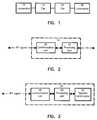
- FIG. 1is a very general illustration of a train that includes two locomotives separated by two cars;
- FIG. 2is a functional block diagram of a controller module of the remote control system for a locomotive in accordance with a non-limiting example of implementation of the present invention
- FIG. 3is a functional block diagram of the remote control module of the remote control system for a locomotive in accordance with a non-limiting example of implementation of the present invention
- FIG. 4is a block diagram of the processing unit of the controller module illustrated in FIG. 2;
- FIGS. 5 a and 5 bdepict flowcharts illustrating the operation of the remote control system for a locomotive according to a non-limiting example of implementation of the present invention
- FIGS. 6 a , 6 b , 6 c and 6 ddepict functional block diagrams of a system for remotely controlling a train in accordance with an alternative aspect of the invention.
- FIG. 1illustrates schematically a train configuration of the type that could be used advantageously in connection with an embodiment of the invention.
- the train configurationincludes from left to right a first locomotive 10 , a first car 12 , a second car 14 and a second locomotive 16 .
- a number of variations of the train configuration shown in FIG. 1can be considered.
- the locomotives 10 , 16be located at the respective ends of the train. Possibilities where the ends of the train are formed by cars instead of locomotives are within the ambit of this invention.
- the present inventionprovides a novel remote control system for the train configuration illustrated in FIG. 1 .
- the remote control systemincludes three main components namely a remote control module and two controller modules.
- the remote control moduleis the device with which the operator conveys commands to the train.
- the remote control moduleincludes a transmitter unit operative to send signals.
- the remote control moduleincludes a transceiver unit operative to send and receive signals.
- the controller modulesare mounted in the respective locomotives 10 , 16 and they interface with existing throttle/brake actuators and other controls and sensors on the locomotive such as to control the locomotive in response to commands issued by the remote control module.
- the remote control modulecan be in the form of a portable module comprising a housing that encloses the electronic circuitry and a battery supplying electrical power to operate the remote control module.
- a plurality of manually operable levers and switchesproject outside the housing and are provided to dial-in train speed, brake and other possible settings.
- the remote control modulecan be in the form of a console fixed in either one of the locomotives 10 , 16 .
- FIG. 3provides a functional block diagram of the remote control module that is designated by the reference numeral 24 .
- the remote control module 24includes three to main units or blocks namely, the operator control panel 30 , a processing unit 28 and a communication unit 26 .
- the operator control panel 30encompasses the various manually operable levers and switches designed to be selectively actuated by the operator in order to dial-in train speed, throttle, brake and other possible settings.
- the operator control panel 30generates electrical signals that are directed to the processing unit 28 .
- the structure of the processing unit 28will be described in greater detail later in this to specification.
- the processing unit 28receives the raw electrical signals from the operator control panel 30 and generates a digital train status word that reflects the desired functional status of the train.
- the digital train statusexpresses in what direction the train should be moving, at what speed, whether the headlights on the locomotive should be on, whether the horn should be activated, etc.
- the digital train statusmay express what throttle/brake should be applied instead of or in addition to a desired speed indicator.
- the digital train status wordis part of a packet of bits arranged according to a certain format. Various possible formats can be considered without departing from the spirit of the invention. In one specific example, the format includes a header portion, a user data portion and an error detection/correction portion.
- the header portionincludes an address that uniquely identifies the controller module to whom the packet is destined.
- the user data portionincludes the digital train status word data.
- the error detection/correction portionincludes data allowing to detect and possibly correct transmission errors.
- the error detection/correctionincludes a data element indicative of the address of the sender. Examples of error detection/correction strategies include to data parity, cyclic redundancy check (CRC), check sum, among other possibilities.
- the packet of bits generated by the processing unit 28is passed to the communication unit 26 that includes a transmitter unit.
- the transmitter unithandles outgoing signals.
- the communication unit 26includes a receiver unit handling incoming signals.
- the transmitter unitmodulates the packet to produce an RF signal.
- Frequency shift keying (FSK)is a suitable modulation technique.
- the RF signal transmitted by the remote control module 24forms a master control signal.
- the RF master control signal issued by the remote control module 24is received by a controller module 18 illustrated in FIG. 2 .
- the remote control systemincludes two controller modules 18 , one mounted on each locomotive 10 , 16 .
- the controller modules 18are identical, accordingly, only one will be described with the understanding that the structure and operation of the other controller module IS are identical,
- the controller module 18includes a communication unit 20 that in general is very similar to the communication unit 26 described earlier.
- the communication unit 20includes a transmitter unit and a receiver unit.
- the controller module 18also includes a processing unit 22 that is linked to the communication unit 20 .
- the function of the receiver unit of the communication unit 20is to demodulate the RF master control signal and to extract header information and the train status word data that are passed to the processing unit 22 .
- the structure of the processing unit 22is illustrated in FIG. 4 .
- the processing unit 22is a computing device including a central processing unit (CPU) 34 that is connected through a data bus with a memory 36 .
- the memory 36will comprise a non-volatile portion designed to retain data without loss even when the electrical power is discontinued.
- the memory 36also includes a random access memory portion divided into two segments one for holding the instructions of the program element that are executed by the CPU 34 and another one for holding data on which the program element executed by the CPU 34 operates.
- the processing unit 22also includes an input/output (I/O) interface 32 of a conventional construction that allows the processing unit 22 to exchange signals with the external world.
- I/Oinput/output
- processing unit 28is very similar to the structure of the processing unit 22 as described in connection with FIG. 4 .
- the controller module 18includes an input/output 23 that is used for exchanging signals with the locomotive in which the controller module 18 is installed.
- the input/output 23is the port through which the controller module 18 issues a local command signal to cause the locomotive to move in a certain direction and at a certain speed.
- the local command signalincludes a throttle setting information, direction of travel, brake setting information etc.
- the controller module 18receives through the input/output 23 signals from sensors in the locomotive that provide real-time information on the actual speed, direction of movement and alarms.
- the processing unit 22receives the signals from the locomotive and interprets them by using a suitable algorithm in order to adjust the local command signal such as to maintain the direction of travel and speed or throttle/brake setting specified in the master control signal from the remote control module 24 .
- the person skilled in the artwill readily appreciate that the controller module 18 may include additional input/output ports for receiving a master control signal without detracting from the spirit of the invention.
- the remote control systemstarts at step 38 in FIG. 5 a .
- the operatorsets the various controls on the control panel 30 as desired and the remote control module 24 issues the master control signal.
- the master control signalincludes an address portion that uniquely identifies the controller module 18 to whom the master control signal is destined.
- the various controller modulesare assigned respective addresses that are hardwired and that cannot be easily changed. This avoids a situation where two controller modules may be assigned by mistake the same address which may create a hazardous condition if both controller modules come within the communication range of the remote control module 24 . It is to be noted however that other methods of assigning addresses may be used such as storing the address on a programmable memory (ROM, PROM, EPROM and so on) without detracting from the spirit of the invention.
- the controller module 18receives the master control signal. Assume for the sake of this example that the controller module 18 to whom the master control signal is addressed is installed in the locomotive 10 . Note that the controller module 18 that is installed in the locomotive 16 will also receive the signal, however it will ignore it since the address portion in the signal will not match the local address. The controller module 18 in the locomotive 10 processes the master control signal and extracts the instructions contained therein.
- step 46the controller module 18 sends a signal to the remote control module acknowledging reception of the master control signal,
- the remote control modulemay, upon reception of the acknowledgment signal visually indicate to the operator that the controller module 18 in the locomotive 10 has confirmed reception of the command. It is to be noted that step 46 is essentially a method of confirming the reception of an instruction and may be omitted without detracting from the spirit of the invention.
- the processing unit 22will compute appropriate throttle and brake settings and generate a local command signal that, as described earlier, includes a throttle setting information and brake setting information among others.
- the local command signalis issued through the input/output 23 and applied to the locomotive controls as briefly described earlier.
- the processing unit 22will generate a local command signal that, as described earlier, includes a throttle setting information and a brake setting information among others.
- the local command signalis issued through the input/output 23 and applied to the locomotive controls as briefly described earlier.
- the processing unit 22will also derive a throttle setting information and a brake setting information for the other locomotive (locomotive 16 ).
- the brake settings for both locomotives 10 , 16are identical.
- the throttle settings for the locomotives 10 , 16are also essentially identical.
- the processing unit 22can compute the throttle settings and brake settings for the locomotives 10 , 16 such as to introduce delays in application of the commands between the locomotives 10 , 16 or any other differences.
- the processing unit 22inserts the throttle setting information and the brake setting information for the locomotive 16 into a packet and transmits this packet over an RF link between the two controller modules 18 .
- the RF linkis established between the communication units 20 of the controller modules 18 .
- the inter controller module communicationbe effected over a different communication channel than the communication between a controller module 18 and the remote control module 24 .
- Each channelmay be assigned a different frequency band. Alternatively, the same frequency band can be used but the channels are multiplexed by using a time division multiplexing and code division multiplexing, among others.
- Yet another possibilityis to use a single communication channel, and provide in each data packet sent a flag that indicates whether the packet is for inter controller module communication or for communication between a controller module 18 and the remote control module 24 . Yet another possibility is to use a single communication channel, and provide in each data packet sent an address that indicates to whom the packet is directed.
- the controller module 18 in the locomotive 10sends to the controller module 18 in the locomotive 16 the local control signal.
- the data packet in the local control signalincludes in the header portion the address of the controller module 1 in the locomotive 16 to ensure that this command will not be received by any other entity.
- the controller module 18 in the locomotive 16receives the local control signal.
- the controller module 18 in the locomotive 16acts as a trail and simply implements the throttle setting and the brake setting (among other possible settings) computed by the controller module 18 in the locomotive 10 .
- the implementationis materialized by the generation of the local command signal that is applied to the controls of the locomotive 16 .
- the trainis caused to move in the desired direction and the desired throttle/brake setting is applied. If any change is necessary, the operator alters the settings at the remote control module 24 and the above-described process is repeated.
- a master control signalis transmitted from the remote control module to the lead controller module at every control cycle. If a master control signal is not received within a certain number of control cycles, the lead controller module assumes that an error has occurred and the train is stopped.
- the control cycleis typically several times per second but may vary depending on the train on which the system is mounted.
- the remote control module 24generates a master control signal indicative of a switch in the lead operational status. This interaction is depicted in FIG. 5 b .
- the controller module having the lead operational statusreceives the master control signal indicative of a switch in the lead operational status.
- the controller module 18 in the locomotive 10 having the lead operational statusrelinquishes the lead operational status to the controller module 18 in the locomotive 16 having the trail operational status.
- the status of a controller module 18whether lead or trail can be identified by the value of a flag in the memory 36 of the processing unit 22 . For instance, if the flag is set this means that the controller module 18 holds the lead operational status. Otherwise, the controller module holds the trail operational status.
- a statue switchis effected by exchanging messages between the controller modules 18 over the RF link.
- the controller module 16 in the locomotive 10generates and sends over the RF link a command to the controller module 18 in the locomotive 16 to set its status flag (acquire lead operational status).
- the controller module 18 in the locomotive 16sends an acknowledgment to the controller module 18 in the locomotive 10 that confirms the acquisition of the lead operational status.
- the controller module 18 in the locomotive 10clears its status flag such as to acquire the trail operational status.
- step 64the controller module 18 in the locomotive 16 sends a control massage to the remote control module 24 to indicate that it has acquired the lead operational status.
- the remote control module 24will replace in a register implemented in the processing unit 28 the address of the controller module 18 in the locomotive 10 by the address of the controller module 18 in the locomotive 16 . Accordingly, any further communication originating from the remote control module 24 will be directed to the controller module 18 in the locomotive 16 .
- the address of the controller module 18 in the locomotive 10may be replaced by the address of the controller module 18 in the locomotive 16 prior to the remote control module sending the master control signal indicative of a status switch.
- step 64may be omitted.
- the remote control module 24initiates a switch in the lead operational status by redirecting the transmission of the master control signal from the current lead controller module to the current trail controller module.
- This interactionis depicted in FIG. 5 c .
- the controller module having the trail operational statusreceives the master control signal.
- the current trail controller modulesends a message over the RF link to the current lead controller module indicative of a switch in lead operational status.
- the current lead controller moduleno longer receiving message from the remote control module and receiving the message sent at step 104 , relinquishes the lead operational status and acquires the trail operational status.
- the original trail controller moduleacquires the lead operational status.
- the train on which are mounted the first controller module and the second controller moduleis stationary.
- the controller modules 18 and the remote control module 24communicate with one another through radio frequency links by placing in a header portion of messages data elements indicative of addresses.
- These addressesalso referred to as identifiers, allow to uniquely identify each of the components of the communication system.
- the address of a componentis communicated to the other component during an initialization phase. The system initialization will now be described with reference to FIGS. 6 a , 6 b , 6 c and 6 d.
- the Locomotive control system considered in this specific exampleis a remote control system that comprises three components, namely: a remote control module 604 , a first controller module 600 , and a second controller module 602 .
- the componentsare shown prior to any address exchange. Each component is associated to a respective address and stores this address in a memory location.
- the first controller module 600is associated to ID# 1
- the second controller module 602to ID # 2
- the remote control module 604to ID REMOTE.
- ID# 1 , ID# 2 and ID REMOTEare alphanumeric strings allowing to distinguish the various components.
- the remote control module 604establishes a first proximity data exchange transaction with the first controller module 600 allowing the first controller module 600 to received the address of the remote control module 604 (ID REMOTE) and for the remote control module 604 to receive the address of the first controller module 600 (ID # 1 ).
- the remote control module 604 and the first controller module 600store ID REMOTE and ID# 1 .
- the first proximity data exchange transactionis effected over an infrared (IR) link.
- the first proximity data exchange transactionis effected over a link selected from the set consisting of an infra red link, a coaxial cable link, a wire link and an optical cable link.
- the remote control module 604establishes a second proximity data exchange transaction with the second controller module 602 allowing the second controller module to receive the address of the remote control module 604 (ID) REMOTE), the address of the first controller module 600 (ID#) and for the remote control module 604 to received the address of the second controller module 602 (ID # 2 ).
- the remote control module 604 and the second controller module 602store ID REMOTE, ID#and ID# 2 .
- the second proximity data exchange transactionis effected over an infrared (IR) link.
- the second proximity data exchange transactionis effected over a link selected from. the set consisting of an infra red link, a coaxial cable link, a wire link and an optical cable link.
- the second controller module 602establishes a non-proximity communication link with the first controller module 600 allowing the first controller module 600 to received the address of the second controller module 602 (ID# 2 ).
- ID# 2the address of the second controller module 602
- all componentsstore ID REMOTE, ID# 1 and ID# 2 .
- the non-proximity communication linkis a radio frequency (RF) link.
- Each component 600 , 602 , 604stores the addresses of the other component in a memory unit for use when transmitting messages. Once each component has the address of the other components in the remote control system, the remote control module 604 communicates over an RF channel with either the first controller module or the second controller module to assign the lead operational status. Once the lead operational status has been assigned, the controller module having the lead operational status communicates over a RF channel with the other controller module to assign to it a trail operational status.
- the functional elements of the process described earlierare implemented in software that is in the form of program elements executed in the processing units 22 , 28 in the controller modules 18 and in the remote control module 24 .
Landscapes
- Engineering & Computer Science (AREA)
- Mechanical Engineering (AREA)
- Electric Propulsion And Braking For Vehicles (AREA)
Abstract
Description
Claims (23)
Priority Applications (2)
| Application Number | Priority Date | Filing Date | Title |
|---|---|---|---|
| US10/041,797US6449536B1 (en) | 2000-07-14 | 2002-01-07 | Remote control system for locomotives |
| US10/201,427US6789004B2 (en) | 2000-07-14 | 2002-07-22 | Remote control system for locomotives |
Applications Claiming Priority (2)
| Application Number | Priority Date | Filing Date | Title |
|---|---|---|---|
| US61611500A | 2000-07-14 | 2000-07-14 | |
| US10/041,797US6449536B1 (en) | 2000-07-14 | 2002-01-07 | Remote control system for locomotives |
Related Parent Applications (1)
| Application Number | Title | Priority Date | Filing Date |
|---|---|---|---|
| US61611500AContinuation | 2000-07-14 | 2000-07-14 |
Related Child Applications (1)
| Application Number | Title | Priority Date | Filing Date |
|---|---|---|---|
| US10/201,427ContinuationUS6789004B2 (en) | 2000-07-14 | 2002-07-22 | Remote control system for locomotives |
Publications (2)
| Publication Number | Publication Date |
|---|---|
| US20020059018A1 US20020059018A1 (en) | 2002-05-16 |
| US6449536B1true US6449536B1 (en) | 2002-09-10 |
Family
ID=24468082
Family Applications (2)
| Application Number | Title | Priority Date | Filing Date |
|---|---|---|---|
| US10/041,797Expired - LifetimeUS6449536B1 (en) | 2000-07-14 | 2002-01-07 | Remote control system for locomotives |
| US10/201,427Expired - LifetimeUS6789004B2 (en) | 2000-07-14 | 2002-07-22 | Remote control system for locomotives |
Family Applications After (1)
| Application Number | Title | Priority Date | Filing Date |
|---|---|---|---|
| US10/201,427Expired - LifetimeUS6789004B2 (en) | 2000-07-14 | 2002-07-22 | Remote control system for locomotives |
Country Status (1)
| Country | Link |
|---|---|
| US (2) | US6449536B1 (en) |
Cited By (49)
| Publication number | Priority date | Publication date | Assignee | Title |
|---|---|---|---|---|
| US20020146082A1 (en)* | 1999-03-25 | 2002-10-10 | Canac Inc. | Method and apparatus for assigning addresses to components in a control system |
| US20030198298A1 (en)* | 1999-03-25 | 2003-10-23 | Canac, Inc. | [Method and Apparatus for Assigning Addresses to Components in a Control System] |
| US20040073357A1 (en)* | 2000-12-14 | 2004-04-15 | Michael Schliep | Method and system for controlling and/or regulation a load of a vehicle |
| US20040088086A1 (en)* | 2002-10-31 | 2004-05-06 | Canac Inc. | Method and apparatus implementing a communication protocol for use in a control system |
| US20040100938A1 (en)* | 2002-07-31 | 2004-05-27 | Cattron-Theimeg, Inc. | System and method for wireless remote control of locomotives |
| US20040117076A1 (en)* | 2002-12-02 | 2004-06-17 | Canac Inc. | Remote control system for locomotives using a TDMA communication protocol |
| US20040117073A1 (en)* | 2002-12-02 | 2004-06-17 | Canac Inc. | Method and apparatus for controlling a locomotive |
| US20040122566A1 (en)* | 2002-12-20 | 2004-06-24 | Canac Inc. | Apparatus and method for providing automated brake pipe testing |
| US20040131112A1 (en)* | 1999-03-30 | 2004-07-08 | Canac Inc. | Method and apparatus for assigning addresses to components in a control system |
| US20040129840A1 (en)* | 2002-12-20 | 2004-07-08 | Folkert Horst | Remote control system for a locomotive |
| US20040183362A1 (en)* | 2003-03-17 | 2004-09-23 | New York Air Brake Corporation | Brake system cut-out control |
| US6799098B2 (en) | 2000-09-01 | 2004-09-28 | Beltpack Corporation | Remote control system for a locomotive using voice commands |
| US20040238695A1 (en)* | 2003-05-30 | 2004-12-02 | Folkert Horst | Method and apparatus for transmitting signals to a locomotive control device |
| US6853890B1 (en) | 2003-09-22 | 2005-02-08 | Beltpack Corporation | Programmable remote control system and apparatus for a locomotive |
| US20050045058A1 (en)* | 2003-08-26 | 2005-03-03 | Donnelly Frank Wegner | Method for monitoring and controlling locomotives |
| US20050065673A1 (en)* | 2003-09-22 | 2005-03-24 | Canac Inc. | Configurable remote control system for a locomotive |
| US20050075764A1 (en)* | 2003-09-22 | 2005-04-07 | Canac Inc. | Remote control system for a locomotive having user authentication capabilities |
| US20050189815A1 (en)* | 2004-02-27 | 2005-09-01 | Bryant Robert F. | Method and apparatus for swapping lead and remote locomotives in a distributed power railroad train |
| US20050209777A1 (en)* | 2004-03-22 | 2005-09-22 | General Electric Company | Operator location tracking for remote control rail yard switching |
| US20050253022A1 (en)* | 2002-03-19 | 2005-11-17 | Peltz David M | Remotely controlled locomotive car-kicking control |
| US6984946B2 (en) | 2002-02-27 | 2006-01-10 | Railpower Technologies Corp. | Method for monitoring and controlling traction motors in locomotives |
| US7064507B2 (en) | 2004-02-17 | 2006-06-20 | Railpower Technologies Corp. | Managing wheel skid in a locomotive |
| US7069122B1 (en)* | 2002-03-08 | 2006-06-27 | Control Chief Corporation | Remote locomotive control |
| US20070142984A1 (en)* | 2005-12-21 | 2007-06-21 | General Electric Company | Protection against exceeding the braking capability of remote controlled locomotives |
| US7236859B2 (en) | 2000-09-01 | 2007-06-26 | Cattron Intellectual Property Corporation | Remote control system for a locomotive |
| US20070179688A1 (en)* | 2005-12-30 | 2007-08-02 | Canadian National Railway Company | System and method for computing rail car switching solutions in a switchyard |
| US7304445B2 (en) | 2004-08-09 | 2007-12-04 | Railpower Technologies Corp. | Locomotive power train architecture |
| US20070277695A1 (en)* | 2006-06-02 | 2007-12-06 | Sells Gary L | Multiple track railroad system |
| US20070282494A1 (en)* | 2006-06-06 | 2007-12-06 | Moffitt Robert L | Controlling Communications Linking Among Locomotives Having Duplicate Road Numbers |
| US7309929B2 (en) | 2005-04-25 | 2007-12-18 | Railpower Technologies Corporation | Locomotive engine start method |
| US7349797B2 (en) | 2004-03-30 | 2008-03-25 | Railpower Technologies Corp | Emission management for a hybrid locomotive |
| US20080077285A1 (en)* | 2004-12-09 | 2008-03-27 | Kumar Ajith K | Methods and Systems for Improved Throttle Control and Coupling Control for Locomotive and Associated Train |
| US20080264291A1 (en)* | 2005-10-19 | 2008-10-30 | Rail Power Technologies Corp | Design of a Large Low Maintenance Battery Pack for a Hybrid Locomotive |
| US7507500B2 (en) | 2004-05-17 | 2009-03-24 | Railpower Technologies Corp. | Design of a large battery pack for a hybrid locomotive |
| US7565867B2 (en) | 2004-09-03 | 2009-07-28 | Frank Wegner Donnelly | Multiple engine locomotive configuration |
| US20100222948A1 (en)* | 2005-12-30 | 2010-09-02 | Canadian National Railway Company | System and method for computing rail car switching solutions by assessing space availability in a classification track on the basis of block pull time |
| US20100324760A1 (en)* | 2005-12-30 | 2010-12-23 | Canadian National Railway Company | System and method for computing rail car switching solutions in a switchyard using an iterative method |
| US20100324759A1 (en)* | 2005-12-30 | 2010-12-23 | Canadian National Railway Company | System and method for computing rail car switching solutions in a switchyard including logic to re-switch cars for block size |
| US7940016B2 (en) | 2004-08-09 | 2011-05-10 | Railpower, Llc | Regenerative braking methods for a hybrid locomotive |
| US20110249628A1 (en)* | 2003-12-22 | 2011-10-13 | David Michael Peltz | Method and system for providing redundancy in railroad communication equipment |
| US20120035790A1 (en)* | 2005-12-30 | 2012-02-09 | Canadian National Railway Company | System and method for computing railcar switching sequence in a switchyard |
| US20120126065A1 (en)* | 2010-11-18 | 2012-05-24 | Kristopher Smith | System and method for remotely controlling rail vehicles |
| US8290646B2 (en) | 2008-03-27 | 2012-10-16 | Hetronic International, Inc. | Remote control system implementing haptic technology for controlling a railway vehicle |
| US8295992B2 (en) | 2008-03-27 | 2012-10-23 | Hetronic International, Inc. | Remote control system having a touchscreen for controlling a railway vehicle |
| US8332086B2 (en) | 2005-12-30 | 2012-12-11 | Canadian National Railway Company | System and method for forecasting the composition of an outbound train in a switchyard |
| US9248825B2 (en) | 2007-05-16 | 2016-02-02 | General Electric Company | Method of operating vehicle and associated system |
| US9796396B2 (en) | 2016-02-18 | 2017-10-24 | Electro-Motive Diesel, Inc. | Train control system having remote configuration interface |
| US10597055B2 (en) | 2015-11-02 | 2020-03-24 | Methode Electronics, Inc. | Locomotive control networks |
| US11208125B2 (en)* | 2016-08-08 | 2021-12-28 | Transportation Ip Holdings, Llc | Vehicle control system |
Families Citing this family (29)
| Publication number | Priority date | Publication date | Assignee | Title |
|---|---|---|---|---|
| US7120428B2 (en)* | 2001-08-17 | 2006-10-10 | Control Chief Corporation | Remote locomotive control |
| DE10311836B4 (en)* | 2003-03-18 | 2006-10-05 | Integrated Electronic Systems !Sys Consulting Gmbh | Remote controlled industrial device |
| US7729818B2 (en)* | 2003-12-09 | 2010-06-01 | General Electric Company | Locomotive remote control system |
| US7233844B2 (en)* | 2004-03-22 | 2007-06-19 | General Electric Company | Locomotive remote control system with diagnostic display |
| US7915342B2 (en)* | 2005-11-28 | 2011-03-29 | Fina Techology, Inc. | Breathable films |
| US7455370B2 (en)* | 2005-11-29 | 2008-11-25 | New York Air Brake Corporation | Brake pipe control system with remote radio car |
| US7922127B2 (en)* | 2008-04-28 | 2011-04-12 | General Electric Company | System and method for pacing a powered system traveling along a route |
| US8676410B2 (en)* | 2008-06-02 | 2014-03-18 | General Electric Company | System and method for pacing a plurality of powered systems traveling along a route |
| US8380361B2 (en)* | 2008-06-16 | 2013-02-19 | General Electric Company | System, method, and computer readable memory medium for remotely controlling the movement of a series of connected vehicles |
| US8239078B2 (en)* | 2009-03-14 | 2012-08-07 | General Electric Company | Control of throttle and braking actions at individual distributed power locomotives in a railroad train |
| US8504513B2 (en)* | 2009-11-25 | 2013-08-06 | Microsoft Corporation | Auto-generation of code for performing a transform in an extract, transform, and load process |
| US8521345B2 (en)* | 2011-12-28 | 2013-08-27 | General Electric Company | System and method for rail vehicle time synchronization |
| FR2992620B1 (en)* | 2012-06-27 | 2014-08-15 | Alstom Transport Sa | TRAIN AND METHOD FOR DETERMINING THE COMPOSITION OF SUCH A SAFETY TRAIN |
| US9371076B2 (en) | 2012-09-14 | 2016-06-21 | General Electric Company | Method and apparatus for positioning a vehicle |
| US8942869B2 (en) | 2012-09-14 | 2015-01-27 | General Electric Company | Method and apparatus for positioning a rail vehicle or rail vehicle consist |
| US9145863B2 (en)* | 2013-03-15 | 2015-09-29 | General Electric Company | System and method for controlling automatic shut-off of an engine |
| US9026282B2 (en) | 2012-11-30 | 2015-05-05 | Electro-Motive Diesel, Inc. | Two-tiered hierarchically distributed locomotive control system |
| US8935020B2 (en) | 2012-11-30 | 2015-01-13 | Electro-Motive Diesel, Inc. | Back-up and redundancy of modules in locomotive distributed control systems |
| US8954210B2 (en) | 2012-11-30 | 2015-02-10 | Electro-Motive Diesel, Inc. | Distributed control system for a locomotive |
| US8868267B2 (en) | 2012-11-30 | 2014-10-21 | Electro-Motive Diesel, Inc. | Remote update in locomotive distributed control systems |
| US10034119B2 (en)* | 2014-11-10 | 2018-07-24 | General Electric Company | System and method for testing communication in a vehicle system |
| US12030539B2 (en) | 2015-02-06 | 2024-07-09 | Cattron North America, Inc. | Devices, systems, and methods related to tracking location of operator control units for locomotives |
| US11926353B2 (en) | 2015-02-06 | 2024-03-12 | Cattron North America, Inc. | Devices, systems, and methods related to tracking location of operator control units for locomotives |
| US11046335B2 (en)* | 2015-02-06 | 2021-06-29 | Cattron North America, Inc. | Devices, systems, and methods related to tracking location of operator control units for locomotives |
| WO2017004229A1 (en)* | 2015-06-30 | 2017-01-05 | Laird Technologies, Inc. | Monitoring and controlling of distributed machines |
| US9932048B2 (en) | 2016-02-16 | 2018-04-03 | Progress Rail Locomotive Inc. | Controller for a locomotive |
| US11854309B2 (en) | 2021-10-30 | 2023-12-26 | Cattron North America, Inc. | Systems and methods for remotely controlling locomotives with gestures |
| US12109993B2 (en) | 2022-04-19 | 2024-10-08 | Transportation Ip Holdings, Llc | Vehicle control system and method |
| US11851094B1 (en) | 2022-11-04 | 2023-12-26 | Bnsf Railway Company | Remote engine speed control |
Citations (17)
| Publication number | Priority date | Publication date | Assignee | Title |
|---|---|---|---|---|
| US3639755A (en) | 1970-01-02 | 1972-02-01 | Gen Signal Corp | Remote control of a locomotive |
| US4401035A (en)* | 1980-07-03 | 1983-08-30 | Kansas City Southern Railway Company | Control device for multiple unit locomotive systems |
| US4582280A (en) | 1983-09-14 | 1986-04-15 | Harris Corporation | Railroad communication system |
| US4687258A (en) | 1985-12-11 | 1987-08-18 | Canadian National Railway Company | Remote control system for a locomotive |
| US4702291A (en) | 1985-09-16 | 1987-10-27 | General Signal Corporation | Propulsion system for integral trains |
| US4830437A (en)* | 1988-03-25 | 1989-05-16 | American Standard Inc. | Brake assurance circuit to preserve proper locomotive operting status |
| US5332297A (en) | 1993-04-26 | 1994-07-26 | Westinghouse Air Brake Company | Charging cut-off valve arrangement for microprocessor-based electropneumatic locomotive brake control system |
| US5495520A (en) | 1993-06-25 | 1996-02-27 | Nec Corporation | Cordless telephone system and identification code setting method therefor |
| EP0704590A2 (en) | 1994-09-30 | 1996-04-03 | Sony Corporation | Remote operating system |
| US5570284A (en) | 1994-12-05 | 1996-10-29 | Westinghouse Air Brake Company | Method and apparatus for remote control of a locomotive throttle controller |
| US5685507A (en)* | 1994-04-01 | 1997-11-11 | Canac International Incorporated | Remote control system for a locomotive |
| US5691980A (en) | 1995-06-07 | 1997-11-25 | General Electric Company | Local communication network for power reduction and enhanced reliability in a multiple node tracking system |
| US5718487A (en)* | 1996-01-23 | 1998-02-17 | Westinghouse Air Brake Company | Brake control system for doubled ended locomotive |
| US5884146A (en) | 1993-05-27 | 1999-03-16 | Caterpillar Inc. | Apparatus and method for establishing a radio frequency communications link between a controller and a remote controllable system |
| US5986579A (en) | 1998-07-31 | 1999-11-16 | Westinghouse Air Brake Company | Method and apparatus for determining railcar order in a train |
| WO2000058142A1 (en) | 1999-03-25 | 2000-10-05 | Canac Inc. | Method and apparatus for assigning addresses to components in a control system |
| US6175784B1 (en)* | 1999-08-09 | 2001-01-16 | Honeywell, Inc. | Remotely operated rail car status monitor and control system |
Family Cites Families (6)
| Publication number | Priority date | Publication date | Assignee | Title |
|---|---|---|---|---|
| US3096056A (en)* | 1961-01-25 | 1963-07-02 | Westinghouse Air Brake Co | Locomotive remote control system |
| US4652057A (en)* | 1985-09-16 | 1987-03-24 | General Signal Corporation | Control system for integral trains |
| US5697583A (en)* | 1996-09-13 | 1997-12-16 | Dorne & Margolin, Inc. | Radio frequency coupler for communication between adjacent railway cars |
| US5777547A (en)* | 1996-11-05 | 1998-07-07 | Zeftron, Inc. | Car identification and ordering system |
| US6314345B1 (en)* | 1997-07-22 | 2001-11-06 | Tranz Rail Limited | Locomotive remote control system |
| US6322025B1 (en)* | 1999-11-30 | 2001-11-27 | Wabtec Railway Electronics, Inc. | Dual-protocol locomotive control system and method |
- 2002
- 2002-01-07USUS10/041,797patent/US6449536B1/ennot_activeExpired - Lifetime
- 2002-07-22USUS10/201,427patent/US6789004B2/ennot_activeExpired - Lifetime
Patent Citations (18)
| Publication number | Priority date | Publication date | Assignee | Title |
|---|---|---|---|---|
| US3639755A (en) | 1970-01-02 | 1972-02-01 | Gen Signal Corp | Remote control of a locomotive |
| US4401035A (en)* | 1980-07-03 | 1983-08-30 | Kansas City Southern Railway Company | Control device for multiple unit locomotive systems |
| US4582280A (en) | 1983-09-14 | 1986-04-15 | Harris Corporation | Railroad communication system |
| US5039038A (en)* | 1983-09-14 | 1991-08-13 | Harris Corporation | Railroad communication system |
| US4702291A (en) | 1985-09-16 | 1987-10-27 | General Signal Corporation | Propulsion system for integral trains |
| US4687258A (en) | 1985-12-11 | 1987-08-18 | Canadian National Railway Company | Remote control system for a locomotive |
| US4830437A (en)* | 1988-03-25 | 1989-05-16 | American Standard Inc. | Brake assurance circuit to preserve proper locomotive operting status |
| US5332297A (en) | 1993-04-26 | 1994-07-26 | Westinghouse Air Brake Company | Charging cut-off valve arrangement for microprocessor-based electropneumatic locomotive brake control system |
| US5884146A (en) | 1993-05-27 | 1999-03-16 | Caterpillar Inc. | Apparatus and method for establishing a radio frequency communications link between a controller and a remote controllable system |
| US5495520A (en) | 1993-06-25 | 1996-02-27 | Nec Corporation | Cordless telephone system and identification code setting method therefor |
| US5685507A (en)* | 1994-04-01 | 1997-11-11 | Canac International Incorporated | Remote control system for a locomotive |
| EP0704590A2 (en) | 1994-09-30 | 1996-04-03 | Sony Corporation | Remote operating system |
| US5570284A (en) | 1994-12-05 | 1996-10-29 | Westinghouse Air Brake Company | Method and apparatus for remote control of a locomotive throttle controller |
| US5691980A (en) | 1995-06-07 | 1997-11-25 | General Electric Company | Local communication network for power reduction and enhanced reliability in a multiple node tracking system |
| US5718487A (en)* | 1996-01-23 | 1998-02-17 | Westinghouse Air Brake Company | Brake control system for doubled ended locomotive |
| US5986579A (en) | 1998-07-31 | 1999-11-16 | Westinghouse Air Brake Company | Method and apparatus for determining railcar order in a train |
| WO2000058142A1 (en) | 1999-03-25 | 2000-10-05 | Canac Inc. | Method and apparatus for assigning addresses to components in a control system |
| US6175784B1 (en)* | 1999-08-09 | 2001-01-16 | Honeywell, Inc. | Remotely operated rail car status monitor and control system |
Non-Patent Citations (2)
| Title |
|---|
| Steve Hennessy " GE Harris Railway Electronics, 2000 International User Conference, Train Control Technology, New Perspectives for the New Millennium, Locotrol Distributed Power" Mar. 29-31, 2000. |
| Steve Hennessy Locotrol Distributed Power, New Application, Kansas City Southern Mar. 30, 2000. |
Cited By (81)
| Publication number | Priority date | Publication date | Assignee | Title |
|---|---|---|---|---|
| US6975927B2 (en) | 1999-03-25 | 2005-12-13 | Beltpack Corporation | Remote control system for locomotive with address exchange capability |
| US20020152008A1 (en)* | 1999-03-25 | 2002-10-17 | Canac Inc. | Method and apparatus for assigning addresses to components in a control system |
| US20030195671A2 (en)* | 1999-03-25 | 2003-10-16 | Canac Inc | [Method and Apparatus for Assigning Addresses to Components in a Control System] |
| US20030198298A1 (en)* | 1999-03-25 | 2003-10-23 | Canac, Inc. | [Method and Apparatus for Assigning Addresses to Components in a Control System] |
| US20030202621A2 (en)* | 1999-03-25 | 2003-10-30 | Canac Corporation | [Method and Apparatus for Assigning Addresses to Components in a Control System] |
| US20020146082A1 (en)* | 1999-03-25 | 2002-10-10 | Canac Inc. | Method and apparatus for assigning addresses to components in a control system |
| US7167510B2 (en)* | 1999-03-25 | 2007-01-23 | Cattron Intellectual Property Corporation | Method and apparatus for assigning addresses to components in a control system |
| US7164709B2 (en) | 1999-03-25 | 2007-01-16 | Cattron Intellectual Property Corporation | Method and apparatus for assigning addresses to components in a control system |
| US20060239379A1 (en)* | 1999-03-25 | 2006-10-26 | Canac Inc. | Method and apparatus for assigning addresses to components in a control system |
| US7126985B2 (en) | 1999-03-25 | 2006-10-24 | Cattron Intellectual Property Corporation | Method and apparatus for assigning addresses to components in a control system |
| US20040131112A1 (en)* | 1999-03-30 | 2004-07-08 | Canac Inc. | Method and apparatus for assigning addresses to components in a control system |
| US7203228B2 (en) | 1999-03-30 | 2007-04-10 | Cattron Intellectual Property Corporation | Method and apparatus for assigning addresses to components in a control system |
| US7236859B2 (en) | 2000-09-01 | 2007-06-26 | Cattron Intellectual Property Corporation | Remote control system for a locomotive |
| US6799098B2 (en) | 2000-09-01 | 2004-09-28 | Beltpack Corporation | Remote control system for a locomotive using voice commands |
| US20040073357A1 (en)* | 2000-12-14 | 2004-04-15 | Michael Schliep | Method and system for controlling and/or regulation a load of a vehicle |
| US6984946B2 (en) | 2002-02-27 | 2006-01-10 | Railpower Technologies Corp. | Method for monitoring and controlling traction motors in locomotives |
| US7069122B1 (en)* | 2002-03-08 | 2006-06-27 | Control Chief Corporation | Remote locomotive control |
| US7520472B2 (en) | 2002-03-19 | 2009-04-21 | General Electric Company | Remotely controlled locomotive car-kicking control |
| US20050253022A1 (en)* | 2002-03-19 | 2005-11-17 | Peltz David M | Remotely controlled locomotive car-kicking control |
| US7792089B2 (en)* | 2002-07-31 | 2010-09-07 | Cattron-Theimeg, Inc. | System and method for wireless remote control of locomotives |
| US20040100938A1 (en)* | 2002-07-31 | 2004-05-27 | Cattron-Theimeg, Inc. | System and method for wireless remote control of locomotives |
| US6928342B2 (en) | 2002-10-31 | 2005-08-09 | Beltpack Corporation | Method and apparatus implementing a communication protocol for use in a control system |
| US20040088086A1 (en)* | 2002-10-31 | 2004-05-06 | Canac Inc. | Method and apparatus implementing a communication protocol for use in a control system |
| US20040117073A1 (en)* | 2002-12-02 | 2004-06-17 | Canac Inc. | Method and apparatus for controlling a locomotive |
| US20040117076A1 (en)* | 2002-12-02 | 2004-06-17 | Canac Inc. | Remote control system for locomotives using a TDMA communication protocol |
| US20040129840A1 (en)* | 2002-12-20 | 2004-07-08 | Folkert Horst | Remote control system for a locomotive |
| US20040122566A1 (en)* | 2002-12-20 | 2004-06-24 | Canac Inc. | Apparatus and method for providing automated brake pipe testing |
| US20040183362A1 (en)* | 2003-03-17 | 2004-09-23 | New York Air Brake Corporation | Brake system cut-out control |
| US6964456B2 (en) | 2003-03-17 | 2005-11-15 | New York Air Brake Corporation | Brake system cut-out control |
| US6863247B2 (en)* | 2003-05-30 | 2005-03-08 | Beltpack Corporation | Method and apparatus for transmitting signals to a locomotive control device |
| US20040238695A1 (en)* | 2003-05-30 | 2004-12-02 | Folkert Horst | Method and apparatus for transmitting signals to a locomotive control device |
| US20050045058A1 (en)* | 2003-08-26 | 2005-03-03 | Donnelly Frank Wegner | Method for monitoring and controlling locomotives |
| US7124691B2 (en) | 2003-08-26 | 2006-10-24 | Railpower Technologies Corp. | Method for monitoring and controlling locomotives |
| US6853890B1 (en) | 2003-09-22 | 2005-02-08 | Beltpack Corporation | Programmable remote control system and apparatus for a locomotive |
| US20050075764A1 (en)* | 2003-09-22 | 2005-04-07 | Canac Inc. | Remote control system for a locomotive having user authentication capabilities |
| US20050065673A1 (en)* | 2003-09-22 | 2005-03-24 | Canac Inc. | Configurable remote control system for a locomotive |
| US20110249628A1 (en)* | 2003-12-22 | 2011-10-13 | David Michael Peltz | Method and system for providing redundancy in railroad communication equipment |
| US8706327B2 (en)* | 2003-12-22 | 2014-04-22 | General Electric Company | Method and system for providing redundancy in railroad communication equipment |
| US7084602B2 (en) | 2004-02-17 | 2006-08-01 | Railpower Technologies Corp. | Predicting wheel slip and skid in a locomotive |
| US7064507B2 (en) | 2004-02-17 | 2006-06-20 | Railpower Technologies Corp. | Managing wheel skid in a locomotive |
| US7467830B2 (en) | 2004-02-17 | 2008-12-23 | Railpower Technologies Corp. | Managing wheel slip in a locomotive |
| US20050189815A1 (en)* | 2004-02-27 | 2005-09-01 | Bryant Robert F. | Method and apparatus for swapping lead and remote locomotives in a distributed power railroad train |
| US7715956B2 (en)* | 2004-02-27 | 2010-05-11 | General Electric Company | Method and apparatus for swapping lead and remote locomotives in a distributed power railroad train |
| US7239943B2 (en) | 2004-03-22 | 2007-07-03 | General Electric Company | Operator location tracking for remote control rail yard switching |
| US20050209777A1 (en)* | 2004-03-22 | 2005-09-22 | General Electric Company | Operator location tracking for remote control rail yard switching |
| US7349797B2 (en) | 2004-03-30 | 2008-03-25 | Railpower Technologies Corp | Emission management for a hybrid locomotive |
| US7507500B2 (en) | 2004-05-17 | 2009-03-24 | Railpower Technologies Corp. | Design of a large battery pack for a hybrid locomotive |
| US7304445B2 (en) | 2004-08-09 | 2007-12-04 | Railpower Technologies Corp. | Locomotive power train architecture |
| US7940016B2 (en) | 2004-08-09 | 2011-05-10 | Railpower, Llc | Regenerative braking methods for a hybrid locomotive |
| US7565867B2 (en) | 2004-09-03 | 2009-07-28 | Frank Wegner Donnelly | Multiple engine locomotive configuration |
| US20080077285A1 (en)* | 2004-12-09 | 2008-03-27 | Kumar Ajith K | Methods and Systems for Improved Throttle Control and Coupling Control for Locomotive and Associated Train |
| US8280569B2 (en)* | 2004-12-09 | 2012-10-02 | General Electric Company | Methods and systems for improved throttle control and coupling control for locomotive and associated train |
| US7514807B2 (en) | 2005-04-25 | 2009-04-07 | Railpower Technologies Corp. | Alternator boost method |
| US7518254B2 (en) | 2005-04-25 | 2009-04-14 | Railpower Technologies Corporation | Multiple prime power source locomotive control |
| US7309929B2 (en) | 2005-04-25 | 2007-12-18 | Railpower Technologies Corporation | Locomotive engine start method |
| US7661370B2 (en) | 2005-10-19 | 2010-02-16 | Railpower, Llc | Design of a large low maintenance battery pack for a hybrid locomotive |
| US20080264291A1 (en)* | 2005-10-19 | 2008-10-30 | Rail Power Technologies Corp | Design of a Large Low Maintenance Battery Pack for a Hybrid Locomotive |
| US8311689B2 (en) | 2005-12-21 | 2012-11-13 | General Electric Company | Protection against exceeding the braking capability of remote controlled locomotives |
| US20070142984A1 (en)* | 2005-12-21 | 2007-06-21 | General Electric Company | Protection against exceeding the braking capability of remote controlled locomotives |
| US20120035790A1 (en)* | 2005-12-30 | 2012-02-09 | Canadian National Railway Company | System and method for computing railcar switching sequence in a switchyard |
| US20100324759A1 (en)* | 2005-12-30 | 2010-12-23 | Canadian National Railway Company | System and method for computing rail car switching solutions in a switchyard including logic to re-switch cars for block size |
| US20100324760A1 (en)* | 2005-12-30 | 2010-12-23 | Canadian National Railway Company | System and method for computing rail car switching solutions in a switchyard using an iterative method |
| US20070179688A1 (en)* | 2005-12-30 | 2007-08-02 | Canadian National Railway Company | System and method for computing rail car switching solutions in a switchyard |
| US8239079B2 (en)* | 2005-12-30 | 2012-08-07 | Canadian National Railway Company | System and method for computing rail car switching sequence in a switchyard |
| US20100222948A1 (en)* | 2005-12-30 | 2010-09-02 | Canadian National Railway Company | System and method for computing rail car switching solutions by assessing space availability in a classification track on the basis of block pull time |
| US8332086B2 (en) | 2005-12-30 | 2012-12-11 | Canadian National Railway Company | System and method for forecasting the composition of an outbound train in a switchyard |
| US7827919B2 (en) | 2006-06-02 | 2010-11-09 | Sells Gary L | Multiple track railroad system |
| US20070277695A1 (en)* | 2006-06-02 | 2007-12-06 | Sells Gary L | Multiple track railroad system |
| US8534201B2 (en) | 2006-06-02 | 2013-09-17 | Gary L. Sells | Multiple track railroad system |
| US20070282494A1 (en)* | 2006-06-06 | 2007-12-06 | Moffitt Robert L | Controlling Communications Linking Among Locomotives Having Duplicate Road Numbers |
| US9248825B2 (en) | 2007-05-16 | 2016-02-02 | General Electric Company | Method of operating vehicle and associated system |
| US8483887B2 (en) | 2008-03-27 | 2013-07-09 | Hetronic International, Inc. | Remote control system having a touchscreen for controlling a railway vehicle |
| US8380363B2 (en) | 2008-03-27 | 2013-02-19 | Hetronic International, Inc. | Remote control system having a touchscreen for controlling a railway vehicle |
| US8509964B2 (en) | 2008-03-27 | 2013-08-13 | Hetronic International, Inc. | Remote control system having a touchscreen for controlling a railway vehicle |
| US8295992B2 (en) | 2008-03-27 | 2012-10-23 | Hetronic International, Inc. | Remote control system having a touchscreen for controlling a railway vehicle |
| US8290646B2 (en) | 2008-03-27 | 2012-10-16 | Hetronic International, Inc. | Remote control system implementing haptic technology for controlling a railway vehicle |
| US8532842B2 (en)* | 2010-11-18 | 2013-09-10 | General Electric Company | System and method for remotely controlling rail vehicles |
| US20120126065A1 (en)* | 2010-11-18 | 2012-05-24 | Kristopher Smith | System and method for remotely controlling rail vehicles |
| US10597055B2 (en) | 2015-11-02 | 2020-03-24 | Methode Electronics, Inc. | Locomotive control networks |
| US9796396B2 (en) | 2016-02-18 | 2017-10-24 | Electro-Motive Diesel, Inc. | Train control system having remote configuration interface |
| US11208125B2 (en)* | 2016-08-08 | 2021-12-28 | Transportation Ip Holdings, Llc | Vehicle control system |
Also Published As
| Publication number | Publication date |
|---|---|
| US20030040853A1 (en) | 2003-02-27 |
| US20020059018A1 (en) | 2002-05-16 |
| US6789004B2 (en) | 2004-09-07 |
Similar Documents
| Publication | Publication Date | Title |
|---|---|---|
| US6449536B1 (en) | Remote control system for locomotives | |
| US5681015A (en) | Radio-based electro-pneumatic control communications system | |
| AU739794B2 (en) | Segmented brake pipe train control system and related method | |
| CN102292253B (en) | Distributed power locomotives is as the repeater communicated between train head-tail device | |
| US8112189B2 (en) | Method and system for providing redundancy in railroad communication equipment | |
| CN102320316B (en) | CTCS-3-level train control center system | |
| CN101511656B (en) | Interface system for wire distributed power | |
| EP0257909B1 (en) | Communicating vital control signals | |
| US5383717A (en) | Brake control of helper locomotive | |
| TW353250B (en) | Method and apparatus for the remote monitoring and configuration of electronic control systems | |
| US9254854B2 (en) | Method and device for determining the train length of a plurality of coupled railway traction vehicles | |
| US6837466B2 (en) | Method and system for coordinated transfer of control of a remote controlled locomotive | |
| CA2313918C (en) | Remote control system for locomotives | |
| SE465458B (en) | SPAARLEDNINGSSYSTEM | |
| EP0976633A2 (en) | A control and communication system for railway trains | |
| JP5943723B2 (en) | Information converter | |
| US5862062A (en) | Parallel programming of a plurality of nodes in a communication network | |
| RU85231U1 (en) | DIGITAL TRANSMISSION DEVICE FOR DIGITAL COMMUNICATION (UPDL) | |
| SU1530515A1 (en) | Apparatus for automatic locomotive signalling | |
| JPS62131866A (en) | Car operation information transmitter |
Legal Events
| Date | Code | Title | Description |
|---|---|---|---|
| STCF | Information on status: patent grant | Free format text:PATENTED CASE | |
| AS | Assignment | Owner name:BELTPACK CORPORATION, CANADA Free format text:ASSIGNMENT OF ASSIGNORS INTEREST;ASSIGNOR:CANAC INC.;REEL/FRAME:015642/0377 Effective date:20040430 | |
| AS | Assignment | Owner name:ARGOSY INVESTMENT PARTNERS II, L.P., PENNSYLVANIA Free format text:SECURITY INTEREST;ASSIGNOR:CATTRON INTELLECTUAL PROPERTY CORPORATION;REEL/FRAME:016116/0653 Effective date:20041015 | |
| AS | Assignment | Owner name:CATTRON INTELLECTUAL PROPERTY CORPORATION, PENNSYL Free format text:ASSIGNMENT OF ASSIGNORS INTEREST;ASSIGNOR:BELTPACK CORPORATION;REEL/FRAME:015583/0354 Effective date:20041015 | |
| FPAY | Fee payment | Year of fee payment:4 | |
| FEPP | Fee payment procedure | Free format text:PAT HOLDER CLAIMS SMALL ENTITY STATUS, ENTITY STATUS SET TO SMALL (ORIGINAL EVENT CODE: LTOS); ENTITY STATUS OF PATENT OWNER: LARGE ENTITY | |
| FPAY | Fee payment | Year of fee payment:8 | |
| FEPP | Fee payment procedure | Free format text:PAT HOLDER NO LONGER CLAIMS SMALL ENTITY STATUS, ENTITY STATUS SET TO UNDISCOUNTED (ORIGINAL EVENT CODE: STOL); ENTITY STATUS OF PATENT OWNER: LARGE ENTITY | |
| FPAY | Fee payment | Year of fee payment:12 | |
| AS | Assignment | Owner name:CATTRON-THEIMEG, INC., PENNSYLVANIA Free format text:MERGER AND CHANGE OF NAME;ASSIGNORS:CATTRON INTELLECTUAL PROPERTY CORPORATION;CATTRON INTELLECTUAL PROPERTY CORPORATION;REEL/FRAME:047704/0955 Effective date:20131231 | |
| AS | Assignment | Owner name:LAIRD CONTROLS NORTH AMERICA INC., PENNSYLVANIA Free format text:MERGER AND CHANGE OF NAME;ASSIGNORS:CATTRON-THEIMEG, INC.;CATTRON-THEIMEG, INC.;REEL/FRAME:048407/0964 Effective date:20140825 | |
| AS | Assignment | Owner name:CATTRON INTELLECTUAL PROPERTY CORPORATION, PENNSYL Free format text:RELEASE BY SECURED PARTY;ASSIGNOR:ARGOSY INVESTMENT PARTNERS II, L.P.;REEL/FRAME:048029/0474 Effective date:20190103 | |
| AS | Assignment | Owner name:CATTRON NORTH AMERICA, INC., OHIO Free format text:CHANGE OF NAME;ASSIGNOR:LAIRD CONTROLS NORTH AMERICA INC.;REEL/FRAME:049677/0840 Effective date:20190220 |