US6448731B1 - Apparatus and method for controlling an electric motor - Google Patents
Apparatus and method for controlling an electric motorDownload PDFInfo
- Publication number
- US6448731B1 US6448731B1US09/601,172US60117200AUS6448731B1US 6448731 B1US6448731 B1US 6448731B1US 60117200 AUS60117200 AUS 60117200AUS 6448731 B1US6448731 B1US 6448731B1
- Authority
- US
- United States
- Prior art keywords
- motor
- values
- electric assist
- determining
- controller
- Prior art date
- Legal status (The legal status is an assumption and is not a legal conclusion. Google has not performed a legal analysis and makes no representation as to the accuracy of the status listed.)
- Expired - Lifetime
Links
Images


Classifications
- B—PERFORMING OPERATIONS; TRANSPORTING
- B62—LAND VEHICLES FOR TRAVELLING OTHERWISE THAN ON RAILS
- B62D—MOTOR VEHICLES; TRAILERS
- B62D5/00—Power-assisted or power-driven steering
- B62D5/04—Power-assisted or power-driven steering electrical, e.g. using an electric servo-motor connected to, or forming part of, the steering gear
- B62D5/0457—Power-assisted or power-driven steering electrical, e.g. using an electric servo-motor connected to, or forming part of, the steering gear characterised by control features of the drive means as such
- B62D5/0481—Power-assisted or power-driven steering electrical, e.g. using an electric servo-motor connected to, or forming part of, the steering gear characterised by control features of the drive means as such monitoring the steering system, e.g. failures
- B62D5/0487—Power-assisted or power-driven steering electrical, e.g. using an electric servo-motor connected to, or forming part of, the steering gear characterised by control features of the drive means as such monitoring the steering system, e.g. failures detecting motor faults
- B—PERFORMING OPERATIONS; TRANSPORTING
- B62—LAND VEHICLES FOR TRAVELLING OTHERWISE THAN ON RAILS
- B62D—MOTOR VEHICLES; TRAILERS
- B62D5/00—Power-assisted or power-driven steering
- B62D5/04—Power-assisted or power-driven steering electrical, e.g. using an electric servo-motor connected to, or forming part of, the steering gear
- B62D5/0457—Power-assisted or power-driven steering electrical, e.g. using an electric servo-motor connected to, or forming part of, the steering gear characterised by control features of the drive means as such
- B62D5/046—Controlling the motor
- B62D5/0463—Controlling the motor calculating assisting torque from the motor based on driver input
- H—ELECTRICITY
- H02—GENERATION; CONVERSION OR DISTRIBUTION OF ELECTRIC POWER
- H02P—CONTROL OR REGULATION OF ELECTRIC MOTORS, ELECTRIC GENERATORS OR DYNAMO-ELECTRIC CONVERTERS; CONTROLLING TRANSFORMERS, REACTORS OR CHOKE COILS
- H02P21/00—Arrangements or methods for the control of electric machines by vector control, e.g. by control of field orientation
- H02P21/22—Current control, e.g. using a current control loop
Definitions
- the present inventionrelates to an apparatus and method for controlling an electric motor and, more particularly, to a method and apparatus for controlling an electric assist motor in an electric assist steering system.
- Motor control systems for electric assist steering systemstypically are equipped with various circuitry and controls for monitoring and detecting abnormal conditions in the electric motor being monitored. For example, it may be desirable to detect when the electric motor is not commutating properly or when the motor or the drive circuitry has overheated.
- U.S. Pat. No. 5,257,828 and U.S. Pat. No. 5,517,415both to Miller et al. and assigned to TRW Inc., disclose approaches for detecting abnormal conditions in an electric assist steering system and for controlling the electric assist motor accordingly.
- U.S. Pat. No. 5,726,545discloses a method for controlling electric current in a servo motor using DQ conversion for converting three-phase current into a two-phase DQ reference coordinate.
- U.S. Pat. No. 5,670,854 to Matsuura et al.discloses a control system for an induction motor in an electric assist steering systems where the induction motor does not include permanent magnets.
- the Matsuura et al. patentfurther discloses using DQ conversion in the control process for the electric assist motor.
- the present inventionis directed to a method and apparatus for controlling an electric assist steering system.
- a first set of motor control valuesare determined in response to applied steering torque.
- the electric motoris energized in response to this first set of motor control values.
- Motor control valuesare determined from the motor operating values.
- a second set of motor control valuesare determined in response to applied steering torque. The motor is disabled when the determined motor control values from the motor operating values is inconsistent with the determined second set of motor control values responsive to applied steering torque.
- motor current control valuesare determined in response to applied steering torque.
- a DQ controllertransforms the determined current control values into three-phase drive signals which are applied to the motor.
- DQ valuesare determined from the monitored motor current and position values.
- DQ valuesare determined in response to applied steering torque.
- the DQ values responsive to applied steering torqueare compared against the DQ values responsive to monitored motor current and position. The motor is disabled if the comparison indicates an inconsistency.
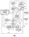
- FIG. 1is a schematic representation of a system in accordance with a preferred embodiment of the present invention
- FIG. 2is a flow diagram illustrating the operation of a first controller of the system of FIG. 1 in accordance with a preferred embodiment of the present invention
- FIG. 3is a flow diagram illustrating the operation of a second controller of the system of FIG. 1 in accordance with a preferred embodiment of the present invention.
- FIG. 4is a flow diagram illustrating the operation of the first controller of the system of FIG. 1 in accordance with an alternative preferred embodiment of the present invention.
- FIG. 1illustrates a vehicle electric assist steering system 10 that includes a vehicle steering wheel 12 connected to an input shaft 14 .
- the input shaft 14is operatively connected to a pinion shaft 18 through a torsion bar (not shown).
- the torsion bartwists in response to the torque applied to the vehicle steering wheel 12 to permit relative rotation between the input shaft 14 and an output shaft 18 in a known manner.
- a torque sensor 16is operatively connected to the input shaft 14 and the output shaft 18 to sense the applied steering torque.
- the output shaft 18is operatively connected to steerable wheels schematically illustrated at block 20 .
- the electric motor 22is a multi-phase motor such as a three-phase permanent magnet alternating current (“PMAC”) motor of known configuration with phases A, B, and C.
- the PMAC motor 22includes a plurality of stator poles disposed in a generally circular array around a rotor. Each of the stator poles includes a plurality of conductive windings which form phases A, B, and C.
- the rotoris rotatably disposed within the stator housing to rotate about a central axis.
- the rotoralso includes a plurality of spaced apart poles arranged in a generally circular array with permanent magnets disposed on each pole. When the stator windings are energized by appropriate AC signals, the energized stator poles create an electric field which effects rotation of the rotor.
- the electric motor 22may be operatively connected with a rack and pinion gear set of the vehicle.
- the motor 22may be operatively connected with the steering column, such as to the pinion or output shaft 18 .
- the system 10may be used in accordance with the present invention with either a rack drive, pinion drive, column drive, or any type of electric assist steering system.
- the system 10also may be adapted for use with an electric powered hydraulic steering system.
- the systemincludes the torque sensor 16 which senses the amount of steering torque applied to the steering wheel 12 .
- the torque sensor 16may be an inductive torque sensor, an optical torque sensor, a resistive torque sensor, or any other known type of torque sensor.
- the torque sensor 16provides a signal 24 to a main controller 26 indicative of the amount of applied steering torque.
- the controller 26preferably is a microprocessor or microcomputer programmed for controlling the electric assist motor 22 in response to one or more input signals, including the torque sensor signal 24 .
- Other vehicle parameters 28such as from a vehicle speed sensor, soft start control circuitry, and/or other desirable vehicle condition parameters, provide signal(s) 30 to the controller 26 indicative of the sensed parameters.
- the controller 26also includes memory having a look-up table 29 .
- the controller 26receives electrical power from a power supply, such as the vehicle battery 32 that has been appropriately filtered and maintained as a desired voltage level through a voltage regulator 34 .
- a motor position sensor 36is operatively connected with the electric assist motor 22 through connection 38 .
- the motor position sensor 36monitors the relative position of the rotor and the stator of the motor 22 and provides a motor position signal 40 to the controller 26 .
- the controller 26determines a current command value in response to the applied input torque signal 24 , the motor position signal 40 , and signal 30 . Specifically, the controller 26 is preprogrammed to determine a level of motor current, suitably from values stored in the look-up table 29 , according to the input torque signal 24 , the input position signal 40 , and other parameter signals 30 . The determined level of motor current energizes the electric assist motor 22 to provide an appropriate amount of steering assist.
- a motor control arrangement for an electric assist steering systemis disclosed in U.S. Pat. No. 5,475,289 to McLaughlin et al., which is assigned to TRW Inc.
- the McLaughlin et al. patentdiscloses an apparatus and method for deriving the current command value by interpolating between current profile curves which are stored in appropriate memory.
- the interpolation performed by the controller 26is similar to that disclosed in the McLaughlin et al. patent and may be linear or non-linear.
- the controller 26interpolates between current profile curves to derive a motor current command signal 42 for each of the plurality of phases of the motor 22 .
- the motor current command signal 42is supplied to a drive circuit 44 which, in turn, provides an appropriate amount of electric current to each of the plurality of phases of the motor 22 .
- the drive circuit 44is electrically connected through electrical connection 45 to a power supply, suitably battery 32 or a voltage regulator.
- the controller 26includes a pulse-width-modulating circuitry that provides the output signal 42 in the form of a plurality of pulse-width-modulated signals.
- the pulse-width-modulated signalsare provided to an array of switching devices, preferably FETs, which comprise the drive circuit 44 . Accordingly, the FETs of the drive circuit 44 are pulse-width modulated by the current command signal 42 to provide a desired alternating current to each of the phases of the electric motor 22 at a level commensurate with the applied steering torque.
- the controller 26also is programmed to perform suitable diagnostics to ensure proper operation of the system 10 and, in particular, of the electric assist motor 22 and the drive circuit 44 .
- the system 10includes a temperature sensor 46 operatively connected to the drive circuit 44 by a connection schematically illustrated at 48 .
- the temperature sensor 46provides a temperature sensor signal 50 to the main controller 26 indicative of the temperature of the drive circuit 44 .
- the temperature sensing and diagnostic functionpreferably includes those disclosed in U.S. Pat. No. 5,257,828 to Miller et al. which is assigned to TRW Inc. and incorporated herein by reference.
- the system 10also may include stall detection circuitry through which the controller 26 may detect a motor stall condition in the electric assist motor 22 .
- the stall conditionfor example, may be detected by collectively monitoring the applied torque signal 24 in combination with sensing the commutation of the motor through a signal 47 from the motor 22 to the main controller 26 .
- An example of a suitable stall detection operationis disclosed in U.S. Pat. No. 5,517,415 also to Miller et al., which is assigned to TRW Inc. and incorporated herein by reference.
- the stall detection functionmay also include a temperature dependent operation, whereby the system gain is controlled as a function of temperature.
- the system 10also includes a secondary or overseer controller 54 .
- the secondary controller 54operates to verify proper operation of the electric assist motor 22 in response to the applied torque signal 24 . This, in turn, provides a system check on the control process performed by the main controller 26 .
- the secondary controller 54is electrically connected to a power supply, such as the voltage regulator 34 .
- the secondary controller 54like the main controller 26 , receives the torque sensor signal 24 and the motor position sensor signal 40 as inputs. These input signals enable the secondary controller 54 to determine a motor voltage or motor current value.
- the motor voltage or current valuecorresponds to a respective motor voltage or current that will provide the amount of steering assist corresponding to sensed input torque. Accordingly, the secondary controller 54 can compare the determined value with the actual motor voltage or current to determine if an abnormal condition exists.
- the secondary controller 54also receives a signal 56 indicative of a monitored value of the actual voltage and/or current of each of the plurality of phases A, B, and C of the electric assist motor 22 .
- the systemincludes a voltage or current monitoring device 58 that is electrically connected with and monitors a voltage or current condition of each phase A, B, and C of the electric assist motor 22 .
- the monitoring device 58provides the voltage or current signal 56 to the secondary controller 54 .
- the monitoring device 58provides signals indicative of the actual instantaneous voltage value for each of the plurality phases A, B, and C of the electric assist motor 22 .
- the monitoring device 58also could be connected directly with the electric motor 22 .
- the secondary controller 54determines a DQ vector quantity, which is a two-dimensioned representation of the motor voltage or current according to the applied input torque and motor position.
- the secondary controller 54converts the DQ voltage or current vector into a three phase voltage or current, depending on whether the monitoring device 58 is configured to provide voltage or current values. If the converted phase values agree with the monitored phase values from monitoring device 58 , operation of the electric assist motor continues under the control of controller 26 uninterrupted. However, if the converted phase values differ from the monitored phase values by a predetermined amount, the secondary controller 54 determines the occurrence of an abnormality and provides a signal 60 to disable the electric assist motor 22 .
- a power relay 62is electrically connected with two or more phases of the electric assist motor 22 and responsive to the secondary controller 54 . Accordingly, upon the power relay 62 receiving the disable command signal 60 , the power relay opens to disconnect the electric assist motor 22 from its power supply 32 , thereby removing steering assist. The vehicle can still be steered manually.
- the main controller 26preferably utilizes a look-up table 29 to determine the current drive signals in response to input parameters so as to control the electric assist motor 22 .
- Necessary input parametersinclude the applied torque signal 24 and the motor position signal 40 .
- step 100the applied input torque is monitored by the main controller 26 through the torque sensor signal 24 .
- step 102the main controller 26 monitors the relative position between the rotor and stator of the motor 22 through the motor position signal 40 .
- step 104a motor current value is determined in response to the motor torque signal 24 and the motor position signal 40 , preferably from the look-up 29 within the main controller 26 .
- the actual control valuewill be interpolated for smooth control.
- the controller 26may mathematically calculate corresponding current values by known motor control algorithms.
- the current valuescorrespond to the amount of current that is to be applied to the electric assist motor 22 by the drive circuit 44 in order to achieve the desired amount of steering assist.
- the processproceeds to step 106 in which the main controller 26 outputs the current drive signal 42 which are provided to the drive circuit 44 .
- the phase current drive signal 42preferably is a plurality of pulse-width-modulated signals for gating the individual FETs that form the drive circuit 44 .
- the PWM drive signals 42gate the FETs so as to provide a desired AC signal for each of the motor phases.
- drive circuit 42provides AC current signals to each phase of the three phase electric motor 22 , each signal being phase shifted by 120°. Accordingly, the FETs of the drive circuit 44 are controlled by the main controller 26 to provide an appropriate AC input current at each of the phases A, B, and C according to the applied input torque or any other desired vehicle parameters.
- the processthen proceeds to step 108 where the main controller 26 performs diagnostics.
- the diagnosticsmay include temperature sensing of the FETs in the drive circuit 44 , stall detection of the electric assist motor 22 by signal 47 as well as other known diagnostic functions.
- Such diagnosticsalso may include monitoring a communication link 66 between the secondary controller 54 and the main controller 26 . Pertinent data may be exchanged over the communication link 66 to enable the main controller 26 to diagnose a possible failure of the overseer 54 .
- the secondary controller 54also might monitor the operation of the main controller 26 so as to determine the existence of an abnormal condition in the main controller. Upon completing the desired diagnostics, the process returns to step 100 .
- control process of the secondary controller 54begins at step 120 by the secondary controller monitoring the applied input torque signal 24 .
- step 124the process continues to step 124 with the secondary controller 54 monitoring the relative position between the rotor and stator of the motor 22 .
- the motor position datais provided through the motor position signal 40 from the motor position sensor 36 .
- step 126the secondary controller 54 determines a DQ vector as a function of the applied steering torque and motor position.
- motor torquemay mathematically be determined as the vector cross product of the rotor flux and the stator magnito-motive force (“MMF”).
- MMFstator magnito-motive force
- the DQ vector control analysisis a two-dimensional representation of a motor current or voltage corresponding to the value of the applied steering torque indicated by the applied torque signal 24 .
- the DQ vectormay be represented as either a voltage or current vector, each having a D-axis component and a Q-axis component in the rotating coordinates.
- the D-axisrefers to the direct or permanent flux linkage associated with the rotor magnets of the electric assist motor 22 , i.e., the rotor flux.
- the Q-axisrefers to the stator MMF, which leads the rotor flux by 90°, i.e., it is in quadrature with the D-axis.
- the individual D-axis and Q-axis components of motor voltage or currentare determined by DQ transformation as a function of the applied torque value and the motor position value.
- the determined DQ vector valueis a two-dimensional vector representation of the motor current or motor voltage corresponding to the three-phase motor current or voltage values as determined by the main controller 26 .
- the accuracy of the DQ transformationis improved by obtaining a relatively high resolution motor position value from the motor position sensor 36 .
- the motor position sensormay include a plurality of sensing devices configured to provide the desired high resolution indication of motor position.
- step 128the secondary controller 54 converts the DQ vector value into a three-phase voltage value by applying an appropriate DQ transform to the previously determined DQ vector value. Provided that the main controller and secondary controller are operating properly, the converted three-phase voltage or current values should agree with the actual voltage or current values of the electric assist motor 22 .
- step 130the secondary controller 54 monitors the phase voltages currents of each phase A, B, and C of the electric assist motor 22 .
- the converted phase voltage values and the monitored phase voltage or current valuesare appropriately normalized to a desired voltage level, suitably according to the voltage level from voltage regulator 34 .
- step 132the secondary controller 54 compares the converted phase voltage values and the monitored phase voltage or current values. This determination is made to verify that the electric assist motor 22 is operating at a level corresponding to the applied steering torque. This, in turn, also verifies whether the electric motor 22 and the drive circuit 44 are responding properly to the current command signals 42 from the main controller 26 .
- step 134it is determined whether the converted phase voltage values agree with the monitored phase voltage values of the electric assist motor 22 , i.e., are they within a predetermined amount. If the determination is affirmative, the process returns to step 120 where the process repeats. On the other hand, if the determination is negative, such as where the converted phase values differ from the monitored phase values by a predetermined amount, the process proceeds to step 136 .
- step 136the secondary controller 54 provides signal 60 to the power relay 62 so as to disable the electric assist motor 22 .
- the power relay 62deactivates the electric assist motor 22 by disconnecting the motor 22 from the power supply 32 .
- the main controller 26 described abovepreferably utilizes a look-up table to determine the three-phase current command signal 42
- the current command signalmay be determined in using a DQ vector transformation, as illustrated in FIG. 4 and described above with respect to the secondary controller 54 .
- the secondary controllercould utilize either DQ transformation, as described above, or it could be configured to include a look-up table to determine the phase voltage or current values. The secondary controller 54 then would confirm the proper operation of the electric motor 22 as described above.
- the secondary controller 54also may be configured to communicate with the main controller 26 over communication link 66 . Such communication could be used to effect an incremental increase or decrease in the current command signal 42 in response to the results of the comparison performed by the secondary controller 54 .
- the secondary controller 54transforming the DQ vector values to three phase voltage or current values prior to step 134
- the monitored three phase voltage or current values from the monitoring device 58could be transformed into DQ axis components.
- the values of such monitored DQ axis componentsare then compared with the corresponding values of the determined DQ vector to determine whether such values substantially agree. If the values do not agree (e.g., they differ by more than a predetermined amount) the secondary controller 54 disables the electric assist motor 22 through activation of the power relay 62 , as described above.
- a method for controlling an electric assist motor in accordance with the present inventioncomprises determining a first set of motor control values in response to applied steering torque, energizing the electric motor in response to the first set of motor control values, the motor having operating values when energized, determining a motor control value from the motor operating values, determining a second set of motor control values in response to the applied steering torque, and disabling the motor when the determined motor control value from the motor operating values is inconsistent with the determined second set of motor control values responsive to applied steering torque.
- Being inconsistentmeans that the signs of the determined values are not equal or that the determined values are different by a predetermined amount.
Landscapes
- Engineering & Computer Science (AREA)
- Chemical & Material Sciences (AREA)
- Combustion & Propulsion (AREA)
- Transportation (AREA)
- Mechanical Engineering (AREA)
- Power Engineering (AREA)
- Steering Control In Accordance With Driving Conditions (AREA)
- Control Of Ac Motors In General (AREA)
- Power Steering Mechanism (AREA)
- Control Of Motors That Do Not Use Commutators (AREA)
Abstract
Description
Claims (15)
Priority Applications (1)
| Application Number | Priority Date | Filing Date | Title |
|---|---|---|---|
| US09/601,172US6448731B1 (en) | 1999-02-11 | 2000-02-10 | Apparatus and method for controlling an electric motor |
Applications Claiming Priority (3)
| Application Number | Priority Date | Filing Date | Title |
|---|---|---|---|
| US11978499P | 1999-02-11 | 1999-02-11 | |
| US09/601,172US6448731B1 (en) | 1999-02-11 | 2000-02-10 | Apparatus and method for controlling an electric motor |
| PCT/US2000/003378WO2000048047A1 (en) | 1999-02-11 | 2000-02-10 | Apparatus and method for controlling an electric assist steering system |
Publications (1)
| Publication Number | Publication Date |
|---|---|
| US6448731B1true US6448731B1 (en) | 2002-09-10 |
Family
ID=22386387
Family Applications (1)
| Application Number | Title | Priority Date | Filing Date |
|---|---|---|---|
| US09/601,172Expired - LifetimeUS6448731B1 (en) | 1999-02-11 | 2000-02-10 | Apparatus and method for controlling an electric motor |
Country Status (6)
| Country | Link |
|---|---|
| US (1) | US6448731B1 (en) |
| EP (1) | EP1071982B1 (en) |
| JP (1) | JP3403175B2 (en) |
| BR (1) | BR0004031A (en) |
| DE (1) | DE60036162T2 (en) |
| WO (1) | WO2000048047A1 (en) |
Cited By (17)
| Publication number | Priority date | Publication date | Assignee | Title |
|---|---|---|---|---|
| US20030071594A1 (en)* | 2001-08-17 | 2003-04-17 | Kleinau Julie A. | Feedback parameter estimation for electric machines |
| US20030076064A1 (en)* | 2001-08-17 | 2003-04-24 | Kleinau Julie A. | Feedforward parameter estimation for electric machines |
| US20030076065A1 (en)* | 2001-08-17 | 2003-04-24 | Shafer Daniel W. | Active temperature estimation for electric machines |
| US20030076061A1 (en)* | 2001-08-17 | 2003-04-24 | Kleinau Julie A. | Combined feedforward and feedback parameter estimation for electric machines |
| US20050168186A1 (en)* | 2004-02-03 | 2005-08-04 | Fanuc Ltd. | Servomotor control device for robot and robot having the device |
| US20060161519A1 (en)* | 1999-05-24 | 2006-07-20 | Stewart Robert L | Prioritizing network management traffic |
| US20060201736A1 (en)* | 2005-03-11 | 2006-09-14 | Fardoun Abbas A | Method and apparatus for detecting a failed temperature sensor in an electric assist steering system |
| US20080060451A1 (en)* | 2006-09-12 | 2008-03-13 | Daniel Puzio | Optical torque sensor |
| US7543679B2 (en) | 2006-07-28 | 2009-06-09 | Delphi Technologies, Inc. | Compensation of periodic sensor errors in electric power steering systems |
| US7549504B2 (en) | 2006-07-28 | 2009-06-23 | Delphi Technologies, Inc. | Quadrant dependent active damping for electric power steering |
| US7576506B2 (en) | 2001-12-11 | 2009-08-18 | Delphi Technologies, Inc. | Feedforward parameter estimation for electric machines |
| US7725227B2 (en) | 2006-12-15 | 2010-05-25 | Gm Global Technology Operations, Inc. | Method, system, and apparatus for providing enhanced steering pull compensation |
| US20130038253A1 (en)* | 2010-04-28 | 2013-02-14 | Panasonic Corporation | Motor device and power tool |
| US20160079895A1 (en)* | 2014-09-12 | 2016-03-17 | Panasonic Intellectual Property Management Co., Ltd. | Electric power tool |
| US10343525B2 (en)* | 2014-12-16 | 2019-07-09 | Byd Company Limited | Electric vehicle, active safety control system for electric vehicle, and control method for active safety control system of electric vehicle |
| US10343712B2 (en)* | 2016-07-27 | 2019-07-09 | Denso Corporation | Electric power steering system |
| US11018611B2 (en)* | 2017-04-03 | 2021-05-25 | Denso Corporation | Control apparatus for multi-phase rotating electric machine |
Families Citing this family (8)
| Publication number | Priority date | Publication date | Assignee | Title |
|---|---|---|---|---|
| US6338016B1 (en)* | 1999-03-08 | 2002-01-08 | Trw Inc. | Method and apparatus for detecting a motor stall condition in an electric assist steering system |
| JP2002238293A (en) | 2001-02-14 | 2002-08-23 | Mitsubishi Electric Corp | Motor control device |
| JP3983128B2 (en)* | 2002-07-26 | 2007-09-26 | 株式会社ジェイテクト | Vehicle steering control system |
| JP4027339B2 (en)* | 2004-04-20 | 2007-12-26 | 本田技研工業株式会社 | Electric power steering device |
| JP2008247108A (en)* | 2007-03-29 | 2008-10-16 | Daikin Ind Ltd | Power steering apparatus and driving method thereof |
| DE102008042390A1 (en)* | 2008-09-26 | 2010-04-01 | Zf Friedrichshafen Ag | Error-state identifying method for induction machine, involves comparing measured voltage between reference and representative potentials with expected voltage between reference and representative potentials using comparator |
| JP5941871B2 (en)* | 2013-05-28 | 2016-06-29 | 本田技研工業株式会社 | Electric power steering device |
| KR102187486B1 (en)* | 2020-06-16 | 2020-12-07 | 에스케이씨솔믹스 주식회사 | Method and apparatus for decision for status of a robot |
Citations (22)
| Publication number | Priority date | Publication date | Assignee | Title |
|---|---|---|---|---|
| US4660671A (en) | 1985-10-23 | 1987-04-28 | Trw Inc. | Electric steering gear |
| US4719396A (en) | 1985-05-27 | 1988-01-12 | Honda Giken Kogyo Kabushiki Kaisha | Electric motor drive circuit for electric power steering systems for vehicles |
| US4895216A (en) | 1986-05-06 | 1990-01-23 | Aisin Seiki Kabushikikaisha | Electrically driven power steering apparatus |
| US5355315A (en) | 1991-06-29 | 1994-10-11 | Koyo Seiko Co., Ltd. | Electric power steering apparatus |
| US5361210A (en) | 1991-09-28 | 1994-11-01 | Koyo Seiko Co., Ltd. | Current control for electric power steering apparatus motor |
| JPH07115788A (en) | 1993-10-14 | 1995-05-02 | Hitachi Ltd | Motor control device |
| US5475289A (en) | 1994-11-04 | 1995-12-12 | Trw Inc. | Method and apparatus for controlling an electric assist steering system using two-dimensional interpolation for current commands |
| US5504404A (en) | 1993-09-17 | 1996-04-02 | Matsushita Electric Industrial Co., Ltd. | Method and apparatus for controlling motor |
| JPH08107602A (en) | 1994-10-06 | 1996-04-23 | Matsushita Electric Ind Co Ltd | Motor control circuit |
| JPH08205388A (en) | 1995-01-27 | 1996-08-09 | Aisin Seiki Co Ltd | DC motor abnormality detection device |
| JPH08251975A (en) | 1995-03-09 | 1996-09-27 | Nippon Seiko Kk | Electric power steering device |
| JPH0974793A (en) | 1995-09-01 | 1997-03-18 | Mitsubishi Electric Corp | Motor control device |
| JPH09172703A (en) | 1995-12-20 | 1997-06-30 | Denso Corp | Device for controlling motor for driving electric vehicle |
| US5656911A (en) | 1994-12-27 | 1997-08-12 | Fuji Electric Company | Circuit for driving permanent-magnet synchronous motor using proportional controller |
| US5670854A (en) | 1994-12-14 | 1997-09-23 | Matsushita Electric Industrial Co., Ltd. | Control system for an induction motor |
| US5689170A (en) | 1994-12-27 | 1997-11-18 | Nissan Motor Co., Ltd. | Fail-safe control apparatus for electric vehicle driving motor |
| US5726545A (en) | 1995-06-30 | 1998-03-10 | Fanuc Ltd. | Current controlling method for servo motor |
| US5747957A (en) | 1996-04-25 | 1998-05-05 | Mitsubishi Denki Kabushiki Kaisha | Method of controlling vectors in motor and vector-controlling inverter device |
| US5796228A (en) | 1996-09-04 | 1998-08-18 | Mitsubishi Denki Kabushiki Kaisha | Method of controlling rotary magnet multi-phase synchronous motor and control therefor |
| US5877603A (en) | 1995-09-14 | 1999-03-02 | Fanuc Ltd | Electric current control method for a servomotor |
| US5913913A (en) | 1996-04-30 | 1999-06-22 | Mitsubishi Denki Kabushiki Kaisha | Control apparatus for motor-driven power steering system of motor vehicle |
| US6152255A (en)* | 1997-07-14 | 2000-11-28 | Honda Giken Kogyo Kabushiki Kaisha | Electric power steering apparatus |
Family Cites Families (2)
| Publication number | Priority date | Publication date | Assignee | Title |
|---|---|---|---|---|
| US5257828A (en) | 1992-06-03 | 1993-11-02 | Trw Inc. | Method and apparatus for controlling damping in an electric assist steering system for vehicle yaw rate control |
| US5517415A (en) | 1994-10-26 | 1996-05-14 | Trw Inc. | Method and apparatus for detecting a motor stall condition in an electric assist steering system |
- 2000
- 2000-02-10EPEP00911746Apatent/EP1071982B1/ennot_activeExpired - Lifetime
- 2000-02-10DEDE60036162Tpatent/DE60036162T2/ennot_activeExpired - Lifetime
- 2000-02-10USUS09/601,172patent/US6448731B1/ennot_activeExpired - Lifetime
- 2000-02-10BRBR0004031-2Apatent/BR0004031A/ennot_activeIP Right Cessation
- 2000-02-10WOPCT/US2000/003378patent/WO2000048047A1/enactiveIP Right Grant
- 2000-02-10JPJP2000598902Apatent/JP3403175B2/ennot_activeExpired - Lifetime
Patent Citations (24)
| Publication number | Priority date | Publication date | Assignee | Title |
|---|---|---|---|---|
| US4719396A (en) | 1985-05-27 | 1988-01-12 | Honda Giken Kogyo Kabushiki Kaisha | Electric motor drive circuit for electric power steering systems for vehicles |
| US4660671A (en) | 1985-10-23 | 1987-04-28 | Trw Inc. | Electric steering gear |
| US4895216A (en) | 1986-05-06 | 1990-01-23 | Aisin Seiki Kabushikikaisha | Electrically driven power steering apparatus |
| US5355315A (en) | 1991-06-29 | 1994-10-11 | Koyo Seiko Co., Ltd. | Electric power steering apparatus |
| US5361210A (en) | 1991-09-28 | 1994-11-01 | Koyo Seiko Co., Ltd. | Current control for electric power steering apparatus motor |
| US5504404A (en) | 1993-09-17 | 1996-04-02 | Matsushita Electric Industrial Co., Ltd. | Method and apparatus for controlling motor |
| JPH07115788A (en) | 1993-10-14 | 1995-05-02 | Hitachi Ltd | Motor control device |
| JPH08107602A (en) | 1994-10-06 | 1996-04-23 | Matsushita Electric Ind Co Ltd | Motor control circuit |
| US5475289A (en) | 1994-11-04 | 1995-12-12 | Trw Inc. | Method and apparatus for controlling an electric assist steering system using two-dimensional interpolation for current commands |
| US5670854A (en) | 1994-12-14 | 1997-09-23 | Matsushita Electric Industrial Co., Ltd. | Control system for an induction motor |
| US5701066A (en)* | 1994-12-14 | 1997-12-23 | Matshushita Electric Industrial Co., Ltd. | Control system for an induction motor |
| US5656911A (en) | 1994-12-27 | 1997-08-12 | Fuji Electric Company | Circuit for driving permanent-magnet synchronous motor using proportional controller |
| US5689170A (en) | 1994-12-27 | 1997-11-18 | Nissan Motor Co., Ltd. | Fail-safe control apparatus for electric vehicle driving motor |
| JPH08205388A (en) | 1995-01-27 | 1996-08-09 | Aisin Seiki Co Ltd | DC motor abnormality detection device |
| JPH08251975A (en) | 1995-03-09 | 1996-09-27 | Nippon Seiko Kk | Electric power steering device |
| US5726545A (en) | 1995-06-30 | 1998-03-10 | Fanuc Ltd. | Current controlling method for servo motor |
| JPH0974793A (en) | 1995-09-01 | 1997-03-18 | Mitsubishi Electric Corp | Motor control device |
| US5787376A (en) | 1995-09-01 | 1998-07-28 | Mitsubishi Denki Kabushiki Kaisha | Power steering motor control unit with driving mode correction |
| US5877603A (en) | 1995-09-14 | 1999-03-02 | Fanuc Ltd | Electric current control method for a servomotor |
| JPH09172703A (en) | 1995-12-20 | 1997-06-30 | Denso Corp | Device for controlling motor for driving electric vehicle |
| US5747957A (en) | 1996-04-25 | 1998-05-05 | Mitsubishi Denki Kabushiki Kaisha | Method of controlling vectors in motor and vector-controlling inverter device |
| US5913913A (en) | 1996-04-30 | 1999-06-22 | Mitsubishi Denki Kabushiki Kaisha | Control apparatus for motor-driven power steering system of motor vehicle |
| US5796228A (en) | 1996-09-04 | 1998-08-18 | Mitsubishi Denki Kabushiki Kaisha | Method of controlling rotary magnet multi-phase synchronous motor and control therefor |
| US6152255A (en)* | 1997-07-14 | 2000-11-28 | Honda Giken Kogyo Kabushiki Kaisha | Electric power steering apparatus |
Cited By (26)
| Publication number | Priority date | Publication date | Assignee | Title |
|---|---|---|---|---|
| US20060161519A1 (en)* | 1999-05-24 | 2006-07-20 | Stewart Robert L | Prioritizing network management traffic |
| US7071649B2 (en) | 2001-08-17 | 2006-07-04 | Delphi Technologies, Inc. | Active temperature estimation for electric machines |
| US20030076065A1 (en)* | 2001-08-17 | 2003-04-24 | Shafer Daniel W. | Active temperature estimation for electric machines |
| US20030076061A1 (en)* | 2001-08-17 | 2003-04-24 | Kleinau Julie A. | Combined feedforward and feedback parameter estimation for electric machines |
| US6900607B2 (en)* | 2001-08-17 | 2005-05-31 | Delphi Technologies, Inc. | Combined feedforward and feedback parameter estimation for electric machines |
| US20030076064A1 (en)* | 2001-08-17 | 2003-04-24 | Kleinau Julie A. | Feedforward parameter estimation for electric machines |
| US7199549B2 (en) | 2001-08-17 | 2007-04-03 | Delphi Technologies, Inc | Feedback parameter estimation for electric machines |
| US20030071594A1 (en)* | 2001-08-17 | 2003-04-17 | Kleinau Julie A. | Feedback parameter estimation for electric machines |
| US7576506B2 (en) | 2001-12-11 | 2009-08-18 | Delphi Technologies, Inc. | Feedforward parameter estimation for electric machines |
| US20050168186A1 (en)* | 2004-02-03 | 2005-08-04 | Fanuc Ltd. | Servomotor control device for robot and robot having the device |
| US20060201736A1 (en)* | 2005-03-11 | 2006-09-14 | Fardoun Abbas A | Method and apparatus for detecting a failed temperature sensor in an electric assist steering system |
| US7163080B2 (en)* | 2005-03-11 | 2007-01-16 | Trw Automotive U.S. Llc | Method and apparatus for detecting a failed temperature sensor in an electric assist steering system |
| US7549504B2 (en) | 2006-07-28 | 2009-06-23 | Delphi Technologies, Inc. | Quadrant dependent active damping for electric power steering |
| US7543679B2 (en) | 2006-07-28 | 2009-06-09 | Delphi Technologies, Inc. | Compensation of periodic sensor errors in electric power steering systems |
| WO2008033386A3 (en)* | 2006-09-12 | 2008-07-03 | Black & Decker Inc | Optical torque sensor |
| US20080060451A1 (en)* | 2006-09-12 | 2008-03-13 | Daniel Puzio | Optical torque sensor |
| US7591195B2 (en) | 2006-09-12 | 2009-09-22 | Black & Decker Inc. | Optical torque sensor |
| US7725227B2 (en) | 2006-12-15 | 2010-05-25 | Gm Global Technology Operations, Inc. | Method, system, and apparatus for providing enhanced steering pull compensation |
| US8903606B2 (en) | 2006-12-15 | 2014-12-02 | Steering Solutiions IP Holding Corporation | Method, system, and apparatus for providing enhanced steering pull compensation |
| US20130038253A1 (en)* | 2010-04-28 | 2013-02-14 | Panasonic Corporation | Motor device and power tool |
| US8872451B2 (en)* | 2010-04-28 | 2014-10-28 | Panasonic Corporation | Motor device and power tool |
| US20160079895A1 (en)* | 2014-09-12 | 2016-03-17 | Panasonic Intellectual Property Management Co., Ltd. | Electric power tool |
| US9553534B2 (en)* | 2014-09-12 | 2017-01-24 | Panasonic Intellectual Property Management Co., Ltd. | Electric power tool |
| US10343525B2 (en)* | 2014-12-16 | 2019-07-09 | Byd Company Limited | Electric vehicle, active safety control system for electric vehicle, and control method for active safety control system of electric vehicle |
| US10343712B2 (en)* | 2016-07-27 | 2019-07-09 | Denso Corporation | Electric power steering system |
| US11018611B2 (en)* | 2017-04-03 | 2021-05-25 | Denso Corporation | Control apparatus for multi-phase rotating electric machine |
Also Published As
| Publication number | Publication date |
|---|---|
| EP1071982A1 (en) | 2001-01-31 |
| WO2000048047A1 (en) | 2000-08-17 |
| EP1071982B1 (en) | 2007-08-29 |
| JP2002536955A (en) | 2002-10-29 |
| DE60036162T2 (en) | 2008-05-21 |
| EP1071982A4 (en) | 2005-04-13 |
| BR0004031A (en) | 2000-11-21 |
| JP3403175B2 (en) | 2003-05-06 |
| DE60036162D1 (en) | 2007-10-11 |
Similar Documents
| Publication | Publication Date | Title |
|---|---|---|
| US6448731B1 (en) | Apparatus and method for controlling an electric motor | |
| US6687590B2 (en) | Electric power steering apparatus | |
| JP5012258B2 (en) | Electric power steering device | |
| EP2048774B1 (en) | Rotary electric system with star-connected multiphase stator windings | |
| EP3020615B1 (en) | Electric power steering device | |
| WO2006132268A1 (en) | Electric power steering device | |
| JP5023833B2 (en) | Electric power steering apparatus and abnormality detection method | |
| US20040264075A1 (en) | Steering assist system | |
| JP3830737B2 (en) | Electric power steering control device | |
| EP3144205A1 (en) | Limp aside steering assist with estimated motor current | |
| JP2009089552A (en) | Motor drive control device and electric power steering device using motor drive control device | |
| EP1985523B1 (en) | Systems and methods for controlling torque of a motor | |
| JP2017226305A (en) | Electric power steering device | |
| US6731085B2 (en) | Method and apparatus for determining motor faults in an electric assist steering system | |
| US8981690B2 (en) | Electric power steering system | |
| JP5062010B2 (en) | Electric power steering device | |
| JP4371844B2 (en) | Brushless motor drive device | |
| US7483796B2 (en) | Method and apparatus for determining faults in an electric assist steering system | |
| US6424107B1 (en) | Apparatus and method for controlling an electric motor | |
| US7504786B2 (en) | Motor controller | |
| KR100814757B1 (en) | Implementation method of interlock circuit using estimated position information of LAC motor | |
| JP4452994B2 (en) | Electric power steering device |
Legal Events
| Date | Code | Title | Description |
|---|---|---|---|
| AS | Assignment | Owner name:TRW INC., OHIO Free format text:ASSIGNMENT OF ASSIGNORS INTEREST;ASSIGNORS:MILLER, JOSEPH D.;MCLAUGHLIN, KEVIN M.;REEL/FRAME:011069/0700;SIGNING DATES FROM 20000609 TO 20000724 | |
| STCF | Information on status: patent grant | Free format text:PATENTED CASE | |
| AS | Assignment | Owner name:JPMORGAN CHASE BANK, NEW YORK Free format text:THE US GUARANTEE AND COLLATERAL AGREEMENT;ASSIGNOR:TRW AUTOMOTIVE U.S. LLC;REEL/FRAME:014022/0720 Effective date:20030228 | |
| FPAY | Fee payment | Year of fee payment:4 | |
| FPAY | Fee payment | Year of fee payment:8 | |
| AS | Assignment | Owner name:JPMORGAN CHASE BANK, N.A., AS COLLATERAL AGENT, NE Free format text:SECURITY AGREEMENT;ASSIGNORS:TRW VEHICLE SAFETY SYSTEMS INC.;TRW AUTOMOTIVE U.S. LLC;KELSEY-HAYES COMPANY;REEL/FRAME:029529/0534 Effective date:20120928 | |
| AS | Assignment | Owner name:TRW VEHICLE SAFETY SYSTEMS INC., MICHIGAN Free format text:RELEASE OF SECURITY INTEREST;ASSIGNOR:JPMORGAN CHASE BANK, N.A.;REEL/FRAME:031645/0697 Effective date:20131028 Owner name:TRW AUTOMOTIVE U.S. LLC, MICHIGAN Free format text:RELEASE OF SECURITY INTEREST;ASSIGNOR:JPMORGAN CHASE BANK, N.A.;REEL/FRAME:031645/0697 Effective date:20131028 Owner name:KELSEY-HAYES COMPANY, MICHIGAN Free format text:RELEASE OF SECURITY INTEREST;ASSIGNOR:JPMORGAN CHASE BANK, N.A.;REEL/FRAME:031645/0697 Effective date:20131028 Owner name:TRW INTELLECTUAL PROPERTY CORP., MICHIGAN Free format text:RELEASE OF SECURITY INTEREST;ASSIGNOR:JPMORGAN CHASE BANK, N.A.;REEL/FRAME:031645/0697 Effective date:20131028 | |
| FPAY | Fee payment | Year of fee payment:12 |