US6447306B1 - PC card configuration - Google Patents
PC card configurationDownload PDFInfo
- Publication number
- US6447306B1 US6447306B1US09/795,505US79550501AUS6447306B1US 6447306 B1US6447306 B1US 6447306B1US 79550501 AUS79550501 AUS 79550501AUS 6447306 B1US6447306 B1US 6447306B1
- Authority
- US
- United States
- Prior art keywords
- card
- combination
- connector
- recited
- form factor
- Prior art date
- Legal status (The legal status is an assumption and is not a legal conclusion. Google has not performed a legal analysis and makes no representation as to the accuracy of the status listed.)
- Expired - Fee Related
Links
Images


Classifications
- H—ELECTRICITY
- H05—ELECTRIC TECHNIQUES NOT OTHERWISE PROVIDED FOR
- H05K—PRINTED CIRCUITS; CASINGS OR CONSTRUCTIONAL DETAILS OF ELECTRIC APPARATUS; MANUFACTURE OF ASSEMBLAGES OF ELECTRICAL COMPONENTS
- H05K5/00—Casings, cabinets or drawers for electric apparatus
- H05K5/02—Details
- H05K5/0256—Details of interchangeable modules or receptacles therefor, e.g. cartridge mechanisms
- H05K5/026—Details of interchangeable modules or receptacles therefor, e.g. cartridge mechanisms having standardized interfaces
- H05K5/0265—Details of interchangeable modules or receptacles therefor, e.g. cartridge mechanisms having standardized interfaces of PCMCIA type
- H05K5/0273—Details of interchangeable modules or receptacles therefor, e.g. cartridge mechanisms having standardized interfaces of PCMCIA type having extensions for peripherals, e.g. LAN, antennas
- H—ELECTRICITY
- H04—ELECTRIC COMMUNICATION TECHNIQUE
- H04L—TRANSMISSION OF DIGITAL INFORMATION, e.g. TELEGRAPHIC COMMUNICATION
- H04L12/00—Data switching networks
- H04L12/54—Store-and-forward switching systems
- H04L12/56—Packet switching systems
- H04L12/5691—Access to open networks; Ingress point selection, e.g. ISP selection
- H04L12/5692—Selection among different networks
- H—ELECTRICITY
- H04—ELECTRIC COMMUNICATION TECHNIQUE
- H04L—TRANSMISSION OF DIGITAL INFORMATION, e.g. TELEGRAPHIC COMMUNICATION
- H04L9/00—Cryptographic mechanisms or cryptographic arrangements for secret or secure communications; Network security protocols
- H04L9/40—Network security protocols
- H—ELECTRICITY
- H01—ELECTRIC ELEMENTS
- H01R—ELECTRICALLY-CONDUCTIVE CONNECTIONS; STRUCTURAL ASSOCIATIONS OF A PLURALITY OF MUTUALLY-INSULATED ELECTRICAL CONNECTING ELEMENTS; COUPLING DEVICES; CURRENT COLLECTORS
- H01R13/00—Details of coupling devices of the kinds covered by groups H01R12/70 or H01R24/00 - H01R33/00
- H01R13/64—Means for preventing incorrect coupling
- H—ELECTRICITY
- H01—ELECTRIC ELEMENTS
- H01R—ELECTRICALLY-CONDUCTIVE CONNECTIONS; STRUCTURAL ASSOCIATIONS OF A PLURALITY OF MUTUALLY-INSULATED ELECTRICAL CONNECTING ELEMENTS; COUPLING DEVICES; CURRENT COLLECTORS
- H01R2201/00—Connectors or connections adapted for particular applications
- H01R2201/06—Connectors or connections adapted for particular applications for computer periphery
- H—ELECTRICITY
- H01—ELECTRIC ELEMENTS
- H01R—ELECTRICALLY-CONDUCTIVE CONNECTIONS; STRUCTURAL ASSOCIATIONS OF A PLURALITY OF MUTUALLY-INSULATED ELECTRICAL CONNECTING ELEMENTS; COUPLING DEVICES; CURRENT COLLECTORS
- H01R24/00—Two-part coupling devices, or either of their cooperating parts, characterised by their overall structure
- H01R24/60—Contacts spaced along planar side wall transverse to longitudinal axis of engagement
- H01R24/62—Sliding engagements with one side only, e.g. modular jack coupling devices
- H—ELECTRICITY
- H04—ELECTRIC COMMUNICATION TECHNIQUE
- H04L—TRANSMISSION OF DIGITAL INFORMATION, e.g. TELEGRAPHIC COMMUNICATION
- H04L69/00—Network arrangements, protocols or services independent of the application payload and not provided for in the other groups of this subclass
- H04L69/18—Multiprotocol handlers, e.g. single devices capable of handling multiple protocols
- Y—GENERAL TAGGING OF NEW TECHNOLOGICAL DEVELOPMENTS; GENERAL TAGGING OF CROSS-SECTIONAL TECHNOLOGIES SPANNING OVER SEVERAL SECTIONS OF THE IPC; TECHNICAL SUBJECTS COVERED BY FORMER USPC CROSS-REFERENCE ART COLLECTIONS [XRACs] AND DIGESTS
- Y10—TECHNICAL SUBJECTS COVERED BY FORMER USPC
- Y10S—TECHNICAL SUBJECTS COVERED BY FORMER USPC CROSS-REFERENCE ART COLLECTIONS [XRACs] AND DIGESTS
- Y10S439/00—Electrical connectors
- Y10S439/946—Memory card cartridge
Definitions
- the present inventionrelates generally to expansion PC cards used to expand the functional capabilities of a host device. More particularly, embodiments of the present invention relate to an improved PC card having a physical configuration enhances the operational flexibility of the card when used with other PC cards in the host device.
- PC cardsare known as “PC cards.” Examples of such PC cards include cards that increase the memory storage of a host; cards that provide for “wired” communications, such as modem cards and network interface cards; and cards that provide for wireless communication.
- the typical PC cardwas designed to plug into a port, slot, or socket in the host device. As a result, PC cards serve to expand the power and functional capability of the host device without significantly increasing the size of the physical envelope of the host.
- PCMCIAPersonal Computer Memor y Card International Association
- Type IType I
- Type IIType II
- Type IIIform factors
- the length and width characteristics of all PC cards conforming to PCMCIA standardsare the same. More specifically, all PC cards conforming to such standards are 85.6 millimeters long and 54 millimeters wide.
- the distinguishing physical characteristic among the various PCMCIA form factorsis the thickness of a particular PC card.
- Type I cardsare 3.3 millimeters thick
- Type II cardsare 5.0 millimeters thick
- Type III cardsare 10.5 millimeters thick.
- PCMCIA standardsalso define the electrical interface requirements for both the card and the host device.
- a host devicewill typically include one or more PC card slots, having PCMCIA-defined electrical and physical interfaces.
- PCMCIA-defined electrical and physical interfacesFor example, a common configuration provides two adjacent slots, which each include a 68-pin connector for physically and electrically interfacing with the received PC card.
- PC cards having dissimilar form factorssuch as a Type II card and a Type III card
- RJ-modular receptaclese.g., RJ-11, RJ-45
- the presence of such a cardcould preclude the simultaneous use of another Type II card, such as one that provides for wireless communications, in an adjacent slot. In this situation, the user must first physically remove the Type III card, and then insert the Type II card. Obviously, this is inconvenient, time consuming, and limits the functionality available to the host device at any given time.
- adjacent expansion cardsare further limited when one of the cards requires a particular physical configuration—such as a PC card providing wireless communication functions.
- a cardif a card is residing in an adjacent slot, its presence may limit the ability to provide optimal antenna separation in a wireless PC card.
- wireless PC card performanceincreases with antennae separation, so as to reduce so-called “dead spots” of a wireless signal. Accordingly, where the antennae are disposed relatively close to each other, the effectiveness of the wireless PC card can be impaired.
- optimally the antennaeshould protrude from the front face of the host computer in order to be most effective. Both objectives are difficult to achieve, especially when another PC card is positioned within an adjacent slot.
- embodiments of the improved PC cardshould be configured so that contemporaneous use with another PC card is possible even where such other PC cards have a form factor different than that of the combination PC card.
- embodiments of the improved PC cardshould include one or more full height connectors having bodies configured and arranged to permit simultaneous use of a wireless PC card in an adjacent PC card slot, but without imposing geometric or other restrictions on the wireless PC card that would impair its effectiveness and performance.
- the present inventionhas been developed in response to the current state of the art, and in particular, in response to these and other problems and needs that have not been fully or adequately resolved by currently available expansion PC cards, and related cards that conform to a particular standard.
- itis an overall objective to provide a PC card that has a geometry sensitive to the operational considerations and performance requirements of other PC cards that are to be used simultaneously in a host device.
- Embodiments of the present inventionare well suited for use in 32 bit CardBus-compliant host devices having at least two adjacent electrical connectors. However, it will be appreciated that embodiments of the present invention may be suitable for use in conjunction with a variety of different types of host computers and/or with various other PC cards conforming to any of a number of other standards, form factors, or geometric configurations including, but not limited to, 16 PC Card standards.
- a PC cardin one embodiment, includes a main housing portion having a geometry conforming to the PCMCIA Type II standard. Another portion of the housing exceeds the thickness specified by the Type II standard.
- the PC cardincludes two integrated RF-type modular connector receptacles, that exceed the Type H height limitations and present a height that approximates that of a Type III thickness.
- the connectorsare positioned at the center of the front edge of the PC card.
- One of the connectorscan be an RJ-11 type-modular receptacle for receiving a standard modular communications telephone plug.
- the othercan be an RJ-45 type-modular receptacle for receiving a communications plug of the type typically employed when interfacing with local area networks (LAN).
- LANlocal area networks
- the PC cardalso includes electronic circuitry, for example, analog modem circuitry connected to the RJ-11 connector, and network interface circuitry connected to the RJ-45 connector. Both the analog modem and the network interface circuits are, in turn, connected to a PCMCIA standard 68 socket connector located at the rear of the PC card and configured to slidingly mate with a corresponding 68 pin computer or other electronic host device, such as a personal computer or the like.
- the PC cardis inserted in the PC card slot in the host computer so that the connector of the PC card is releasably engaged, physically and electrically, by the: connector in the PC card slot.
- electrical communicationis established between the host computer and the PC card.
- the PC cardcommunicates with one or more remote devices and/or networks by way of the integrated RJ-11 and RJ-45 connectors.
- the RJ-11 and RJ-45 connectorsare positioned and orientated at the front end of the PC card in a manner so that an additional PC card can reside within an immediately adjacent slot—notwithstanding the presence of the integrated modular receptacles.
- the additional complementary PC cardpreferably comprises a PC card with a housing that defines a structure that is complementary to that of the above-defined card.
- the complimentary cardhas a housing that defines a recess that accommodates the unique arrangement and positioning of the RJ-type receptacles of the adjacent PC card when the two cards are simultaneously positioned in adjacent PC card slots.
- the modular receptacles in the first card, and the recess in the otherare positioned, oriented and shaped so as to permit removal of one card, without necessitating the removal of the other PC card in the adjacent PC card slot.
- Embodiments of the present inventionserve a variety of useful purposes including, but not limited to, enhancing the overall operational flexibility of the host computer by allowing contemporaneous use of other PC cards which rely for their effective operation on particular geometric characteristics and considerations.
- FIG. 1illustrates an exemplary operating environment for embodiments of the present invention
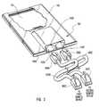
- FIG. 2is a front perspective view depicting various details of an embodiment of the present invention
- FIG. 3is a rear perspective view depicting various details of an embodiment of the present invention.
- FIG. 4is an exploded front perspective view illustrating an exemplary application of an embodiment of the present invention.
- FIG. 5is a rear perspective view of the exemplary application illustrated in FIG. 4;
- FIG. 6is a front perspective view of the exemplary application illustrated in FIG. 4.
- FIG. 7is a front end view of the exemplary application illustrated in FIG. 4 .
- FIG. 1wherein a PC card constructed in accordance with the teachings of the present invention is indicated generally at 100 .
- the illustrated cardis commonly referred to as a “combination” PC card, in that it is a PC card that incorporates a plurality of functionalities.
- One example of such a combination PC cardis one which includes both an RJ-11 and RJ-45 connector, each of which has associated therewith a particular functionality.
- the RJ-11 connectorpermits the combination PC card to communicate with remote devices via the public telephone network
- the RJ-45 connectorpermits the combination PC card to communicate with networks such as Ethernet Local Area Networks (LAN).
- LANLocal Area Networks
- the exemplary combination PC cardpossesses at least two different functionalities.
- the host device 300(such as a notebook computer) is equipped with a slot 302 that is able to functionally accommodate two adjacent PC cards having a Type II form factor, or a single PC card having a Type III form factor.
- combination PC card 100may be used either alone or contemporaneously with another complimentary PC card 200 .
- PC card 200may incorporate any of a variety of functionalities.
- PC card 200may comprise a wireless PC card which is effective in facilitating wireless communications between a host device and any of a variety of other systems and remote devices. Both combination PC card 100 and PC card 200 are configured to physically and electrically interface with a host computer 300 having one or more PC card slots 302 .
- host computer 300may conform to any of a variety of configurations including, but not limited to, a laptop computer or other type of portable computer, a standard desktop personal computer, a handheld electronic device, any device configured for use with a peripheral such as a PCMCIA device or the like.
- host computer 300includes a slot 302 having two adjacent 68 pin connectors and appropriate slots to operatively receive a PC card.
- slot 302permits for simultaneous reception of two Type II PC cards, or a single Type M card.
- embodiments of combination PC card 100 having integrated receptacles presenting a height similar to the thickness specified by the Type III standardmay be simultaneously received in PC card slot 302 with another adjacent complimentary PC card conforming, for example, to the Type II standard.
- combination PC card 100may be configured to individually and/or collectively conform to various other physical and electrical standards, form factors, and the like, as required to suit a particular application or computer hardware, and/or to facilitate achievement of one or more desired results.
- combination PC card 100facilitates the connection of host computer 300 to network 400 , and the transmission of communications therebetween.
- Network 400may comprise both wireless and hardwired remote devices or, alternatively, only hardwired devices.
- a “hardwired” device or “hardwire” connectionrefers to arrangements, connections, and. devices wherein a physical connection between computers and other devices is implemented which facilitates communication therebetween.
- a “wireless” device or “wireless” connectionrefers to arrangements, connections, and devices wherein computers and devices are able to communicate with each other by way of radio signals or the like and, accordingly, do not require a physical connection with each other. Note that additional details regarding the specific nature of the connections between host computer 300 , and network 400 and/or various remote devices, are provided below in the context of the discussion of FIGS. 2 and 3.
- network 400may comprise various types of hardwired and wireless remote devices, consistent with variables including, but not limited to, installation constraints, operational requirements of the network, cost considerations, and the like.
- network 400includes, among other things, a wireless access point 402 configured for hardwire based communication with host computer 300 .
- wireless access point 402serves to facilitate communication between host computer 300 and one or more remote devices. It will be appreciated however, that wireless access point 402 may be omitted without impairing the functionality of embodiments of the present invention.
- network 400preferably includes one or more remote computers 404 configured for wireless communication with wireless access point 402 , as well as one or more remote computers 406 and 408 either directly connected to host computer 300 , or configured and arranged for communication with host computer 300 by way of one or more intermediate remote computers. It will be appreciated that network 400 may additionally include one or more hardwired servers 410 in communication with remote computers 404 , 406 , and 408 , as well as one or more wireless servers (not shown) configured for wireless communication with wireless access point 402 and/or remote computer 404 .
- remote devicerefers to any device or system configured for communication with host computer 300 , either indirectly, such as in the case of remote computers 404 and 406 , or directly, such as in the case of wireless access point 402 and remote computer 408 .
- remote devicenot only comprehends the device, or devices, such as remote computers 404 , 406 , and 408 , which is/are the ultimate destination, or origination point, of communications, but may additionally or alternatively comprise intermediate devices, such as wireless access point 402 which, while they transmit/receive communications to/from host computer 300 and/or one or more remote devices, may not be the ultimate destination for such communications.
- embodiments of the present inventionmay be usefully employed in the context of operating environments such as network 400 , it will be appreciated that other operating environments for embodiments of the present invention are likewise appropriate.
- embodiments of the present inventionmay be used to facilitate hardwire based communication between host computer 300 and, for example, cellular, satellite, or hardwired telephones, so-called “personal data assistants” (PDA), wireless access point 402 , and a variety of other systems and devices.
- PDApersonal data assistants
- a communication initiated at host computer 300is passed to one or more remote devices of network 400 by way of combination PC card 100 and, or alternatively, a communication is initiated at one or more remote devices and transmitted to host computer 300 by way of combination PC card 100 .
- combination PC card 100acts as an interface which facilitates communication between host computer 300 and one or more remote devices.
- subject matter transmitted by way of such “communications”includes, but is not limited to, data, electronic mail, instructions, programs, files, electronic media, and any other material embodied in a form capable of being transmitted from or to host computer 300 by way of combination PC card 100 .
- communications initiated at host computer 300may be transmitted to any of a variety of remote devices.
- a communication initiated at host computer 300may be transmitted to wireless access point 402 , by way of combination PC card 100 , and then relayed by wireless access point 402 to one or more hardwired devices, such as remote computers 406 and 408 , connected to wireless access point 402 , and/or to one or more wireless remote devices such as remote computer 404 .
- communication between host computer 300 and one or more remote devices, by way of combination PC card 100may be performed in response to input provided to host computer 300 by a user, and/or may be performed automatically according to various criteria embodied in hardware and/or software associated with host computer 300 .
- communication with host computer 300may be initiated by, or at, one or more remote devices, including, but not limited to, remote computers 404 , 406 and 408 , and wireless access point 402 .
- combination PC card 100which includes, among other things, two integrated connector receptacles 102 B and 102 C, and a main housing portion 104 .
- main housing portion 104conforms to the Type II PCMCIA standards for length and width.
- Housing 104includes, among other things, front edge 104 A.
- connector. receptacle 102is formed as a single, integrally formed connector body housing 102 A that at least partially defines receptacles 102 B and 102 C.
- connector body 102 Ais formed as an integral piece with main housing 104 portion of combination PC card 100 .
- connector body 102 Amay, alternatively, constitute a structure distinct from housing 104 .
- connector body 102 Amay comprise two distinct portions, one such portion at least partially defining receptacle 102 B, and another such portion at least partially defining receptacle 102 C.
- receptacle 102 B of connector 102is configured to removably receive an RJ-11 type communications plug 500 A that is connected to a communications wire, 500 B which includes another plug 500 C configured to physically and electrically interface with the public telephone network.
- Receptacle 102 Cis configured to removably receive an RJ-45 type communications plug 500 D that is connected to a communications wire 500 E which includes another communications plug 500 E configured to physically and electrically interface with a local area network medium (not shown).
- combination PC card 100include one or more RJ-type connectors configured to physically and electrically interface with RJ-type communication plugs
- connectors 102may comprise any of a variety of arrangements configured to provide a physical and electrical interface between combination PC card 100 , and thus host computer 300 , and one or more remote devices.
- one or more of connectors 102may alternatively comprise a coaxial connection, a cell phone interface, a PDA interface, or one of the various types of multisocket connectors configured to receive a multi-pin plug.
- variables including, but not limited to, the size, shape, type, and number of connectors 102may be varied, either alone or in various combinations, as required to suit particular applications and/or to facilitate achievement of one or more desired results.
- connectors 102may be modified as required to produce embodiments of combination PC card 100 that possess a geometry that is sensitive to particular geometric constraints or requirements of another complimentary PC card which is desired to be used simultaneously with combination PC card 100 in PC card slot 302 of host computer 300 (see FIG. 1 ). Further details regarding one exemplary arrangement are provided below in the context of the discussion of FIGS. 4, 5 , and 6 .
- combination PC card 100additionally includes electronic circuitry 106 disposed substantially within housing 104 , and in electrical communication with connectors 102 .
- electronic circuitry 106comprises circuits, devices, wiring, processors, integrated circuits, indicators, and the like, necessary to implement the functionality of combination PC card 100 .
- electronic circuitry 106comprises an analog modem and a network interface circuit.
- combination PC card 100further includes connector 108 , preferably comprising a PCMCIA standard 68socket configuration, which serves to physically connect combination PC card 100 to a mating connector in PC card slot 302 of host computer 300 , as well as to electrically connect electronic circuitry 106 to host computer 300 .
- connector 108may take any of a variety of other forms as may be required for consistency and compatibility with the configuration of host computer 300 , PC card slot 302 , other hardware, and/or applicable electrical power constraints. Accordingly, the scope of the present invention should not be construed to be limited solely to standard 68socket connectors.
- connector 108is but one example of a means for physically and electrically connecting combination PC card 100 to host computer 300 . It should be understood that the embodiment of connector 108 is presented herein solely by way of example and should not be construed as limiting the scope of the present invention in any way.
- a means for physically and electrically connecting combination PC card 100 to host computer 300includes within its purview, arrangements comprising one structure for electrically connecting combination PC card 100 to host computer 300 , such as a plurality of electrical contacts arranged for sliding surface engagement with mating contacts in PC card slot 302 , and a separate structure for physically connecting combination PC card 100 to host computer 300 , such as locking tabs or the like.
- connector body housing 102 A and connectors 102are preferably arranged and configured so as to define a geometry sensitive to the geometric and operational requirements of other PC cards which are desired to be used in PC card slot 302 contemporaneously with combination PC card 100 .
- FIGS. 4 through 7, and with continuing reference to FIGS. 2 and 3, one exemplary arrangement of connectors 102is indicated.
- connector body 102 Ais positioned at the center of front edge 104 A of housing 104 of combination PC card 100 so as to comport with the split antenna geometry of a complimentary wireless PC card 200 A.
- the shape and positioning of the integrated receptaclesthus facilitate contemporaneous use of wireless PC card 200 A in an adjacent PC card slot 302 , notwithstanding the fact that the full height profile of the receptacles would otherwise block access to the adjacent slot.
- connector body 102 Ais configured and arranged so as to be at least partially received in the recess portion 202 A defined by the housing of wireless PC card 200 A.
- wireless PC card 200 Aconforms substantially to the PCMCIA Type II form factor.
- Combination PC card 100due to the presence of connectors 102 conforming to RJ-type standards, at least partially comports substantially with the Type III form factor—at least with respect to the thickness presented via the integrated receptacles.
- combination PC card 100 and wireless PC card 200 Acollectively conform to the Type III form factor. Accordingly, it is a feature of embodiments of the present invention that the simultaneous use of a Type II PC card and a Type III PC card in adjacent 68pin connectors is made possible.
- combination PC card 100is characterized by a geometry that facilitates the antenna separation that is required for optimum performance of wireless PC card 200 A.
- the positioning of connector body housing 102 A of combination PC card 100is consistent with the requirement, typical of wireless PC cards, that the antennae of such wireless PC cards be separated to the maximum extent practicable in order to better facilitate optimal operation of the wireless PC card. That is, the geometry of the illustrated embodiment of combination PC card permits the simultaneous use of wireless PC cards having a geometry directed toward maximizing the distance between antennae disposed in such wireless PC card.
- combination PC card 100has a geometry which makes it well suited for contemporaneous use with a wireless PC card 200 A
- various other embodiments of combination PC card 100may be employed that are suitable for use with other PC cards 200 having different geometries, operational requirements, and functionalities.
- the complimentary portion of the PC card 100could present other geometries so as to comport with the shape of an adjacent card.
- the connector body housing 102 Acould include slots and/or rails, designed to provide a mechanical fit with portions of the adjacent card 200 A. Other locking and/or guiding mechanisms could also be used, to provide functional fit between the adjacent cards.
- combination PC card 100Another feature relating to the operational flexibility facilitated by embodiments. of combination PC card 100 concerns the interaction between combination PC card 100 and, for example, wireless PC card 200 A when it is desired to remove and/or replace wireless PC card 200 A from PC card slot 302 .
- connector body housing 102 A of combination PC card 100is configured and arranged to be removably received within the recess 202 A defined by wireless PC card 200 A. Consequently, combination PC card 100 can be readily removed and replaced without also necessitating the removal of wireless PC card 200 A from PC card slot 302 .
- This featureserves to enhance the operational flexibility of host computer 300 by permitting removal and/or replacement of combination PC card 100 without compromising the integrity of the wireless connection implemented by way of wireless PC card 200 A.
- the present inventionrepresents an improvement over known combination PC cards, typically characterized by various geometric features that impose operational or other restrictions on PC cards used contemporaneously in adjacent PC card slots.
- embodiments of the present inventionallow two cards to reside in adjacent slots, even though one of the cards presents a form factor that would otherwise prevent the use of another adjacent card.
- the presence of connector receptacles, full height RJ-type connectorspermits combination PC card 100 to be used to facilitate communication between host computer 300 and various remote devices.
- the connectors 102are configured and arranged in a manner that is sensitive to the specific geometric requirements of other PC cards, such as a wireless PC card which are desired to be used contemporaneously with combination PC card 100 in an adjacent PC card slot.
- the connectorsare configured and arranged to permit removal of combination PC card 100 from PC card slot 302 , without also necessitating the removal of the other PC card residing in the adjacent PC card slot.
Landscapes
- Engineering & Computer Science (AREA)
- Computer Networks & Wireless Communication (AREA)
- Signal Processing (AREA)
- Computer Security & Cryptography (AREA)
- Microelectronics & Electronic Packaging (AREA)
- Credit Cards Or The Like (AREA)
- Coupling Device And Connection With Printed Circuit (AREA)
Abstract
Description
Claims (36)
Priority Applications (1)
| Application Number | Priority Date | Filing Date | Title |
|---|---|---|---|
| US09/795,505US6447306B1 (en) | 2001-02-28 | 2001-02-28 | PC card configuration |
Applications Claiming Priority (1)
| Application Number | Priority Date | Filing Date | Title |
|---|---|---|---|
| US09/795,505US6447306B1 (en) | 2001-02-28 | 2001-02-28 | PC card configuration |
Publications (2)
| Publication Number | Publication Date |
|---|---|
| US20020119683A1 US20020119683A1 (en) | 2002-08-29 |
| US6447306B1true US6447306B1 (en) | 2002-09-10 |
Family
ID=25165689
Family Applications (1)
| Application Number | Title | Priority Date | Filing Date |
|---|---|---|---|
| US09/795,505Expired - Fee RelatedUS6447306B1 (en) | 2001-02-28 | 2001-02-28 | PC card configuration |
Country Status (1)
| Country | Link |
|---|---|
| US (1) | US6447306B1 (en) |
Cited By (3)
| Publication number | Priority date | Publication date | Assignee | Title |
|---|---|---|---|---|
| US6839229B2 (en)* | 2001-09-07 | 2005-01-04 | Fujitsu Limited | Information processing device and external unit |
| USD591754S1 (en)* | 2008-07-15 | 2009-05-05 | Samsung Electronics Co., Ltd. | Memory card |
| USD607885S1 (en)* | 2007-05-17 | 2010-01-12 | Kyocera Corporation | PC card adapter |
Families Citing this family (6)
| Publication number | Priority date | Publication date | Assignee | Title |
|---|---|---|---|---|
| FR2841716B1 (en)* | 2002-06-28 | 2005-02-04 | Thomson Licensing Sa | METHOD OF CREATING A NEW COMMUNICATION NETWORK BY A WIRELESS TERMINAL AND TERMINAL USING THE METHOD |
| US7444207B2 (en) | 2002-10-15 | 2008-10-28 | Rain Bird Corporation | Modular and expandable irrigation controller |
| EP1769298A4 (en)* | 2003-12-23 | 2011-11-23 | Rain Bird Corp | Modular and expandable irrigation controller |
| US7844367B2 (en) | 2003-12-23 | 2010-11-30 | Rain Bird Corporation | Code replacement for irrigation controllers |
| DE102006013944B3 (en)* | 2006-03-27 | 2007-11-08 | Vector Informatik Gmbh | Coupling device with pluggable module for coupling a diagnostic device |
| EP3438676B1 (en)* | 2017-08-04 | 2020-07-15 | Rohde & Schwarz GmbH & Co. KG | Modular device architecture |
Citations (59)
| Publication number | Priority date | Publication date | Assignee | Title |
|---|---|---|---|---|
| US2916720A (en) | 1957-08-14 | 1959-12-08 | Robert B Steans | Electrical connector |
| US3205471A (en) | 1962-12-05 | 1965-09-07 | Adolf L Herrmann | Electrical connector for a pair of circuit boards |
| US4186988A (en) | 1978-09-20 | 1980-02-05 | Amp Incorporated | Electrical connector receptacles |
| US4239316A (en) | 1978-05-03 | 1980-12-16 | Bunker Ramo Corporation | Electrical connectors and assemblies therefor |
| US4241974A (en) | 1979-05-02 | 1980-12-30 | Western Electric Company, Inc. | Multi-outlet adapter for modular telephone cords |
| US4303296A (en) | 1978-05-03 | 1981-12-01 | Bunker Ramo Corporation | Modular interface connector |
| US4352492A (en) | 1976-08-23 | 1982-10-05 | Fairchild Camera & Instrument Corp. | Data storage apparatus |
| US4407559A (en) | 1981-04-09 | 1983-10-04 | Communications Systems, Inc. | Connector device with flush mounting receptacle, cover plate and terminal board |
| US4428636A (en) | 1981-11-05 | 1984-01-31 | Amp Incorporated | Multi-contact connectors for closely spaced conductors |
| US4566749A (en) | 1984-08-09 | 1986-01-28 | Brand-Rex Company | Electrical connector receptacle |
| US4602842A (en) | 1984-12-03 | 1986-07-29 | Cts Corporation | Electrical connector receptacle |
| JPS61256850A (en) | 1985-05-08 | 1986-11-14 | Fujitsu Ltd | Preventing plug for radio wave of telephone set |
| US4647136A (en) | 1984-03-07 | 1987-03-03 | Mitsumi-Cinch, Ltd. | Modular plug and printed circuit connector |
| US4710136A (en) | 1982-02-26 | 1987-12-01 | Nippon Electric Co., Ltd. | Mounting structure for electronic apparatus or the like |
| US4778410A (en) | 1986-09-22 | 1988-10-18 | Hosiden Electronics Co., Ltd. | Jack |
| US4875872A (en) | 1987-11-04 | 1989-10-24 | Hosiden Electronics Co., Ltd. | Telephone connector |
| US4915648A (en) | 1988-03-04 | 1990-04-10 | Fuji Jukogyo Kabushiki Kaisha | Connector with a lock mechanism |
| US4934947A (en) | 1987-10-30 | 1990-06-19 | Amp Incorporated | Modular jack for flat flexible cable |
| US5035641A (en) | 1988-02-15 | 1991-07-30 | Itt Industries Limited | Terminating insulated conductors |
| US5051099A (en) | 1990-01-10 | 1991-09-24 | Amp Incorporated | High speed card edge connector |
| US5139439A (en) | 1991-07-16 | 1992-08-18 | Veridata Electronics Inc. | Portable computer with detachable cartridge type interface device |
| US5183404A (en) | 1992-04-08 | 1993-02-02 | Megahertz Corporation | Systems for connection of physical/electrical media connectors to computer communications cards |
| US5184282A (en) | 1989-02-27 | 1993-02-02 | Mips Co., Ltd. | IC card adapter |
| US5310360A (en) | 1993-05-18 | 1994-05-10 | Molex Incorporated | Circuit board mounted modular phone jack |
| US5364294A (en) | 1991-12-24 | 1994-11-15 | Stewart Connector Systems, Inc. | Electrical device for surface mounting on a circuit board and mounting component thereof |
| US5391094A (en) | 1992-11-20 | 1995-02-21 | Murata Mfg. Co., Ltd. | Card-type line interface device |
| US5391083A (en) | 1994-02-25 | 1995-02-21 | R. A. Tool & Die, Inc. | Computer card connector |
| US5411405A (en) | 1993-11-12 | 1995-05-02 | Angia Communications, Inc. | Miniature electrical communications connectors |
| US5425660A (en) | 1993-12-22 | 1995-06-20 | Communications System, Inc. | Communications jack with improved comb |
| US5457601A (en) | 1993-12-08 | 1995-10-10 | At&T Corp. | Credit card-sized modem with modular DAA |
| US5478261A (en) | 1978-06-14 | 1995-12-26 | Virginia Patent Development Corp. | Modular jack for directly coupling modular plug with printed circuit board |
| US5481616A (en) | 1993-11-08 | 1996-01-02 | Sparkomatic Corporation | Plug-in sound accessory for portable computers |
| US5499923A (en) | 1994-11-09 | 1996-03-19 | At&T Corp. | Communication card with extendible, rotatable coupling |
| US5505633A (en) | 1994-05-13 | 1996-04-09 | Intel Corporation | Integral external connector interface for thin form factor computer cards |
| US5509811A (en) | 1994-01-12 | 1996-04-23 | Dell Usa, L.P. | Computer enclosure with embedded PCMCIA modem card |
| US5538442A (en) | 1993-10-04 | 1996-07-23 | Murata Mfg. Co., Ltd. | Communication card |
| US5547401A (en) | 1992-04-08 | 1996-08-20 | Megahertz Corporation | Media connector interface for use with a thin-architecture communications card |
| US5561727A (en) | 1994-02-15 | 1996-10-01 | Sumitomo Electric Industries, Ltd. | Card-shaped optical data link device |
| US5562504A (en) | 1995-01-04 | 1996-10-08 | Simple Technology Incorporated | Communications card with integral transmission media line adaptor |
| US5580274A (en) | 1993-02-23 | 1996-12-03 | Tsair; Chwan-Tsay | Modular jack structure |
| US5608607A (en) | 1995-04-24 | 1997-03-04 | Compaq Computer Corporation | PCMCIA card and associated support and circuitry augmenting apparatus and methods |
| US5634802A (en) | 1994-08-18 | 1997-06-03 | International Business Machines Corporation | Retractable expandable jack |
| US5660568A (en) | 1995-01-04 | 1997-08-26 | Simple Technology, Inc. | Communications card with integral transmission media line adaptor |
| US5667390A (en) | 1995-03-06 | 1997-09-16 | Hon Hai Precision Ind. Co., Ltd. | I/O card and its associated cable harness assembly |
| US5679013A (en) | 1994-11-14 | 1997-10-21 | International Business Machines Corporation | Electrical connector and an electronic apparatus using the electrical connector |
| US5697815A (en) | 1995-06-07 | 1997-12-16 | Drewnicki; Richard | Electrical connectors |
| US5773332A (en) | 1993-11-12 | 1998-06-30 | Xircom, Inc. | Adaptable communications connectors |
| US5797771A (en) | 1996-08-16 | 1998-08-25 | U.S. Robotics Mobile Communication Corp. | Cable connector |
| US5816832A (en) | 1992-04-08 | 1998-10-06 | 3Com Corporation | Media connector interface for use with a PCMCIA-architecture communications card |
| US5876218A (en) | 1997-05-28 | 1999-03-02 | Gateway 2000, Inc. | Piggy back PC card |
| US5980322A (en) | 1998-09-01 | 1999-11-09 | 3Com Corporation | Electrical connector having a fusible link for use between media connectors and computer communications cards |
| US5984731A (en) | 1997-11-17 | 1999-11-16 | Xircom, Inc. | Removable I/O device with integrated receptacles for receiving standard plugs |
| US5989042A (en) | 1998-04-03 | 1999-11-23 | 23-3178 | Electrical connector for use between shielded media connectors and computer communications cards |
| US6005774A (en) | 1994-12-09 | 1999-12-21 | International Business Machines Corporation | Integrated circuit card |
| US6033240A (en) | 1998-10-30 | 2000-03-07 | 3Com Corporation | Retractable media jack operable with two discrete media connectors |
| US6116962A (en) | 1997-11-17 | 2000-09-12 | Xircom Inc | Type III PCMCIA card with integrated receptacles for receiving standard communications plugs |
| US6183307B1 (en)* | 1997-11-17 | 2001-02-06 | Xircom, Inc. | PC cards with integrated I/O communication receptacles |
| US6217391B1 (en) | 1998-03-26 | 2001-04-17 | Stewart Connector Systems, Inc. | Low profile modular electrical jack and communication card including the same |
| US6341069B1 (en)* | 1996-11-04 | 2002-01-22 | Alcatel | Radio modem fitted with a memory card reader |
- 2001
- 2001-02-28USUS09/795,505patent/US6447306B1/ennot_activeExpired - Fee Related
Patent Citations (64)
| Publication number | Priority date | Publication date | Assignee | Title |
|---|---|---|---|---|
| US2916720A (en) | 1957-08-14 | 1959-12-08 | Robert B Steans | Electrical connector |
| US3205471A (en) | 1962-12-05 | 1965-09-07 | Adolf L Herrmann | Electrical connector for a pair of circuit boards |
| US4352492A (en) | 1976-08-23 | 1982-10-05 | Fairchild Camera & Instrument Corp. | Data storage apparatus |
| US4239316A (en) | 1978-05-03 | 1980-12-16 | Bunker Ramo Corporation | Electrical connectors and assemblies therefor |
| US4303296A (en) | 1978-05-03 | 1981-12-01 | Bunker Ramo Corporation | Modular interface connector |
| US5478261A (en) | 1978-06-14 | 1995-12-26 | Virginia Patent Development Corp. | Modular jack for directly coupling modular plug with printed circuit board |
| US4186988A (en) | 1978-09-20 | 1980-02-05 | Amp Incorporated | Electrical connector receptacles |
| US4241974A (en) | 1979-05-02 | 1980-12-30 | Western Electric Company, Inc. | Multi-outlet adapter for modular telephone cords |
| US4407559A (en) | 1981-04-09 | 1983-10-04 | Communications Systems, Inc. | Connector device with flush mounting receptacle, cover plate and terminal board |
| US4428636A (en) | 1981-11-05 | 1984-01-31 | Amp Incorporated | Multi-contact connectors for closely spaced conductors |
| US4710136A (en) | 1982-02-26 | 1987-12-01 | Nippon Electric Co., Ltd. | Mounting structure for electronic apparatus or the like |
| US4647136A (en) | 1984-03-07 | 1987-03-03 | Mitsumi-Cinch, Ltd. | Modular plug and printed circuit connector |
| US4566749A (en) | 1984-08-09 | 1986-01-28 | Brand-Rex Company | Electrical connector receptacle |
| US4602842A (en) | 1984-12-03 | 1986-07-29 | Cts Corporation | Electrical connector receptacle |
| JPS61256850A (en) | 1985-05-08 | 1986-11-14 | Fujitsu Ltd | Preventing plug for radio wave of telephone set |
| US4778410A (en) | 1986-09-22 | 1988-10-18 | Hosiden Electronics Co., Ltd. | Jack |
| US4934947A (en) | 1987-10-30 | 1990-06-19 | Amp Incorporated | Modular jack for flat flexible cable |
| US4875872A (en) | 1987-11-04 | 1989-10-24 | Hosiden Electronics Co., Ltd. | Telephone connector |
| US5035641A (en) | 1988-02-15 | 1991-07-30 | Itt Industries Limited | Terminating insulated conductors |
| US4915648A (en) | 1988-03-04 | 1990-04-10 | Fuji Jukogyo Kabushiki Kaisha | Connector with a lock mechanism |
| US5184282A (en) | 1989-02-27 | 1993-02-02 | Mips Co., Ltd. | IC card adapter |
| US5051099A (en) | 1990-01-10 | 1991-09-24 | Amp Incorporated | High speed card edge connector |
| US5139439A (en) | 1991-07-16 | 1992-08-18 | Veridata Electronics Inc. | Portable computer with detachable cartridge type interface device |
| US5364294A (en) | 1991-12-24 | 1994-11-15 | Stewart Connector Systems, Inc. | Electrical device for surface mounting on a circuit board and mounting component thereof |
| US5816832A (en) | 1992-04-08 | 1998-10-06 | 3Com Corporation | Media connector interface for use with a PCMCIA-architecture communications card |
| US5183404A (en) | 1992-04-08 | 1993-02-02 | Megahertz Corporation | Systems for connection of physical/electrical media connectors to computer communications cards |
| US5336099A (en) | 1992-04-08 | 1994-08-09 | Megahertz Corporation | Media connector interface for use with a PCMCIA-architecture communications card |
| US5338210A (en) | 1992-04-08 | 1994-08-16 | Megahertz Corporation | Media connector interface for use with a PCMCIA-architecture communications card |
| US5727972A (en) | 1992-04-08 | 1998-03-17 | Aldous; Stephen C. | Media connector interface for use with a thin-architecture communications card |
| US5938480A (en) | 1992-04-08 | 1999-08-17 | 3Com Corporation | Media connector interface for use with electrical apparatus |
| US5547401A (en) | 1992-04-08 | 1996-08-20 | Megahertz Corporation | Media connector interface for use with a thin-architecture communications card |
| US5391094A (en) | 1992-11-20 | 1995-02-21 | Murata Mfg. Co., Ltd. | Card-type line interface device |
| US5580274A (en) | 1993-02-23 | 1996-12-03 | Tsair; Chwan-Tsay | Modular jack structure |
| US5310360A (en) | 1993-05-18 | 1994-05-10 | Molex Incorporated | Circuit board mounted modular phone jack |
| US5538442A (en) | 1993-10-04 | 1996-07-23 | Murata Mfg. Co., Ltd. | Communication card |
| US5481616A (en) | 1993-11-08 | 1996-01-02 | Sparkomatic Corporation | Plug-in sound accessory for portable computers |
| US5773332A (en) | 1993-11-12 | 1998-06-30 | Xircom, Inc. | Adaptable communications connectors |
| WO1995013633A1 (en) | 1993-11-12 | 1995-05-18 | Angia Communications, Inc. | Adaptable communications connectors |
| US5411405A (en) | 1993-11-12 | 1995-05-02 | Angia Communications, Inc. | Miniature electrical communications connectors |
| US5457601A (en) | 1993-12-08 | 1995-10-10 | At&T Corp. | Credit card-sized modem with modular DAA |
| US5425660A (en) | 1993-12-22 | 1995-06-20 | Communications System, Inc. | Communications jack with improved comb |
| US5509811A (en) | 1994-01-12 | 1996-04-23 | Dell Usa, L.P. | Computer enclosure with embedded PCMCIA modem card |
| US5561727A (en) | 1994-02-15 | 1996-10-01 | Sumitomo Electric Industries, Ltd. | Card-shaped optical data link device |
| US5391083A (en) | 1994-02-25 | 1995-02-21 | R. A. Tool & Die, Inc. | Computer card connector |
| US5505633A (en) | 1994-05-13 | 1996-04-09 | Intel Corporation | Integral external connector interface for thin form factor computer cards |
| US5634802A (en) | 1994-08-18 | 1997-06-03 | International Business Machines Corporation | Retractable expandable jack |
| US5499923A (en) | 1994-11-09 | 1996-03-19 | At&T Corp. | Communication card with extendible, rotatable coupling |
| US5679013A (en) | 1994-11-14 | 1997-10-21 | International Business Machines Corporation | Electrical connector and an electronic apparatus using the electrical connector |
| US6005774A (en) | 1994-12-09 | 1999-12-21 | International Business Machines Corporation | Integrated circuit card |
| US5562504A (en) | 1995-01-04 | 1996-10-08 | Simple Technology Incorporated | Communications card with integral transmission media line adaptor |
| US5660568A (en) | 1995-01-04 | 1997-08-26 | Simple Technology, Inc. | Communications card with integral transmission media line adaptor |
| US5667390A (en) | 1995-03-06 | 1997-09-16 | Hon Hai Precision Ind. Co., Ltd. | I/O card and its associated cable harness assembly |
| US5608607A (en) | 1995-04-24 | 1997-03-04 | Compaq Computer Corporation | PCMCIA card and associated support and circuitry augmenting apparatus and methods |
| US5697815A (en) | 1995-06-07 | 1997-12-16 | Drewnicki; Richard | Electrical connectors |
| US5797771A (en) | 1996-08-16 | 1998-08-25 | U.S. Robotics Mobile Communication Corp. | Cable connector |
| US6341069B1 (en)* | 1996-11-04 | 2002-01-22 | Alcatel | Radio modem fitted with a memory card reader |
| US5876218A (en) | 1997-05-28 | 1999-03-02 | Gateway 2000, Inc. | Piggy back PC card |
| US5984731A (en) | 1997-11-17 | 1999-11-16 | Xircom, Inc. | Removable I/O device with integrated receptacles for receiving standard plugs |
| US6116962A (en) | 1997-11-17 | 2000-09-12 | Xircom Inc | Type III PCMCIA card with integrated receptacles for receiving standard communications plugs |
| US6183307B1 (en)* | 1997-11-17 | 2001-02-06 | Xircom, Inc. | PC cards with integrated I/O communication receptacles |
| US6217391B1 (en) | 1998-03-26 | 2001-04-17 | Stewart Connector Systems, Inc. | Low profile modular electrical jack and communication card including the same |
| US5989042A (en) | 1998-04-03 | 1999-11-23 | 23-3178 | Electrical connector for use between shielded media connectors and computer communications cards |
| US5980322A (en) | 1998-09-01 | 1999-11-09 | 3Com Corporation | Electrical connector having a fusible link for use between media connectors and computer communications cards |
| US6033240A (en) | 1998-10-30 | 2000-03-07 | 3Com Corporation | Retractable media jack operable with two discrete media connectors |
Non-Patent Citations (1)
| Title |
|---|
| P.E. Knight and D.R. Smith, "Electrical Connector for Flat Flexible Cable," IBM Technical Disclosure Bulletin, vol. 25, No. 1, Jun. 1982. |
Cited By (3)
| Publication number | Priority date | Publication date | Assignee | Title |
|---|---|---|---|---|
| US6839229B2 (en)* | 2001-09-07 | 2005-01-04 | Fujitsu Limited | Information processing device and external unit |
| USD607885S1 (en)* | 2007-05-17 | 2010-01-12 | Kyocera Corporation | PC card adapter |
| USD591754S1 (en)* | 2008-07-15 | 2009-05-05 | Samsung Electronics Co., Ltd. | Memory card |
Also Published As
| Publication number | Publication date |
|---|---|
| US20020119683A1 (en) | 2002-08-29 |
Similar Documents
| Publication | Publication Date | Title |
|---|---|---|
| US6577500B2 (en) | Wireless PC card | |
| US5608606A (en) | Computer plug-in module and interconnection system for wireless applications | |
| US8326347B2 (en) | Wireless communication system integrated into a computer display | |
| US5642259A (en) | Arrangement for connecting an expansion card to a connector socket in a personal computer | |
| EP0811186B1 (en) | Modular pcmcia card | |
| CN1063601C (en) | Modular radio communications system | |
| US5505633A (en) | Integral external connector interface for thin form factor computer cards | |
| US7540786B1 (en) | Flash memory device with improved contact arrangement | |
| US6190182B1 (en) | Piggy back PC card | |
| US5445525A (en) | Interconnection scheme for integrated circuit card with auxiliary contacts | |
| US6542358B1 (en) | Retractable platform with wireless electrical interface | |
| US6547602B2 (en) | Modular plug receptacles defined by multiple electronic components | |
| EP1057225B1 (en) | Compliant communications connectors | |
| US5989042A (en) | Electrical connector for use between shielded media connectors and computer communications cards | |
| US6137679A (en) | Multi-bus mobile hard disk drive rack | |
| KR20030051636A (en) | Cooperative interconnection and operation of a non-volatile memory card and an input-output card | |
| US6447306B1 (en) | PC card configuration | |
| US7988460B1 (en) | Electrical engagement structure of connection device | |
| US6469681B2 (en) | Removable antenna for connection to miniature modular jacks | |
| US6461170B1 (en) | Stacked electronic integrated card assembly with multi-function shared interface | |
| EP1125368B1 (en) | Battery case for pcmcia card modem with antenna | |
| US6475003B2 (en) | Physically independent connector for retractable and removeable extensions in thin-profile electronic devices | |
| US20030148639A1 (en) | Connection-converting device for an expansion card in a portable electronic product | |
| US6141212A (en) | Method and apparatus for connecting peripherals having various size plugs and functions | |
| US6456496B1 (en) | Type III pccard system with full wall modular extendable RJ45/11 connector |
Legal Events
| Date | Code | Title | Description |
|---|---|---|---|
| FPAY | Fee payment | Year of fee payment:4 | |
| FPAY | Fee payment | Year of fee payment:8 | |
| AS | Assignment | Owner name:HEWLETT-PACKARD COMPANY, CALIFORNIA Free format text:MERGER;ASSIGNOR:3COM CORPORATION;REEL/FRAME:024630/0820 Effective date:20100428 | |
| AS | Assignment | Owner name:HEWLETT-PACKARD COMPANY, CALIFORNIA Free format text:CORRECTIVE ASSIGNMENT TO CORRECT THE SEE ATTACHED;ASSIGNOR:3COM CORPORATION;REEL/FRAME:025039/0844 Effective date:20100428 | |
| AS | Assignment | Owner name:HEWLETT-PACKARD DEVELOPMENT COMPANY, L.P., TEXAS Free format text:ASSIGNMENT OF ASSIGNORS INTEREST;ASSIGNOR:HEWLETT-PACKARD COMPANY;REEL/FRAME:027329/0044 Effective date:20030131 | |
| AS | Assignment | Owner name:HEWLETT-PACKARD DEVELOPMENT COMPANY, L.P., TEXAS Free format text:CORRECTIVE ASSIGNMENT PREVIUOSLY RECORDED ON REEL 027329 FRAME 0001 AND 0044;ASSIGNOR:HEWLETT-PACKARD COMPANY;REEL/FRAME:028911/0846 Effective date:20111010 | |
| REMI | Maintenance fee reminder mailed | ||
| LAPS | Lapse for failure to pay maintenance fees | ||
| STCH | Information on status: patent discontinuation | Free format text:PATENT EXPIRED DUE TO NONPAYMENT OF MAINTENANCE FEES UNDER 37 CFR 1.362 | |
| FP | Lapsed due to failure to pay maintenance fee | Effective date:20140910 |