US6447216B1 - Fluid pumping system for particulate material - Google Patents
Fluid pumping system for particulate materialDownload PDFInfo
- Publication number
- US6447216B1 US6447216B1US09/640,051US64005100AUS6447216B1US 6447216 B1US6447216 B1US 6447216B1US 64005100 AUS64005100 AUS 64005100AUS 6447216 B1US6447216 B1US 6447216B1
- Authority
- US
- United States
- Prior art keywords
- fluid
- pumping
- particulate material
- chamber
- assembly
- Prior art date
- Legal status (The legal status is an assumption and is not a legal conclusion. Google has not performed a legal analysis and makes no representation as to the accuracy of the status listed.)
- Expired - Fee Related, expires
Links
Images


Classifications
- F—MECHANICAL ENGINEERING; LIGHTING; HEATING; WEAPONS; BLASTING
- F04—POSITIVE - DISPLACEMENT MACHINES FOR LIQUIDS; PUMPS FOR LIQUIDS OR ELASTIC FLUIDS
- F04B—POSITIVE-DISPLACEMENT MACHINES FOR LIQUIDS; PUMPS
- F04B43/00—Machines, pumps, or pumping installations having flexible working members
- F04B43/02—Machines, pumps, or pumping installations having flexible working members having plate-like flexible members, e.g. diaphragms
- F04B43/06—Pumps having fluid drive
- F04B43/073—Pumps having fluid drive the actuating fluid being controlled by at least one valve
- F04B43/0736—Pumps having fluid drive the actuating fluid being controlled by at least one valve with two or more pumping chambers in parallel
- F—MECHANICAL ENGINEERING; LIGHTING; HEATING; WEAPONS; BLASTING
- F04—POSITIVE - DISPLACEMENT MACHINES FOR LIQUIDS; PUMPS FOR LIQUIDS OR ELASTIC FLUIDS
- F04B—POSITIVE-DISPLACEMENT MACHINES FOR LIQUIDS; PUMPS
- F04B15/00—Pumps adapted to handle specific fluids, e.g. by selection of specific materials for pumps or pump parts
- F04B15/02—Pumps adapted to handle specific fluids, e.g. by selection of specific materials for pumps or pump parts the fluids being viscous or non-homogeneous
- B—PERFORMING OPERATIONS; TRANSPORTING
- B05—SPRAYING OR ATOMISING IN GENERAL; APPLYING FLUENT MATERIALS TO SURFACES, IN GENERAL
- B05B—SPRAYING APPARATUS; ATOMISING APPARATUS; NOZZLES
- B05B7/00—Spraying apparatus for discharge of liquids or other fluent materials from two or more sources, e.g. of liquid and air, of powder and gas
- B05B7/14—Spraying apparatus for discharge of liquids or other fluent materials from two or more sources, e.g. of liquid and air, of powder and gas designed for spraying particulate materials
- B05B7/1404—Arrangements for supplying particulate material
- B05B7/1459—Arrangements for supplying particulate material comprising a chamber, inlet and outlet valves upstream and downstream the chamber and means for alternately sucking particulate material into and removing particulate material from the chamber through the valves
Definitions
- the present inventionrelates to particulate material handling systems, and more particularly to such a fluid pumping system for pumping particulate material at an optimized capacity.
- Particulate material handling and processing systemssuch as powder material handling systems
- powder material handling systemstypically include the unloading, conveyance and feeding, for example, of powder material from a supply source to an output location.
- unloading, conveyance and feedingusually include use of a pneumatic pump as disclosed for example in U.S. Pat. No. 5,518,344.
- a typical powder material conveyance or conveying systemalso includes a hollow line or conduit having intake and discharge ports across which there is often a need to regulate not only the rate of powder material flow, but also the state or condition of the powder material where powder material can undesirably pack.
- purging fluid or airstays on continuously so as to dilute the particulate material being pumped.
- purging fluid or airhas been found to reduce the rate, and hence the amount, of particulate material being loaded to be pumped. This of course results in an undesirable loss of system throughput capacity.
- the systemsuffers significant disadvantages if it is necessary for some reason to substantially cut down on or reduce the level of the motive air.
- the conveying capacity of the systemusually is slowed down. If there is not sufficient purging fluid or air present, it undesirably causes particulate material to pack not only in the conveying conduits, but also in the diaphragm pump housing itself, thereby undesirably causing the pump to become significantly inefficient even to the point it stops.
- a fluid pumping assembly for pumping particulate materialincludes a pump housing defining a pump cavity including a pumping chamber for handling particulate material, a motive fluid chamber, and a moveable diaphragm
- the fluid pumping assemblyalso includes devices for loading particulate material into the pumping chamber, and for injecting a high pressure, high volume purging fluid into the pumping chamber.
- the fluid pumping assemblyincludes a control system having a control valve for shutting off flow of high pressure, high volume purging fluid into the pumping chamber when particulate material is being loaded into the pumping chamber, thus enabling dense phase loading of particulate material, and thereby optimizing a particulate material pumping capacity of the fluid pumping assembly.
- FIG. 1is a schematic illustration of a first or purging stroke of a fluid pumping assembly of the pumping system of the present invention
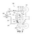
- FIG. 2is a schematic illustration of a second or return stroke of the fluid pumping assembly of FIG. 1;
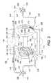
- FIG. 3is a schematic illustration of the pumping system of the present invention showing first and second pumping assemblies, a first stroke of the first pumping assembly, and a second stroke of the second pumping assembly in accordance with the present invention
- FIG. 4is a schematic illustration of the pumping system of the present invention showing the first and second pumping assemblies, a second stroke of the first pumping assembly, and a first stroke of the second pumping assembly in accordance with the present invention.
- a fluid pumping assembly 100 in accordance with the present inventionis illustrated, and is suitable for pumping particulate material, such as a powder material.
- the fluid pumping assembly 100features two pumping strokes, a first or purging stroke (FIG. 1 ), and a second or return stroke (FIG. 2 ).
- the pumping assembly 100includes a pump housing 102 that defines a pumping chamber 106 for handling particulate material 112 , a motive fluid chamber 108 , and a moveable diaphragm 110 between the pumping chamber 106 and the motive fluid chamber 108 .
- First means 111 for loading particulate material 112 into the pumping chamberinclude a material inlet 114 into the pumping chamber 106 and a conduit 115 connecting the material inlet 114 to a controllable source 116 of moving dense phase particulate material 112 .
- a second means 118including a source 120 (arrow) of high-volume, high pressure purging fluid, a purging fluid conduit 122 , and a purging fluid inlet 124 into the pumping chamber 106 , are provided for injecting high pressure, high volume purging fluid 126 into the pumping chamber 106 .
- a source 120arrow
- purging fluid conduit 122a purging fluid conduit 122 , and a purging fluid inlet 124 into the pumping chamber 106
- injecting high pressure, high volume purging fluid 126into the pumping chamber 106 .
- such high pressure, high volume purging fluid 126is injected into the pumping chamber 106 only during the first stroke (FIG. 1) in order not to reduce particulate material 112 loading capacity.
- the pumping assembly 100includes a control system 128 having a control valve 130 that is connected to the second means 118 for turning off or shutting off flow of the high pressure, high volume purging fluid 126 into the pumping chamber 106 during the second stroke (FIG. 2) when particulate material 112 is being loaded into the pumping chamber.
- a control system 128having a control valve 130 that is connected to the second means 118 for turning off or shutting off flow of the high pressure, high volume purging fluid 126 into the pumping chamber 106 during the second stroke (FIG. 2) when particulate material 112 is being loaded into the pumping chamber.
- particulate material 112is moved and loaded, in a dense phase, into the pumping chamber, thereby optimizing a particulate material 112 pumping capacity of the fluid pumping assembly 100 .
- the fluid pumping assembly 100includes a motive fluid assembly 132 comprising a source 134 of motive fluid 135 , and a piston member 136 connected to the moveable diaphragm 110 for moving the moveable diaphragm between a first position (FIG. 1) and a second position (FIG. 2) within the pump housing 102 .
- the fluid pumping assembly 100also includes a material outlet 138 from the pumping chamber 106 for particulate material 112 being purged from the pumping chamber. As such, particulate material 112 can be loaded in a dense phase into the pumping chamber 106 with the purging fluid 126 cut off, and then purged from the pumping chamber 106 through the material outlet 138 to an output location 140 .
- the control valve 130for example can be a pilot fluid operated control valve 130 .
- the fluid operated valvewill be a pneumatic to pneumatic control valve for controlling the injection of high volume, high pressure air, into the pumping chamber 106 where dense particulate material 112 has already been accepted or loaded.
- an input end 144 of a pilot fluid conduit 145is connected to a tapped hole or pilot fluid outlet 146 formed through the housing 102 into the motive fluid chamber 108 of the fluid pumping assembly 100 .
- the output end 147 of the pilot fluid conduit 145is connected to the control valve 130 of the control system 128 .
- a supply of clean compressed motive fluidis thus made available to an inlet port of the control valve 130 for activating or turning the control valve 130 on, and allowing the flow of high pressure, high volume purging fluid into the pumping chamber 106 .
- the fluid pumping system 150in accordance with the present invention is illustrated, and is suitable for pumping particulate material as above.
- the fluid pumping system 150includes the first pumping assembly 100 and a second pumping assembly 200 for alternately pumping particulate material 112 , 212 from a common supply source 116 to an output location 140 , that can be common.
- the second fluid pumping assembly 200is identical to the first fluid pumping assembly 100 as described above. Accordingly, elements of the second fluid assembly that are the same or common with those of the first assembly 100 will be numbered similarly, either identically or at the 200 level rather the 100 level as above.
- the pump housing for the first assemblyis 102
- for the second assemblyit is 202 (FIGS. 3 and 4 ).
- the system 150includes a common motive fluid assembly 132 including a second piston member 236 for alternatingly moving the moveable diaphragms 110 , 210 of the first and second pumping assemblies 100 , 200 respectively.
- the system as suchincludes a second and separate two-way control valve 230 for the second pumping assembly 200 , but equally the system 150 can instead include a common four-way control valve for controlling the flow of purging fluid through the purging fluid conduits 122 , 222 respectively.
- the fluid pumping system 150 of the present inventionis suitable for pumping dense phase particulate material 112 such as a slurry, as well as highly fluidized particulate material, for example a highly fluidized fine powder.
- dense phase particulate material 112such as a slurry
- highly fluidized particulate materialfor example a highly fluidized fine powder.
- the pumping assembly 100 , 200accepts or loads particulate material 112 , 212 , with its purging or fluidizing fluid 126 , 226 turned off, and hence in a dense phase or state.
- a second or return strokee.g. FIG.
- the pumping assembly 100 , 200 of the system 150pumps out the accepted or already loaded particulate material 112 , 212 in highly fluidized state.
- the intake dense state of the particulate material 112 , 212optimizes and assures no loss of material intake capacity, and the highly fluidized state of the output material advantageously prevents each pumping assembly 100 , 200 from seizing or stopping. As such, the entire fluid pumping system 150 can be kept running trouble free for long periods of time.
- the first stroke ( as shown particularly in FIG. 1) of each pumping assembly 100 , 200is an outward stroke of the piston member 136 , 236 of the motive fluid assembly 132 , 232 under pressure from the motive fluid 135 .
- initiation of the forward strokeresults in pilot fluid from the motive fluid chamber 108 , 208 , flowing through the pilot fluid conduit 145 to the control valve 130 , 230 .
- the pilot fluidthus activates the control valve 130 , 230 , turning it on, and thus opening it and allowing a high volume of clean, high pressure purging fluid 126 , 226 to be injected into the pumping chamber 106 , 206 .
- Such injectionfluidizes the accepted particulate material within the pumping chamber, as well as assists in moving such fluidized particulate material through the material or purging outlet 146 , and out of the pumping chamber 106 , 206 .
- a second stroke (as particularly shown in FIG. 2) of each pumping assembly 100 , 200is a backward stroke of the piston member 136 , 236 of the motive fluid assembly 132 , 232 when pressure from the motive fluid 135 is phased out or switched off from the particular assembly 100 , 200 .
- initiation of the backward strokeresults in a stoppage of pilot fluid flowing through the pilot fluid conduit 145 to the control valve 130 , 230 .
- Stoppage of the pilot fluid flow as suchdeactivates the control valve 130 , 230 , turning it off, and thus closing it and shutting off the flow of purging fluid 126 , 226 into the pumping chamber 106 , 206 .
- the purging fluid 126 , 226turned off as such, particulate material 112 , 212 , in a dense phase or state can again be accepted or loaded into the pumping chamber 106 , 206 to be ready for the next forward, or first stroke of the piston member 136 , 236 .
- the second fluid pumping assembly 200(with its purging fluid 226 cut off) is loading particulate material 212 (in a dense state) into its pumping chamber 206 .
- the first stroke of the first pumping assembly 100comes to an end when the diaphragm 110 thereof has been moved from its first position (FIGS. 1 and 3 ), into its second position (FIGS. 2 and 4 ).
- the piston member 136 thereofstrokes out, and the pressurized motive fluid 135 is cut off from the first pumping assembly 100 (and is instead switched to the second pumping assembly 200 in order to initiate the first stroke of the second pumping assembly 200 ).
- the control valve 130 thereofis turned off, and the control valve 230 of the second pumping assembly 200 is turned on, thus opening it and allowing a high volume of clean, high pressure purging fluid 226 to be injected into the pumping chamber 206 thereof.
- Such injectionstarts fluidizing the particulate material 212 already within the pumping chamber 206 , as well as pumping such fluidized particulate material out from the pumping chamber 206 , in a very diluted state.
- the pumping assemblyincludes a pump housing defining a pump cavity 109 including a pumping chamber for handling particulate material, a motive fluid chamber, and a moveable diaphragm.
- the fluid pumping assemblyalso includes devices for loading particulate material into the pumping chamber, and for injecting a high pressure, high volume purging fluid into the pumping chamber.
- the fluid pumping assemblyincludes a control system having a control valve for shutting off flow of high pressure, high volume purging fluid into the pumping chamber when particulate material is being loaded into the pumping chamber, thus enabling dense phase loading of particulate material, and thereby optimizing a particulate material pumping capacity of the fluid pumping assembly.
Landscapes
- Engineering & Computer Science (AREA)
- Mechanical Engineering (AREA)
- General Engineering & Computer Science (AREA)
- Reciprocating Pumps (AREA)
Abstract
Description
Claims (11)
Priority Applications (4)
| Application Number | Priority Date | Filing Date | Title |
|---|---|---|---|
| US09/640,051US6447216B1 (en) | 2000-08-17 | 2000-08-17 | Fluid pumping system for particulate material |
| CA002353022ACA2353022C (en) | 2000-08-17 | 2001-07-10 | Fluid pumping system for particulate material |
| BRPI0103363-8ABR0103363B1 (en) | 2000-08-17 | 2001-08-15 | assembly and fluid pumping system. |
| US10/090,310US6478513B1 (en) | 2000-08-17 | 2002-03-04 | Fluid pumping apparatus for particulate material system |
Applications Claiming Priority (1)
| Application Number | Priority Date | Filing Date | Title |
|---|---|---|---|
| US09/640,051US6447216B1 (en) | 2000-08-17 | 2000-08-17 | Fluid pumping system for particulate material |
Related Child Applications (1)
| Application Number | Title | Priority Date | Filing Date |
|---|---|---|---|
| US10/090,310DivisionUS6478513B1 (en) | 2000-08-17 | 2002-03-04 | Fluid pumping apparatus for particulate material system |
Publications (1)
| Publication Number | Publication Date |
|---|---|
| US6447216B1true US6447216B1 (en) | 2002-09-10 |
Family
ID=24566635
Family Applications (2)
| Application Number | Title | Priority Date | Filing Date |
|---|---|---|---|
| US09/640,051Expired - Fee RelatedUS6447216B1 (en) | 2000-08-17 | 2000-08-17 | Fluid pumping system for particulate material |
| US10/090,310Expired - Fee RelatedUS6478513B1 (en) | 2000-08-17 | 2002-03-04 | Fluid pumping apparatus for particulate material system |
Family Applications After (1)
| Application Number | Title | Priority Date | Filing Date |
|---|---|---|---|
| US10/090,310Expired - Fee RelatedUS6478513B1 (en) | 2000-08-17 | 2002-03-04 | Fluid pumping apparatus for particulate material system |
Country Status (3)
| Country | Link |
|---|---|
| US (2) | US6447216B1 (en) |
| BR (1) | BR0103363B1 (en) |
| CA (1) | CA2353022C (en) |
Cited By (18)
| Publication number | Priority date | Publication date | Assignee | Title |
|---|---|---|---|---|
| US20050002742A1 (en)* | 2002-12-11 | 2005-01-06 | Martin Bachmann | Method and device for transporting powdery substances |
| US20050207901A1 (en)* | 2004-03-22 | 2005-09-22 | Klobucar Joseph M | Pump for transferring particulate material |
| US20060093442A1 (en)* | 2004-10-29 | 2006-05-04 | Ulf Kleineidam | Powder pump flow monitoring method and system |
| US20060193704A1 (en)* | 2003-07-11 | 2006-08-31 | Giancarlo Simontacchi | Device for conveying powders through pipelines |
| US20070081865A1 (en)* | 2002-10-14 | 2007-04-12 | Nordson Corporation | Process and equipement for the conveyance of powdered material |
| US20070095945A1 (en)* | 2005-02-11 | 2007-05-03 | Keudell Leopold V | Device for conveying coating powder and method for conveying powder with the conveying device |
| US20100034600A1 (en)* | 2007-02-02 | 2010-02-11 | Itw Gema Ag | Coating powder feeding device |
| US20110206469A1 (en)* | 2008-11-14 | 2011-08-25 | J-Power Entech, Inc. | Lock hopper |
| US20140037466A1 (en)* | 2011-04-15 | 2014-02-06 | Reinhausen Plasma Gmbh | Diaphragm pump and method for delivering fine-grain powder with the aid of a diaphragm pump |
| US20140044578A1 (en)* | 2011-02-14 | 2014-02-13 | Gema Switzerland Gmbh | Powder pump for conveying coating powder |
| DE102013205895A1 (en)* | 2013-04-03 | 2014-10-09 | Gema Switzerland Gmbh | Pulverdichtstrompumpe for conveying coating powder and corresponding method |
| US20150343465A1 (en)* | 2012-07-31 | 2015-12-03 | Minjian GAO | A Powder Delivery Device |
| WO2017129327A1 (en)* | 2016-01-27 | 2017-08-03 | Siemens Aktiengesellschaft | Diaphragm pump comprising dust suction from below |
| US10112787B2 (en) | 2013-04-03 | 2018-10-30 | Gema Switzerland Gmbh | Dense phase powder pump and corresponding operating method |
| US10781807B2 (en) | 2016-08-25 | 2020-09-22 | Dipl. Ing. Ernst Schmitz Gmbh & Co. Kg Maschinen Und Apparatebau | Double membrane for a dust pump |
| US11215174B2 (en) | 2016-08-25 | 2022-01-04 | Dipl. Ing. Ernst Schmitz Gmbh & Co. Kg Maschinen Und Apparatebau | Diaphragm pump having a porous, arched aluminum filter |
| US11590440B2 (en) | 2016-08-25 | 2023-02-28 | Dipl. Ing. Ernst Schmitz GmbH & Co. KG Maschinen and Apparatebau | Production of a porous aluminum filter for a diaphragm pump |
| EP4603703A1 (en)* | 2024-02-14 | 2025-08-20 | Ingersoll-Rand Industrial U.S., Inc. | Pump with conduit system fluidly coupled to cylinders |
Families Citing this family (12)
| Publication number | Priority date | Publication date | Assignee | Title |
|---|---|---|---|---|
| DE10145448A1 (en)* | 2001-09-14 | 2003-05-22 | Bayerische Motoren Werke Ag | Device for conveying powder and method for operating it |
| WO2004065911A2 (en)* | 2003-01-16 | 2004-08-05 | North Carolina State University | Apparatus and method for controlling flow of process materials |
| US20050158187A1 (en)* | 2003-11-24 | 2005-07-21 | Nordson Corporation | Dense phase pump for dry particulate material |
| DE102004007967A1 (en)* | 2004-02-18 | 2005-09-08 | Dürr Systems GmbH | Powder feed pump and associated operating method |
| US7846399B2 (en)* | 2004-03-23 | 2010-12-07 | W.R. Grace & Co.-Conn. | System and process for injecting catalyst and/or additives into a fluidized catalytic cracking unit |
| US20060185671A1 (en)* | 2005-02-17 | 2006-08-24 | Durr Systems, Inc. | Powder conveying pump |
| US7530768B2 (en)* | 2005-02-17 | 2009-05-12 | Durr Systems, Inc. | Powder conveying pump |
| US7731456B2 (en) | 2005-10-07 | 2010-06-08 | Nordson Corporation | Dense phase pump with open loop control |
| US20070295836A1 (en)* | 2006-06-08 | 2007-12-27 | Durr Systems, Inc. | Powder delivery method and apparatus |
| US20100243252A1 (en)* | 2009-03-31 | 2010-09-30 | Rajesh Luharuka | Apparatus and Method for Oilfield Material Delivery |
| DE102021117799A1 (en)* | 2021-07-09 | 2023-01-12 | Gema Switzerland Gmbh | POWDER COMPRESSION PUMP FOR PUMPING POWDERY MATERIALS |
| DE102021117798A1 (en)* | 2021-07-09 | 2023-01-12 | Gema Switzerland Gmbh | POWDER FEED CHAMBER FOR A POWDER FEED PUMP AND POWDER FEED PUMP WITH A POWDER FEED CHAMBER |
Citations (4)
| Publication number | Priority date | Publication date | Assignee | Title |
|---|---|---|---|---|
| US2946288A (en)* | 1958-06-25 | 1960-07-26 | Thompson Ramo Wooldridge Inc | Pump |
| US4521165A (en)* | 1984-08-31 | 1985-06-04 | Semi-Bulk Systems, Inc. | Apparatus for pumping fluent solid material |
| US5518344A (en) | 1992-04-30 | 1996-05-21 | Nordson Corporation | Apparatus for transporting powder coating material from a box-shaped container |
| US5622484A (en)* | 1993-08-26 | 1997-04-22 | Carr-Griff, Inc. | Valve arrangement for a condiment dispensing system |
Family Cites Families (1)
| Publication number | Priority date | Publication date | Assignee | Title |
|---|---|---|---|---|
| US2946488A (en)* | 1957-12-26 | 1960-07-26 | August L Kraft | Metering and dispensing systems |
- 2000
- 2000-08-17USUS09/640,051patent/US6447216B1/ennot_activeExpired - Fee Related
- 2001
- 2001-07-10CACA002353022Apatent/CA2353022C/ennot_activeExpired - Fee Related
- 2001-08-15BRBRPI0103363-8Apatent/BR0103363B1/ennot_activeIP Right Cessation
- 2002
- 2002-03-04USUS10/090,310patent/US6478513B1/ennot_activeExpired - Fee Related
Patent Citations (4)
| Publication number | Priority date | Publication date | Assignee | Title |
|---|---|---|---|---|
| US2946288A (en)* | 1958-06-25 | 1960-07-26 | Thompson Ramo Wooldridge Inc | Pump |
| US4521165A (en)* | 1984-08-31 | 1985-06-04 | Semi-Bulk Systems, Inc. | Apparatus for pumping fluent solid material |
| US5518344A (en) | 1992-04-30 | 1996-05-21 | Nordson Corporation | Apparatus for transporting powder coating material from a box-shaped container |
| US5622484A (en)* | 1993-08-26 | 1997-04-22 | Carr-Griff, Inc. | Valve arrangement for a condiment dispensing system |
Cited By (38)
| Publication number | Priority date | Publication date | Assignee | Title |
|---|---|---|---|---|
| US7478976B2 (en)* | 2002-10-14 | 2009-01-20 | Nordson Corporation | Process and equipment for the conveyance of powdered material |
| US20100086368A1 (en)* | 2002-10-14 | 2010-04-08 | Nordson Corporation | Process and equipment for the conveyance of powdered material |
| US8256996B2 (en) | 2002-10-14 | 2012-09-04 | Nordson Corporation | Process and equipment for the conveyance of powdered material |
| US8057129B2 (en) | 2002-10-14 | 2011-11-15 | Nordson Corporation | Process and equipment for the conveyance of powdered material |
| US20070081865A1 (en)* | 2002-10-14 | 2007-04-12 | Nordson Corporation | Process and equipement for the conveyance of powdered material |
| US8491226B2 (en) | 2002-10-14 | 2013-07-23 | Nordson Corporation | Process and equipment for the conveyance of powdered material |
| US7648312B2 (en) | 2002-10-14 | 2010-01-19 | Nordson Corporation | Process and equipment for the conveyance of powdered material |
| US20080184931A1 (en)* | 2002-10-14 | 2008-08-07 | Nordson Corporation | Process and equipment for the conveyance of powdered material |
| US7481605B2 (en) | 2002-10-14 | 2009-01-27 | Nordson Corporation | Process and equipment for the conveyance of powdered material |
| US20050002742A1 (en)* | 2002-12-11 | 2005-01-06 | Martin Bachmann | Method and device for transporting powdery substances |
| US20060193704A1 (en)* | 2003-07-11 | 2006-08-31 | Giancarlo Simontacchi | Device for conveying powders through pipelines |
| US7410329B2 (en)* | 2003-07-11 | 2008-08-12 | Geico S.P.A. | Device for conveying powders through pipelines |
| US7241080B2 (en)* | 2004-03-22 | 2007-07-10 | Durr Industries, Inc. | Pump for transferring particulate material |
| US20050207901A1 (en)* | 2004-03-22 | 2005-09-22 | Klobucar Joseph M | Pump for transferring particulate material |
| US20060093442A1 (en)* | 2004-10-29 | 2006-05-04 | Ulf Kleineidam | Powder pump flow monitoring method and system |
| US7452166B2 (en)* | 2005-02-11 | 2008-11-18 | J. Wagner Ag | Device for conveying coating powder and method for conveying powder with the conveying device |
| US20070095945A1 (en)* | 2005-02-11 | 2007-05-03 | Keudell Leopold V | Device for conveying coating powder and method for conveying powder with the conveying device |
| US8231310B2 (en)* | 2007-02-02 | 2012-07-31 | Itw Gema Ag | Coating powder feeding device |
| US20100034600A1 (en)* | 2007-02-02 | 2010-02-11 | Itw Gema Ag | Coating powder feeding device |
| US9108808B2 (en) | 2008-11-14 | 2015-08-18 | J-Power Entech, Inc. | Lock hopper |
| US20110206469A1 (en)* | 2008-11-14 | 2011-08-25 | J-Power Entech, Inc. | Lock hopper |
| US8790048B2 (en)* | 2008-11-14 | 2014-07-29 | J-Power Entech, Inc. | Lock hopper |
| US20140044578A1 (en)* | 2011-02-14 | 2014-02-13 | Gema Switzerland Gmbh | Powder pump for conveying coating powder |
| US9347444B2 (en)* | 2011-04-15 | 2016-05-24 | Maschinenfabrik Reinhausen Gmbh | Diaphragm pump and method for delivering fine-grain powder with the aid of a diaphragm pump |
| US20140037466A1 (en)* | 2011-04-15 | 2014-02-06 | Reinhausen Plasma Gmbh | Diaphragm pump and method for delivering fine-grain powder with the aid of a diaphragm pump |
| EP2696989B1 (en)* | 2011-04-15 | 2019-11-20 | Maschinenfabrik Reinhausen GmbH | System and method for delivering fine-grain powder with the aid of a diaphragm pump |
| US20150343465A1 (en)* | 2012-07-31 | 2015-12-03 | Minjian GAO | A Powder Delivery Device |
| US9724711B2 (en)* | 2012-07-31 | 2017-08-08 | Yu Tung Investment Holdings Limited | Powder delivery device |
| DE102013205895B4 (en) | 2013-04-03 | 2024-07-11 | Gema Switzerland Gmbh | Powder dense phase pump for conveying coating powder, powder spray coating device and corresponding process |
| DE102013205895A1 (en)* | 2013-04-03 | 2014-10-09 | Gema Switzerland Gmbh | Pulverdichtstrompumpe for conveying coating powder and corresponding method |
| US10112787B2 (en) | 2013-04-03 | 2018-10-30 | Gema Switzerland Gmbh | Dense phase powder pump and corresponding operating method |
| US10604360B2 (en) | 2013-04-03 | 2020-03-31 | Gema Switzerland Gmbh | Dense phase powder pump and corresponding operating method |
| WO2017129327A1 (en)* | 2016-01-27 | 2017-08-03 | Siemens Aktiengesellschaft | Diaphragm pump comprising dust suction from below |
| US10914299B2 (en) | 2016-01-27 | 2021-02-09 | Dipl. Ing. Ernst Schmitz Gmbh & Co. Kg Maschinen Und Apparatebau | Diaphragm pump comprising dust suction from below |
| US11215174B2 (en) | 2016-08-25 | 2022-01-04 | Dipl. Ing. Ernst Schmitz Gmbh & Co. Kg Maschinen Und Apparatebau | Diaphragm pump having a porous, arched aluminum filter |
| US11590440B2 (en) | 2016-08-25 | 2023-02-28 | Dipl. Ing. Ernst Schmitz GmbH & Co. KG Maschinen and Apparatebau | Production of a porous aluminum filter for a diaphragm pump |
| US10781807B2 (en) | 2016-08-25 | 2020-09-22 | Dipl. Ing. Ernst Schmitz Gmbh & Co. Kg Maschinen Und Apparatebau | Double membrane for a dust pump |
| EP4603703A1 (en)* | 2024-02-14 | 2025-08-20 | Ingersoll-Rand Industrial U.S., Inc. | Pump with conduit system fluidly coupled to cylinders |
Also Published As
| Publication number | Publication date |
|---|---|
| BR0103363A (en) | 2002-03-26 |
| CA2353022C (en) | 2005-01-25 |
| BR0103363B1 (en) | 2009-05-05 |
| US6478513B1 (en) | 2002-11-12 |
| CA2353022A1 (en) | 2002-02-17 |
Similar Documents
| Publication | Publication Date | Title |
|---|---|---|
| US6447216B1 (en) | Fluid pumping system for particulate material | |
| US7241080B2 (en) | Pump for transferring particulate material | |
| US7452166B2 (en) | Device for conveying coating powder and method for conveying powder with the conveying device | |
| CA1146020A (en) | Powder spray color change system | |
| US8277201B2 (en) | Pump apparatus | |
| US8057129B2 (en) | Process and equipment for the conveyance of powdered material | |
| AU2008357276B2 (en) | Pneumatic evacuation pump | |
| JP2008201588A (en) | Fluid or powder transport device | |
| US3304126A (en) | Material handling apparatus and methods | |
| US3391963A (en) | Permeable diaphragm pump | |
| CN108147134A (en) | A kind of light Jie flows air-transport system altogether | |
| JP2024142757A (en) | Transportation switching device, transportation system, and transportation method | |
| AU2014200515B2 (en) | Pneumatic Evacuation Pump | |
| CN115092697A (en) | Pneumatic conveying system | |
| US3423131A (en) | Line charging and pneumatic conveying apparatus | |
| JPH01256425A (en) | Mixed pumping device | |
| KR20210120905A (en) | Pressure-booster output stabilizer | |
| US3632175A (en) | Pneumatic conveying apparatus | |
| CN105829712B (en) | System for being supplied in pipe-line and pumping the material for being not easy to pump | |
| CN213949921U (en) | Pneumatic powder delivery pump | |
| CN209762347U (en) | Intelligent air injection device capable of being opened and closed automatically | |
| KR102597004B1 (en) | Expansion cylinder valve | |
| KR890002341Y1 (en) | Automatic transfer and storage apparatus for powder | |
| JPH0513708U (en) | Molding material transfer device | |
| JP2023144917A (en) | Switching device, transporting device, and transporting method |
Legal Events
| Date | Code | Title | Description |
|---|---|---|---|
| AS | Assignment | Owner name:XEROX CORPORATION, CONNECTICUT Free format text:ASSIGNMENT OF ASSIGNORS INTEREST;ASSIGNORS:HIGUCHI, FUMII;GAISER, RONALD B.;REEL/FRAME:011166/0716;SIGNING DATES FROM 20000807 TO 20000808 | |
| AS | Assignment | Owner name:BANK ONE, NA, AS ADMINISTRATIVE AGENT, ILLINOIS Free format text:SECURITY AGREEMENT;ASSIGNOR:XEROX CORPORATION;REEL/FRAME:013111/0001 Effective date:20020621 Owner name:BANK ONE, NA, AS ADMINISTRATIVE AGENT,ILLINOIS Free format text:SECURITY AGREEMENT;ASSIGNOR:XEROX CORPORATION;REEL/FRAME:013111/0001 Effective date:20020621 | |
| AS | Assignment | Owner name:JPMORGAN CHASE BANK, AS COLLATERAL AGENT, TEXAS Free format text:SECURITY AGREEMENT;ASSIGNOR:XEROX CORPORATION;REEL/FRAME:015134/0476 Effective date:20030625 Owner name:JPMORGAN CHASE BANK, AS COLLATERAL AGENT,TEXAS Free format text:SECURITY AGREEMENT;ASSIGNOR:XEROX CORPORATION;REEL/FRAME:015134/0476 Effective date:20030625 | |
| FPAY | Fee payment | Year of fee payment:4 | |
| FPAY | Fee payment | Year of fee payment:8 | |
| REMI | Maintenance fee reminder mailed | ||
| LAPS | Lapse for failure to pay maintenance fees | ||
| STCH | Information on status: patent discontinuation | Free format text:PATENT EXPIRED DUE TO NONPAYMENT OF MAINTENANCE FEES UNDER 37 CFR 1.362 | |
| FP | Lapsed due to failure to pay maintenance fee | Effective date:20140910 | |
| AS | Assignment | Owner name:XEROX CORPORATION, CONNECTICUT Free format text:RELEASE BY SECURED PARTY;ASSIGNOR:JPMORGAN CHASE BANK, N.A. AS SUCCESSOR-IN-INTEREST ADMINISTRATIVE AGENT AND COLLATERAL AGENT TO BANK ONE, N.A.;REEL/FRAME:061388/0388 Effective date:20220822 Owner name:XEROX CORPORATION, CONNECTICUT Free format text:RELEASE BY SECURED PARTY;ASSIGNOR:JPMORGAN CHASE BANK, N.A. AS SUCCESSOR-IN-INTEREST ADMINISTRATIVE AGENT AND COLLATERAL AGENT TO JPMORGAN CHASE BANK;REEL/FRAME:066728/0193 Effective date:20220822 |