US6446302B1 - Extraction cleaning machine with cleaning control - Google Patents
Extraction cleaning machine with cleaning controlDownload PDFInfo
- Publication number
- US6446302B1 US6446302B1US09/593,126US59312600AUS6446302B1US 6446302 B1US6446302 B1US 6446302B1US 59312600 AUS59312600 AUS 59312600AUS 6446302 B1US6446302 B1US 6446302B1
- Authority
- US
- United States
- Prior art keywords
- cleaned
- cleaning
- variable
- fluid
- cleaning apparatus
- Prior art date
- Legal status (The legal status is an assumption and is not a legal conclusion. Google has not performed a legal analysis and makes no representation as to the accuracy of the status listed.)
- Expired - Lifetime
Links
- 238000004140cleaningMethods0.000titleclaimsabstractdescription255
- 238000000605extractionMethods0.000titleclaimsabstractdescription92
- 230000000007visual effectEffects0.000claimsabstractdescription15
- 239000012530fluidSubstances0.000claimsdescription120
- 239000002689soilSubstances0.000claimsdescription46
- 238000011084recoveryMethods0.000claimsdescription42
- XLYOFNOQVPJJNP-UHFFFAOYSA-NwaterSubstancesOXLYOFNOQVPJJNP-UHFFFAOYSA-N0.000claimsdescription28
- 239000007788liquidSubstances0.000claimsdescription26
- 230000007246mechanismEffects0.000claimsdescription9
- 238000004891communicationMethods0.000claimsdescription5
- 239000007800oxidant agentSubstances0.000claimsdescription5
- 239000006260foamSubstances0.000claimsdescription4
- 239000000126substanceSubstances0.000claimsdescription4
- 238000010438heat treatmentMethods0.000claimsdescription3
- 230000003595spectral effectEffects0.000claimsdescription3
- 150000001875compoundsChemical class0.000claimsdescription2
- 230000004044responseEffects0.000abstractdescription9
- 239000000243solutionSubstances0.000description58
- 239000003599detergentSubstances0.000description14
- 238000013019agitationMethods0.000description13
- 230000006870functionEffects0.000description6
- 239000007921spraySubstances0.000description6
- 239000000203mixtureSubstances0.000description5
- 230000005855radiationEffects0.000description5
- 230000001276controlling effectEffects0.000description3
- 238000000034methodMethods0.000description3
- 230000037452primingEffects0.000description3
- 238000010183spectrum analysisMethods0.000description3
- 239000000654additiveSubstances0.000description2
- 230000003466anti-cipated effectEffects0.000description2
- 230000008859changeEffects0.000description2
- 238000007667floatingMethods0.000description2
- 230000005484gravityEffects0.000description2
- 238000005259measurementMethods0.000description2
- 238000002203pretreatmentMethods0.000description2
- 239000007787solidSubstances0.000description2
- 230000009471actionEffects0.000description1
- 230000000996additive effectEffects0.000description1
- 230000008901benefitEffects0.000description1
- 230000000052comparative effectEffects0.000description1
- 230000002596correlated effectEffects0.000description1
- 230000000875corresponding effectEffects0.000description1
- 230000000881depressing effectEffects0.000description1
- 238000001514detection methodMethods0.000description1
- 230000004069differentiationEffects0.000description1
- 230000005611electricityEffects0.000description1
- 238000011156evaluationMethods0.000description1
- 229910052736halogenInorganic materials0.000description1
- 229940056932lead sulfideDrugs0.000description1
- 229910052981lead sulfideInorganic materials0.000description1
- 239000011259mixed solutionSubstances0.000description1
- 238000012986modificationMethods0.000description1
- 230000004048modificationEffects0.000description1
- 238000011022operating instructionMethods0.000description1
- 230000008569processEffects0.000description1
- 238000012545processingMethods0.000description1
- 238000002310reflectometryMethods0.000description1
- 238000005507sprayingMethods0.000description1
Images


Classifications
- A—HUMAN NECESSITIES
- A47—FURNITURE; DOMESTIC ARTICLES OR APPLIANCES; COFFEE MILLS; SPICE MILLS; SUCTION CLEANERS IN GENERAL
- A47L—DOMESTIC WASHING OR CLEANING; SUCTION CLEANERS IN GENERAL
- A47L11/00—Machines for cleaning floors, carpets, furniture, walls, or wall coverings
- A47L11/29—Floor-scrubbing machines characterised by means for taking-up dirty liquid
- A47L11/30—Floor-scrubbing machines characterised by means for taking-up dirty liquid by suction
- A—HUMAN NECESSITIES
- A47—FURNITURE; DOMESTIC ARTICLES OR APPLIANCES; COFFEE MILLS; SPICE MILLS; SUCTION CLEANERS IN GENERAL
- A47L—DOMESTIC WASHING OR CLEANING; SUCTION CLEANERS IN GENERAL
- A47L11/00—Machines for cleaning floors, carpets, furniture, walls, or wall coverings
- A47L11/40—Parts or details of machines not provided for in groups A47L11/02 - A47L11/38, or not restricted to one of these groups, e.g. handles, arrangements of switches, skirts, buffers, levers
Definitions
- This inventionrelates to an extraction cleaning machine and, more particularly, to an upright extraction cleaning machine.
- the inventionrelates to a self-propelled extraction cleaning machine.
- the inventionrelates to a self-propelled extraction cleaning machine with dirt sensing.
- the inventionrelates to an extraction cleaning machine in which the degree of a cleaning function is controlled by the amount of dirt in the carpet.
- Upright extraction cleaning machineshave been used for removing dirt from surfaces such as carpeting, upholstery, drapes and the like.
- the known extraction cleaning machinescan be in the form of a canister-type unit as disclosed in U.S. Pat. No. 5,237,720 or an upright unit as disclosed in U.S. Pat. No. 5,867,861.
- an extraction surface cleaning apparatushaving a housing, at least two wheels mounted to the housing for supporting the housing for movement along a surface to be cleaned, a liquid dispensing system mounted to the housing, a fluid recovery system mounted to the housing, and a vacuum source.
- the liquid dispensing systemincludes a liquid dispensing nozzle for applying liquid to a surface to be cleaned, a fluid supply chamber for holding a supply of cleaning fluid, and a fluid supply conduit fluidly connected to the fluid supply chamber and to the dispensing nozzle for supplying fluid to the dispensing nozzle.
- the recovery systemincludes a recovery chamber for holding recovered fluid, a suction nozzle, and a working air conduit extending between the recovery chamber and the suction nozzle.
- the vacuum sourceis in fluid communication with the recovery chamber for generating a flow of working air from the suction nozzle through the working air conduit and through the recovery chamber to thereby draw dirty liquid from the surface to be cleaned through the suction nozzle and the working air conduit, and into the recovery chamber.
- the apparatusfurther comprises a variable cleaning control element mounted on the housing and adjustable to control the rate of cleaning by the extraction surface cleaning apparatus, and a sensor for detecting a condition of the surface to the cleaned and for generating a condition signal representative of the detected condition of the surface to be cleaned.
- a controlleris operably coupled to the sensor and to the variable cleaning control element.
- the controlleris programmed to control the variable cleaning control element in accordance with the detected condition of the surface to be cleaned.
- the detected conditioncan be related to the degree of soil in the surface to be cleaned and the condition signal is a soil-degree signal.
- the controllerincludes a data structure having data representative of various degrees of soil in the surface and control settings on the variable cleaning control element. The controller is programmed to compare the soil degree signal with the data representative of various degrees of soil in the surface to be cleaned (or being cleaned) and for generating a control signal to the variable cleaning control element to adjust the degree of cleaning of the extraction surface cleaning apparatus to match the detected degree of soil in the surface to be cleaned.
- variable cleaning control elementis a motor operably connected to the wheels for driving the wheels and powering the housing along the surface to be cleaned.
- variable cleaning control elementis a speed control component for controlling the rotational speed of the wheels.
- the motoris a variable speed motor operably connected to the wheels for driving the wheels and powering the housing along the surface to be cleaned. The speed control component controls the speed of the motor and thus the rotational speed of the wheels and the speed of the extractor along the surface being cleaned.
- the fluid supply chambercomprises a first tank for concentrated cleaning solution, a second tank for water, a mixing valve for adjusting the relative amounts of concentrated cleaning solution and water, and conduits between the first and second tanks and the mixing valve.
- the variable cleaning control elementis the mixing valve.
- the senordetects the soil degree condition by measuring a characteristic of the surface to be cleaned, or, in the alternative measures a property of the recovered fluid.
- the sensorcan be positioned to detect the condition of the fluid in the working conduit, or in the recovery chamber.
- the property of the recovered fluidcan include relative degree of dirt in the recovered fluid or the relative amounts of foam in the recovery chamber.
- the sensorpreferably comprises a photocell for detecting light level transmitted through or reflected by the surface or the fluid, and can include a light source.
- the sensorcan also comprise a conductivity sensor.
- the controlleris operably coupled to the sensor and to the variable cleaning control element to control the variable cleaning control element in accordance with the detected condition of the surface to be cleaned.
- the the controllerincludes a data structure having data representative of various degrees of soil in the surface and control settings on the variable cleaning control element.
- the data structureincludes data representative of the light intensity value of the cleaning fluid and the controller includes a spectral comparator for comparing the light intensity value of the recovered fluid to the light intensity value of the cleaning fluid.
- the light intensity valuecan be a predetermined value.
- a sensor on the housingdetects the color of the cleaning fluid in the fluid supply conduit and generates a signal representative of the detected color which in turn forms the data representative of the light intensity value of the cleaning fluid.
- the condition being detected by the sensorcan further include a concentration of a chemical component of the recovered fluid.
- the componentcan be a compound in the cleaning fluid that is modified by the soil level in the recovered fluid.
- the senorcomprises a reflectance sensor directed at the surface being cleaned to sense the degree of soil in the surface.
- an indicatoris mounted to the housing and coupled to the sensor to indicate to an operator the detected condition of the relative degree of soil in the surface to be cleaned.
- the controlleris operably coupled to the sensor and to the variable cleaning control element, and the controller has a memory with a first stored reference value representative of a desired clean floor condition.
- the controlleris further programmed to compare the soil degree signal with the first stored reference value and for applying a control signal to the variable cleaning control elements until the soil degree signal is within a predetermined threshold of the first stored reference value.
- the controllercan include a learning mode, an active mode and a manual switch for converting the controller from the learning mode to the active mode and vice versa.
- the controlleris programmed so that the soil degree signal is the first stored reference value when the controller is in the learning mode, and, when the controller is in the active mode, the soil degree signal is compared with the first reference value to control the variable cleaning control element in accordance with the detected condition of the surface to be cleaned.
- a usercan place the controller in the learning mode via the manual switch and operate the extractor over a clean floor surface to set the first reference value, and then manually switch to the active mode and operate the extraction surface cleaning apparatus on a dirty floor surface.
- the sensorcan further comprise a moisture sensor positioned to detect the level of moisture in the surface to be cleaned.
- the detected moisture sensor signalis used to control the level of extraction of the extractor, either manually or automatically by a controller.
- the apparatusfurther comprises an in-line heater in the fluid supply conduit for heating the cleaning fluid, and a variable electrical supply to the in-line heater, wherein the variable cleaning control element comprises the variable electrical supply.
- variable cleaning control elementis a variable-flow fluid pump in the fluid supply conduit.
- variable cleaning control elementis a variable-speed motor configured to vary the suction in the vacuum source.
- an agitator for agitating the surface to be cleanedis mounted on the housing and a height-adjustment mechanism mounts the agitator to the housing at various heights with respect to the surface to be cleaned.
- the variable surface control elementcomprises the height-adjustment mechanism.
- the variable cleaning control elementis a variable pressure application mechanism which is controlled to apply a variable degree of pressure to the agitator.
- the variable cleaning control elementcomprise a variable-speed motor for driving the agitator.
- At least one booster tankis mounted on the housing for holding at least one of a booster and oxidizing agent
- a mixing valveis connected to the at least one booster tank and to the cleaning solution tank for adjusting the relative amounts of booster or oxidizing agent and cleaning solution to the nozzles.
- the variable cleaning control elementis the mixing valve in this embodiment.
- multiple variable cleaning control elementsare mounted on the housing and are adjustable to control the degree of cleaning by the extractor.
- the controlleris programmed to control each of the multiple variable cleaning control elements either singularly or multiply.
- the controllercan have manual controls for at least some of the multiple cleaning control elements for manual selection or control of one or more of the cleaning control elements.
- the multiple cleaning control elementscan include at least one of steam, solution concentration, speed along the surface to be cleaned, power to the vacuum source and pressure, height or speed of an agitator.
- an audible or visual indicatoris coupled to the sensor and adapted to indicate the relative degree of soil in the surface to be cleaned to an operator.
- a manual controlis mounted on the housing for varying the cleaning control element by the operator in response to the indicator signal.
- a sensordetects a condition relative to the degree of cleaning by the extraction surface cleaning apparatus; and an audible or visual indicator coupled to the sensor and adapted to indicate the condition relative to the selected degree of cleaning by the extraction surface cleaning apparatus.
- the condition relative to the degree of cleaningis the speed of the extractor over the surface to be cleaned.
- the condition relative to the degree of cleaningis a property of the recovered fluid.
- a sensordetects a condition relative to the level of moisture in the surface being cleaned and is adapted to generate a moisture level signal representative of the detected condition of the relative degree of moisture in the surface being cleaned.
- An audible or visual indicatoris coupled to the sensor and adapted to indicate the relative moisture level in the surface being cleaned.
- a manual controlis connected to the variable cleaning control element for varying the cleaning control element by the operator.
- a detectorsenses the speed of the housing across the surface being cleaned and generate a speed signal representative.
- An output deviceis mounted on the housing and is coupled to the detector for displaying or audibly expressing the relative speed of the housing across the floor being cleaned.
- the detectorcould be a magnetic sensor on the wheels to detect the rotational speed of the wheels and the output device could be a speedometer with an analog output and which has a graphic relating the speed of the extractor to the degree of cleanability of the extractor so that the operator can adjust the speed of the extractor to the condition of the carpet or other surface being cleaned.
- FIG. 1is a perspective view of the extraction cleaning machine according to the invention
- FIG. 2is a diagrammatic side section view of a base module of the extraction cleaning machine shown in FIG. 1;
- FIG. 3is a diagrammatic side sectional view, like FIG. 1, of another embodiment of the base module of the extraction cleaning machine according to the invention.
- FIG. 4is a diagrammatic side sectional view, like FIG. 1, of a further embodiment of the base module for the extraction cleaning machine according to the invention.
- FIG. 5is a schematic view of the fluid application system of the extraction cleaning machine according to one embodiment of the invention.
- FIG. 6is a diagrammatic side sectional view of the tank assembly of the extraction cleaner of FIGS. 1-5;
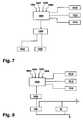
- FIG. 7is a schematic view of an alternative controller mode of the extraction cleaner according to the invention.
- FIG. 8is schematic view of an alternative controller mode of the extraction cleaner according to the invention.
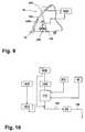
- FIG. 9is a diagrammatic side sectional view of the extraction cleaner of FIGS. 1-5 with a controlled, adjustable agitation brush;
- FIG. 10is a schematic view of a portion of the fluid application system of FIG. 5 according to another embodiment of the invention.
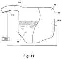
- FIG. 11is a diagrammatic side sectional view of the tank assembly of the extraction cleaner of FIGS 1 - 5 .
- the extraction cleaning machine according to the inventioncan be of the type disclosed in U.S. patent application Ser. No. 09/112,527, filed Jul. 8, 1998, now U.S. Pat. No. 6,167,587, issued Jan. 2, 2001 or U.S. Pat. No. 5,937,475, issued Aug. 17, 1999, both of which are incorporated herein by reference.
- the base module 14includes a lower housing portion 15 and an upper housing portion 17 , which together define an interior for housing components and a well 36 for receiving a tank assembly 50 . Further, a well (not shown) in the upper housing portion 17 receives a detergent supply tank 870 . The upper housing portion 17 receives a transparent facing 19 for defining a first working air conduit 704 and a suction nozzle 34 , which is disposed at a front portion of the base module 14 adjacent the surface being cleaned for recovering fluid therefrom.
- a vacuum source(not shown) is mounted on the base module 14 for drawing air and soiled water through the suction nozzle 34 , through the working air conduit 704 and into a recovery chamber 48 in the tank assembly 50 in which the air is separated from the soiled water in the manner disclosed in the aforementioned U.S. patent application Ser. No. 09/112,527, now U.S. Pat. No. 6,167,587, issued Jan. 2, 2001 or the U.S. Pat. No. 5,937,475. The air is then exhausted from the base module in conventional fashion.
- the handle assembly 16has a closed loop grip 18 provided at the uppermost portion thereof and a combination hose and cord wrap 20 that is adapted to support an accessory hose 22 and a electrical cord (not shown) when either is not in use.
- a conventional latch assembly(not shown) is mounted to the rear portion of the base module 14 adjacent the rotational union of the handle assembly 16 therewith for releasably locking the handle assembly 16 in its upright position.
- the extraction cleaning machine 12is powered in a forward direction by a motor 196 which is controlled by a main power switch 194 disposed on the handle assembly 16 .
- a heater 54(FIG. 5) is mounted in the handle assembly 16 or base module 14 in the cleaning fluid supply line to heat the cleaning fluid and can be separately controlled by a heater power switch when the main power switch is in the “on” position.
- the userthen supplies pressurized cleaning solution to the surface to be cleaned by depressing a trigger in the closed loop grip 18 , whereupon solution flows to and through the fluid dispensing nozzles 100 .
- the cleaning machine 12is typically driven forward and can also be driven rearwardly with a reversing motor, with the forward strokes being defined as wet cycles and the rearward strokes being defined as recovery cycles.
- the cleaning solutionis applied to the surface via the fluid dispensing nozzles 100 and the agitation brush scrubs the subjacent surface.
- the suction nozzle 34removes applied solution, as well as dirt and debris, from the surface being cleaned and carries it to the recovery chamber 48 via the working air conduit 704 .
- the extraction cleaning machine 12can also be operated with the vacuum source activated throughout operation, so that applied solution, dirt, or other fluids on the surface being cleaned are removed by the suction nozzle 34 throughout the cleaning cycle. Further, the extraction cleaning machine 12 can be operated with the vacuum source deactivated for a period, allowing the operator to apply solution to the surface through fluid dispensing nozzles 100 for a pre-treat/soak period, with or without agitation, after which the vacuum source can be activated for removal of the applied solution from the surface.
- a conventional rotatably mounted agitation brush 206is to provided near the front of the base module 14 and driven in the manner disclosed in the aforementioned U.S. patent application Ser. No. 09/112,527, now U.S. Pat. No. 6,167,587, issued Jan. 2, 2001 or the U.S. Pat. No. 5,937,475.
- the agitation brushis adapted for floor-responsive adjustment by a floating brush assembly mounted to a bottom portion of the base module 14 . The floating movement of the agitation brush maintains continuous contact between the agitation brush and the surface being cleaned.
- the fluid application system 950conducts fluid from tank assembly 50 and detergent supply tank 870 to fluid dispensing nozzles 100 , which are mounted in a forward portion of the base module 14 .
- the fluid application system 950preferably also supplies accessory cleaning tool 44 , which also has a fluid-dispensing nozzle (not shown). Clean water flows from fluid supply chamber 49 of tank assembly 50 , through conduit 140 and inlet 332 of the mixing valve assembly 310 , which also includes a detergent inlet 336 that is fluidly connected to a detergent supply tank 870 by a conduit 320 .
- the conduit 138includes a trigger valve 134 having a displaceable valve member actuable by a trigger assembly (not shown) for selectively supplying an in-line heater 54 with pressurized cleaning solution. Heated while passing through the heater 54 , the fluid exits the in-line heater 54 via an outlet port 74 , which is fluidly connected via a conduit 136 to an inlet 652 for a flow indicator 650 . An outlet 654 for the flow indicator is fluidly connected to a T-connector 156 via a conduit 134 . The T-connector 156 supplies fluid dispensing nozzles 100 with heated cleaning solution via conduits 126 , 128 .
- the mixing valve assembly 310is positioned intermediate the tank assembly 50 and the solution pump 202 .
- the mixing valve 310a variable mixing valve to accommodate differing mixtures of detergent and clean water, is controlled by the valve controller 1030 , which receives signals from the controller 1000 in response to dirt level measurements taken by the dirt sensor 1010 .
- the variable mixing valve 310comprises a valve body 330 having clean water inlet 332 that is fluidly connected to the tank assembly 50 and detergent inlet 336 that is fluidly connected to detergent supply tank 870 via the conduit 320 and the L-shaped fitting 314 .
- a mixed solution outlet 340is also formed on the valve body 330 and is adapted to conduct the clean water and detergent mixture, i.e., the cleaning solution, from the mixing valve 310 to a fluidly connected pump priming system 280 adjacent the inlet of the pump 202 .
- the extraction cleaner 10includes a controller 1000 .
- Controller 1000is electrically connected to a speed controller 1020 for a motor 196 .
- Motor 196drives rear wheels 552 , such as through a drive belt 208 .
- Controller 1000is also electrically connected to valve controller 1030 for mixing valve 310 .
- Mixing valve 310receives a detergent from detergent supply tank 870 and clean water from tank assembly 50 , and mixes the detergent with the water in a ratio according to the setting of the valve controller 1030 as directed by controller 1000 .
- Controller 1000is further electrically connected to at least one dirt sensor 1010 , for receiving a signal from the sensor 1010 indicating a soil level in the surface being cleaned.
- the controller 1000is programmed to act on incoming signals and apply control signals, if appropriate, to a variable cleaning control element.
- the controller 1000can be a simple hardwired circuit which applies a control signal to the variable cleaning control element in a linear response to the input dirt sensor signal.
- the controller 1000can be a hardwired circuit or processor which is programmed to output a signal to the variable cleaning control element which is some function of the input signal from the dirt sensor.
- the controller 1000can be a more complex computer controlled device which has a data structure with data representative of the relative degree of dirt in a carpet or on a floor, and output signals which correspond to control settings for one or more variable cleaning control elements in response to a variety of input signals representative of dirt in the carpet, dirt in the extracted water, level of moisture in the carpet, the type and shade of carpet or floor surface.
- the controllercan have a programming function to learn a standard for each carpet or other surface that it cleans. The operational signals can be compared to the standard carpet data learned by the computer and adjustments can then be made accordingly to the variable cleaning control element or elements.
- the controller 1000acts on the incoming signal to output a control signal, if appropriate, to the variable cleaning control element or elements.
- the central processing unitcan compare the signal received from the dirt sensor 1010 with a data structure in a memory having data representative of various degrees of soil in the surface to be cleaned, and generates control signals for adjusting the speed of motor 196 , or the mixture of solution in mixing valve 310 , or both, to match the detected degree of soil in the surface being cleaned.
- the controller 1000applies the control signals to the valve controller 1030 and/or to the speed controller 1020 according to selected operating instructions and responsive to the input signal received from the dirt sensor 1010 .
- the valve controller 1030preferably includes a solenoid (not shown) or other electrically operated valve for mechanically adjusting the mixing valve 310 .
- the speed controller 1020preferably varies the power to the motor in a forward direction, thereby varying the speed of the wheels 552 .
- a standard feedback loopis provided from the speed controller 1020 to the controller 1000 to determine when the speed of the motor reaches the desired speed.
- the controller 1000is programmed to compare the feedback signal from the speed controller 1020 with the control signal and continues to apply the control signal to the speed controller 1020 until the motor reaches the desired speed.
- a feedback loopis provided between the valve controller 1030 and the controller 1000 to when the valve reaches the desired degree of adjustment.
- the controller 1000is programmed to compare the feedback signal from the valve controller 1030 with the control signal and to continue to apply the control signal to the valve controller 1030 until the valve actuator reaches the desired location.
- Dirt sensor 1010is a reflectometer directed at the surface to be cleaned, for measuring the reflectivity of the surface to be cleaned.
- the dirt sensor 1010preferably includes a light source for transmitting radiation onto the surface being cleaned, and a detector for receiving radiation diffusely reflected by the surface.
- the light sourcecan be a tungsten-halogen lamp and the detector can be a series of photoconductive cells, such as lead sulfide cells.
- the detectorgenerates signals indicative of the characteristics of the surface being cleaned. Each cell generates an output signal indicative of the intensity of the reflected radiation within the respective frequency band unique to that cell.
- the data structurewill preferably include reflectance reference data gathered from taking a control reading on a clean carpet segment.
- the processorcompares the reflection characteristics of the surface to the reference data to identify the level of dirt present on the surface being cleaned, regardless of the base color of that surface.
- an alternative dirt sensor 1012is a densitometer, photometer or other device for detecting characteristics of the dirty solution being extracted from the surface to be cleaned as it passes through working air conduit 704 .
- a light sourcetransmits radiation onto the recovered fluid in the working air conduit 704 and a sensor picks up the transmitted light.
- the transmitted light sensed in the working air conduit 704is a measure of the dirt in the recovered solution passing through the working air conduit 704 .
- the controller 1000is programmed to compare the signal generated from the extracted fluid to data recorded in the controller for fluid extractions correlated to given soil levels in the surface being cleaned.
- the controller 1000can also be programmed to respond to a change in the detected soil level as represented by a change in the intensity of the light transmitted to sensor 1012 .
- sensors 1012for detecting characteristics of the dirty solution extracted from the surface being cleaned, are also anticipated.
- sensorscan include an infrared sensor, a conductivity sensor, an image digitizer, spectral analysis of solution color, and a moisture sensor.
- a light emitting diodeis a source of infrared radiation, and the sensor signal is generated by a photocell. The signal is based on the clarity of the extracted solution.
- a conductivity sensorwill generate a signal related to the conductivity of the extracted solution, which varies as the solids increase in the solution.
- This increase in conductivitycan be compared to a zero standard, or to a known dirty extraction fluid standard, or can be compared to the conductivity of the cleaning solution that is being sprayed on the surface to be cleaned.
- the lattermay be a preferred comparison, as differing water sources, due to water hardness and other factors might mandate use of the comparison in order to give a truer indication of the level of solids actually being extracted from the surface, rather than those already existing in the cleaning solution.
- a digitized image of a water samplecould be compared with images prepared for the purpose of establishing a standard for comparison, which can include spectral analysis of the image.
- Another measurement scenario for spectral analysisis to pass extracted solution in front of a standard background, where the color of the background is the same as the cleaning solution before application to the surface.
- the color of the cleaning solutionis reported to the controller 1000 by clean fluid color sensors 1016
- the color of the recovered solutionis read by recovered fluid color sensors 1018 in working conduit 704 .
- the sensorwill give a certain signal. If no solution is being extracted the same signal will be given. If the extracted solution does not match the background of the clean solution, the sensor can then give a comparative reading to the clean solution.
- a suggested light source in this situationis an incandescent reflected light source.
- An example of a spectral analyzer suitable for this purposeis manufactured by X-Rite, Inc. of Grandville, Mich.
- An additional method of measuring of the level of dirt that is being extractedis to measure the foam level in the extracted fluid in the recovery chamber 48 , using sensor 1014 , as illustrated in FIG. 6 .
- there are other detectable properties of the extracted fluideither measured against a standard or compared to the fluid that is being sprayed on the surface to be cleaned. These include the addition to the cleaning solution of chemical indicators that exhibit a color or other detectable property that is related to the amount of dirt in the water. This condition can be detected and used to control a variable cleaning control element to adjust the level of cleaning to the amount of dirt in the carpet or other surface.
- a moisture sensoris useful in the context of the control of an extraction cleaning machine, in providing the controller 1000 an indication of the amount of solution remaining on the surface being cleaned. This information can be used, for example, to determine the speed of the vacuum motor, or the speed of the motor 196 in the reverse direction, for example.
- the controller 1000uses the sensor signal, and through it internal logic, determines an output signal for the speed controller 1020 and/or valve controller 1030 .
- Controller 1000can be switched to function in a mixing valve mode, a drive-motor mode, or both, or can be manually overridden by the operator to direct the mixing valve 310 and or motor 196 to function at a certain cleaning level.
- the upright extractor 12can operate with only the speed controller 1020 responsive to the controller 1000 , or in the alternative, the upright extractor 12 can operate with only the valve controller 1030 responsive to the controller 1000 .
- the rear wheels 552can be powered by the motor 196 or unpowered.
- the mixing valve 310can be varied in response to the dirt level detected by the dirt sensor 1010 without regard to a powered drive for the extractor. Still further, the upright extractor 12 can operate with both a speed controller 1020 and a valve controller 1030 , each individually responsive to the controller 1000 .
- the dirt sensor 1010may detect the level of dirt in the recovered fluid in the working air conduit 704 or on the surface being cleaned.
- the speed of movement of the extraction cleaner and/or ratio of detergent to wateris determined by the detected level of dirt in the surface to be cleaned, whether that detection occurs directly from the surface itself or from extracted fluid from that surface.
- the central processor of the controller 1000stores reflection reference data to which it compares the measured reflection data. Preferably, controls are provided to the user to adjust the extent to which the carpet is cleaned, depending on the cleaning variation desired and relative effectiveness of the various predefined cleaning modes.
- the processorcompares the reflection characteristics of the surface to the reference data to identify the level of dirt present on the surface being cleaned, then determines the corresponding cleaning mode for that soil condition, and applies control signals to the speed controller 1020 and/or valve controller 1030 for appropriate cleaning.
- the controller 1000has predefined cleaning solution concentrations and cleaning speeds. Where both a speed controller 1020 and valve controller 1030 are connected to the controller 1000 , the predefined cleaning solution concentrations and cleaning speeds are further coordinated such that the concentration is keyed to the speed, and vice versa, for any particular soil level.
- the cleaning variationsare numerous and an optimal cleaning mode can be defined for relatively narrow ranges of differing soil levels.
- the speed controller 1020adjusts the forward speed to optimize the cleaning speed for the particular surface condition, from fast for relatively clean areas to slow for high-traffic areas.
- the dirt sensor 1010preferably uses a reflectometer to measure color difference in the surface to be cleaned or turbidity of the fluid being extracted from the surface being cleaned. For example, the user can “teach” the extraction cleaner 12 , via the controller 1000 , what is clean and what is dirty by programming the extractor on clean and dirty surfaces, respectively. Or, the reflectometer or other photosensor can make continuous readings and learn as it cleans after a baseline reading is taken. After learning, the controller 1000 controls the extractor speed depending on the dirt sensor reading.
- the valve controller 1030is preferably functionally related to the extractor speed. When the extractor slows for a high-traffic area, the valve controller adjusts the mixing valve 310 accordingly to increase the amount of cleaning solution in the cleaning mixture applied to the carpet or other surface to be cleaned.
- a further embodiment of the inventionincludes the controller 1000 adjusting the power between the internal components of the extractor.
- Such power balancingdevelops more optimal cleaning characteristics in the extractor by balancing the power between the solution spray rate, the travel rate over the surface, the temperature control of the spray solution, and the extraction rate as developed by the suction source.
- the controller 1000adjusts the power by controlling power distribution module 1050 , as shown schematically in FIG. 7 .
- the distribution of power between internal elements of the cleanercan also be accomplished by using a switched reluctance motor, referring to FIG. 8, which will vary the motor speed in concert with the heater wattage so that while the suction is reduced, the heat is boosted in the sprayed fluid, and suction is slowed down to enhance cleaning by providing additional soak time using the higher temperature cleaning solution.
- Another variation in controlling the application and removal of the cleaning solutionis an automatic pre-treat setting where the suction airflow is cut off in extra dirty areas or high traffic areas during a pre-treatment pass of the spraying solution, again to allow additional time for the pre-treatment to work on the dirt in the carpet.
- the controller 1000is programmed to increase the power to the vacuum source, i.e. a burst of power, in high traffic areas, or especially dirty areas, to increase the suction force for a short period to increase the suction applied to the given dirty area.
- This response by the controller 1000is in response to an operator or sensor signal, shown in FIG. 5 as another controller input 1002 , wherein the operator or a sensor indicates to the controller an area on the surface being cleaned that requires concentrated cleaning.
- Controller inputs 1002also signify input of other operator or sensor signals for use by controller 1000 .
- the pressure or speed of the agitation brushcan be varied.
- the agitation brush of an extraction cleanercan be driven at varying speeds determined by the motor powering the agitation brush.
- the brushcan be pressed against the surface being cleaned by releasing the brush under the force of gravity, or by the inclusion of an actuator, such as a solenoid 1060 as shown in FIG. 9, to positively press the brush down against the surface being cleaned.
- the extraction cleanercan further include additional supply tanks 1070 for holding additives to the cleaning solution, such as an oxidizer or booster.
- the additiveis released into the cleaning solution at the intake to pump 202 by a release valve 1072 , which can be actuated either by the controller 1000 or manually by the operator.
- Another method of providing additional cleaning power to the surface to be cleanedis a burst of steam, which can be sensor controlled or manually activated by the operator.
- the water supplied to the heateris reduced or the power to the heater can be increased, which transfers more energy to the water available to the heater, thereby producing a burst of steam.
- This steam added to the cleaning processcan be in a burst of steam or can be a steam “pass” as part of a recommended series of passes during use of the extractor.
- the extractorcan be configured to include a separate steam function whereby all of the available power of the extractor is diverted to the solution-heating element to provide maximum steam flow.
- the upright extractor 12can operate without a dirt sensor, but the speed controller 1020 and valve controller 1030 are responsive to signals from the controller 1040 which is set by the user according to user preference for the level of cleaning. That is, if the user desires a heavy cleaning, moving an actuator knob 1042 on the controller 1040 to a position for heavy cleaning signals the valve controller 1030 to permit a high ratio of detergent to water and signals the speed controller 1020 to slow movement of the extractor to permit thorough agitation and suction of the applied cleaning solution. Similarly, moving the actuator knob 1042 to a lighter cleaning level reduces the concentration of cleaning solution applied at a relatively faster speed.
- the base module 14houses drive motor 196 that is connected to a source of electricity by the electrical cord.
- a motor compartment (not shown) within the base module 14securely mounts motor 196 in place. While the motor 196 as shown drives only rear wheels 552 , the motor 196 can also drive the agitation brush (not shown) as well as an impeller fan (not shown) for creating a vacuum source for drawing dirt, debris and fluid from the surface being cleaned.
- the motor 196includes a motor drive shaft 198 , which includes drive belt 208 thereon for driving the rear wheels 552 .
- the motor drive shaft 198supports the impeller within an impeller housing.
- a single drive motor 196is adapted to provide driving force for the impeller and the rear wheels 552 .
- the motor 196can be used to drive only the rear wheels 552 .
- the motor 196can drive the rear wheels 552 , the impeller, and fluid pump 202 for providing cleaning solution to spray nozzles 100 .
- a clutch(not shown) is provided between the motor 196 and the rear wheels 552 and controlled by a spring biased lever to drive the wheels in a forward direction and to release the drive in a rear direction.
- a clutchcan be provided for driving the rear wheels 552 , the pump, the agitator and the impeller, if desired.
- the drive belt 208is reeved through a pulley 216 mounted on a wheel axle 554 for the rear wheels 552 and a pulley 222 on the drive shaft 198 of the motor 196 .
- the pulleys 216 , 222have toothed perimeters adapted for registration with the teeth in the drive belt 208 .
- the used cleaning solution and entrapped dirtare removed from the surface being cleaned through the suction nozzle 34 , which opens into working air conduit 704 .
- the working air conduit 704terminates in the tank assembly 50 , and more particularly in the recovery chamber 48 therein that fluidly isolates the dirty solution from the clean water.
- the extractoris driven at the optimal rate for cleaning the carpet to reach a predetermined standard.
- the spray and suction ratesare adjusted to optimize the cleaning action of the extractor based on the sensed soil levels in the surface to be cleaned.
- the feedback provided to the usercan take the form of an audible signal, having a differentiation between traveling too fast versus traveling too slow, or a visual signal, such as a speedometer giving the speed of the extractor across the carpet or other surface being cleanes.
- a visual signalsuch as a speedometer giving the speed of the extractor across the carpet or other surface being cleanes.
- An anticipated visual signalwould be, for example, a light bar that would give an indication to the user on a scale showing the actual speed of the extractor compared to the optimal speed on the scale for a particular level of soil in the carpet or other surface being cleanes.
- This comparison between the actual speed of the extractor, as powered manually by the user, and the optimal speed of the extractorcan be based on a pre-programmed speed as determined by experimentation or can be determined by an electronic controller upon evaluation of the effectiveness of cleaning of the extractor in response to the sensor signals provided to the controller and previously discussed.
- the pre-programmed optimal speedcan be available in different levels or modes, such as for normal cleaning or high traffic areas.
- the signal from the controller 1000can be a signal representative of the amount of dirt in the carpet. The operator can manually override the controller to adjust the amount of cleaning by the extractor by manually adjusting any of the manual controls of the extractor or by providing specific inputs to the controller 1000 through inputs 1002 shown in FIG. 5 .
- a manual override input 1028can be provided on the speed controller 1020 to manually set a level of speed for the extractor based on the amount of dirt sensed by the sensor 1010 .
- the same type of override controlcan be provided on any of the variable control elements on the extractor.
- the controller 1000is connected to a visual display device 1024 and is adapted to apply to the visual display device 1024 a signal which is converted in the visual display device 1024 to a digital or analog reading on a screen or meter in the visual display device 1024 to indicate the level of dirt in the carpet.
- the visual display device 1024can include an speaker 1026 , which delivers an audible signal responsive to a signal from the controller 1000 .
Landscapes
- Cleaning By Liquid Or Steam (AREA)
Abstract
Description
Claims (41)
Priority Applications (3)
| Application Number | Priority Date | Filing Date | Title |
|---|---|---|---|
| US09/593,126US6446302B1 (en) | 1999-06-14 | 2000-06-13 | Extraction cleaning machine with cleaning control |
| US10/044,890US6800140B2 (en) | 2000-06-13 | 2002-01-11 | Extraction cleaning with optimal cleaning speed |
| US10/064,723US7062816B2 (en) | 1999-06-14 | 2002-08-09 | Surface cleaner with power drive |
Applications Claiming Priority (2)
| Application Number | Priority Date | Filing Date | Title |
|---|---|---|---|
| US13912799P | 1999-06-14 | 1999-06-14 | |
| US09/593,126US6446302B1 (en) | 1999-06-14 | 2000-06-13 | Extraction cleaning machine with cleaning control |
Related Child Applications (2)
| Application Number | Title | Priority Date | Filing Date |
|---|---|---|---|
| US10/044,890Continuation-In-PartUS6800140B2 (en) | 2000-06-13 | 2002-01-11 | Extraction cleaning with optimal cleaning speed |
| US10/064,723Continuation-In-PartUS7062816B2 (en) | 1999-06-14 | 2002-08-09 | Surface cleaner with power drive |
Publications (1)
| Publication Number | Publication Date |
|---|---|
| US6446302B1true US6446302B1 (en) | 2002-09-10 |
Family
ID=26836890
Family Applications (1)
| Application Number | Title | Priority Date | Filing Date |
|---|---|---|---|
| US09/593,126Expired - LifetimeUS6446302B1 (en) | 1999-06-14 | 2000-06-13 | Extraction cleaning machine with cleaning control |
Country Status (1)
| Country | Link |
|---|---|
| US (1) | US6446302B1 (en) |
Cited By (104)
| Publication number | Priority date | Publication date | Assignee | Title |
|---|---|---|---|---|
| US20010039684A1 (en)* | 1997-07-09 | 2001-11-15 | Kasper Gary A. | Extraction cleaning with heating |
| US20020170137A1 (en)* | 2001-05-21 | 2002-11-21 | Coates Donald A. | Apparatus and method for cleaning a surface |
| US20030014829A1 (en)* | 2001-07-17 | 2003-01-23 | Donglei Wang | Water absorbing and drying cleaner |
| US20030041880A1 (en)* | 2000-03-17 | 2003-03-06 | Udall Alan Leslie | Cleaning of surfaces |
| US20040154124A1 (en)* | 2001-10-17 | 2004-08-12 | Dexter Lehman | Dual cleaning mode carpet extractor |
| US6812847B1 (en) | 2000-08-25 | 2004-11-02 | The Hoover Company | Moisture indicator for wet pick-up suction cleaner |
| US20040221415A1 (en)* | 2003-05-08 | 2004-11-11 | Tondra Aaron P. | Cleaning machine having a control system for cleaning a surface |
| US6832407B2 (en)* | 2000-08-25 | 2004-12-21 | The Hoover Company | Moisture indicator for wet pick-up suction cleaner |
| US20050045738A1 (en)* | 2003-08-27 | 2005-03-03 | David Baxter | System for maintaining gutter debris free |
| US6864985B1 (en)* | 1999-05-19 | 2005-03-08 | Merck Patent Gmbh | Measuring turbidities by reflectometry |
| US20050120504A1 (en)* | 2003-12-04 | 2005-06-09 | Tondra Aaron P. | Floor care appliance with network connectivity |
| US20050120507A1 (en)* | 2003-12-06 | 2005-06-09 | Kegg Steven W. | Cleaning machine for cleaning a surface |
| US20050160556A1 (en)* | 2004-01-23 | 2005-07-28 | Hitzelberger J. E. | Floor care apparatus with multiple agitator speeds and constant suction power |
| US20050218713A1 (en)* | 2004-04-05 | 2005-10-06 | Oreck Holdings, Llc | Height adjustment apparatus for a rotatable component of a vacuum cleaner |
| US6956348B2 (en) | 2004-01-28 | 2005-10-18 | Irobot Corporation | Debris sensor for cleaning apparatus |
| US20050236021A1 (en)* | 2004-04-15 | 2005-10-27 | Funai Electric Co., Ltd. | Self-propelled cleaner |
| US20050279059A1 (en)* | 2004-06-22 | 2005-12-22 | Samsung Electronics Co., Ltd. | Air purifier and control method thereof |
| US7013749B2 (en) | 2004-06-07 | 2006-03-21 | Tesco Engineering, Inc. | Robot driven robot index system |
| US20060086272A1 (en)* | 2004-10-22 | 2006-04-27 | Pdm Limited | Web cleaner |
| US20060090285A1 (en)* | 2004-11-03 | 2006-05-04 | Lg Electronics Inc. | Complex type cleaner |
| EP1677099A1 (en)* | 2004-12-30 | 2006-07-05 | Danmarks Tekniske Universitet | Method and apparatus for classification of surfaces |
| US20060179599A1 (en)* | 2003-03-31 | 2006-08-17 | Miner Jonathan L | Unattended spot cleaning apparatus |
| US20060207052A1 (en)* | 2005-03-18 | 2006-09-21 | Bissell Homecare, Inc. | Unattended spot cleaning apparatus |
| US7155308B2 (en) | 2000-01-24 | 2006-12-26 | Irobot Corporation | Robot obstacle detection system |
| US7320149B1 (en)* | 2002-11-22 | 2008-01-22 | Bissell Homecare, Inc. | Robotic extraction cleaner with dusting pad |
| US7332890B2 (en) | 2004-01-21 | 2008-02-19 | Irobot Corporation | Autonomous robot auto-docking and energy management systems and methods |
| US7389156B2 (en) | 2005-02-18 | 2008-06-17 | Irobot Corporation | Autonomous surface cleaning robot for wet and dry cleaning |
| US20080189900A1 (en)* | 2005-03-16 | 2008-08-14 | Pierantonio Milanese | Steam Broom for Floor Cleaning with Adjustable Steam Jets Underneath and/or at the Front and with Detergent Mixing |
| US20090165238A1 (en)* | 2003-10-08 | 2009-07-02 | Leslie Bennett | Web substrate cleaning systems & methods |
| US7620476B2 (en) | 2005-02-18 | 2009-11-17 | Irobot Corporation | Autonomous surface cleaning robot for dry cleaning |
| US7706917B1 (en) | 2004-07-07 | 2010-04-27 | Irobot Corporation | Celestial navigation system for an autonomous robot |
| US7761954B2 (en) | 2005-02-18 | 2010-07-27 | Irobot Corporation | Autonomous surface cleaning robot for wet and dry cleaning |
| US20110000037A1 (en)* | 2009-07-01 | 2011-01-06 | Racine Industries, Inc. | Combination of Carpet-Cleaning Machine and Platform for Transporting the Machine |
| US20120011677A1 (en)* | 2010-07-15 | 2012-01-19 | Samsung Electronics Co., Ltd. | Robot cleaner, maintenance station, and cleaning system having the same |
| US8239992B2 (en) | 2007-05-09 | 2012-08-14 | Irobot Corporation | Compact autonomous coverage robot |
| US8368339B2 (en) | 2001-01-24 | 2013-02-05 | Irobot Corporation | Robot confinement |
| US8374721B2 (en) | 2005-12-02 | 2013-02-12 | Irobot Corporation | Robot system |
| US8380350B2 (en) | 2005-12-02 | 2013-02-19 | Irobot Corporation | Autonomous coverage robot navigation system |
| US8382906B2 (en) | 2005-02-18 | 2013-02-26 | Irobot Corporation | Autonomous surface cleaning robot for wet cleaning |
| US8386081B2 (en) | 2002-09-13 | 2013-02-26 | Irobot Corporation | Navigational control system for a robotic device |
| US8396592B2 (en) | 2001-06-12 | 2013-03-12 | Irobot Corporation | Method and system for multi-mode coverage for an autonomous robot |
| US8412377B2 (en) | 2000-01-24 | 2013-04-02 | Irobot Corporation | Obstacle following sensor scheme for a mobile robot |
| US8417383B2 (en) | 2006-05-31 | 2013-04-09 | Irobot Corporation | Detecting robot stasis |
| US8418303B2 (en) | 2006-05-19 | 2013-04-16 | Irobot Corporation | Cleaning robot roller processing |
| US8428778B2 (en) | 2002-09-13 | 2013-04-23 | Irobot Corporation | Navigational control system for a robotic device |
| US8463438B2 (en) | 2001-06-12 | 2013-06-11 | Irobot Corporation | Method and system for multi-mode coverage for an autonomous robot |
| US8474090B2 (en) | 2002-01-03 | 2013-07-02 | Irobot Corporation | Autonomous floor-cleaning robot |
| US8515578B2 (en) | 2002-09-13 | 2013-08-20 | Irobot Corporation | Navigational control system for a robotic device |
| USD689252S1 (en)* | 2012-03-09 | 2013-09-03 | Bissell Homecare, Inc. | Portion of floor cleaning machine |
| US8584307B2 (en) | 2005-12-02 | 2013-11-19 | Irobot Corporation | Modular robot |
| US8600553B2 (en) | 2005-12-02 | 2013-12-03 | Irobot Corporation | Coverage robot mobility |
| US8719998B1 (en)* | 2010-05-12 | 2014-05-13 | Bissell Homecare, Inc. | Extractor with light-sensitive stain sensor |
| US8780342B2 (en) | 2004-03-29 | 2014-07-15 | Irobot Corporation | Methods and apparatus for position estimation using reflected light sources |
| US8788092B2 (en) | 2000-01-24 | 2014-07-22 | Irobot Corporation | Obstacle following sensor scheme for a mobile robot |
| US8800107B2 (en) | 2010-02-16 | 2014-08-12 | Irobot Corporation | Vacuum brush |
| USD718010S1 (en)* | 2013-01-23 | 2014-11-18 | Bissell Homecare, Inc. | Extraction cleaner base |
| US8930023B2 (en) | 2009-11-06 | 2015-01-06 | Irobot Corporation | Localization by learning of wave-signal distributions |
| US8972052B2 (en) | 2004-07-07 | 2015-03-03 | Irobot Corporation | Celestial navigation system for an autonomous vehicle |
| US9008835B2 (en) | 2004-06-24 | 2015-04-14 | Irobot Corporation | Remote control scheduler and method for autonomous robotic device |
| US20150216385A1 (en)* | 2014-02-04 | 2015-08-06 | Techtronic Floor Care Technology Limited | Extractor cleaning machine |
| US20150245751A1 (en)* | 2014-02-28 | 2015-09-03 | Rug Doctor, LLC | Liquid Extraction Cleaning Device |
| EP2944942A1 (en)* | 2014-05-16 | 2015-11-18 | Vorwerk & Co. Interholding GmbH | Automotive cleaner |
| US9320398B2 (en) | 2005-12-02 | 2016-04-26 | Irobot Corporation | Autonomous coverage robots |
| US20160157693A1 (en)* | 2013-07-02 | 2016-06-09 | Alfred Kärcher Gmbh & Co. Kg | Steam device and method for operating a steam device |
| US9532689B2 (en) | 2014-04-15 | 2017-01-03 | Shop Vac Corporation | Airflow indicator assembly and method for vacuum cleaner |
| US9775485B2 (en) | 2013-06-03 | 2017-10-03 | Bissell Homecare, Inc. | Autonomous floor cleaner |
| US20170311770A1 (en)* | 2016-04-29 | 2017-11-02 | Wal-Mart Stores, Inc. | Index of Refraction Floor Scrubber to Determine Traffic |
| EP3287863A1 (en) | 2004-01-28 | 2018-02-28 | iRobot Corporation | Autonomous cleaning apparatus with debris sensor |
| EP3440982A1 (en)* | 2017-08-10 | 2019-02-13 | Vorwerk & Co. Interholding GmbH | Soil working tool with multiple tanks for storing of liquid |
| US10458938B2 (en) | 2013-03-14 | 2019-10-29 | Ecolab Usa Inc. | System and method for monitoring of floor conditions |
| US10489935B2 (en) | 2016-08-16 | 2019-11-26 | Walmart Apollo, Llc | Systems and methods for determining crowd traffic by detecting debris in floor mats |
| US10548450B2 (en) | 2013-07-02 | 2020-02-04 | Alfred Kärcher SE & Co. KG | Suction device and method for operating a suction device |
| CN110811440A (en)* | 2019-12-06 | 2020-02-21 | 珠海格力电器股份有限公司 | Cleaning devices and cleaning equipment |
| US10602898B2 (en) | 2017-06-05 | 2020-03-31 | Bissell Homecare, Inc. | Autonomous floor cleaning system |
| CN111443033A (en)* | 2020-04-26 | 2020-07-24 | 武汉理工大学 | A kind of sweeping robot carpet detection method |
| US10813520B2 (en) | 2017-12-18 | 2020-10-27 | Techtronic Floor Care Technology Limited | Surface cleaning device with triggerless fluid distribution mechanism |
| CN112545398A (en)* | 2020-12-07 | 2021-03-26 | 添可智能科技有限公司 | Cleaning device and method for automatically controlling cleaning liquid adding of cleaning device |
| CN112754349A (en)* | 2019-11-06 | 2021-05-07 | 必胜公司 | Surface cleaning apparatus and method of controlling flow rate of surface cleaning apparatus |
| US20210251452A1 (en)* | 2018-08-07 | 2021-08-19 | Koninklijke Philips N.V. | Wet cleaning device |
| CN113509113A (en)* | 2020-04-09 | 2021-10-19 | 添可智能科技有限公司 | Surface working apparatus, liquid transport method, and storage medium |
| US11202543B2 (en) | 2018-01-17 | 2021-12-21 | Techtronic Floor Care Technology Limited | System and method for operating a cleaning system based on a surface to be cleaned |
| CN113842088A (en)* | 2021-09-13 | 2021-12-28 | 深圳甲壳虫智能有限公司 | Intelligent cleaning equipment |
| CN114532701A (en)* | 2018-06-22 | 2022-05-27 | 必胜公司 | Surface cleaning device |
| US11382477B2 (en) | 2017-12-18 | 2022-07-12 | Techtronic Floor Care Technology Limited | Surface cleaning device with automated control |
| CN114798523A (en)* | 2019-10-09 | 2022-07-29 | 添可智能科技有限公司 | Cleaning machine |
| EP4026472A4 (en)* | 2019-09-04 | 2022-11-09 | Tineco Intelligent Technology Co., Ltd. | CLEANING MACHINE, CLEANING DEVICE, CONTROL METHOD THEREOF, INFORMATION DISPLAY METHOD AND STORAGE MEDIA |
| CN115316892A (en)* | 2022-08-02 | 2022-11-11 | 安克创新科技股份有限公司 | Cleaning device and control method of cleaning device |
| CN115381347A (en)* | 2022-08-25 | 2022-11-25 | 安克创新科技股份有限公司 | Cleaning apparatus and control method of cleaning apparatus |
| WO2022267894A1 (en)* | 2021-02-10 | 2022-12-29 | 北京顺造科技有限公司 | Cleaning liquid interaction method for surface cleaning system, and surface cleaning system |
| US11576541B2 (en) | 2021-03-04 | 2023-02-14 | Bissell Inc. | Surface cleaning apparatus |
| CN116134495A (en)* | 2020-07-16 | 2023-05-16 | 锡克拜控股有限公司 | Methods and systems for detecting and authenticating tracers in labels via surface-enhanced Raman spectroscopy |
| CN116327056A (en)* | 2023-04-20 | 2023-06-27 | 云鲸智能(深圳)有限公司 | Control method of cleaning device, cleaning device and computer readable storage medium |
| CN116327038A (en)* | 2023-05-06 | 2023-06-27 | 广东浩宇清洁环保设备有限公司 | Sofa cleaning device of intelligent regulation and control dirt suction mode |
| US11701681B2 (en) | 2014-06-13 | 2023-07-18 | The Procter & Gamble Company | Device and methods for depositing materials on hard surfaces |
| US11730332B2 (en) | 2021-03-04 | 2023-08-22 | Bissell Inc. | Surface cleaning apparatus |
| US11737629B2 (en) | 2019-01-08 | 2023-08-29 | Bissell Inc. | Surface cleaning apparatus |
| US11910977B2 (en) | 2022-01-10 | 2024-02-27 | Bissell Inc. | Surface cleaning apparatus with steam |
| USD1017156S1 (en) | 2022-05-09 | 2024-03-05 | Dupray Ventures Inc. | Cleaner |
| JP2024518870A (en)* | 2021-03-17 | 2024-05-08 | ヴェルスニ ホールディング ビー ヴィ | Supplying liquid to at least one area of the surface to be cleaned |
| US11986139B2 (en) | 2022-02-02 | 2024-05-21 | Bissell Inc. | Extraction cleaner with steam |
| US12042107B2 (en) | 2021-03-04 | 2024-07-23 | Bissell Inc. | Surface cleaning apparatus |
| US12096905B2 (en) | 2021-03-17 | 2024-09-24 | Dupray Ventures Inc. | Spot cleaner apparatus |
| US20240415355A1 (en)* | 2022-01-11 | 2024-12-19 | Versuni Holding B.V. | Wet cleaning apparatus and cleaner head |
| US12239267B2 (en) | 2019-07-02 | 2025-03-04 | Mark Jeffery Giarritta | Four-direction scrubbing carpet shampooer |
Citations (14)
| Publication number | Priority date | Publication date | Assignee | Title |
|---|---|---|---|---|
| US3952361A (en)* | 1973-10-05 | 1976-04-27 | R. G. Dixon & Company Limited | Floor treating machines |
| US5237720A (en) | 1990-05-04 | 1993-08-24 | Bissell Inc. | Carpet extractor with bucket caddy |
| US5323483A (en)* | 1991-06-25 | 1994-06-21 | Goldstar Co., Ltd. | Apparatus and method for controlling speed of suction motor in vacuum cleaner |
| US5539953A (en) | 1992-01-22 | 1996-07-30 | Kurz; Gerhard | Floor nozzle for vacuum cleaners |
| US5608944A (en)* | 1995-06-05 | 1997-03-11 | The Hoover Company | Vacuum cleaner with dirt detection |
| US5613261A (en)* | 1994-04-14 | 1997-03-25 | Minolta Co., Ltd. | Cleaner |
| US5815884A (en)* | 1996-11-27 | 1998-10-06 | Yashima Electric Co., Ltd. | Dust indication system for vacuum cleaner |
| US5841259A (en) | 1993-08-07 | 1998-11-24 | Samsung Electronics Co., Ltd. | Vacuum cleaner and control method thereof |
| US5839156A (en) | 1995-12-19 | 1998-11-24 | Kwangju Electronics Co., Ltd. | Remote controllable automatic moving vacuum cleaner |
| US5867861A (en) | 1995-11-13 | 1999-02-09 | Kasen; Timothy E. | Upright water extraction cleaning machine with two suction nozzles |
| US5937475A (en) | 1995-11-06 | 1999-08-17 | Bissell Inc. | Water extraction cleaning machine with variable solution mixing valve |
| US5987696A (en)* | 1996-12-24 | 1999-11-23 | Wang; Kevin W. | Carpet cleaning machine |
| US6167587B1 (en)* | 1997-07-09 | 2001-01-02 | Bissell Homecare, Inc. | Upright extraction cleaning machine |
| US6176940B1 (en)* | 1996-12-24 | 2001-01-23 | Kevin Wang | Method of vacuum adjustment in a cleaning machine |
- 2000
- 2000-06-13USUS09/593,126patent/US6446302B1/ennot_activeExpired - Lifetime
Patent Citations (15)
| Publication number | Priority date | Publication date | Assignee | Title |
|---|---|---|---|---|
| US3952361A (en)* | 1973-10-05 | 1976-04-27 | R. G. Dixon & Company Limited | Floor treating machines |
| US5237720A (en) | 1990-05-04 | 1993-08-24 | Bissell Inc. | Carpet extractor with bucket caddy |
| US5323483A (en)* | 1991-06-25 | 1994-06-21 | Goldstar Co., Ltd. | Apparatus and method for controlling speed of suction motor in vacuum cleaner |
| US5539953A (en) | 1992-01-22 | 1996-07-30 | Kurz; Gerhard | Floor nozzle for vacuum cleaners |
| US5841259A (en) | 1993-08-07 | 1998-11-24 | Samsung Electronics Co., Ltd. | Vacuum cleaner and control method thereof |
| US5613261A (en)* | 1994-04-14 | 1997-03-25 | Minolta Co., Ltd. | Cleaner |
| US5608944A (en)* | 1995-06-05 | 1997-03-11 | The Hoover Company | Vacuum cleaner with dirt detection |
| US5937475A (en) | 1995-11-06 | 1999-08-17 | Bissell Inc. | Water extraction cleaning machine with variable solution mixing valve |
| US5867861A (en) | 1995-11-13 | 1999-02-09 | Kasen; Timothy E. | Upright water extraction cleaning machine with two suction nozzles |
| US5839156A (en) | 1995-12-19 | 1998-11-24 | Kwangju Electronics Co., Ltd. | Remote controllable automatic moving vacuum cleaner |
| US5815884A (en)* | 1996-11-27 | 1998-10-06 | Yashima Electric Co., Ltd. | Dust indication system for vacuum cleaner |
| US6055702A (en) | 1996-11-27 | 2000-05-02 | Yashima Electric Co., Ltd. | Vacuum cleaner |
| US5987696A (en)* | 1996-12-24 | 1999-11-23 | Wang; Kevin W. | Carpet cleaning machine |
| US6176940B1 (en)* | 1996-12-24 | 2001-01-23 | Kevin Wang | Method of vacuum adjustment in a cleaning machine |
| US6167587B1 (en)* | 1997-07-09 | 2001-01-02 | Bissell Homecare, Inc. | Upright extraction cleaning machine |
Cited By (238)
| Publication number | Priority date | Publication date | Assignee | Title |
|---|---|---|---|---|
| US20010039684A1 (en)* | 1997-07-09 | 2001-11-15 | Kasper Gary A. | Extraction cleaning with heating |
| US6898820B2 (en)* | 1997-07-09 | 2005-05-31 | Bissell Homecare, Inc. | Extraction cleaning with heating |
| US6864985B1 (en)* | 1999-05-19 | 2005-03-08 | Merck Patent Gmbh | Measuring turbidities by reflectometry |
| US9446521B2 (en) | 2000-01-24 | 2016-09-20 | Irobot Corporation | Obstacle following sensor scheme for a mobile robot |
| US7155308B2 (en) | 2000-01-24 | 2006-12-26 | Irobot Corporation | Robot obstacle detection system |
| US8478442B2 (en) | 2000-01-24 | 2013-07-02 | Irobot Corporation | Obstacle following sensor scheme for a mobile robot |
| US8412377B2 (en) | 2000-01-24 | 2013-04-02 | Irobot Corporation | Obstacle following sensor scheme for a mobile robot |
| US8565920B2 (en) | 2000-01-24 | 2013-10-22 | Irobot Corporation | Obstacle following sensor scheme for a mobile robot |
| US8788092B2 (en) | 2000-01-24 | 2014-07-22 | Irobot Corporation | Obstacle following sensor scheme for a mobile robot |
| US8761935B2 (en) | 2000-01-24 | 2014-06-24 | Irobot Corporation | Obstacle following sensor scheme for a mobile robot |
| US6804856B2 (en)* | 2000-03-17 | 2004-10-19 | Duplex Cleaning Machines (Uk) Limited | Cleaning of surfaces |
| US20030041880A1 (en)* | 2000-03-17 | 2003-03-06 | Udall Alan Leslie | Cleaning of surfaces |
| US9144361B2 (en) | 2000-04-04 | 2015-09-29 | Irobot Corporation | Debris sensor for cleaning apparatus |
| US6832407B2 (en)* | 2000-08-25 | 2004-12-21 | The Hoover Company | Moisture indicator for wet pick-up suction cleaner |
| US6812847B1 (en) | 2000-08-25 | 2004-11-02 | The Hoover Company | Moisture indicator for wet pick-up suction cleaner |
| US8368339B2 (en) | 2001-01-24 | 2013-02-05 | Irobot Corporation | Robot confinement |
| US20150374188A1 (en)* | 2001-01-24 | 2015-12-31 | Irobot Corporation | Debris sensor for cleaning apparatus |
| US9167946B2 (en) | 2001-01-24 | 2015-10-27 | Irobot Corporation | Autonomous floor cleaning robot |
| US9582005B2 (en) | 2001-01-24 | 2017-02-28 | Irobot Corporation | Robot confinement |
| US9591959B2 (en)* | 2001-01-24 | 2017-03-14 | Irobot Corporation | Debris sensor for cleaning apparatus |
| US9038233B2 (en) | 2001-01-24 | 2015-05-26 | Irobot Corporation | Autonomous floor-cleaning robot |
| US8686679B2 (en) | 2001-01-24 | 2014-04-01 | Irobot Corporation | Robot confinement |
| US9883783B2 (en)* | 2001-01-24 | 2018-02-06 | Irobot Corporation | Debris sensor for cleaning apparatus |
| US9622635B2 (en) | 2001-01-24 | 2017-04-18 | Irobot Corporation | Autonomous floor-cleaning robot |
| US7146679B2 (en)* | 2001-05-21 | 2006-12-12 | The Hoover Company | Apparatus and method for cleaning a surface |
| US6681442B2 (en)* | 2001-05-21 | 2004-01-27 | The Hoover Company | Apparatus and method for cleaning a surface |
| US20020170137A1 (en)* | 2001-05-21 | 2002-11-21 | Coates Donald A. | Apparatus and method for cleaning a surface |
| US8396592B2 (en) | 2001-06-12 | 2013-03-12 | Irobot Corporation | Method and system for multi-mode coverage for an autonomous robot |
| US8463438B2 (en) | 2001-06-12 | 2013-06-11 | Irobot Corporation | Method and system for multi-mode coverage for an autonomous robot |
| US9104204B2 (en) | 2001-06-12 | 2015-08-11 | Irobot Corporation | Method and system for multi-mode coverage for an autonomous robot |
| US7000286B2 (en)* | 2001-07-17 | 2006-02-21 | Donglei Wang | Water absorbing and drying cleaner |
| US20030014829A1 (en)* | 2001-07-17 | 2003-01-23 | Donglei Wang | Water absorbing and drying cleaner |
| US20040154124A1 (en)* | 2001-10-17 | 2004-08-12 | Dexter Lehman | Dual cleaning mode carpet extractor |
| US20080201896A1 (en)* | 2001-10-17 | 2008-08-28 | Nilfisk-Advance, Inc. | Dual Cleaning Mode Carpet Extractor |
| US7370386B2 (en)* | 2001-10-17 | 2008-05-13 | Nilfisk-Advance, Inc. | Dual cleaning mode carpet extractor |
| US8516651B2 (en) | 2002-01-03 | 2013-08-27 | Irobot Corporation | Autonomous floor-cleaning robot |
| US8474090B2 (en) | 2002-01-03 | 2013-07-02 | Irobot Corporation | Autonomous floor-cleaning robot |
| US9128486B2 (en) | 2002-01-24 | 2015-09-08 | Irobot Corporation | Navigational control system for a robotic device |
| US8428778B2 (en) | 2002-09-13 | 2013-04-23 | Irobot Corporation | Navigational control system for a robotic device |
| US8515578B2 (en) | 2002-09-13 | 2013-08-20 | Irobot Corporation | Navigational control system for a robotic device |
| US8781626B2 (en) | 2002-09-13 | 2014-07-15 | Irobot Corporation | Navigational control system for a robotic device |
| US8793020B2 (en) | 2002-09-13 | 2014-07-29 | Irobot Corporation | Navigational control system for a robotic device |
| US8386081B2 (en) | 2002-09-13 | 2013-02-26 | Irobot Corporation | Navigational control system for a robotic device |
| US9949608B2 (en) | 2002-09-13 | 2018-04-24 | Irobot Corporation | Navigational control system for a robotic device |
| US7320149B1 (en)* | 2002-11-22 | 2008-01-22 | Bissell Homecare, Inc. | Robotic extraction cleaner with dusting pad |
| US7228589B2 (en) | 2003-03-31 | 2007-06-12 | Bissell Homecare, Inc. | Unattended spot cleaning apparatus |
| CN1767782B (en)* | 2003-03-31 | 2011-01-19 | 碧洁家庭护理有限公司 | Unattended spot cleaning unit |
| US20060179599A1 (en)* | 2003-03-31 | 2006-08-17 | Miner Jonathan L | Unattended spot cleaning apparatus |
| US7237299B2 (en) | 2003-05-08 | 2007-07-03 | The Hoover Company | Cleaning machine having a control system for cleaning a surface |
| US20040221415A1 (en)* | 2003-05-08 | 2004-11-11 | Tondra Aaron P. | Cleaning machine having a control system for cleaning a surface |
| US6926210B2 (en)* | 2003-08-27 | 2005-08-09 | David Baxter | System for maintaining gutter debris free |
| US20050045738A1 (en)* | 2003-08-27 | 2005-03-03 | David Baxter | System for maintaining gutter debris free |
| US20090165238A1 (en)* | 2003-10-08 | 2009-07-02 | Leslie Bennett | Web substrate cleaning systems & methods |
| US20050120504A1 (en)* | 2003-12-04 | 2005-06-09 | Tondra Aaron P. | Floor care appliance with network connectivity |
| US7269877B2 (en) | 2003-12-04 | 2007-09-18 | The Hoover Company | Floor care appliance with network connectivity |
| US20050120507A1 (en)* | 2003-12-06 | 2005-06-09 | Kegg Steven W. | Cleaning machine for cleaning a surface |
| US7240394B2 (en) | 2003-12-06 | 2007-07-10 | The Hoover Company | Cleaning machine for cleaning a surface |
| US8390251B2 (en) | 2004-01-21 | 2013-03-05 | Irobot Corporation | Autonomous robot auto-docking and energy management systems and methods |
| US9215957B2 (en) | 2004-01-21 | 2015-12-22 | Irobot Corporation | Autonomous robot auto-docking and energy management systems and methods |
| US8854001B2 (en) | 2004-01-21 | 2014-10-07 | Irobot Corporation | Autonomous robot auto-docking and energy management systems and methods |
| US8461803B2 (en) | 2004-01-21 | 2013-06-11 | Irobot Corporation | Autonomous robot auto-docking and energy management systems and methods |
| US8749196B2 (en) | 2004-01-21 | 2014-06-10 | Irobot Corporation | Autonomous robot auto-docking and energy management systems and methods |
| US7332890B2 (en) | 2004-01-21 | 2008-02-19 | Irobot Corporation | Autonomous robot auto-docking and energy management systems and methods |
| US7251858B2 (en) | 2004-01-23 | 2007-08-07 | Panasonic Corporation Of North America | Floor care apparatus with multiple agitator speeds and constant suction power |
| US20050160556A1 (en)* | 2004-01-23 | 2005-07-28 | Hitzelberger J. E. | Floor care apparatus with multiple agitator speeds and constant suction power |
| US20070069680A1 (en)* | 2004-01-28 | 2007-03-29 | Landry Gregg W | Debris Sensor for Cleaning Apparatus |
| US8456125B2 (en) | 2004-01-28 | 2013-06-04 | Irobot Corporation | Debris sensor for cleaning apparatus |
| EP3287863A1 (en) | 2004-01-28 | 2018-02-28 | iRobot Corporation | Autonomous cleaning apparatus with debris sensor |
| US7288912B2 (en) | 2004-01-28 | 2007-10-30 | Irobot Corporation | Debris sensor for cleaning apparatus |
| US6956348B2 (en) | 2004-01-28 | 2005-10-18 | Irobot Corporation | Debris sensor for cleaning apparatus |
| US8378613B2 (en) | 2004-01-28 | 2013-02-19 | Irobot Corporation | Debris sensor for cleaning apparatus |
| US10595695B2 (en) | 2004-01-28 | 2020-03-24 | Irobot Corporation | Debris sensor for cleaning apparatus |
| US10182693B2 (en) | 2004-01-28 | 2019-01-22 | Irobot Corporation | Debris sensor for cleaning apparatus |
| US8253368B2 (en) | 2004-01-28 | 2012-08-28 | Irobot Corporation | Debris sensor for cleaning apparatus |
| US9360300B2 (en) | 2004-03-29 | 2016-06-07 | Irobot Corporation | Methods and apparatus for position estimation using reflected light sources |
| US8780342B2 (en) | 2004-03-29 | 2014-07-15 | Irobot Corporation | Methods and apparatus for position estimation using reflected light sources |
| US20050218713A1 (en)* | 2004-04-05 | 2005-10-06 | Oreck Holdings, Llc | Height adjustment apparatus for a rotatable component of a vacuum cleaner |
| US7305736B2 (en) | 2004-04-05 | 2007-12-11 | Oreck Holdings, Llc | Height adjustment apparatus for a rotatable component of a vacuum cleaner |
| US20050236021A1 (en)* | 2004-04-15 | 2005-10-27 | Funai Electric Co., Ltd. | Self-propelled cleaner |
| US7013749B2 (en) | 2004-06-07 | 2006-03-21 | Tesco Engineering, Inc. | Robot driven robot index system |
| US20050279059A1 (en)* | 2004-06-22 | 2005-12-22 | Samsung Electronics Co., Ltd. | Air purifier and control method thereof |
| US9486924B2 (en) | 2004-06-24 | 2016-11-08 | Irobot Corporation | Remote control scheduler and method for autonomous robotic device |
| US9008835B2 (en) | 2004-06-24 | 2015-04-14 | Irobot Corporation | Remote control scheduler and method for autonomous robotic device |
| US8634956B1 (en) | 2004-07-07 | 2014-01-21 | Irobot Corporation | Celestial navigation system for an autonomous robot |
| US8972052B2 (en) | 2004-07-07 | 2015-03-03 | Irobot Corporation | Celestial navigation system for an autonomous vehicle |
| US8874264B1 (en) | 2004-07-07 | 2014-10-28 | Irobot Corporation | Celestial navigation system for an autonomous robot |
| US8594840B1 (en) | 2004-07-07 | 2013-11-26 | Irobot Corporation | Celestial navigation system for an autonomous robot |
| US9223749B2 (en) | 2004-07-07 | 2015-12-29 | Irobot Corporation | Celestial navigation system for an autonomous vehicle |
| US9229454B1 (en) | 2004-07-07 | 2016-01-05 | Irobot Corporation | Autonomous mobile robot system |
| US7706917B1 (en) | 2004-07-07 | 2010-04-27 | Irobot Corporation | Celestial navigation system for an autonomous robot |
| US20060086272A1 (en)* | 2004-10-22 | 2006-04-27 | Pdm Limited | Web cleaner |
| US20060090285A1 (en)* | 2004-11-03 | 2006-05-04 | Lg Electronics Inc. | Complex type cleaner |
| US7644470B2 (en)* | 2004-11-03 | 2010-01-12 | Lg Electronics Inc. | Complex type cleaner |
| EP1677099A1 (en)* | 2004-12-30 | 2006-07-05 | Danmarks Tekniske Universitet | Method and apparatus for classification of surfaces |
| WO2006069583A1 (en)* | 2004-12-30 | 2006-07-06 | Danmarks Tekniske Universitet | Method and apparatus for classification of surfaces |
| US20080151233A1 (en)* | 2004-12-30 | 2008-06-26 | Danmarks Tekniske Universitet | Method And Apparatus For Classification Of Surfaces |
| US8985127B2 (en) | 2005-02-18 | 2015-03-24 | Irobot Corporation | Autonomous surface cleaning robot for wet cleaning |
| US7389156B2 (en) | 2005-02-18 | 2008-06-17 | Irobot Corporation | Autonomous surface cleaning robot for wet and dry cleaning |
| US8387193B2 (en) | 2005-02-18 | 2013-03-05 | Irobot Corporation | Autonomous surface cleaning robot for wet and dry cleaning |
| US8382906B2 (en) | 2005-02-18 | 2013-02-26 | Irobot Corporation | Autonomous surface cleaning robot for wet cleaning |
| US7761954B2 (en) | 2005-02-18 | 2010-07-27 | Irobot Corporation | Autonomous surface cleaning robot for wet and dry cleaning |
| US8774966B2 (en) | 2005-02-18 | 2014-07-08 | Irobot Corporation | Autonomous surface cleaning robot for wet and dry cleaning |
| US10470629B2 (en) | 2005-02-18 | 2019-11-12 | Irobot Corporation | Autonomous surface cleaning robot for dry cleaning |
| US8670866B2 (en) | 2005-02-18 | 2014-03-11 | Irobot Corporation | Autonomous surface cleaning robot for wet and dry cleaning |
| US7620476B2 (en) | 2005-02-18 | 2009-11-17 | Irobot Corporation | Autonomous surface cleaning robot for dry cleaning |
| US8782848B2 (en) | 2005-02-18 | 2014-07-22 | Irobot Corporation | Autonomous surface cleaning robot for dry cleaning |
| US8739355B2 (en) | 2005-02-18 | 2014-06-03 | Irobot Corporation | Autonomous surface cleaning robot for dry cleaning |
| US8966707B2 (en) | 2005-02-18 | 2015-03-03 | Irobot Corporation | Autonomous surface cleaning robot for dry cleaning |
| US8392021B2 (en) | 2005-02-18 | 2013-03-05 | Irobot Corporation | Autonomous surface cleaning robot for wet cleaning |
| US8855813B2 (en) | 2005-02-18 | 2014-10-07 | Irobot Corporation | Autonomous surface cleaning robot for wet and dry cleaning |
| US9445702B2 (en) | 2005-02-18 | 2016-09-20 | Irobot Corporation | Autonomous surface cleaning robot for wet and dry cleaning |
| US20080189900A1 (en)* | 2005-03-16 | 2008-08-14 | Pierantonio Milanese | Steam Broom for Floor Cleaning with Adjustable Steam Jets Underneath and/or at the Front and with Detergent Mixing |
| US7891047B2 (en)* | 2005-03-16 | 2011-02-22 | Pierantonio Milanese | Steam broom for floor cleaning |
| US7234197B2 (en) | 2005-03-18 | 2007-06-26 | Bissell Homecare, Inc. | Unattended spot cleaning apparatus |
| US20060207052A1 (en)* | 2005-03-18 | 2006-09-21 | Bissell Homecare, Inc. | Unattended spot cleaning apparatus |
| US8584307B2 (en) | 2005-12-02 | 2013-11-19 | Irobot Corporation | Modular robot |
| US8661605B2 (en) | 2005-12-02 | 2014-03-04 | Irobot Corporation | Coverage robot mobility |
| US9392920B2 (en) | 2005-12-02 | 2016-07-19 | Irobot Corporation | Robot system |
| US8978196B2 (en) | 2005-12-02 | 2015-03-17 | Irobot Corporation | Coverage robot mobility |
| US9320398B2 (en) | 2005-12-02 | 2016-04-26 | Irobot Corporation | Autonomous coverage robots |
| US8374721B2 (en) | 2005-12-02 | 2013-02-12 | Irobot Corporation | Robot system |
| US8950038B2 (en) | 2005-12-02 | 2015-02-10 | Irobot Corporation | Modular robot |
| US8584305B2 (en) | 2005-12-02 | 2013-11-19 | Irobot Corporation | Modular robot |
| US10524629B2 (en) | 2005-12-02 | 2020-01-07 | Irobot Corporation | Modular Robot |
| US9599990B2 (en) | 2005-12-02 | 2017-03-21 | Irobot Corporation | Robot system |
| US8380350B2 (en) | 2005-12-02 | 2013-02-19 | Irobot Corporation | Autonomous coverage robot navigation system |
| US9144360B2 (en) | 2005-12-02 | 2015-09-29 | Irobot Corporation | Autonomous coverage robot navigation system |
| US8954192B2 (en) | 2005-12-02 | 2015-02-10 | Irobot Corporation | Navigating autonomous coverage robots |
| US9149170B2 (en) | 2005-12-02 | 2015-10-06 | Irobot Corporation | Navigating autonomous coverage robots |
| US8761931B2 (en) | 2005-12-02 | 2014-06-24 | Irobot Corporation | Robot system |
| US8600553B2 (en) | 2005-12-02 | 2013-12-03 | Irobot Corporation | Coverage robot mobility |
| US10244915B2 (en) | 2006-05-19 | 2019-04-02 | Irobot Corporation | Coverage robots and associated cleaning bins |
| US9492048B2 (en) | 2006-05-19 | 2016-11-15 | Irobot Corporation | Removing debris from cleaning robots |
| US8418303B2 (en) | 2006-05-19 | 2013-04-16 | Irobot Corporation | Cleaning robot roller processing |
| US8528157B2 (en) | 2006-05-19 | 2013-09-10 | Irobot Corporation | Coverage robots and associated cleaning bins |
| US8572799B2 (en) | 2006-05-19 | 2013-11-05 | Irobot Corporation | Removing debris from cleaning robots |
| US9955841B2 (en) | 2006-05-19 | 2018-05-01 | Irobot Corporation | Removing debris from cleaning robots |
| US8417383B2 (en) | 2006-05-31 | 2013-04-09 | Irobot Corporation | Detecting robot stasis |
| US9317038B2 (en) | 2006-05-31 | 2016-04-19 | Irobot Corporation | Detecting robot stasis |
| US10299652B2 (en) | 2007-05-09 | 2019-05-28 | Irobot Corporation | Autonomous coverage robot |
| US8438695B2 (en) | 2007-05-09 | 2013-05-14 | Irobot Corporation | Autonomous coverage robot sensing |
| US8239992B2 (en) | 2007-05-09 | 2012-08-14 | Irobot Corporation | Compact autonomous coverage robot |
| US9480381B2 (en) | 2007-05-09 | 2016-11-01 | Irobot Corporation | Compact autonomous coverage robot |
| US8839477B2 (en) | 2007-05-09 | 2014-09-23 | Irobot Corporation | Compact autonomous coverage robot |
| US10070764B2 (en) | 2007-05-09 | 2018-09-11 | Irobot Corporation | Compact autonomous coverage robot |
| US11498438B2 (en) | 2007-05-09 | 2022-11-15 | Irobot Corporation | Autonomous coverage robot |
| US11072250B2 (en) | 2007-05-09 | 2021-07-27 | Irobot Corporation | Autonomous coverage robot sensing |
| US8726454B2 (en) | 2007-05-09 | 2014-05-20 | Irobot Corporation | Autonomous coverage robot |
| US20110000037A1 (en)* | 2009-07-01 | 2011-01-06 | Racine Industries, Inc. | Combination of Carpet-Cleaning Machine and Platform for Transporting the Machine |
| US8607411B2 (en) | 2009-07-01 | 2013-12-17 | Racine Industries, Inc. | Combination of carpet-cleaning machine and platform for transporting the machine |
| US8930023B2 (en) | 2009-11-06 | 2015-01-06 | Irobot Corporation | Localization by learning of wave-signal distributions |
| US11058271B2 (en) | 2010-02-16 | 2021-07-13 | Irobot Corporation | Vacuum brush |
| US10314449B2 (en) | 2010-02-16 | 2019-06-11 | Irobot Corporation | Vacuum brush |
| US8800107B2 (en) | 2010-02-16 | 2014-08-12 | Irobot Corporation | Vacuum brush |
| US8719998B1 (en)* | 2010-05-12 | 2014-05-13 | Bissell Homecare, Inc. | Extractor with light-sensitive stain sensor |
| US8756751B2 (en)* | 2010-07-15 | 2014-06-24 | Samsung Electronics Co., Ltd. | Robot cleaner, maintenance station, and cleaning system having the same |
| US20120011677A1 (en)* | 2010-07-15 | 2012-01-19 | Samsung Electronics Co., Ltd. | Robot cleaner, maintenance station, and cleaning system having the same |
| CN102334943A (en)* | 2010-07-15 | 2012-02-01 | 三星电子株式会社 | Robot cleaner and cleaning system having same |
| US10028631B2 (en) | 2010-07-15 | 2018-07-24 | Samsung Electronics Co., Ltd. | Robot cleaner having dust sensing unit |
| USD689252S1 (en)* | 2012-03-09 | 2013-09-03 | Bissell Homecare, Inc. | Portion of floor cleaning machine |
| USD718010S1 (en)* | 2013-01-23 | 2014-11-18 | Bissell Homecare, Inc. | Extraction cleaner base |
| US10458938B2 (en) | 2013-03-14 | 2019-10-29 | Ecolab Usa Inc. | System and method for monitoring of floor conditions |
| US9775485B2 (en) | 2013-06-03 | 2017-10-03 | Bissell Homecare, Inc. | Autonomous floor cleaner |
| US10111570B2 (en) | 2013-06-03 | 2018-10-30 | Bissell Homecare, Inc. | Autonomous floor cleaner |
| US10952584B2 (en) | 2013-06-03 | 2021-03-23 | Bissell Inc. | Autonomous floor cleaner |
| US10548450B2 (en) | 2013-07-02 | 2020-02-04 | Alfred Kärcher SE & Co. KG | Suction device and method for operating a suction device |
| US20160157693A1 (en)* | 2013-07-02 | 2016-06-09 | Alfred Kärcher Gmbh & Co. Kg | Steam device and method for operating a steam device |
| US20150216385A1 (en)* | 2014-02-04 | 2015-08-06 | Techtronic Floor Care Technology Limited | Extractor cleaning machine |
| US9737187B2 (en)* | 2014-02-04 | 2017-08-22 | Techtronic Floor Care Technology Limited | Extractor cleaning machine |
| US9538893B2 (en) | 2014-02-28 | 2017-01-10 | Rug Doctor, LLC | Liquid extraction cleaning device |
| US9717386B2 (en)* | 2014-02-28 | 2017-08-01 | Rug Doctor, LLC | Liquid extraction cleaning device |
| US20150245751A1 (en)* | 2014-02-28 | 2015-09-03 | Rug Doctor, LLC | Liquid Extraction Cleaning Device |
| US9532689B2 (en) | 2014-04-15 | 2017-01-03 | Shop Vac Corporation | Airflow indicator assembly and method for vacuum cleaner |
| EP2944942A1 (en)* | 2014-05-16 | 2015-11-18 | Vorwerk & Co. Interholding GmbH | Automotive cleaner |
| CN105078375B (en)* | 2014-05-16 | 2020-06-09 | 德国福维克控股公司 | Cleaning equipment capable of walking independently |
| CN105078375A (en)* | 2014-05-16 | 2015-11-25 | 德国福维克控股公司 | Automatically driven cleaning device |
| US11701681B2 (en) | 2014-06-13 | 2023-07-18 | The Procter & Gamble Company | Device and methods for depositing materials on hard surfaces |
| US20170311770A1 (en)* | 2016-04-29 | 2017-11-02 | Wal-Mart Stores, Inc. | Index of Refraction Floor Scrubber to Determine Traffic |
| US10489935B2 (en) | 2016-08-16 | 2019-11-26 | Walmart Apollo, Llc | Systems and methods for determining crowd traffic by detecting debris in floor mats |
| US10602898B2 (en) | 2017-06-05 | 2020-03-31 | Bissell Homecare, Inc. | Autonomous floor cleaning system |
| EP3440982A1 (en)* | 2017-08-10 | 2019-02-13 | Vorwerk & Co. Interholding GmbH | Soil working tool with multiple tanks for storing of liquid |
| CN109381129A (en)* | 2017-08-10 | 2019-02-26 | 德国福维克控股公司 | Surface treatment installation with a plurality of tanks for storing liquids |
| DE102017118226A1 (en)* | 2017-08-10 | 2019-02-14 | Vorwerk & Co. Interholding Gmbh | Soil cultivation device with several tanks for the storage of liquid |
| US10813520B2 (en) | 2017-12-18 | 2020-10-27 | Techtronic Floor Care Technology Limited | Surface cleaning device with triggerless fluid distribution mechanism |
| US11382477B2 (en) | 2017-12-18 | 2022-07-12 | Techtronic Floor Care Technology Limited | Surface cleaning device with automated control |
| US10813521B2 (en) | 2017-12-18 | 2020-10-27 | Techtronic Floor Care Technology Limited | Surface cleaning device with triggerless fluid distribution mechanism |
| US12201251B2 (en) | 2017-12-18 | 2025-01-21 | Techtronic Floor Care Technology Limited | Surface cleaning device with automated control |
| US12185889B2 (en) | 2017-12-18 | 2025-01-07 | Techtronic Floor Care Technology Limited | Surface cleaning device with triggerless fluid distribution mechanism |
| US10820770B2 (en) | 2017-12-18 | 2020-11-03 | Techtronic Floor Care Technology Limited | Surface cleaning device with triggerless fluid distribution mechanism |
| US10813519B2 (en) | 2017-12-18 | 2020-10-27 | Techtronic Floor Care Technology Limited | Surface cleaning device with triggerless fluid distribution mechanism |
| US11395571B2 (en) | 2017-12-18 | 2022-07-26 | Techtronic Floor Care Technology Limited | Surface cleaning device with triggerless fluid distribution mechanism |
| US11122952B2 (en) | 2017-12-18 | 2021-09-21 | Techtronic Floor Care Technology Limited | Surface cleaning device with automated suction control |
| US11944248B2 (en) | 2017-12-18 | 2024-04-02 | Techtronic Floor Care Technology Limited | Surface cleaning device with automated control |
| US11896176B2 (en) | 2017-12-18 | 2024-02-13 | Techtronic Floor Care Technology Limited | Surface cleaning device with triggerless fluid distribution mechanism |
| US11839349B2 (en) | 2018-01-17 | 2023-12-12 | Techtronic Floor Care Technology Limited | System and method for operating a cleaning system based on a surface to be cleaned |
| US11202543B2 (en) | 2018-01-17 | 2021-12-21 | Techtronic Floor Care Technology Limited | System and method for operating a cleaning system based on a surface to be cleaned |
| US20240032759A1 (en)* | 2018-06-22 | 2024-02-01 | Bissell Inc. | Apparatus for cleaning a surface |
| CN114532701A (en)* | 2018-06-22 | 2022-05-27 | 必胜公司 | Surface cleaning device |
| US12161274B2 (en)* | 2018-06-22 | 2024-12-10 | Bissell Inc. | Apparatus for cleaning a surface |
| US20210251452A1 (en)* | 2018-08-07 | 2021-08-19 | Koninklijke Philips N.V. | Wet cleaning device |
| US11871892B1 (en) | 2019-01-08 | 2024-01-16 | Bissell Inc. | Surface cleaning apparatus |
| US12193622B2 (en) | 2019-01-08 | 2025-01-14 | Bissell Inc. | Surface cleaning apparatus |
| US11786097B1 (en) | 2019-01-08 | 2023-10-17 | Bissell Inc. | Surface cleaning apparatus |
| US11737629B2 (en) | 2019-01-08 | 2023-08-29 | Bissell Inc. | Surface cleaning apparatus |
| US12239267B2 (en) | 2019-07-02 | 2025-03-04 | Mark Jeffery Giarritta | Four-direction scrubbing carpet shampooer |
| AU2020343339B2 (en)* | 2019-09-04 | 2024-05-16 | Tineco Intelligent Technology Co., Ltd. | Cleaning machine, cleaning device, control method therefor, information display method, and storage medium |
| EP4026472A4 (en)* | 2019-09-04 | 2022-11-09 | Tineco Intelligent Technology Co., Ltd. | CLEANING MACHINE, CLEANING DEVICE, CONTROL METHOD THEREOF, INFORMATION DISPLAY METHOD AND STORAGE MEDIA |
| CN114798523B (en)* | 2019-10-09 | 2023-08-01 | 添可智能科技有限公司 | Cleaning machine |
| CN114798523A (en)* | 2019-10-09 | 2022-07-29 | 添可智能科技有限公司 | Cleaning machine |
| US11963657B2 (en)* | 2019-11-06 | 2024-04-23 | Bissell Inc. | Surface cleaning apparatus |
| US20240225396A1 (en)* | 2019-11-06 | 2024-07-11 | Bissell Inc. | Surface cleaning apparatus |
| US20210259494A1 (en)* | 2019-11-06 | 2021-08-26 | Bissell Inc. | Surface cleaning apparatus |
| US12232686B2 (en)* | 2019-11-06 | 2025-02-25 | Bissell Inc. | Surface cleaning apparatus |
| CN112754349A (en)* | 2019-11-06 | 2021-05-07 | 必胜公司 | Surface cleaning apparatus and method of controlling flow rate of surface cleaning apparatus |
| US11039723B2 (en)* | 2019-11-06 | 2021-06-22 | Bissell Inc. | Surface cleaning apparatus |
| CN110811440A (en)* | 2019-12-06 | 2020-02-21 | 珠海格力电器股份有限公司 | Cleaning devices and cleaning equipment |
| CN113509113A (en)* | 2020-04-09 | 2021-10-19 | 添可智能科技有限公司 | Surface working apparatus, liquid transport method, and storage medium |
| CN111443033A (en)* | 2020-04-26 | 2020-07-24 | 武汉理工大学 | A kind of sweeping robot carpet detection method |
| CN116134495A (en)* | 2020-07-16 | 2023-05-16 | 锡克拜控股有限公司 | Methods and systems for detecting and authenticating tracers in labels via surface-enhanced Raman spectroscopy |
| CN112545398A (en)* | 2020-12-07 | 2021-03-26 | 添可智能科技有限公司 | Cleaning device and method for automatically controlling cleaning liquid adding of cleaning device |
| WO2022267894A1 (en)* | 2021-02-10 | 2022-12-29 | 北京顺造科技有限公司 | Cleaning liquid interaction method for surface cleaning system, and surface cleaning system |
| US11576541B2 (en) | 2021-03-04 | 2023-02-14 | Bissell Inc. | Surface cleaning apparatus |
| US12042107B2 (en) | 2021-03-04 | 2024-07-23 | Bissell Inc. | Surface cleaning apparatus |
| US11730332B2 (en) | 2021-03-04 | 2023-08-22 | Bissell Inc. | Surface cleaning apparatus |
| US12096905B2 (en) | 2021-03-17 | 2024-09-24 | Dupray Ventures Inc. | Spot cleaner apparatus |
| JP2024518870A (en)* | 2021-03-17 | 2024-05-08 | ヴェルスニ ホールディング ビー ヴィ | Supplying liquid to at least one area of the surface to be cleaned |
| CN113842088A (en)* | 2021-09-13 | 2021-12-28 | 深圳甲壳虫智能有限公司 | Intelligent cleaning equipment |
| US12171384B2 (en) | 2022-01-10 | 2024-12-24 | Bissell Inc. | Surface cleaning apparatus with steam |
| US11910977B2 (en) | 2022-01-10 | 2024-02-27 | Bissell Inc. | Surface cleaning apparatus with steam |
| US20240415355A1 (en)* | 2022-01-11 | 2024-12-19 | Versuni Holding B.V. | Wet cleaning apparatus and cleaner head |
| US11986139B2 (en) | 2022-02-02 | 2024-05-21 | Bissell Inc. | Extraction cleaner with steam |
| USD1017156S1 (en) | 2022-05-09 | 2024-03-05 | Dupray Ventures Inc. | Cleaner |
| CN115316892A (en)* | 2022-08-02 | 2022-11-11 | 安克创新科技股份有限公司 | Cleaning device and control method of cleaning device |
| CN115381347B (en)* | 2022-08-25 | 2024-02-06 | 安克创新科技股份有限公司 | Cleaning apparatus and control method of cleaning apparatus |
| CN115381347A (en)* | 2022-08-25 | 2022-11-25 | 安克创新科技股份有限公司 | Cleaning apparatus and control method of cleaning apparatus |
| CN116327056A (en)* | 2023-04-20 | 2023-06-27 | 云鲸智能(深圳)有限公司 | Control method of cleaning device, cleaning device and computer readable storage medium |
| CN116327038A (en)* | 2023-05-06 | 2023-06-27 | 广东浩宇清洁环保设备有限公司 | Sofa cleaning device of intelligent regulation and control dirt suction mode |
| CN116327038B (en)* | 2023-05-06 | 2023-09-19 | 广东浩宇清洁环保设备有限公司 | Sofa cleaning device of intelligent regulation and control dirt suction mode |
Similar Documents
| Publication | Publication Date | Title |
|---|---|---|
| US6446302B1 (en) | Extraction cleaning machine with cleaning control | |
| US8719998B1 (en) | Extractor with light-sensitive stain sensor | |
| CA2464579C (en) | Cleaning machine having a control system for cleaning a surface | |
| KR102347284B1 (en) | Surface cleaning apparatus | |
| US5881430A (en) | Vacuum cleaner with power control in dependence on a mode of operation of an electrical brush | |
| US6131237A (en) | Upright extraction cleaning machine | |
| US6192548B1 (en) | Upright extraction cleaning machine with flow rate indicator | |
| US4953253A (en) | Canister vacuum cleaner with automatic operation control | |
| US6286181B1 (en) | Upright extraction cleaning machine | |
| JP2983658B2 (en) | Electric vacuum cleaner | |
| USRE39304E1 (en) | Upright extraction cleaning machine | |
| US20090078284A1 (en) | Extraction Cleaning with Heating | |
| US20210330149A1 (en) | Vacuum cleaner with small area extraction | |
| KR20210050843A (en) | Cleaner and Controlling method | |
| CN113710139A (en) | Surface cleaning machine with enhanced mode and method for operating a surface cleaning machine | |
| US20240260806A1 (en) | Extraction cleaner with steam | |
| JPS63242213A (en) | Operable automatic floor washing machine | |
| JP2012152303A (en) | Vacuum cleaner | |
| US20090020141A1 (en) | Floor care apparatus with photoelectric quasi-automatic height adjustment | |
| KR20040011216A (en) | Dust amount sensing structure of dryer | |
| KR100688172B1 (en) | Cleaning control device and method of water cleaner | |
| CN113660893A (en) | Surface cleaner with cleaning liquid tank device and sensor device and method for operating a surface cleaner | |
| JP3142368B2 (en) | Carpet washer and method for controlling supply of detergent liquid in carpet washer | |
| CN110868899B (en) | Floor cleaning machine with positioning device for sweeping tool | |
| AU2004317121A1 (en) | Method for operating a vacuum cleaner comprising a suction nozzle, and vacuum cleaner comprising a suction nozzle |
Legal Events
| Date | Code | Title | Description |
|---|---|---|---|
| AS | Assignment | Owner name:BISSELL HOMECARE, INC., MICHIGAN Free format text:ASSIGNMENT OF ASSIGNORS INTEREST;ASSIGNORS:KASPER, GARY A.;HANSEN, SAMUEL N.;MINER, JONATHAN L.;AND OTHERS;REEL/FRAME:010897/0855;SIGNING DATES FROM 20000612 TO 20000613 | |
| STCF | Information on status: patent grant | Free format text:PATENTED CASE | |
| CC | Certificate of correction | ||
| FPAY | Fee payment | Year of fee payment:4 | |
| FPAY | Fee payment | Year of fee payment:8 | |
| FPAY | Fee payment | Year of fee payment:12 | |
| AS | Assignment | Owner name:JPMORGAN CHASE BANK, N.A., AS COLLATERAL AGENT, IL Free format text:SECURITY INTEREST;ASSIGNOR:BISSELL HOMECARE, INC.;REEL/FRAME:032458/0759 Effective date:20140219 | |
| AS | Assignment | Owner name:BISSELL HOMECARE, INC., MICHIGAN Free format text:RELEASE BY SECURED PARTY;ASSIGNOR:JPMORGAN CHASE BANK, N.A.;REEL/FRAME:036608/0704 Effective date:20150908 | |
| AS | Assignment | Owner name:BISSEL INC., MICHIGAN Free format text:ASSIGNMENT OF ASSIGNORS INTEREST;ASSIGNOR:BISSEL HOMECARE, INC.;REEL/FRAME:051491/0052 Effective date:20191220 | |
| AS | Assignment | Owner name:BISSELL INC., MICHIGAN Free format text:CORRECTIVE ASSIGNMENT TO CORRECT THE SPELLING OF THE CONVEYING PARTY NAME PREVIOUSLY RECORDED AT REEL: 051491 FRAME: 0052. ASSIGNOR(S) HEREBY CONFIRMS THE ASSIGNMENT;ASSIGNOR:BISSELL HOMECARE, INC.;REEL/FRAME:052148/0167 Effective date:20191220 |