US6445960B1 - Electric motion platform and a control system for controlling the same - Google Patents
Electric motion platform and a control system for controlling the sameDownload PDFInfo
- Publication number
- US6445960B1 US6445960B1US09/086,676US8667698AUS6445960B1US 6445960 B1US6445960 B1US 6445960B1US 8667698 AUS8667698 AUS 8667698AUS 6445960 B1US6445960 B1US 6445960B1
- Authority
- US
- United States
- Prior art keywords
- motion platform
- arm
- positioning motor
- positioning
- base
- Prior art date
- Legal status (The legal status is an assumption and is not a legal conclusion. Google has not performed a legal analysis and makes no representation as to the accuracy of the status listed.)
- Expired - Fee Related, expires
Links
Images


Classifications
- G—PHYSICS
- G09—EDUCATION; CRYPTOGRAPHY; DISPLAY; ADVERTISING; SEALS
- G09B—EDUCATIONAL OR DEMONSTRATION APPLIANCES; APPLIANCES FOR TEACHING, OR COMMUNICATING WITH, THE BLIND, DEAF OR MUTE; MODELS; PLANETARIA; GLOBES; MAPS; DIAGRAMS
- G09B9/00—Simulators for teaching or training purposes
- G09B9/02—Simulators for teaching or training purposes for teaching control of vehicles or other craft
- G09B9/08—Simulators for teaching or training purposes for teaching control of vehicles or other craft for teaching control of aircraft, e.g. Link trainer
- G09B9/12—Motion systems for aircraft simulators
- G—PHYSICS
- G09—EDUCATION; CRYPTOGRAPHY; DISPLAY; ADVERTISING; SEALS
- G09B—EDUCATIONAL OR DEMONSTRATION APPLIANCES; APPLIANCES FOR TEACHING, OR COMMUNICATING WITH, THE BLIND, DEAF OR MUTE; MODELS; PLANETARIA; GLOBES; MAPS; DIAGRAMS
- G09B9/00—Simulators for teaching or training purposes
- G09B9/02—Simulators for teaching or training purposes for teaching control of vehicles or other craft
- Y—GENERAL TAGGING OF NEW TECHNOLOGICAL DEVELOPMENTS; GENERAL TAGGING OF CROSS-SECTIONAL TECHNOLOGIES SPANNING OVER SEVERAL SECTIONS OF THE IPC; TECHNICAL SUBJECTS COVERED BY FORMER USPC CROSS-REFERENCE ART COLLECTIONS [XRACs] AND DIGESTS
- Y10—TECHNICAL SUBJECTS COVERED BY FORMER USPC
- Y10T—TECHNICAL SUBJECTS COVERED BY FORMER US CLASSIFICATION
- Y10T74/00—Machine element or mechanism
- Y10T74/20—Control lever and linkage systems
- Y10T74/20012—Multiple controlled elements
- Y10T74/20201—Control moves in two planes
- Y—GENERAL TAGGING OF NEW TECHNOLOGICAL DEVELOPMENTS; GENERAL TAGGING OF CROSS-SECTIONAL TECHNOLOGIES SPANNING OVER SEVERAL SECTIONS OF THE IPC; TECHNICAL SUBJECTS COVERED BY FORMER USPC CROSS-REFERENCE ART COLLECTIONS [XRACs] AND DIGESTS
- Y10—TECHNICAL SUBJECTS COVERED BY FORMER USPC
- Y10T—TECHNICAL SUBJECTS COVERED BY FORMER US CLASSIFICATION
- Y10T74/00—Machine element or mechanism
- Y10T74/20—Control lever and linkage systems
- Y10T74/20207—Multiple controlling elements for single controlled element
- Y10T74/20305—Robotic arm
- Y10T74/20317—Robotic arm including electric motor
Definitions
- This inventionrelates to a novel electric motion platform and control system for controlling movement of the same. More specifically, this invention relates to an electric motion platform for simulating real world motion under direction of a computer or other external device.
- Motion platformsmay be found in both military and commercial environments, for example in flight simulators, coin-operated entertainment rides, medical research, and, more recently, virtual reality machines.
- one or two person modulesuch as a simulated “cockpit” in a flight training system, is mounted to the motion platform. As the user watches screens displayed in the module, the platform moves so that the user experiences true-to-life motion cues.
- Motion platforms for commercial flight simulationare designed for accuracy and, consequently, are quite expensive.
- Conventional motion platformsgenerally suffer from another drawback in that the structure is relatively tall to accommodate the complex and sizable motors, control linkages and electronics of the overall system. This requires the passenger module to be mounted high above the floor, necessitating that the “rider” climb up into position. Climbing into an elevated user module is awkward and presents a safety risk often requiring a trained operator to be present during operation.
- a preferred embodiment of the inventionwhich is intended to accomplish at least some of the foregoing objects includes a motion platform comprising a base, a top, and a support member for supporting the top relative to the base.
- the motion platformalso has a pair of positioning motor assemblies mounted to the base and an arm assembly extending between each of the positioning motor assemblies and the top of the platform.
- the arm assembliesare responsive to rotary motion of a respective one of the positioning motor assemblies and are adapted to rotate 360 degrees about the respective positioning motor assembly.
- the motion platformfurther includes a microcontroller electrically connected to the positioning motor assemblies for controlling rotational speed and rotational direction of the positioning motor assemblies and thus angular displacement of the top of the motion platform relative to the base.
- the motion platformhas two degrees of freedom, pitch and roll.
- the base and the top of the motion platformmay be constructed of any suitable material and are preferably composed of an aluminum alloy.
- the base and the topare also preferably one-piece frames of a rectangular configuration.
- the motion platformmay also have solid state relay and delay circuitry electrically connected between the positioning motor assemblies and the microcontroller to allow relatively instantaneous reversal of direction of rotation of the positioning motor assemblies.
- the motor assembliesare mounted above the base of the motion platform so that the arm assemblies may be rotated over a full 360-degree arc.
- Each positioning motor assemblypreferably includes a positioning motor and a reducer gear.
- the reducer gearis coupled between a respective arm assembly and positioning motor.
- Each arm assemblypreferably includes a rotating arm for connection at one end to an output shaft of the reducer gear, a connecting arm linking the platform top to the rotating arm, and a joint for coupling the rotating arm to the connecting arm to allow angular displacement of the connecting arm relative to the rotating arm.
- the rotating arm and connecting armform an obtuse angle, requiring less start-up work by the motor.
- the arm assemblyis mounted between the positioning motor assembly and the platform top to displace the top up to ⁇ 35 degrees from an imaginary plane level with a ground surface.
- the motion platformmay further include first sensors for detecting when an arm assembly is in a home, position and second sensors for sensing the speed and amount of rotation of each of the positioning motors.
- the second sensorsdetect passage of the fan blades of the motor assemblies to monitor both speed and amount of rotation.
- a control system for controlling movement of motion platform in accordance with the present inventionincludes a power supply and a microcontroller having an input, an output, and a memory. At least two positioning motors are electrically connected to at least two solid state relays electrically connected to the output of the microcontroller.
- a first set of sensorsdetects when the connecting arms of linkage assemblies between the base and the top of the platform are in a predetermined home position, and a second set of sensors determines the speed and extent of rotation of each of the positioning motors.
- the microcontrollercontrols the speed and direction of the positioning motors based on command signals input into the microcontroller.
- the sensorsmay be of any suitable type but preferably comprise LEDs and photo-transistors.
- a method for controlling movement of a motion platformincludes the steps of: initializing the motion platform so that a top of the motion platform is level; receiving data input into a data entry unit, the data being converted into signals for controlling activation, speed, and direction of rotation of positioning motors for positioning the motion platform; activating the positioning motors in response to the received data; and when the positioning motors are activated, moving the positioning motors in a specific direction and at a specific speed in response to the received data to orient the motion platform.
- the data entry unitreceives at least one of real-time data or predetermined data.
- FIG. 1is a perspective view of a preferred embodiment of a motion platform in accordance with the present invention
- FIG. 2is a side elevation view of the motion platform of FIG. 1;
- FIG. 2Ais a side elevation view of a motor and arm assembly of a prior art motion platform
- FIG. 3is a rear elevation view of the motion platform of FIG. 1;
- FIG. 4is a top plan view of the motion platform of FIG. 1;
- FIG. 5is a block diagram illustrating the microcontroller and electrical system of the motion platform in accordance with the present invention.
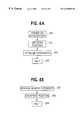
- FIGS. 6A through 6Eare program flow charts of the microcontroller program which controls operation of the motion platform in accordance with the invention.
- the motion platform 10includes a base 12 and a top 14 for supporting a user module (not shown).
- the user modulemay be a flight simulator module, an entertainment ride film module, a game module or any other desired type of module pod or body designed to simulate a real world device or vehicle.
- the base 12 and the top 14are generally rectangular.
- One of skill in the art, however,will readily recognize that either or both of the top and the base may have different cross-sectional shapes, such as circles, rectangles, hexagons and the like.
- the top 14 and the base 12preferably are formed from a single piece of metal, bent into the rectangular configuration shown in FIG. 1 .
- the top 14 and the base 12are preferably composed of an aluminum alloy, which reduces the overall weight of the motion platform relative to conventional motion platforms made of steel.
- Standard aluminum alloyin standard mill sizes, provides an adequate strength-to-weight ratio, well above required safety limits for motion platforms. While weighing significantly less than steel and having excellent working characteristics, the aluminum design lends itself to automated manufacturing techniques required to produce large quantities and low cost. It will be understood, however, that the subject motion platform 10 may also be made of steel or any other material suited to the intended application.
- the top 14has a first beam 16 extending between two side arms 18 of the top 14 .
- the first beam 16may serve as a seat, with space for placement of the legs between the first beam 16 and a front arm of the top 14 .
- the first beam 16is mounted to the side arms 18 by mounting brackets 22 .
- the top 14 of the motion platform 10is completed by a rear arm 24 .
- the base 12Like the top 14 , the base 12 includes side arms 26 , a front arm 28 , and a rear arm 30 .
- the perimeter of the base 12bounds an area of generally larger cross-section than the perimeter of the top 14 , as best seen in FIG. 4 .
- a second beam 32extends between the two side arms 26 of the base 12 .
- This second beam 32is slightly elevated from the side arms 26 by stepped mounting brackets 34 .
- These bracketsmay be standard mill-shaped, U-channel brackets.
- a support membersupports the top 14 relative to the base 12 .
- the support member 36supports all of the weight of the top 14 and any attached user module.
- the support member 36includes a hollow support beam 38 , here shown as a cylindrical post, that vertically extends between a center of the first beam 16 and a center of the second beam 32 .
- the support member 36further includes fins 40 extending from an outer surface of the support beam 38 to the second beam 32 .
- the fins 40can attach either directly to the second beam 32 or, as shown in FIG. 1, to a plate 42 mounted on the second beam 32 .
- the embodiment shown in FIG. 1has four fins 40 extending to the four corners of the plate 42 .
- the fins 40reinforce the support beam 38 .
- This reinforced support beam 38provides maximum stiffness and strength to the motion platform and, in combination with a joint 44 , discussed below, supports the load of the top 14 and any additional load, such as a user and user module.
- a jointis positioned between the support beam 38 and the first beam 16 .
- the joint 44which is preferably a heavy industrial universal joint or U-joint, allows a desired degree of pitch and roll of the top of up to ⁇ 35 degrees relative to the base.
- the joint 44has a first fixed member 46 mounted to a top 48 of the support beam 32 .
- the joint 44slips inside the support beam 38 and is welded around its perimeter.
- the joint 44also has a second fixed member 50 mounted to a bottom surface 52 of the first beam 16 .
- First and second fixed members 46 and 50are generally U-shaped and are oriented 90 degrees with respect to each other about a vertical axis.
- a cross-shaped pivot member 56Interconnecting the distal ends of members 46 and 50 is a cross-shaped pivot member 56 which is rotatably mounted with respect to both members 46 and 50 .
- the joint 44provides pivot points P and P′ that enable the top 14 to move in two degrees of freedom pivot relative to the support beam 38 .
- the motion platformalso includes a pair of positioning motors 58 that rotate a pair of arm assemblies, generally indicated 60 , to enable up to a ⁇ 35 degree range of motion of the top 14 relative to a horizontal plane shown as plane X in FIGS. 2 and 3.
- the pitch, or up down, movement of the motion platform 10is shown as ⁇ in FIG. 2 .
- the front arm 20 of the top 14moves down.
- the front arm 20moves up.
- the angle ⁇is also shown in FIG. 3 to show the range or extent of roll of the top 14 of the platform 10 .
- the positioning motors 58are mounted on motor support beams 62 , which in turn extend between the second beam 32 and the rear arm 30 of the base 12 .
- the motor support beams 62elevate the positioning motors 58 above the plane of the base 12 .
- the motor support beams 62are mounted to the rear arm 30 by stepped mounting brackets 64 and attach directly to the second beam 12 .
- the positioning motors 60are high torque motors. They provide the rotary motion to rotate the arm assemblies 60 . To achieve accurate positioning of the top 14 through rotation of the arm assemblies 60 , the motors can be instantly reversed to provide braking or to provide reverse motion, as required and as will be more fully described below.
- the motion platform 10further includes a reducer gear 66 coupled between each positioning motor 58 and its respective arm assembly 60 .
- the reducer gears 66are mounted to the motor support beams 62 .
- the reducer gears 66have worm gear arrangements that reduce the speed of the positioning motors 58 to a desired rate.
- the reducer gears 66provide braking to the arm assemblies 60 to prevent the top 14 from moving under changing loads at undesirable times.
- Each arm assembly 60includes a rotating arm 68 rotatably connected at one end to the output shaft of reducer gear 66 and thus to the positioning motor 58 .
- the other end of the rotating arm 68is rotatably connected to one end of a connecting arm 70 by a rotating ball joint, or rod end, 72 .
- the other end of the connecting arm 70is connected to a lower surface of the rear arm 24 of the top 14 by another rotating ball joint, or rod end, 74 .
- the joints 72 and 74operate so that the connecting arm 70 and the rotating arm 68 provide a rotating, variable angle joint to effect displacement of the top 14 and result in various combinations of pitch and roll during use of the motion platform 10 .
- the dimensions of the arms 68 and 70 and the elevation of the positioning motor 58 and reducer gear 66 above ground levelmay be adjusted to control the maximum available pitch and roll angle.
- the rotating arm 68is rotatably connected to the output shaft of reducer gear 66 so as to be rotatable about the shaft axis a full 360 degrees.
- the ability of the rotating arm to rotate 360 degreesprovides a wider range of motion, pitch and roll, for the motion platform than possible in conventional motion platforms restricted to quadrature motion, as seen in FIG. 2 A.
- the ability to rotate 360 degreesmeans that, in a single complete rotation of the motor, the platform “reverses” direction (goes from up-down to down-up), yet the motor need not reverse direction. Reversing the direction of the motor requires more work by the motor.
- the dimensions of the rotating arm 68 and the connecting arm 70 and the elevation of the positioning motor 58 above the base 12in combination, enable this 360-degree rotation.
- the rotating arm 68 and the connecting arm 70form an obtuse angle ⁇ .
- a benefit of a start position where the arms 68 and 70 form a non-right angleis that the positioning motors 58 are required to use less power to initiate rotational movement than those operating under quadrature motion (see FIG. 2 A).
- the motion platform 10 of the present inventionmay be run with smaller, and hence, more compact, lighter and inexpensive motors 58 .
- the linkage between the motor and the platform topis at a 90-degree angle at the start position (see FIG. 2 A), and thus motor must initiate movement when it is at its highest load.
- the connecting arm 70enables static alignment of the motion platform 10 .
- the connecting arm 70is hollow and has threaded ends, which connect respectively to the rotating ball joints or rod ends 72 and 74 .
- the length of connecting arm 70may be readily adjusted by threading either or both of the joints 72 and 74 into or out of the arm until the top 14 is in the desired position relative to base 12 . In this manner, the connecting arm 70 may be used to align/level the motion platform 10 .
- the positioning motors 58operate independently. In this way, the positioning motors 58 cause rotation of their respective rotating arms 68 to achieve whatever desired pitch, roll motion or vibration effects are desired.
- the motion platform 10is thus capable of simulating real world movements by producing movement cues replicating or simulating those experienced in real world situations.
- a microcontroller 80is mounted to a lower surface of one of the motor support beams 62 .
- the microcontroller 80controls all functionality of the motion platform 10 .
- Also mounted to the lower surface of the motion support beams 62are four solid state relay and delay circuits 82 , which will be referred to as relays 82 , mounted two on each beam 62 . These pairs of relays 82 are electrically connected to the microcontroller 80 and to each of the respective positioning motors 58 .
- the relays 82allow relatively instantaneous reversal of direction and control of rotation of the positioning motors 58 .
- the motion platform 10further includes sensors.
- the sensorspreferably are infrared emitting LEDs and photo-transistors.
- First sensors 83are mounted to a top surface of each of the reducer gears 66 to sense a position of a respective rotating arm 68 .
- the first sensors 83detect when the position of the respective rotating arms 68 are in the home position, as shown in FIG. 2 .
- Lightis reflected onto the respective sensor 83 from the rotating arm 68 as the rotating arm enters the home position.
- Second sensors 85are mounted to the positioning motors 58 .
- the positioning motors 58may comprise A/C motors or DC motors, both of which have cooling fans with equally spaced blades.
- Each of the second sensors 85senses the passage of an edge of each fan blades as that edge passes in front of the sensor 85 .
- the microcontroller 80is responsive to digital input commands and to feedback signals generated by both sets of sensors 83 and 85 .
- the microcontrollercontrols the start/stop, rotational direction, rotational speed and vibration of the positioning motors 58 in response to the input command signals supplied to the microcontroller 80 and the position, speed and extent of movement information provided by the sensors 83 and 85 , as 30 will be fully described below.
- FIG. 5is a block diagram of the electrical control system of the motion platform 10 of the present invention.
- the microcontroller 80includes a central processing unit (CPU) 102 , storage in the form of ROM 104 and RAM 106 , an input interface 108 , and an output interface 110 .
- the CPU 102is preferably an 8-bit microcomputer optimized for real-time control applications.
- RAM 106serves as temporary storage, and ROM 108 stores programming associated with operation of the motion platform 10 , such as the programming associated with the flowchart shown in FIG. 6 .
- the input interface 108receives signals from sensors 82 that sense the position of the rotating arm 68 and the passage of the fan blades of the positioning motors 58 , as described above.
- the input interface 108transmits these sensor signals to the CPU 102 for processing.
- the CPU 102sends processed signals to the output interface 110 , which outputs signals to the solid state relays to drive the positioning motors 58 , as desired.
- the microcontroller 100through its output lines, controls the ON/OFF state and speed and direction of rotation of the positioning motors 114 based on sensor signals input into the microcontroller 100 .
- the relays 82switch the positioning motors 114 ON and OFF at a rapid rate which is fast enough to control both the speed and the degree of rotation of the positioning motors 114 . If it is desired to operate the motors 58 at full speed, for example, the relays 82 are turned on and kept on without interruption. If a reduced speed is desired, the relays 82 are switched on and off to supply the motors with an interrupted or pulsed input voltage. The lower the frequency of the pulse train, the slower the speed of the motor and vice-versa. In this way, by controlling the cycle of the relays 82 , the motor speed is directly regulated. Similarly, by controlling the polarity of the motor input signal through the relays, the direction of rotation may be controlled.
- the motorscan be caused to move in a stepwise or interrupted manner at any desired rate or degree, thereby imparting any number of desired vibration effects to the top 14 of the platform 10 .
- the motion platform 10also includes a power supply 116 adapted to be connected to a suitable A/C power source 118 to provide power to the microcontroller 100 .
- the motion platform 10is adapted to receive command signals from an external command signal input unit 120 , such as a computer terminal or other ascii device capable of transmitting and receiving ascii characters, that electrically communicates with the CPU 102 through the interface input unit 108 .
- Data parameters and operational commandsmay be supplied by the input source 120 in accordance with any desired sequence to produce a pattern or programmed sequence of movement of the top 14 of platform 10 relative to base 12 .
- Such data and operational commandsinclude: home-straight and level (H), pitch angle positive (P), pitch angle negative (N), acceleration (A, roll angle right (R), roll angle left (L), set speed (SP and SR) for each motor, set vibration (VP and VR) for each motor, status (Q), and ON/OFF (T).
- the motion platformreceives all its commands from the external input unit 120 .
- the external input unit 120may consist of a joystick or controller operated by a player (or “rider”) to produce signals recognizable by the microcontroller's CPU 102 .
- the external input unit 120may consist of a programmed computer or date storage device capable of producing a running sequence of commands to cause the top 14 of the platform 10 to move in accordance with the desired motion sequence for the particular application.
- the microcontroller 100needs to know two essential things. First, it needs to know what motion is desired. Second, it needs to know what movement of the platform has occurred to verify that the commands will be properly synchronized with the platform position.
- the first requirementis satisfied by the receipt of input commands from external input unit 120 as recognized by input interface 108 and CPU 102 of the microcontroller 80 .
- the second requirementis provided by the sensors 83 and 85 .
- Sensors 83each produce a pulse when a fan blade of the motor passes within proximity of the sensor. The number of pulses indicates the amount of rotation of the motor shaft and, thus, the extent of movement of the connecting arm assembly 60 . The frequency of the pulses indicates motor speed.
- the microcontrollercan recognize the speed and extent of movement of each motor and can compute the nature and degree of motion undergone by top 14 relative to base 12 .
- FIGS. 6A-6EThe essential control sequences performed by microcontroller 80 in accordance 30 with the present invention are shown in FIGS. 6A-6E.
- a power-on initialization procedureis performed in accordance with the flow diagram of FIG. 6 A.
- the initialization procedureensures that the motion platform 10 is level and that the microcontroller 80 is ready to receive interrupts from other control routines.
- the power source 116 of motion platform 10is turned ON. With the power ON, commands are sent by the CPU through the output interface 110 to the relays 82 of motors 58 . This causes the motors 58 to move, causing the rotating arms 68 to move past their respective arm position sensors 83 .
- the microcontrollerdetects the signal indicating passage of the arm through this “zero set” position and then begins to count the pulses from the motor fan blade sensor 85 .
- the predetermined number of pulseshas been received to indicate that the arm has been moved to the “home” position corresponding to the level or horizontal orientation of the top 14
- all other interruptsare initialized, as represented by step 204 , and the motor and CPU are placed in the halt mode 206 .
- halt mode 206the power to the system is ON, the top of the platform is steady and level, and the system is ready to receive motion commands.
- FIG. 6Billustrates the data interface interrupt sequence, which is the primary control sequence or loop for the system in accordance with the present invention.
- a data interface interrupt 208will occur when the CPU 102 receives data or character input signals from the external control unit 120 , such as a computer or other device capable of supplying ascii characters.
- the data interface interruptqueries whether the CPU 102 has received a valid command or input signal from the external input unit 120 that corresponds to built in parameters stored in RAM 106 .
- these commandsinclude home-straight and level (H), pitch angle positive (P), pitch angle negative (N), acceleration (A), roll angle right (R), roll angle left (L), set speed (SP and SR) for each motor, set vibration (VP and VR) of each motor, status (Q), and ON/OFF (T).
- step 212If the answer to this query is NO, then the CPU 102 sends an error response in step 212 , and the loop halts in step 214 . If the CPU 102 has received a valid command, then the command is echoed in step 216 . The loop then queries in step 218 whether additional ascii characters representing parameters of the command are required. For example, if a set speed command SP or SR is received, the system will need to know what particular speed is desired. The system is programmed to recognize a three-digit numerical value from 0 to 999 to indicate a desired speed from zero to the maximum speed of the motors 58 .
- the interruptanswers NO and proceeds to step 220 .
- the CPU 102conducts a status request, checking to verify that the command corresponds to a status command, namely H, Q, or T, each of which require only a single command without further specifying parameters. If the response to the status request is YES, then, in step 222 , the CPU 102 reports the status and proceeds to a halt mode in step 224 . If, on the other hand, the response to the status request query is NO, then, in step 226 , an error response is sent before proceeding to a halt in step 224 .
- step 218a parameters requirement is recognized, then a retrieve sequence is initiated in step 228 to get the complete parameter from the CPU.
- the CPU 102then checks to see if the retrieved parameter is valid in step 230 . For example, if the system is set to look for a numerical value between 0 and 999, a valid parameter would be any number in that range. If the answer is NO, then an error response is sent in step 226 , and the loop is halted in step 224 . If the parameter is valid, however, the parameter is set in step 232 .
- the CPU 102then checks for an immediate command in step 234 .
- the immediate commandsrequire action or movement of the platform and include commands P, N, R, and L. If the command is not an immediate command, then the interrupt loop is again halted at step 224 . If an immediate command is detected, then the timer interrupt is set in step 236 , and, thereafter, the loop is halted in step 224 .
- the timer interrupt routineshown in FIG. 6C, is used to set the motor/s speed/direction/ON-OFF status, according to commands in the form of data signals received from the external input unit 120 .
- a speed inquiryis first performed in step 240 . If this speed inquiry response is YES, then the motor speed is set in step 242 , and a motor flag is generated in step 244 to indicate to the CPU what the motor is doing.
- the programthen continues to perform a vibration inquiry in step 246 . If the response to the speed inquiry in step 240 is NO, the program proceeds directly to the vibration inquiry in step 246 .
- step 246If the response to the vibration inquiry is YES in step 246 , then a motor Speed/Direction ON/OFF command is produced in step 248 , and a motor flag is generated in step 250 to indicate what the motor is doing. The program then proceeds to a halt in step 252 to await the next interrupt. If the response to the vibration inquiry in step 246 is NO, then the program proceeds directly to the halt mode in step 252 , as shown.
- the microcontroller 102also runs an M 1 /M 2 (first motor/second motor) sensor interrupt routine, as shown in FIG. 6 D.
- This routinemonitors the second sensors 85 that detect passage of the fan blades of the positioning motors 58 .
- the pulse count and pulse frequencyprovide extent of motion and speed information to the CPU, as described above.
- a counter in the CPU 102is advanced when the sensor detects passage of a fan blade.
- the routineinquires whether a preprogrammed terminal count has been reached at step 258 .
- the preprogrammed terminal countis determined based on how many revolution of the positioning motor are desired to move the rotating arm into the correct position to achieve the desired pitch angle or roll angle of the top of the motion platform.
- the routineproceeds to step 260 where the motor is stopped, and the motor status is set. Then the routine proceeds to a halt status in step 262 . If the terminal count has not been reached at step 258 , then the routine proceeds directly to the halt status in step 262 .
- the microcontroller 100also runs a M 1 H/M 2 H sensor interrupt routine, as shown in FIG. 6 E.
- This sequenceis based on the recognition of the fact that a single shaft rotation of each of the motors 58 is integrally related to rotation of each of the connecting arms 68 .
- twelve pulses of sensor 85will signal one rotation of the motor shaft. From this, it can be appreciated that for each rotation of the arm 68 , and then for each pulse of sensor 83 , the number of pulses from the motor fan blade must be an even multiple of twelve. If the fan blade pulse count is not an integral multiple of twelve, the system will recognize that it is out of synchronism and the counters must be reset to re-calibrate the system.
- the M 1 H/M 2 H sensor interrupt sequence of FIG. 6Eaccomplishes such re-calibration on initiation of the interrupt at step 264 , performing a modulus twelve comparison of the counts of sensors 83 and 85 , as described above, and resetting the sensor counts when necessary in step 266 before returning to a sequence halt mode in step 268 .
- the microcontroller 100is thus able to control pitch, roll, speed and vibration movements of the motion platform 10 reliably, economically and efficiently.
- the motion platformis therefore uniquely adaptable to any number of entertainment and commercial simulator applications under any suitable manual or computer control as may be desired depending on the preferences of the end user.
Landscapes
- Engineering & Computer Science (AREA)
- Theoretical Computer Science (AREA)
- Aviation & Aerospace Engineering (AREA)
- Business, Economics & Management (AREA)
- Physics & Mathematics (AREA)
- Educational Administration (AREA)
- Educational Technology (AREA)
- General Physics & Mathematics (AREA)
- Control Of Position Or Direction (AREA)
Abstract
Description
Claims (30)
Priority Applications (1)
| Application Number | Priority Date | Filing Date | Title |
|---|---|---|---|
| US09/086,676US6445960B1 (en) | 1998-05-29 | 1998-05-29 | Electric motion platform and a control system for controlling the same |
Applications Claiming Priority (1)
| Application Number | Priority Date | Filing Date | Title |
|---|---|---|---|
| US09/086,676US6445960B1 (en) | 1998-05-29 | 1998-05-29 | Electric motion platform and a control system for controlling the same |
Publications (2)
| Publication Number | Publication Date |
|---|---|
| US20020045955A1 US20020045955A1 (en) | 2002-04-18 |
| US6445960B1true US6445960B1 (en) | 2002-09-03 |
Family
ID=22200140
Family Applications (1)
| Application Number | Title | Priority Date | Filing Date |
|---|---|---|---|
| US09/086,676Expired - Fee RelatedUS6445960B1 (en) | 1998-05-29 | 1998-05-29 | Electric motion platform and a control system for controlling the same |
Country Status (1)
| Country | Link |
|---|---|
| US (1) | US6445960B1 (en) |
Cited By (51)
| Publication number | Priority date | Publication date | Assignee | Title |
|---|---|---|---|---|
| US20020164560A1 (en)* | 2001-05-04 | 2002-11-07 | Ronbotics Corporation | Acceleration sensitive electric motion platform and a control system for controlling the same |
| US20030102724A1 (en)* | 2001-11-02 | 2003-06-05 | Roy Shambhu N. | Single motor, multi-axis stage |
| US6634885B2 (en)* | 2000-01-20 | 2003-10-21 | Fidelity Flight Simulation, Inc. | Flight simulators |
| US20030219701A1 (en)* | 2000-05-12 | 2003-11-27 | Zeier Bruce E. | Simulator for aircraft flight training |
| US20040003655A1 (en)* | 2002-05-03 | 2004-01-08 | Kevin Kemp | Vehicle testing apparatus for measuring a propensity of a vehicle to roll over |
| US20040024418A1 (en)* | 2000-11-03 | 2004-02-05 | Irion Klaus M. | Simulator apparatus with at least two degrees of freedom of movement for an instrument |
| US6733293B2 (en)* | 2001-01-26 | 2004-05-11 | Provision Entertainment, Inc. | Personal simulator |
| US6796908B2 (en) | 2001-06-14 | 2004-09-28 | Creative Kingdoms, Llc | Interactive dark ride |
| US20060145575A1 (en)* | 2005-01-05 | 2006-07-06 | Abrams Jeffrey H | Control system for movable storage units |
| US20070122793A1 (en)* | 2005-11-30 | 2007-05-31 | Gauthier Orban | Actuated support platform for video system |
| US20070272904A1 (en)* | 2003-10-03 | 2007-11-29 | Letourneau Technologies, Inc. | Vehicle for materials handling and other insdustrial uses |
| US20080058110A1 (en)* | 2006-08-14 | 2008-03-06 | Chiu-Ku Chen | Structure of a horse riding machine |
| US20080141824A1 (en)* | 2006-10-26 | 2008-06-19 | Barry Lynn Wood | Rotational motion-positioning apparatus |
| US20080286726A1 (en)* | 2007-05-16 | 2008-11-20 | Bennett David G | Motion simulator and method |
| US20090186746A1 (en)* | 2008-01-21 | 2009-07-23 | John Pandolfo | Wave Motion Exercise Apparatus and Method |
| US20090246741A1 (en)* | 2008-01-09 | 2009-10-01 | Mark Soodeen | Modular flight control structure |
| US20100057307A1 (en)* | 2008-09-03 | 2010-03-04 | Caterpillar Inc. | Electrically adjustable control interface |
| US20100125029A1 (en)* | 2008-11-20 | 2010-05-20 | Inner Body Fitness & Wellness | Sway Capable Stationary Bicycle Base |
| US20100159800A1 (en)* | 2007-04-27 | 2010-06-24 | O'connor Stacy Lynn | Toy track set and relay segments |
| US20100273132A1 (en)* | 2006-08-18 | 2010-10-28 | Zen Technologies Ltd. | Motion platform system |
| US20100273394A1 (en)* | 2007-04-27 | 2010-10-28 | O'connor Stacy L | Toy track set and relay segments |
| US20100291833A1 (en)* | 2007-04-27 | 2010-11-18 | O'connor Stacy L | Toy track set and relay segments |
| US20110092132A1 (en)* | 2007-04-27 | 2011-04-21 | O'connor Stacy Lynn | Toy track set and relay segments |
| US20110124265A1 (en)* | 2007-04-27 | 2011-05-26 | O'connor Stacy Lynn | Toy track set and relay segments |
| US20110177873A1 (en)* | 2010-01-15 | 2011-07-21 | Joseph Daniel Sebelia | Potential Energy Assisted Motion Simulator Mechanism and Method |
| US8089458B2 (en) | 2000-02-22 | 2012-01-03 | Creative Kingdoms, Llc | Toy devices and methods for providing an interactive play experience |
| US8151660B2 (en) | 2007-02-23 | 2012-04-10 | RPY Motion, Inc. | Three axes rotational motion-positioning apparatus |
| US8226493B2 (en) | 2002-08-01 | 2012-07-24 | Creative Kingdoms, Llc | Interactive play devices for water play attractions |
| US20120267504A1 (en)* | 2009-06-16 | 2012-10-25 | Zen Technologies Limited | Motion platform system |
| US8475275B2 (en) | 2000-02-22 | 2013-07-02 | Creative Kingdoms, Llc | Interactive toys and games connecting physical and virtual play environments |
| US8585142B2 (en) | 2010-11-12 | 2013-11-19 | MediaMotion, Inc. | Motion seat systems and methods of implementing motion in seats |
| US8608535B2 (en) | 2002-04-05 | 2013-12-17 | Mq Gaming, Llc | Systems and methods for providing an interactive game |
| US8702515B2 (en) | 2002-04-05 | 2014-04-22 | Mq Gaming, Llc | Multi-platform gaming system using RFID-tagged toys |
| US8708821B2 (en) | 2000-02-22 | 2014-04-29 | Creative Kingdoms, Llc | Systems and methods for providing interactive game play |
| US20140157916A1 (en)* | 2012-12-03 | 2014-06-12 | Dynamic Motion Systems, GmbH | Motion Simulation System and Associated Methods |
| US8753165B2 (en) | 2000-10-20 | 2014-06-17 | Mq Gaming, Llc | Wireless toy systems and methods for interactive entertainment |
| US8758136B2 (en) | 1999-02-26 | 2014-06-24 | Mq Gaming, Llc | Multi-platform gaming systems and methods |
| US8827709B1 (en) | 2008-05-08 | 2014-09-09 | ACME Worldwide Enterprises, Inc. | Dynamic motion seat |
| USD737870S1 (en)* | 2014-01-21 | 2015-09-01 | Robert Kevin Houston | Three dimensional motion platform |
| US20160176001A1 (en)* | 2013-08-06 | 2016-06-23 | C.M.S. S.P.A. | Workpiece holding apparatus |
| US9446319B2 (en) | 2003-03-25 | 2016-09-20 | Mq Gaming, Llc | Interactive gaming toy |
| US9513168B2 (en) | 2014-09-23 | 2016-12-06 | Utah State University Research Foundation | Linear-motion stage |
| US9536446B2 (en) | 2012-12-03 | 2017-01-03 | Dynamic Motion Group Gmbh | Motion simulation system controller and associated methods |
| US9675894B2 (en) | 2012-12-03 | 2017-06-13 | Dynamic Motion Group Gmbh | Amusement park elevator drop ride system and associated methods |
| US20170216998A1 (en)* | 2014-08-06 | 2017-08-03 | C.M.S. S.P.A. | System for supporting a workpiece |
| US10093483B2 (en) | 2016-05-23 | 2018-10-09 | Hilmot LLC | Roller system having spaced apart external rotor motor |
| US10668395B1 (en)* | 2018-12-19 | 2020-06-02 | Motion Device Inc. | Motion simulator |
| US11204296B2 (en)* | 2019-07-26 | 2021-12-21 | Chuhan WANG | Horizontal instrument, a supporting device and a method for adjusting the bearing surface of the supporting device to be horizontal |
| US11260311B2 (en)* | 2019-08-21 | 2022-03-01 | Universal City Studios Llc | Resistance control systems and methods for amusement attractions |
| US11286115B2 (en) | 2019-08-13 | 2022-03-29 | Hilmot LLC | Conveyor with extended motor configuration |
| US11328620B2 (en)* | 2015-05-15 | 2022-05-10 | Motion Metrics Limited | System and method for physical activity performance analysis |
Families Citing this family (8)
| Publication number | Priority date | Publication date | Assignee | Title |
|---|---|---|---|---|
| CN107293177A (en)* | 2017-08-15 | 2017-10-24 | 科盾科技股份有限公司北京分公司 | A kind of analogue simulation trainer |
| CN108542163B (en)* | 2018-06-15 | 2024-04-26 | 北京影达技术开发有限公司 | Dynamic platform capable of horizontally rotating and horizontal initial positioning method |
| CN209204628U (en)* | 2018-09-30 | 2019-08-06 | 广州数祺数字科技有限公司 | Multidimensional seat motion platform |
| CN109143869B (en)* | 2018-10-16 | 2021-07-06 | 沈阳工业大学 | A Synchronous Control System of Recurrent Wavelet Neural Network Compensator for H-shaped Platform |
| CN109443437B (en)* | 2018-12-08 | 2023-11-14 | 宁波宏志机器人科技有限公司 | Outside-line detection equipment for bent pipe |
| CN113110072B (en)* | 2021-06-15 | 2021-09-03 | 深圳联和智慧科技有限公司 | Unmanned aerial vehicle residual power real-time monitoring method and system based on smart lamp post |
| CN114383014B (en)* | 2021-12-24 | 2024-05-24 | 威刚科技(苏州)有限公司 | Control method of multimedia device |
| CN117262613B (en)* | 2023-10-25 | 2024-05-24 | 广东速捷精密设备有限公司 | Frequency vibration amplifying device and related system |
Citations (16)
| Publication number | Priority date | Publication date | Assignee | Title |
|---|---|---|---|---|
| US3675927A (en) | 1970-06-10 | 1972-07-11 | Gottlieb & Co D | Two-player pinball machine |
| US4650190A (en) | 1983-11-09 | 1987-03-17 | Hans Geiger | Flipper game with varying degrees of difficulty |
| US5112049A (en) | 1989-08-10 | 1992-05-12 | Premier Technology | Pinball machine having a play field which is changed during play |
| US5237887A (en)* | 1991-07-01 | 1993-08-24 | Rockwell International Corporation | Straight line mechanism |
| US5294172A (en) | 1991-09-12 | 1994-03-15 | Dubus Susan E | Child's food tray with see-through enclosed interactive activity chamber |
| US5353242A (en)* | 1988-12-28 | 1994-10-04 | Veda Incorporated | Motion base control process and operator perceptual simulator |
| US5611731A (en) | 1995-09-08 | 1997-03-18 | Thrustmaster, Inc. | Video pinball machine controller having an optical accelerometer for detecting slide and tilt |
| US5772513A (en) | 1994-08-17 | 1998-06-30 | Konami Co., Ltd. | Apparatus for simulatively rotating a playing box of a simulation game machine |
| US5901612A (en)* | 1997-12-15 | 1999-05-11 | Letovsky; Howard | Dual axis mechanically actuated motion platform |
| US5952796A (en)* | 1996-02-23 | 1999-09-14 | Colgate; James E. | Cobots |
| US5954508A (en)* | 1997-08-20 | 1999-09-21 | Interactive Motion Systems | Portable and compact motion simulator |
| US5980255A (en)* | 1998-03-16 | 1999-11-09 | Cae Electronics Ltd. | Seat for motion simulator and method of motion simulation |
| US6077078A (en)* | 1996-12-27 | 2000-06-20 | Thomson-Csf | Motion simulator device with at least three degrees of freedom |
| US6095926A (en)* | 1998-05-01 | 2000-08-01 | Universal Studios, Inc. | Amusement ride vehicle |
| US6132314A (en) | 1997-05-23 | 2000-10-17 | Namco Limited | Operational input device for simulator |
| US6142877A (en) | 1996-11-22 | 2000-11-07 | Kabushiki Kaisha Sega Enterprises | Game device |
- 1998
- 1998-05-29USUS09/086,676patent/US6445960B1/ennot_activeExpired - Fee Related
Patent Citations (16)
| Publication number | Priority date | Publication date | Assignee | Title |
|---|---|---|---|---|
| US3675927A (en) | 1970-06-10 | 1972-07-11 | Gottlieb & Co D | Two-player pinball machine |
| US4650190A (en) | 1983-11-09 | 1987-03-17 | Hans Geiger | Flipper game with varying degrees of difficulty |
| US5353242A (en)* | 1988-12-28 | 1994-10-04 | Veda Incorporated | Motion base control process and operator perceptual simulator |
| US5112049A (en) | 1989-08-10 | 1992-05-12 | Premier Technology | Pinball machine having a play field which is changed during play |
| US5237887A (en)* | 1991-07-01 | 1993-08-24 | Rockwell International Corporation | Straight line mechanism |
| US5294172A (en) | 1991-09-12 | 1994-03-15 | Dubus Susan E | Child's food tray with see-through enclosed interactive activity chamber |
| US5772513A (en) | 1994-08-17 | 1998-06-30 | Konami Co., Ltd. | Apparatus for simulatively rotating a playing box of a simulation game machine |
| US5611731A (en) | 1995-09-08 | 1997-03-18 | Thrustmaster, Inc. | Video pinball machine controller having an optical accelerometer for detecting slide and tilt |
| US5952796A (en)* | 1996-02-23 | 1999-09-14 | Colgate; James E. | Cobots |
| US6142877A (en) | 1996-11-22 | 2000-11-07 | Kabushiki Kaisha Sega Enterprises | Game device |
| US6077078A (en)* | 1996-12-27 | 2000-06-20 | Thomson-Csf | Motion simulator device with at least three degrees of freedom |
| US6132314A (en) | 1997-05-23 | 2000-10-17 | Namco Limited | Operational input device for simulator |
| US5954508A (en)* | 1997-08-20 | 1999-09-21 | Interactive Motion Systems | Portable and compact motion simulator |
| US5901612A (en)* | 1997-12-15 | 1999-05-11 | Letovsky; Howard | Dual axis mechanically actuated motion platform |
| US5980255A (en)* | 1998-03-16 | 1999-11-09 | Cae Electronics Ltd. | Seat for motion simulator and method of motion simulation |
| US6095926A (en)* | 1998-05-01 | 2000-08-01 | Universal Studios, Inc. | Amusement ride vehicle |
Non-Patent Citations (24)
| Title |
|---|
| Adventure Quest Brochure, "Now" (pre-1998). |
| Adventure Quest, LLC. Brochure, "Personal Motion Theatre M-4" (pre-1998). |
| Astro Game Products, Inc. Brochure, "Interactive 3D Viper Flight simulator" (pre-1998). |
| Evans & Sutherland Web Page, "Cyber Fighter" at http://www.es.com/Products/Edutain/cyberfighter.html (Nov. 3, 1997). |
| Flight Avionics Brochure, "New '98 Premiering at IAAPA" (1998). |
| Letovsky Dynamics News Bulletin, "News In Motion", vol. 1 (1997). |
| MaxFlight Corporation Interactive Ride System Brochure, "VR2002 Roller Coaster" (pre-1998). |
| MaxFlight Corporation Interactive Ride Systems Brochure, "Get Ready for Some SeriousMotion-Introducing The Next Generation in Motion Technology" (pre-1998). |
| MaxFlight Corporation Interactive Ride Systems Brochure, "VR2000 Flight Simulator" (pre-1998). |
| MaxFlight Corporation Interactive Ride Systems Brochure, "Get Ready for Some SeriousMotion—Introducing The Next Generation in Motion Technology" (pre-1998). |
| Moog Brochure, "Moog Electric Motion Simulators" (pre-1998). |
| Motionbase Brochure, "Interactive leisure simulators, Electrical motion platforms, Visual display systems, Multiple seat motion rides" (Motionbase plc 1997). |
| Namco America, Inc. Brochure, "Final Furlong" (1997). |
| Ronbotics Corporation Motion Ride "CoasterRider X-Press" (1999). |
| Sarnicola Simulation Systems, Inc. Advertising Materials (pre-1998). |
| Servos & Simulation, Inc. Brochure "Electric Motion System High Angle Two Degrees of Freedom" (1997). |
| Servos & Simulation, Inc. Brochure "Two Degrees of Freedom Electric Motion System Model 710-2" (1997). |
| Servos & Simulation, Inc. Brochure, "Electric Motion System Two Degrees of Freedom Model 710LP-2" (1997). |
| Servos & Simulation, Inc. Brochure, "Six Degrees of Freedom Electric Motion System Model 710-6-2000" (1997). |
| Servous & Simulation, Inc. Brochure Three Degrees of Freedom Electric Motion System Model 710-3-2000 (1997). |
| Stricor, Inc. Brochure, "Xtreme-Descent II" (pre-1998). |
| Thompson Entertainment News Bulletin, "Unreal", vol. 3 (1997). |
| Winble, Inc. Brochure, "Winble Ride Machine "Wave'" (pre-1998). |
| Winble, Inc. Brochure, "Winble Ride Machine ‘Wave’" (pre-1998). |
Cited By (137)
| Publication number | Priority date | Publication date | Assignee | Title |
|---|---|---|---|---|
| US9731194B2 (en) | 1999-02-26 | 2017-08-15 | Mq Gaming, Llc | Multi-platform gaming systems and methods |
| US8758136B2 (en) | 1999-02-26 | 2014-06-24 | Mq Gaming, Llc | Multi-platform gaming systems and methods |
| US8888576B2 (en) | 1999-02-26 | 2014-11-18 | Mq Gaming, Llc | Multi-media interactive play system |
| US10300374B2 (en) | 1999-02-26 | 2019-05-28 | Mq Gaming, Llc | Multi-platform gaming systems and methods |
| US9186585B2 (en) | 1999-02-26 | 2015-11-17 | Mq Gaming, Llc | Multi-platform gaming systems and methods |
| US9861887B1 (en) | 1999-02-26 | 2018-01-09 | Mq Gaming, Llc | Multi-platform gaming systems and methods |
| US9468854B2 (en) | 1999-02-26 | 2016-10-18 | Mq Gaming, Llc | Multi-platform gaming systems and methods |
| US6634885B2 (en)* | 2000-01-20 | 2003-10-21 | Fidelity Flight Simulation, Inc. | Flight simulators |
| US9149717B2 (en) | 2000-02-22 | 2015-10-06 | Mq Gaming, Llc | Dual-range wireless interactive entertainment device |
| US10307671B2 (en) | 2000-02-22 | 2019-06-04 | Mq Gaming, Llc | Interactive entertainment system |
| US9579568B2 (en) | 2000-02-22 | 2017-02-28 | Mq Gaming, Llc | Dual-range wireless interactive entertainment device |
| US9474962B2 (en) | 2000-02-22 | 2016-10-25 | Mq Gaming, Llc | Interactive entertainment system |
| US9814973B2 (en) | 2000-02-22 | 2017-11-14 | Mq Gaming, Llc | Interactive entertainment system |
| US10188953B2 (en) | 2000-02-22 | 2019-01-29 | Mq Gaming, Llc | Dual-range wireless interactive entertainment device |
| US8089458B2 (en) | 2000-02-22 | 2012-01-03 | Creative Kingdoms, Llc | Toy devices and methods for providing an interactive play experience |
| US8915785B2 (en) | 2000-02-22 | 2014-12-23 | Creative Kingdoms, Llc | Interactive entertainment system |
| US8164567B1 (en) | 2000-02-22 | 2012-04-24 | Creative Kingdoms, Llc | Motion-sensitive game controller with optional display screen |
| US8814688B2 (en) | 2000-02-22 | 2014-08-26 | Creative Kingdoms, Llc | Customizable toy for playing a wireless interactive game having both physical and virtual elements |
| US8790180B2 (en) | 2000-02-22 | 2014-07-29 | Creative Kingdoms, Llc | Interactive game and associated wireless toy |
| US9713766B2 (en) | 2000-02-22 | 2017-07-25 | Mq Gaming, Llc | Dual-range wireless interactive entertainment device |
| US8708821B2 (en) | 2000-02-22 | 2014-04-29 | Creative Kingdoms, Llc | Systems and methods for providing interactive game play |
| US8686579B2 (en) | 2000-02-22 | 2014-04-01 | Creative Kingdoms, Llc | Dual-range wireless controller |
| US8531050B2 (en) | 2000-02-22 | 2013-09-10 | Creative Kingdoms, Llc | Wirelessly powered gaming device |
| US8491389B2 (en) | 2000-02-22 | 2013-07-23 | Creative Kingdoms, Llc. | Motion-sensitive input device and interactive gaming system |
| US8475275B2 (en) | 2000-02-22 | 2013-07-02 | Creative Kingdoms, Llc | Interactive toys and games connecting physical and virtual play environments |
| US8368648B2 (en) | 2000-02-22 | 2013-02-05 | Creative Kingdoms, Llc | Portable interactive toy with radio frequency tracking device |
| US8184097B1 (en) | 2000-02-22 | 2012-05-22 | Creative Kingdoms, Llc | Interactive gaming system and method using motion-sensitive input device |
| US8169406B2 (en) | 2000-02-22 | 2012-05-01 | Creative Kingdoms, Llc | Motion-sensitive wand controller for a game |
| US20030219701A1 (en)* | 2000-05-12 | 2003-11-27 | Zeier Bruce E. | Simulator for aircraft flight training |
| US8961260B2 (en) | 2000-10-20 | 2015-02-24 | Mq Gaming, Llc | Toy incorporating RFID tracking device |
| US9480929B2 (en) | 2000-10-20 | 2016-11-01 | Mq Gaming, Llc | Toy incorporating RFID tag |
| US9931578B2 (en) | 2000-10-20 | 2018-04-03 | Mq Gaming, Llc | Toy incorporating RFID tag |
| US10307683B2 (en) | 2000-10-20 | 2019-06-04 | Mq Gaming, Llc | Toy incorporating RFID tag |
| US8753165B2 (en) | 2000-10-20 | 2014-06-17 | Mq Gaming, Llc | Wireless toy systems and methods for interactive entertainment |
| US9320976B2 (en) | 2000-10-20 | 2016-04-26 | Mq Gaming, Llc | Wireless toy systems and methods for interactive entertainment |
| US20040024418A1 (en)* | 2000-11-03 | 2004-02-05 | Irion Klaus M. | Simulator apparatus with at least two degrees of freedom of movement for an instrument |
| US6786727B2 (en)* | 2000-11-03 | 2004-09-07 | Karl Storz Gmbh & Co. Kg | Simulator apparatus with at least two degrees of freedom of movement for an instrument |
| US6733293B2 (en)* | 2001-01-26 | 2004-05-11 | Provision Entertainment, Inc. | Personal simulator |
| US8248367B1 (en) | 2001-02-22 | 2012-08-21 | Creative Kingdoms, Llc | Wireless gaming system combining both physical and virtual play elements |
| US9393491B2 (en) | 2001-02-22 | 2016-07-19 | Mq Gaming, Llc | Wireless entertainment device, system, and method |
| US10179283B2 (en) | 2001-02-22 | 2019-01-15 | Mq Gaming, Llc | Wireless entertainment device, system, and method |
| US8711094B2 (en) | 2001-02-22 | 2014-04-29 | Creative Kingdoms, Llc | Portable gaming device and gaming system combining both physical and virtual play elements |
| US8384668B2 (en) | 2001-02-22 | 2013-02-26 | Creative Kingdoms, Llc | Portable gaming device and gaming system combining both physical and virtual play elements |
| US9162148B2 (en) | 2001-02-22 | 2015-10-20 | Mq Gaming, Llc | Wireless entertainment device, system, and method |
| US10758818B2 (en) | 2001-02-22 | 2020-09-01 | Mq Gaming, Llc | Wireless entertainment device, system, and method |
| US9737797B2 (en) | 2001-02-22 | 2017-08-22 | Mq Gaming, Llc | Wireless entertainment device, system, and method |
| US8913011B2 (en) | 2001-02-22 | 2014-12-16 | Creative Kingdoms, Llc | Wireless entertainment device, system, and method |
| US20020164560A1 (en)* | 2001-05-04 | 2002-11-07 | Ronbotics Corporation | Acceleration sensitive electric motion platform and a control system for controlling the same |
| US6796908B2 (en) | 2001-06-14 | 2004-09-28 | Creative Kingdoms, Llc | Interactive dark ride |
| US6740998B2 (en)* | 2001-11-02 | 2004-05-25 | Advantest Corporation | Single motor, multi-axis stage |
| US20030102724A1 (en)* | 2001-11-02 | 2003-06-05 | Roy Shambhu N. | Single motor, multi-axis stage |
| US8827810B2 (en) | 2002-04-05 | 2014-09-09 | Mq Gaming, Llc | Methods for providing interactive entertainment |
| US9616334B2 (en) | 2002-04-05 | 2017-04-11 | Mq Gaming, Llc | Multi-platform gaming system using RFID-tagged toys |
| US8702515B2 (en) | 2002-04-05 | 2014-04-22 | Mq Gaming, Llc | Multi-platform gaming system using RFID-tagged toys |
| US10010790B2 (en) | 2002-04-05 | 2018-07-03 | Mq Gaming, Llc | System and method for playing an interactive game |
| US9463380B2 (en) | 2002-04-05 | 2016-10-11 | Mq Gaming, Llc | System and method for playing an interactive game |
| US8608535B2 (en) | 2002-04-05 | 2013-12-17 | Mq Gaming, Llc | Systems and methods for providing an interactive game |
| US9272206B2 (en) | 2002-04-05 | 2016-03-01 | Mq Gaming, Llc | System and method for playing an interactive game |
| US10478719B2 (en) | 2002-04-05 | 2019-11-19 | Mq Gaming, Llc | Methods and systems for providing personalized interactive entertainment |
| US10507387B2 (en) | 2002-04-05 | 2019-12-17 | Mq Gaming, Llc | System and method for playing an interactive game |
| US11278796B2 (en) | 2002-04-05 | 2022-03-22 | Mq Gaming, Llc | Methods and systems for providing personalized interactive entertainment |
| US7058488B2 (en)* | 2002-05-03 | 2006-06-06 | Burke E. Porter Machinery Company | Vehicle testing apparatus for measuring a propensity of a vehicle to roll over |
| US20040003655A1 (en)* | 2002-05-03 | 2004-01-08 | Kevin Kemp | Vehicle testing apparatus for measuring a propensity of a vehicle to roll over |
| US8226493B2 (en) | 2002-08-01 | 2012-07-24 | Creative Kingdoms, Llc | Interactive play devices for water play attractions |
| US9393500B2 (en) | 2003-03-25 | 2016-07-19 | Mq Gaming, Llc | Wireless interactive game having both physical and virtual elements |
| US9993724B2 (en) | 2003-03-25 | 2018-06-12 | Mq Gaming, Llc | Interactive gaming toy |
| US11052309B2 (en) | 2003-03-25 | 2021-07-06 | Mq Gaming, Llc | Wireless interactive game having both physical and virtual elements |
| US9446319B2 (en) | 2003-03-25 | 2016-09-20 | Mq Gaming, Llc | Interactive gaming toy |
| US9707478B2 (en) | 2003-03-25 | 2017-07-18 | Mq Gaming, Llc | Motion-sensitive controller and associated gaming applications |
| US10583357B2 (en) | 2003-03-25 | 2020-03-10 | Mq Gaming, Llc | Interactive gaming toy |
| US8961312B2 (en) | 2003-03-25 | 2015-02-24 | Creative Kingdoms, Llc | Motion-sensitive controller and associated gaming applications |
| US9039533B2 (en) | 2003-03-25 | 2015-05-26 | Creative Kingdoms, Llc | Wireless interactive game having both physical and virtual elements |
| US10369463B2 (en) | 2003-03-25 | 2019-08-06 | Mq Gaming, Llc | Wireless interactive game having both physical and virtual elements |
| US9770652B2 (en) | 2003-03-25 | 2017-09-26 | Mq Gaming, Llc | Wireless interactive game having both physical and virtual elements |
| US8373659B2 (en) | 2003-03-25 | 2013-02-12 | Creative Kingdoms, Llc | Wirelessly-powered toy for gaming |
| US10022624B2 (en) | 2003-03-25 | 2018-07-17 | Mq Gaming, Llc | Wireless interactive game having both physical and virtual elements |
| US20070272904A1 (en)* | 2003-10-03 | 2007-11-29 | Letourneau Technologies, Inc. | Vehicle for materials handling and other insdustrial uses |
| US7318580B2 (en)* | 2003-10-03 | 2008-01-15 | Letourneau Technologies, Inc. | Vehicle for materials handling and other industrial uses |
| US9675878B2 (en) | 2004-09-29 | 2017-06-13 | Mq Gaming, Llc | System and method for playing a virtual game by sensing physical movements |
| US20060145575A1 (en)* | 2005-01-05 | 2006-07-06 | Abrams Jeffrey H | Control system for movable storage units |
| US20070122793A1 (en)* | 2005-11-30 | 2007-05-31 | Gauthier Orban | Actuated support platform for video system |
| US8454366B2 (en) | 2005-11-30 | 2013-06-04 | D-Box Technologies Inc. | Actuated support platform for video system |
| US20080058110A1 (en)* | 2006-08-14 | 2008-03-06 | Chiu-Ku Chen | Structure of a horse riding machine |
| US7448953B2 (en)* | 2006-08-14 | 2008-11-11 | Chiu-Ku Chen | Structure of a horse riding machine |
| US20100273132A1 (en)* | 2006-08-18 | 2010-10-28 | Zen Technologies Ltd. | Motion platform system |
| US8403673B2 (en)* | 2006-08-18 | 2013-03-26 | Zen Technologies Ltd. | Motion platform system |
| US20080141824A1 (en)* | 2006-10-26 | 2008-06-19 | Barry Lynn Wood | Rotational motion-positioning apparatus |
| US8141452B2 (en) | 2006-10-26 | 2012-03-27 | Barry Lynn Wood | Rotational motion-positioning apparatus |
| US8151660B2 (en) | 2007-02-23 | 2012-04-10 | RPY Motion, Inc. | Three axes rotational motion-positioning apparatus |
| US20100159800A1 (en)* | 2007-04-27 | 2010-06-24 | O'connor Stacy Lynn | Toy track set and relay segments |
| US9504926B2 (en) | 2007-04-27 | 2016-11-29 | Mattel, Inc. | Toy track set and relay segments |
| US20100291833A1 (en)* | 2007-04-27 | 2010-11-18 | O'connor Stacy L | Toy track set and relay segments |
| US20110124265A1 (en)* | 2007-04-27 | 2011-05-26 | O'connor Stacy Lynn | Toy track set and relay segments |
| US20100273394A1 (en)* | 2007-04-27 | 2010-10-28 | O'connor Stacy L | Toy track set and relay segments |
| US8747180B2 (en) | 2007-04-27 | 2014-06-10 | Mattel, Inc. | Toy track set and relay segments |
| US20110092132A1 (en)* | 2007-04-27 | 2011-04-21 | O'connor Stacy Lynn | Toy track set and relay segments |
| US8382553B2 (en) | 2007-04-27 | 2013-02-26 | Mattel, Inc. | Toy track set and relay segments |
| US8801492B2 (en) | 2007-04-27 | 2014-08-12 | Mattel, Inc. | Toy track set and relay segments |
| US8690632B2 (en)* | 2007-04-27 | 2014-04-08 | Mattel, Inc. | Toy track set and relay segments |
| US20080286726A1 (en)* | 2007-05-16 | 2008-11-20 | Bennett David G | Motion simulator and method |
| US20090246741A1 (en)* | 2008-01-09 | 2009-10-01 | Mark Soodeen | Modular flight control structure |
| US20090186746A1 (en)* | 2008-01-21 | 2009-07-23 | John Pandolfo | Wave Motion Exercise Apparatus and Method |
| US8827709B1 (en) | 2008-05-08 | 2014-09-09 | ACME Worldwide Enterprises, Inc. | Dynamic motion seat |
| US10553127B1 (en) | 2008-05-08 | 2020-02-04 | ACME Worldwide Enterprises, Inc. | Dynamic motion seat |
| US12431034B1 (en) | 2008-05-08 | 2025-09-30 | ACME Worldwide Enterprises, Inc. | Dynamic motion seat |
| US12073743B1 (en) | 2008-05-08 | 2024-08-27 | ACME Worldwide Enterprises, Inc. | Dynamic motion seat |
| US11302210B1 (en) | 2008-05-08 | 2022-04-12 | ACME Worldwide Enterprises, Inc. | Dynamic motion seat |
| US20100057307A1 (en)* | 2008-09-03 | 2010-03-04 | Caterpillar Inc. | Electrically adjustable control interface |
| US8483914B2 (en) | 2008-09-03 | 2013-07-09 | Caterpillar Inc. | Electrically adjustable control interface |
| US7857732B2 (en)* | 2008-11-20 | 2010-12-28 | Gregg Stuart Nielson | Sway-capable stationary bicycle |
| US20100125029A1 (en)* | 2008-11-20 | 2010-05-20 | Inner Body Fitness & Wellness | Sway Capable Stationary Bicycle Base |
| US20120267504A1 (en)* | 2009-06-16 | 2012-10-25 | Zen Technologies Limited | Motion platform system |
| US10373513B2 (en)* | 2009-06-16 | 2019-08-06 | Zen Technologies Limited | Motion platform system |
| US20110177873A1 (en)* | 2010-01-15 | 2011-07-21 | Joseph Daniel Sebelia | Potential Energy Assisted Motion Simulator Mechanism and Method |
| US8585142B2 (en) | 2010-11-12 | 2013-11-19 | MediaMotion, Inc. | Motion seat systems and methods of implementing motion in seats |
| US20140157916A1 (en)* | 2012-12-03 | 2014-06-12 | Dynamic Motion Systems, GmbH | Motion Simulation System and Associated Methods |
| US9259657B2 (en)* | 2012-12-03 | 2016-02-16 | Dynamic Motion Group Gmbh | Motion simulation system and associated methods |
| US9536446B2 (en) | 2012-12-03 | 2017-01-03 | Dynamic Motion Group Gmbh | Motion simulation system controller and associated methods |
| US9675894B2 (en) | 2012-12-03 | 2017-06-13 | Dynamic Motion Group Gmbh | Amusement park elevator drop ride system and associated methods |
| US10283008B2 (en)* | 2012-12-03 | 2019-05-07 | Dynamic Motion Group Gmbh | Motion simulation system controller and associated methods |
| US20160176001A1 (en)* | 2013-08-06 | 2016-06-23 | C.M.S. S.P.A. | Workpiece holding apparatus |
| USD737870S1 (en)* | 2014-01-21 | 2015-09-01 | Robert Kevin Houston | Three dimensional motion platform |
| US10562157B2 (en)* | 2014-08-06 | 2020-02-18 | C.M.S. S.P.A. | System for supporting a workpiece |
| US20170216998A1 (en)* | 2014-08-06 | 2017-08-03 | C.M.S. S.P.A. | System for supporting a workpiece |
| US9879974B2 (en) | 2014-09-23 | 2018-01-30 | Utah State University | Linear-motion stage |
| US9513168B2 (en) | 2014-09-23 | 2016-12-06 | Utah State University Research Foundation | Linear-motion stage |
| US20220230556A1 (en)* | 2015-05-15 | 2022-07-21 | Motion Metrics Limited | System and Method for Physical Activity Performance Analysis |
| US11328620B2 (en)* | 2015-05-15 | 2022-05-10 | Motion Metrics Limited | System and method for physical activity performance analysis |
| US20220270510A1 (en)* | 2015-05-15 | 2022-08-25 | Motion Metrics Limited | System and Method for Physical Activity Performance Analysis |
| US11996002B2 (en)* | 2015-05-15 | 2024-05-28 | Motion Metrics Limited | System and method for physical activity performance analysis |
| US20240274031A1 (en)* | 2015-05-15 | 2024-08-15 | Motion Metrics Limited | System and Method for Physical Activity Performance Analysis |
| US10093483B2 (en) | 2016-05-23 | 2018-10-09 | Hilmot LLC | Roller system having spaced apart external rotor motor |
| US10668395B1 (en)* | 2018-12-19 | 2020-06-02 | Motion Device Inc. | Motion simulator |
| US11204296B2 (en)* | 2019-07-26 | 2021-12-21 | Chuhan WANG | Horizontal instrument, a supporting device and a method for adjusting the bearing surface of the supporting device to be horizontal |
| US11286115B2 (en) | 2019-08-13 | 2022-03-29 | Hilmot LLC | Conveyor with extended motor configuration |
| US11260311B2 (en)* | 2019-08-21 | 2022-03-01 | Universal City Studios Llc | Resistance control systems and methods for amusement attractions |
| US11684862B2 (en) | 2019-08-21 | 2023-06-27 | Universal City Studios Llc | Resistance control systems and methods for amusement attractions |
Also Published As
| Publication number | Publication date |
|---|---|
| US20020045955A1 (en) | 2002-04-18 |
Similar Documents
| Publication | Publication Date | Title |
|---|---|---|
| US6445960B1 (en) | Electric motion platform and a control system for controlling the same | |
| US20020164560A1 (en) | Acceleration sensitive electric motion platform and a control system for controlling the same | |
| US6371853B1 (en) | Motion pinball game | |
| US6286441B1 (en) | Height adjustable work surface and control therefor | |
| US8410732B2 (en) | Programmable robot and user interface | |
| CA2262211C (en) | Tiltable platform | |
| US5474520A (en) | Apparatus for producing multiple motions | |
| US5752834A (en) | Motion/force simulators with six or three degrees of freedom | |
| US5720594A (en) | Fan oscillating in two axes | |
| US20060242851A1 (en) | Dual axis single motor platform adjustments system | |
| JPH0573150A (en) | Virtual pivot controller for six degrees of freedom | |
| EP0704039B1 (en) | Manual control system for camera mountings | |
| EP0701851B1 (en) | An apparatus for rotating a playing box of a simulation game machine | |
| JP4623614B2 (en) | Balance function training device | |
| US6402625B2 (en) | Motion linkage apparatus | |
| EP0697229B1 (en) | An apparatus for moving a playing box of a simulation game machine | |
| JPH0750412B2 (en) | Robot controller | |
| WO1995004959A1 (en) | Second generation six-degree-of-freedom virtual pivot hand controller | |
| JP2019130047A (en) | Balance exercise apparatus | |
| JP2007082915A (en) | Balance training equipment | |
| KR101422073B1 (en) | Swing plate device and apparatus for virtual golf simulation using the same | |
| CN206913177U (en) | A kind of highly emulated robot arm and robot | |
| KR102457392B1 (en) | Excercise Device for Upper Limb Rehabilitation | |
| CN108943017B (en) | Robot head rotating structure | |
| JP3678576B2 (en) | Horizontal / tilt adjustment device |
Legal Events
| Date | Code | Title | Description |
|---|---|---|---|
| AS | Assignment | Owner name:RONBOTICS CORPORATION, VIRGINIA Free format text:ASSIGNMENT OF ASSIGNORS INTEREST;ASSIGNOR:BORTA, RONALD T.;REEL/FRAME:009203/0863 Effective date:19980528 | |
| AS | Assignment | Owner name:RONBOTICS CORPORATION, VIRGINIA Free format text:CHANGE OF ADDRESS;ASSIGNOR:RONBOTICS CORPORATION;REEL/FRAME:012783/0409 Effective date:20020412 | |
| AS | Assignment | Owner name:BRANCH BANKING AND TRUST CO. OF VA, VIRGINIA Free format text:SECURITY INTEREST;ASSIGNOR:RONBOTICS CORPORATION;REEL/FRAME:013392/0176 Effective date:20000724 | |
| AS | Assignment | Owner name:X-MALIG ASSOCIATES, LLC, VIRGINIA Free format text:SECURITY AGREEMENT;ASSIGNOR:BRANCH BANKING & TRUST CO. OF VA;REEL/FRAME:013563/0041 Effective date:20021203 | |
| REMI | Maintenance fee reminder mailed | ||
| FPAY | Fee payment | Year of fee payment:4 | |
| SULP | Surcharge for late payment | ||
| REMI | Maintenance fee reminder mailed | ||
| LAPS | Lapse for failure to pay maintenance fees | ||
| STCH | Information on status: patent discontinuation | Free format text:PATENT EXPIRED DUE TO NONPAYMENT OF MAINTENANCE FEES UNDER 37 CFR 1.362 | |
| FP | Lapsed due to failure to pay maintenance fee | Effective date:20100903 |