US6445376B2 - Alternative power for a portable computer via solar cells - Google Patents
Alternative power for a portable computer via solar cellsDownload PDFInfo
- Publication number
- US6445376B2 US6445376B2US09/932,743US93274301AUS6445376B2US 6445376 B2US6445376 B2US 6445376B2US 93274301 AUS93274301 AUS 93274301AUS 6445376 B2US6445376 B2US 6445376B2
- Authority
- US
- United States
- Prior art keywords
- light
- solar cells
- light source
- display screen
- display panel
- Prior art date
- Legal status (The legal status is an assumption and is not a legal conclusion. Google has not performed a legal analysis and makes no representation as to the accuracy of the status listed.)
- Expired - Lifetime
Links
Images


Classifications
- G—PHYSICS
- G06—COMPUTING OR CALCULATING; COUNTING
- G06F—ELECTRIC DIGITAL DATA PROCESSING
- G06F1/00—Details not covered by groups G06F3/00 - G06F13/00 and G06F21/00
- G06F1/16—Constructional details or arrangements
- G06F1/1613—Constructional details or arrangements for portable computers
- G06F1/1633—Constructional details or arrangements of portable computers not specific to the type of enclosures covered by groups G06F1/1615 - G06F1/1626
- G06F1/1635—Details related to the integration of battery packs and other power supplies such as fuel cells or integrated AC adapter
- G—PHYSICS
- G06—COMPUTING OR CALCULATING; COUNTING
- G06F—ELECTRIC DIGITAL DATA PROCESSING
- G06F1/00—Details not covered by groups G06F3/00 - G06F13/00 and G06F21/00
- G06F1/16—Constructional details or arrangements
- G06F1/1613—Constructional details or arrangements for portable computers
- G06F1/1615—Constructional details or arrangements for portable computers with several enclosures having relative motions, each enclosure supporting at least one I/O or computing function
- G06F1/1616—Constructional details or arrangements for portable computers with several enclosures having relative motions, each enclosure supporting at least one I/O or computing function with folding flat displays, e.g. laptop computers or notebooks having a clamshell configuration, with body parts pivoting to an open position around an axis parallel to the plane they define in closed position
- G—PHYSICS
- G06—COMPUTING OR CALCULATING; COUNTING
- G06F—ELECTRIC DIGITAL DATA PROCESSING
- G06F1/00—Details not covered by groups G06F3/00 - G06F13/00 and G06F21/00
- G06F1/16—Constructional details or arrangements
- G06F1/1613—Constructional details or arrangements for portable computers
- G06F1/1633—Constructional details or arrangements of portable computers not specific to the type of enclosures covered by groups G06F1/1615 - G06F1/1626
- G06F1/1637—Details related to the display arrangement, including those related to the mounting of the display in the housing
- G—PHYSICS
- G06—COMPUTING OR CALCULATING; COUNTING
- G06F—ELECTRIC DIGITAL DATA PROCESSING
- G06F1/00—Details not covered by groups G06F3/00 - G06F13/00 and G06F21/00
- G06F1/26—Power supply means, e.g. regulation thereof
- G—PHYSICS
- G09—EDUCATION; CRYPTOGRAPHY; DISPLAY; ADVERTISING; SEALS
- G09G—ARRANGEMENTS OR CIRCUITS FOR CONTROL OF INDICATING DEVICES USING STATIC MEANS TO PRESENT VARIABLE INFORMATION
- G09G3/00—Control arrangements or circuits, of interest only in connection with visual indicators other than cathode-ray tubes
Definitions
- the present inventionrelates generally to the use of power from solar cells in connection with laptop, portable, and/or notebook computers. More particularly, the present invention relates to the manner in which solar cells can be used effectively in the electrical power system of such a computer.
- the present inventionseeks to remedy these deficiencies by incorporating solar cells into a portable computer to provide an alternate, supplemental source of power.
- solar cellsare incorporated into the display screen assembly of a notebook computer in an unobtrusive and efficient manner. With such a configuration, the notebook computer maintains its portability and functionality, while lengthening the amount of time that the notebook computer can be used without being charged.
- the solar cellsprovide an alternative source of power to help with the charging and powering of the power source in a portable computer.
- FIG. 1is a drawing of a notebook computer showing an embodiment of the present invention.
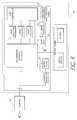
- FIG. 2is a block diagram of the sources of power in one embodiment of the present invention, where the battery can be powered by either an external source, or by solar power.
- FIG. 3is a block diagram of the sources of power in another embodiment of the present invention, where the solar cells are used to provide power to a specific component of the notebook computer.
- FIG. 4is a cross-sectional view of a fliptop display screen of the notebook computer of FIG. 1 showing a light source with associated solar cells for supplying light to a lightpipe that illuminates an LCD display.
- FIG. 5is a modified close-up view of the lower portion of FIG. 4, showing the light source and an alternative embodiment of an associated array of solar cells.
- FIG. 6is a modified close-up view of the lower portion of FIG. 4 showing a light source coupled to a lightpipe with planar arrays of solar cells positioned on either side of the light source.
- FIG. 7is a modified close-up view of the lower portion of FIG. 5, with solar cells mounted on one side of the light source.
- FIG. 8is a cross-sectional view of a fliptop display screen of the notebook computer of FIG. 1 showing an array of solar cells positioned opposite the light pipe.
- FIG. 1is a perspective view of a notebook computer 10 , which includes a display panel 11 and a chassis 12 .
- the chassis 12includes a rechargeable battery 13 and an external power plug 14 .
- the power plug 14is the port into which a power cord connected to an external power source (e.g., an AC to DC transformer) is inserted.
- an external power sourcee.g., an AC to DC transformer
- the rechargeable battery 13is recharged as needed, and the computer 10 is also powered by the external source.
- the display panel 11includes a display screen 16 of some type, such as an LCD display screen, and also has mounted therein a light source 15 for delivering light to a lightpipe (not shown in FIG. 1) as is known in the art (e.g., U.S. Pat. No. 5,050,946, the specification of which is hereby incorporated by reference).
- the display panel 11may in accordance with one embodiment of the present invention include an array of solar cells 55 .
- solar cellsmay be amorphous thin film solar cells, and may be positioned in one of the ways described more fully below.
- FIG. 2is a block diagram of the electrical power system of the notebook computer of one embodiment of the present invention.
- the computer 30(which typically includes a microprocessor as CPU, associated chipset, display screen, and other logic) is capable of receiving power from a number of sources. For example, when the plug 14 is connected to an external power source, the power converter 22 performs any power conversions that may be necessary, and the computer 30 is then powered by this external source. At the same time, the rechargeable battery 13 is also recharged (if necessary) by the external power source. And when the external power source is not available, the computer 30 is powered by the rechargeable battery 13 . In one embodiment, these components may operate as described in U.S. Pat. No. 5,532,524, which is hereby fully incorporated by reference.
- solar cells 25are also shown in FIG. 2 . These solar cells 25 provide a direct current (DC) power source that is integrated into the electrical power system of FIG. 2 . When the solar cells 25 receive light energy, this energy is converted into electric potential which may then be coupled to the other power sources and/or used in the electrical power system of FIG. 2 . The electric potential from the solar cells 25 can be used to help recharge the DC battery 13 , thereby prolonging the overall life of the rechargeable battery 13 before a full recharge is needed.
- DCdirect current
- the electrical power systemis configured so that the solar cells 25 are used to provide power to a particular portion of the notebook computer, such as one DC component (e.g., floppy disk drive) within the notebook computer 30 , as shown in FIG. 3 .
- the use of the solar cells 25 to supply power to one power-consuming component 27 of the notebook computerwill ease the load on the rechargeable battery 13 , thereby prolonging the life of battery 13 .
- the rechargeable battery 13can also be linked to the linear regulator 26 and used to supplement the power supplied by the solar cells 25 when the solar cells do not provide a sufficient amount of power to the component 27 .
- the solar cells 25can help supply power to an AC component, such as the backlight inverter for the display screen.
- an AC componentsuch as the backlight inverter for the display screen.
- Such an embodimentwould be useful because the display screen is one of the largest consumers of power, and relieving the battery 13 of the burden of supplying power to the display screen (even partially) will significantly prolong battery life.
- using the solar cells 25 to supply additional or supplemental power to an AC componentis not as efficient because of the energy lost converting the DC power from the solar cells 25 to the AC power required by such a component.
- the LCD display screen 115 contained within housing 110includes an LCD panel 120 , a cylindrical light source 125 and a light pipe 130 .
- the light source 125extends across an elongated cavity 150 adjacent to the lower edge of display screen 115 .
- the aperture 126 of the light source 125is aligned adjacent to an edge of the light pipe 130 .
- the light pipe 130is immediately adjacent to the back surface 121 of the LCD panel 120 .
- Some light sources 125do not use a reflector at all, because it can complicate the difficult task of achieving approximately uniform light intensity at all points on the LCD panel 120 . Finally, light that escapes through the LCD panel 120 that does not travel in the direction of the viewer's eye is not optimal.
- the region around the light source 125has significant light energy that is not effectively used in providing a screen display. It is often at least partially wasted, and thus represents an inefficient use of scarce battery power.
- the present inventionproposes capture of escaping and otherwise wasted light.
- thisis done by placing solar cells adjacent to the light source 125 .
- thiscan be done by surrounding the surface of light source 125 , except for aperture 126 , with a closely fitting, curved array of solar cells 135 .
- This arrayallows the solar cells to be incorporated in the cavity 150 in an unobtrusive manner and so that the useful size of the display screen is not reduced.
- This approachcan be made effective. However, it may require a close fit of the solar cells 135 with the light source 125 , which can be difficult or expensive to manufacture or assemble.
- FIG. 5An alternative configuration appears in FIG. 5 .
- solar cells 137are applied to the inner surface of housing 110 where it curves to form the lower side 111 of housing 110 .
- the shape required for the solar cells 137 to fit the inner housing surfacemay be difficult or expensive to manufacture.
- FIGS. 6 and 7show two further alternative configurations that employ more commonly available planar arrays of solar cells.
- FIG. 6shows a pair of planar solar cell arrays 139 , 140 arranged to lie adjacent opposed sides of the light source 125 .
- Neither array 139 , 140affects aperture 126 .
- FIG. 7shows a single planar array 141 of solar cells placed opposite the aperture 126 . It will be recognized that other configurations of such planar arrays are possible, including a pair of planar arrays joined at one edge with a 90% or other angle between them or three planar arrays joined to form a through shape to partially surround the light source 125 .
- FIG. 8shows yet another embodiment, where solar cells 142 are positioned on the side of the display screen opposite the lightpipe.
- light that reaches the opposite side of the display screenis captured by solar cells 142 .
- this lightcould be reflected back into the light pipe, in some situations this solution has drawbacks. For example, when the light is reflected back into the light pipe, the display intensity may not be uniform, thereby compromising display quality. For this reason, this light is often wasted, and not reflected back into the light pipe. By placing the solar cells 142 as shown in FIG. 8, this light can be used.
- FIGS. 5-8are cylindrical, it should be understood that light sources or backlights having a different construction and/or shape would also be capable of being effectively used in the present invention.
- present inventionhas been shown and described with respect to preferred embodiments, various changes and modifications that are obvious to a person skilled in the art to which the invention pertains, even if not shown or specifically described herein, are deemed to lie within the spirit and scope of the invention and the following claims.
Landscapes
- Engineering & Computer Science (AREA)
- Theoretical Computer Science (AREA)
- Computer Hardware Design (AREA)
- Physics & Mathematics (AREA)
- General Physics & Mathematics (AREA)
- General Engineering & Computer Science (AREA)
- Human Computer Interaction (AREA)
- Power Engineering (AREA)
- Mathematical Physics (AREA)
- Power Sources (AREA)
- Devices For Indicating Variable Information By Combining Individual Elements (AREA)
Abstract
Description
Claims (29)
Priority Applications (1)
| Application Number | Priority Date | Filing Date | Title |
|---|---|---|---|
| US09/932,743US6445376B2 (en) | 1997-09-12 | 2001-08-17 | Alternative power for a portable computer via solar cells |
Applications Claiming Priority (2)
| Application Number | Priority Date | Filing Date | Title |
|---|---|---|---|
| US08/928,888US6300944B1 (en) | 1997-09-12 | 1997-09-12 | Alternative power for a portable computer via solar cells |
| US09/932,743US6445376B2 (en) | 1997-09-12 | 2001-08-17 | Alternative power for a portable computer via solar cells |
Related Parent Applications (1)
| Application Number | Title | Priority Date | Filing Date |
|---|---|---|---|
| US08/928,888ContinuationUS6300944B1 (en) | 1997-09-12 | 1997-09-12 | Alternative power for a portable computer via solar cells |
Publications (2)
| Publication Number | Publication Date |
|---|---|
| US20010050680A1 US20010050680A1 (en) | 2001-12-13 |
| US6445376B2true US6445376B2 (en) | 2002-09-03 |
Family
ID=25456948
Family Applications (2)
| Application Number | Title | Priority Date | Filing Date |
|---|---|---|---|
| US08/928,888Expired - Fee RelatedUS6300944B1 (en) | 1997-09-12 | 1997-09-12 | Alternative power for a portable computer via solar cells |
| US09/932,743Expired - LifetimeUS6445376B2 (en) | 1997-09-12 | 2001-08-17 | Alternative power for a portable computer via solar cells |
Family Applications Before (1)
| Application Number | Title | Priority Date | Filing Date |
|---|---|---|---|
| US08/928,888Expired - Fee RelatedUS6300944B1 (en) | 1997-09-12 | 1997-09-12 | Alternative power for a portable computer via solar cells |
Country Status (1)
| Country | Link |
|---|---|
| US (2) | US6300944B1 (en) |
Cited By (38)
| Publication number | Priority date | Publication date | Assignee | Title |
|---|---|---|---|---|
| US20050083324A1 (en)* | 2001-12-19 | 2005-04-21 | Kazunari Ueda | Display apparatus and cellular device |
| US20050246557A1 (en)* | 2004-04-28 | 2005-11-03 | Vanzante Craig A | Laptop computer recharging using Ethernet connection |
| US20070080925A1 (en)* | 2005-10-11 | 2007-04-12 | Nokia Corporation | Power generating display device |
| CN1332286C (en)* | 2003-11-24 | 2007-08-15 | 佛山市顺德区顺达电脑厂有限公司 | Electric power administration arrangement and method for portable computers with auxiliary power supply |
| US20070252799A1 (en)* | 2006-04-28 | 2007-11-01 | Innolux Display Corp. | Liquid crystal display panel having photoelectric cell unit and mobile phone using same |
| US20090219273A1 (en)* | 2007-12-24 | 2009-09-03 | Ignis Innovation Inc. | Display system with a solar cell and device having the same |
| USD601492S1 (en)* | 2009-01-28 | 2009-10-06 | Libassi Louis F | Solar powered laptop solar panel |
| US20090256520A1 (en)* | 2008-04-09 | 2009-10-15 | Abe Frishman | Portable Notebook Computer with Selectively Exposed Solar Charging Cells |
| USD662041S1 (en)* | 2009-06-23 | 2012-06-19 | Stion Corporation | Pin striped thin film solar module for laptop personal computer |
| US8659518B2 (en) | 2005-01-28 | 2014-02-25 | Ignis Innovation Inc. | Voltage programmed pixel circuit, display system and driving method thereof |
| US8664644B2 (en) | 2001-02-16 | 2014-03-04 | Ignis Innovation Inc. | Pixel driver circuit and pixel circuit having the pixel driver circuit |
| US8743096B2 (en) | 2006-04-19 | 2014-06-03 | Ignis Innovation, Inc. | Stable driving scheme for active matrix displays |
| USD710791S1 (en)* | 2013-08-21 | 2014-08-12 | WEWI Telecommunications Inc. | Laptop having a foldable and detachable solar array |
| US8901579B2 (en) | 2011-08-03 | 2014-12-02 | Ignis Innovation Inc. | Organic light emitting diode and method of manufacturing |
| USRE45291E1 (en) | 2004-06-29 | 2014-12-16 | Ignis Innovation Inc. | Voltage-programming scheme for current-driven AMOLED displays |
| US9070775B2 (en) | 2011-08-03 | 2015-06-30 | Ignis Innovations Inc. | Thin film transistor |
| US9134825B2 (en) | 2011-05-17 | 2015-09-15 | Ignis Innovation Inc. | Systems and methods for display systems with dynamic power control |
| US9153172B2 (en) | 2004-12-07 | 2015-10-06 | Ignis Innovation Inc. | Method and system for programming and driving active matrix light emitting device pixel having a controllable supply voltage |
| US9385169B2 (en) | 2011-11-29 | 2016-07-05 | Ignis Innovation Inc. | Multi-functional active matrix organic light-emitting diode display |
| US9472138B2 (en) | 2003-09-23 | 2016-10-18 | Ignis Innovation Inc. | Pixel driver circuit with load-balance in current mirror circuit |
| US9502653B2 (en) | 2013-12-25 | 2016-11-22 | Ignis Innovation Inc. | Electrode contacts |
| US9606607B2 (en) | 2011-05-17 | 2017-03-28 | Ignis Innovation Inc. | Systems and methods for display systems with dynamic power control |
| US9818376B2 (en) | 2009-11-12 | 2017-11-14 | Ignis Innovation Inc. | Stable fast programming scheme for displays |
| US9842889B2 (en) | 2014-11-28 | 2017-12-12 | Ignis Innovation Inc. | High pixel density array architecture |
| US9934725B2 (en) | 2013-03-08 | 2018-04-03 | Ignis Innovation Inc. | Pixel circuits for AMOLED displays |
| US9952698B2 (en) | 2013-03-15 | 2018-04-24 | Ignis Innovation Inc. | Dynamic adjustment of touch resolutions on an AMOLED display |
| US10089924B2 (en) | 2011-11-29 | 2018-10-02 | Ignis Innovation Inc. | Structural and low-frequency non-uniformity compensation |
| US10163996B2 (en) | 2003-02-24 | 2018-12-25 | Ignis Innovation Inc. | Pixel having an organic light emitting diode and method of fabricating the pixel |
| US10176752B2 (en) | 2014-03-24 | 2019-01-08 | Ignis Innovation Inc. | Integrated gate driver |
| US10204540B2 (en) | 2015-10-26 | 2019-02-12 | Ignis Innovation Inc. | High density pixel pattern |
| US10373554B2 (en) | 2015-07-24 | 2019-08-06 | Ignis Innovation Inc. | Pixels and reference circuits and timing techniques |
| US10410579B2 (en) | 2015-07-24 | 2019-09-10 | Ignis Innovation Inc. | Systems and methods of hybrid calibration of bias current |
| US10586491B2 (en) | 2016-12-06 | 2020-03-10 | Ignis Innovation Inc. | Pixel circuits for mitigation of hysteresis |
| US10657895B2 (en) | 2015-07-24 | 2020-05-19 | Ignis Innovation Inc. | Pixels and reference circuits and timing techniques |
| US10714018B2 (en) | 2017-05-17 | 2020-07-14 | Ignis Innovation Inc. | System and method for loading image correction data for displays |
| US10971078B2 (en) | 2018-02-12 | 2021-04-06 | Ignis Innovation Inc. | Pixel measurement through data line |
| US10997901B2 (en) | 2014-02-28 | 2021-05-04 | Ignis Innovation Inc. | Display system |
| US11025899B2 (en) | 2017-08-11 | 2021-06-01 | Ignis Innovation Inc. | Optical correction systems and methods for correcting non-uniformity of emissive display devices |
Families Citing this family (2)
| Publication number | Priority date | Publication date | Assignee | Title |
|---|---|---|---|---|
| US6992733B1 (en)* | 1997-04-11 | 2006-01-31 | Micron Technology, Inc. | Backlighting system for an LCD |
| JP4107314B2 (en)* | 2005-03-30 | 2008-06-25 | 日本電気株式会社 | Image processing, compression, expansion, transmission, transmission, reception apparatus and method, program thereof, and display apparatus |
Citations (13)
| Publication number | Priority date | Publication date | Assignee | Title |
|---|---|---|---|---|
| US4083097A (en) | 1976-11-30 | 1978-04-11 | The United States Of America As Represented By The Administrator Of The National Aeronautics And Space Administration | Method of making encapsulated solar cell modules |
| US4563727A (en) | 1985-01-14 | 1986-01-07 | Curiel Raymond F | Self-charging solar battery |
| US4686441A (en) | 1985-03-04 | 1987-08-11 | Tor Petterson | Photo electric charger device for low power electrical device |
| US4855725A (en) | 1987-11-24 | 1989-08-08 | Fernandez Emilio A | Microprocessor based simulated book |
| US5039928A (en) | 1988-12-09 | 1991-08-13 | Semiconductor Energy Laboratory Co., Ltd. | Accumulator for portable computers |
| US5260885A (en) | 1991-08-31 | 1993-11-09 | Ma Hsi Kuang | Solar power operated computer |
| US5300874A (en) | 1989-09-29 | 1994-04-05 | Kabushiki Kaisha Toshiba | Intelligent power supply system for a portable computer |
| US5477239A (en) | 1993-11-12 | 1995-12-19 | Dell Usa, L.P. | Front lighting system for liquid crystal display |
| US5522943A (en) | 1994-12-05 | 1996-06-04 | Spencer; Jerald C. | Portable power supply |
| US5532524A (en) | 1994-05-11 | 1996-07-02 | Apple Computer, Inc. | Distributed power regulation in a portable computer to optimize heat dissipation and maximize battery run-time for various power modes |
| US5698964A (en) | 1995-10-20 | 1997-12-16 | Dell Usa, L.P. | Adaptive power battery charging apparatus |
| US5742367A (en) | 1995-05-11 | 1998-04-21 | Rohm Co., Ltd. | Liquid-crystal display device having a stacked arrangement of an LCD for displaying an image, a liquid crystal shutter, and a solar cell panel |
| US5936380A (en) | 1997-09-12 | 1999-08-10 | Micron Electronics, Inc. | Alternative power for a portable computer via solar cells |
Family Cites Families (1)
| Publication number | Priority date | Publication date | Assignee | Title |
|---|---|---|---|---|
| US5283673A (en)* | 1989-09-30 | 1994-02-01 | Kabushiki Kaisha Meitaku Shisutemu | Surface luminous source panel with areas having different reflector speck densities |
- 1997
- 1997-09-12USUS08/928,888patent/US6300944B1/ennot_activeExpired - Fee Related
- 2001
- 2001-08-17USUS09/932,743patent/US6445376B2/ennot_activeExpired - Lifetime
Patent Citations (13)
| Publication number | Priority date | Publication date | Assignee | Title |
|---|---|---|---|---|
| US4083097A (en) | 1976-11-30 | 1978-04-11 | The United States Of America As Represented By The Administrator Of The National Aeronautics And Space Administration | Method of making encapsulated solar cell modules |
| US4563727A (en) | 1985-01-14 | 1986-01-07 | Curiel Raymond F | Self-charging solar battery |
| US4686441A (en) | 1985-03-04 | 1987-08-11 | Tor Petterson | Photo electric charger device for low power electrical device |
| US4855725A (en) | 1987-11-24 | 1989-08-08 | Fernandez Emilio A | Microprocessor based simulated book |
| US5039928A (en) | 1988-12-09 | 1991-08-13 | Semiconductor Energy Laboratory Co., Ltd. | Accumulator for portable computers |
| US5300874A (en) | 1989-09-29 | 1994-04-05 | Kabushiki Kaisha Toshiba | Intelligent power supply system for a portable computer |
| US5260885A (en) | 1991-08-31 | 1993-11-09 | Ma Hsi Kuang | Solar power operated computer |
| US5477239A (en) | 1993-11-12 | 1995-12-19 | Dell Usa, L.P. | Front lighting system for liquid crystal display |
| US5532524A (en) | 1994-05-11 | 1996-07-02 | Apple Computer, Inc. | Distributed power regulation in a portable computer to optimize heat dissipation and maximize battery run-time for various power modes |
| US5522943A (en) | 1994-12-05 | 1996-06-04 | Spencer; Jerald C. | Portable power supply |
| US5742367A (en) | 1995-05-11 | 1998-04-21 | Rohm Co., Ltd. | Liquid-crystal display device having a stacked arrangement of an LCD for displaying an image, a liquid crystal shutter, and a solar cell panel |
| US5698964A (en) | 1995-10-20 | 1997-12-16 | Dell Usa, L.P. | Adaptive power battery charging apparatus |
| US5936380A (en) | 1997-09-12 | 1999-08-10 | Micron Electronics, Inc. | Alternative power for a portable computer via solar cells |
Cited By (59)
| Publication number | Priority date | Publication date | Assignee | Title |
|---|---|---|---|---|
| US8664644B2 (en) | 2001-02-16 | 2014-03-04 | Ignis Innovation Inc. | Pixel driver circuit and pixel circuit having the pixel driver circuit |
| US8890220B2 (en) | 2001-02-16 | 2014-11-18 | Ignis Innovation, Inc. | Pixel driver circuit and pixel circuit having control circuit coupled to supply voltage |
| US20050083324A1 (en)* | 2001-12-19 | 2005-04-21 | Kazunari Ueda | Display apparatus and cellular device |
| US7973810B2 (en)* | 2001-12-19 | 2011-07-05 | Panasonic Corporation | Display apparatus and cellular device |
| US10163996B2 (en) | 2003-02-24 | 2018-12-25 | Ignis Innovation Inc. | Pixel having an organic light emitting diode and method of fabricating the pixel |
| US10089929B2 (en) | 2003-09-23 | 2018-10-02 | Ignis Innovation Inc. | Pixel driver circuit with load-balance in current mirror circuit |
| US9472138B2 (en) | 2003-09-23 | 2016-10-18 | Ignis Innovation Inc. | Pixel driver circuit with load-balance in current mirror circuit |
| CN1332286C (en)* | 2003-11-24 | 2007-08-15 | 佛山市顺德区顺达电脑厂有限公司 | Electric power administration arrangement and method for portable computers with auxiliary power supply |
| US7424626B2 (en) | 2004-04-28 | 2008-09-09 | Hewlett-Packard Development Company, L.P. | Laptop computer recharging using Ethernet connection |
| US20050246557A1 (en)* | 2004-04-28 | 2005-11-03 | Vanzante Craig A | Laptop computer recharging using Ethernet connection |
| USRE47257E1 (en) | 2004-06-29 | 2019-02-26 | Ignis Innovation Inc. | Voltage-programming scheme for current-driven AMOLED displays |
| USRE45291E1 (en) | 2004-06-29 | 2014-12-16 | Ignis Innovation Inc. | Voltage-programming scheme for current-driven AMOLED displays |
| US9153172B2 (en) | 2004-12-07 | 2015-10-06 | Ignis Innovation Inc. | Method and system for programming and driving active matrix light emitting device pixel having a controllable supply voltage |
| US9728135B2 (en) | 2005-01-28 | 2017-08-08 | Ignis Innovation Inc. | Voltage programmed pixel circuit, display system and driving method thereof |
| US9373645B2 (en) | 2005-01-28 | 2016-06-21 | Ignis Innovation Inc. | Voltage programmed pixel circuit, display system and driving method thereof |
| US8659518B2 (en) | 2005-01-28 | 2014-02-25 | Ignis Innovation Inc. | Voltage programmed pixel circuit, display system and driving method thereof |
| US20070080925A1 (en)* | 2005-10-11 | 2007-04-12 | Nokia Corporation | Power generating display device |
| US9633597B2 (en) | 2006-04-19 | 2017-04-25 | Ignis Innovation Inc. | Stable driving scheme for active matrix displays |
| US10453397B2 (en) | 2006-04-19 | 2019-10-22 | Ignis Innovation Inc. | Stable driving scheme for active matrix displays |
| US10127860B2 (en) | 2006-04-19 | 2018-11-13 | Ignis Innovation Inc. | Stable driving scheme for active matrix displays |
| US8743096B2 (en) | 2006-04-19 | 2014-06-03 | Ignis Innovation, Inc. | Stable driving scheme for active matrix displays |
| US20070252799A1 (en)* | 2006-04-28 | 2007-11-01 | Innolux Display Corp. | Liquid crystal display panel having photoelectric cell unit and mobile phone using same |
| US20090219273A1 (en)* | 2007-12-24 | 2009-09-03 | Ignis Innovation Inc. | Display system with a solar cell and device having the same |
| US8334863B2 (en)* | 2007-12-24 | 2012-12-18 | Ignis Innovation Inc. | Display system with a solar cell and device having the same |
| US20090256520A1 (en)* | 2008-04-09 | 2009-10-15 | Abe Frishman | Portable Notebook Computer with Selectively Exposed Solar Charging Cells |
| USD601492S1 (en)* | 2009-01-28 | 2009-10-06 | Libassi Louis F | Solar powered laptop solar panel |
| USD662041S1 (en)* | 2009-06-23 | 2012-06-19 | Stion Corporation | Pin striped thin film solar module for laptop personal computer |
| US10685627B2 (en) | 2009-11-12 | 2020-06-16 | Ignis Innovation Inc. | Stable fast programming scheme for displays |
| US9818376B2 (en) | 2009-11-12 | 2017-11-14 | Ignis Innovation Inc. | Stable fast programming scheme for displays |
| US9606607B2 (en) | 2011-05-17 | 2017-03-28 | Ignis Innovation Inc. | Systems and methods for display systems with dynamic power control |
| US10249237B2 (en) | 2011-05-17 | 2019-04-02 | Ignis Innovation Inc. | Systems and methods for display systems with dynamic power control |
| US9134825B2 (en) | 2011-05-17 | 2015-09-15 | Ignis Innovation Inc. | Systems and methods for display systems with dynamic power control |
| US9224954B2 (en) | 2011-08-03 | 2015-12-29 | Ignis Innovation Inc. | Organic light emitting diode and method of manufacturing |
| US9070775B2 (en) | 2011-08-03 | 2015-06-30 | Ignis Innovations Inc. | Thin film transistor |
| US8901579B2 (en) | 2011-08-03 | 2014-12-02 | Ignis Innovation Inc. | Organic light emitting diode and method of manufacturing |
| US10453904B2 (en) | 2011-11-29 | 2019-10-22 | Ignis Innovation Inc. | Multi-functional active matrix organic light-emitting diode display |
| US10079269B2 (en) | 2011-11-29 | 2018-09-18 | Ignis Innovation Inc. | Multi-functional active matrix organic light-emitting diode display |
| US9385169B2 (en) | 2011-11-29 | 2016-07-05 | Ignis Innovation Inc. | Multi-functional active matrix organic light-emitting diode display |
| US10089924B2 (en) | 2011-11-29 | 2018-10-02 | Ignis Innovation Inc. | Structural and low-frequency non-uniformity compensation |
| US9818806B2 (en) | 2011-11-29 | 2017-11-14 | Ignis Innovation Inc. | Multi-functional active matrix organic light-emitting diode display |
| US9934725B2 (en) | 2013-03-08 | 2018-04-03 | Ignis Innovation Inc. | Pixel circuits for AMOLED displays |
| US9952698B2 (en) | 2013-03-15 | 2018-04-24 | Ignis Innovation Inc. | Dynamic adjustment of touch resolutions on an AMOLED display |
| USD710791S1 (en)* | 2013-08-21 | 2014-08-12 | WEWI Telecommunications Inc. | Laptop having a foldable and detachable solar array |
| US9831462B2 (en) | 2013-12-25 | 2017-11-28 | Ignis Innovation Inc. | Electrode contacts |
| US9502653B2 (en) | 2013-12-25 | 2016-11-22 | Ignis Innovation Inc. | Electrode contacts |
| US10997901B2 (en) | 2014-02-28 | 2021-05-04 | Ignis Innovation Inc. | Display system |
| US10176752B2 (en) | 2014-03-24 | 2019-01-08 | Ignis Innovation Inc. | Integrated gate driver |
| US10170522B2 (en) | 2014-11-28 | 2019-01-01 | Ignis Innovations Inc. | High pixel density array architecture |
| US9842889B2 (en) | 2014-11-28 | 2017-12-12 | Ignis Innovation Inc. | High pixel density array architecture |
| US10657895B2 (en) | 2015-07-24 | 2020-05-19 | Ignis Innovation Inc. | Pixels and reference circuits and timing techniques |
| US10410579B2 (en) | 2015-07-24 | 2019-09-10 | Ignis Innovation Inc. | Systems and methods of hybrid calibration of bias current |
| US10373554B2 (en) | 2015-07-24 | 2019-08-06 | Ignis Innovation Inc. | Pixels and reference circuits and timing techniques |
| US10204540B2 (en) | 2015-10-26 | 2019-02-12 | Ignis Innovation Inc. | High density pixel pattern |
| US10586491B2 (en) | 2016-12-06 | 2020-03-10 | Ignis Innovation Inc. | Pixel circuits for mitigation of hysteresis |
| US10714018B2 (en) | 2017-05-17 | 2020-07-14 | Ignis Innovation Inc. | System and method for loading image correction data for displays |
| US11025899B2 (en) | 2017-08-11 | 2021-06-01 | Ignis Innovation Inc. | Optical correction systems and methods for correcting non-uniformity of emissive display devices |
| US11792387B2 (en) | 2017-08-11 | 2023-10-17 | Ignis Innovation Inc. | Optical correction systems and methods for correcting non-uniformity of emissive display devices |
| US10971078B2 (en) | 2018-02-12 | 2021-04-06 | Ignis Innovation Inc. | Pixel measurement through data line |
| US11847976B2 (en) | 2018-02-12 | 2023-12-19 | Ignis Innovation Inc. | Pixel measurement through data line |
Also Published As
| Publication number | Publication date |
|---|---|
| US20010050680A1 (en) | 2001-12-13 |
| US6300944B1 (en) | 2001-10-09 |
Similar Documents
| Publication | Publication Date | Title |
|---|---|---|
| US6445376B2 (en) | Alternative power for a portable computer via solar cells | |
| US5936380A (en) | Alternative power for a portable computer via solar cells | |
| USRE41060E1 (en) | Multi-functional charger with power generating and illumination functions | |
| EP0801263A3 (en) | Rechargeable flashlight assembly with nightlight | |
| US20070052385A1 (en) | Streetlight powered by solar energy | |
| CN101299545A (en) | Portable dual-mode charger | |
| US20020088486A1 (en) | Solar-powered device for charging a battery unit of a mobile telephone handset | |
| WO2008124932A1 (en) | System for recharging battery operated portable electronic devices in case of power outage/failure | |
| US9948123B2 (en) | Portable solar power management system | |
| US20060103242A1 (en) | Uninterruptible power supply facility | |
| US20080315825A1 (en) | Self-Sustained Current Supply Device For Mobile Small Appliances | |
| US20120229072A1 (en) | Light Chargeable Notebook | |
| JP2001183620A (en) | Solar cell type liquid crystal device | |
| CN213027478U (en) | Flexible solar wireless mobile phone charger | |
| KR200215562Y1 (en) | The sun's energy use an electic charging handphone | |
| JPH0381810A (en) | Lap top type personal computer | |
| CN207184129U (en) | A kind of solar mobile bonnet of good heat dissipation effect | |
| US6686721B1 (en) | Inductive control valve using solar battery as a supplementary energy source | |
| CN222210226U (en) | Floor lamp | |
| CN213115768U (en) | Lighting system of electricity-preserving on duty tent | |
| CN220234265U (en) | Backpack battery | |
| CN211405577U (en) | Solar energy portable power source | |
| CN218386848U (en) | Portable portable power source and wearing equipment | |
| CN219227532U (en) | Portable multifunctional solar panel | |
| KR20020015493A (en) | Ac adapter for portable computer |
Legal Events
| Date | Code | Title | Description |
|---|---|---|---|
| AS | Assignment | Owner name:MICRON TECHNOLOGY, INC., IDAHO Free format text:ASSIGNMENT OF ASSIGNORS INTEREST;ASSIGNOR:MEI CALIFORNIA INC;REEL/FRAME:012232/0436 Effective date:20010322 | |
| STCF | Information on status: patent grant | Free format text:PATENTED CASE | |
| CC | Certificate of correction | ||
| CC | Certificate of correction | ||
| FEPP | Fee payment procedure | Free format text:PAYOR NUMBER ASSIGNED (ORIGINAL EVENT CODE: ASPN); ENTITY STATUS OF PATENT OWNER: LARGE ENTITY | |
| FPAY | Fee payment | Year of fee payment:4 | |
| FPAY | Fee payment | Year of fee payment:8 | |
| FPAY | Fee payment | Year of fee payment:12 | |
| AS | Assignment | Owner name:U.S. BANK NATIONAL ASSOCIATION, AS COLLATERAL AGENT, CALIFORNIA Free format text:SECURITY INTEREST;ASSIGNOR:MICRON TECHNOLOGY, INC.;REEL/FRAME:038669/0001 Effective date:20160426 Owner name:U.S. BANK NATIONAL ASSOCIATION, AS COLLATERAL AGEN Free format text:SECURITY INTEREST;ASSIGNOR:MICRON TECHNOLOGY, INC.;REEL/FRAME:038669/0001 Effective date:20160426 | |
| AS | Assignment | Owner name:MORGAN STANLEY SENIOR FUNDING, INC., AS COLLATERAL AGENT, MARYLAND Free format text:PATENT SECURITY AGREEMENT;ASSIGNOR:MICRON TECHNOLOGY, INC.;REEL/FRAME:038954/0001 Effective date:20160426 Owner name:MORGAN STANLEY SENIOR FUNDING, INC., AS COLLATERAL Free format text:PATENT SECURITY AGREEMENT;ASSIGNOR:MICRON TECHNOLOGY, INC.;REEL/FRAME:038954/0001 Effective date:20160426 | |
| AS | Assignment | Owner name:U.S. BANK NATIONAL ASSOCIATION, AS COLLATERAL AGENT, CALIFORNIA Free format text:CORRECTIVE ASSIGNMENT TO CORRECT THE REPLACE ERRONEOUSLY FILED PATENT #7358718 WITH THE CORRECT PATENT #7358178 PREVIOUSLY RECORDED ON REEL 038669 FRAME 0001. ASSIGNOR(S) HEREBY CONFIRMS THE SECURITY INTEREST;ASSIGNOR:MICRON TECHNOLOGY, INC.;REEL/FRAME:043079/0001 Effective date:20160426 Owner name:U.S. BANK NATIONAL ASSOCIATION, AS COLLATERAL AGEN Free format text:CORRECTIVE ASSIGNMENT TO CORRECT THE REPLACE ERRONEOUSLY FILED PATENT #7358718 WITH THE CORRECT PATENT #7358178 PREVIOUSLY RECORDED ON REEL 038669 FRAME 0001. ASSIGNOR(S) HEREBY CONFIRMS THE SECURITY INTEREST;ASSIGNOR:MICRON TECHNOLOGY, INC.;REEL/FRAME:043079/0001 Effective date:20160426 | |
| AS | Assignment | Owner name:MICRON TECHNOLOGY, INC., IDAHO Free format text:RELEASE BY SECURED PARTY;ASSIGNOR:U.S. BANK NATIONAL ASSOCIATION, AS COLLATERAL AGENT;REEL/FRAME:047243/0001 Effective date:20180629 | |
| AS | Assignment | Owner name:MICRON TECHNOLOGY, INC., IDAHO Free format text:RELEASE BY SECURED PARTY;ASSIGNOR:MORGAN STANLEY SENIOR FUNDING, INC., AS COLLATERAL AGENT;REEL/FRAME:050937/0001 Effective date:20190731 |