US6443894B1 - Medical diagnostic ultrasound system and method for mapping surface data for three dimensional imaging - Google Patents
Medical diagnostic ultrasound system and method for mapping surface data for three dimensional imagingDownload PDFInfo
- Publication number
- US6443894B1 US6443894B1US09/408,302US40830299AUS6443894B1US 6443894 B1US6443894 B1US 6443894B1US 40830299 AUS40830299 AUS 40830299AUS 6443894 B1US6443894 B1US 6443894B1
- Authority
- US
- United States
- Prior art keywords
- data
- boundary
- rendering
- transducer
- type
- Prior art date
- Legal status (The legal status is an assumption and is not a legal conclusion. Google has not performed a legal analysis and makes no representation as to the accuracy of the status listed.)
- Expired - Fee Related
Links
Images


Classifications
- A—HUMAN NECESSITIES
- A61—MEDICAL OR VETERINARY SCIENCE; HYGIENE
- A61B—DIAGNOSIS; SURGERY; IDENTIFICATION
- A61B8/00—Diagnosis using ultrasonic, sonic or infrasonic waves
- A61B8/44—Constructional features of the ultrasonic, sonic or infrasonic diagnostic device
- A61B8/4483—Constructional features of the ultrasonic, sonic or infrasonic diagnostic device characterised by features of the ultrasound transducer
- A61B8/4488—Constructional features of the ultrasonic, sonic or infrasonic diagnostic device characterised by features of the ultrasound transducer the transducer being a phased array
- A—HUMAN NECESSITIES
- A61—MEDICAL OR VETERINARY SCIENCE; HYGIENE
- A61B—DIAGNOSIS; SURGERY; IDENTIFICATION
- A61B5/00—Measuring for diagnostic purposes; Identification of persons
- A61B5/06—Devices, other than using radiation, for detecting or locating foreign bodies ; Determining position of diagnostic devices within or on the body of the patient
- A61B5/061—Determining position of a probe within the body employing means separate from the probe, e.g. sensing internal probe position employing impedance electrodes on the surface of the body
- A61B5/062—Determining position of a probe within the body employing means separate from the probe, e.g. sensing internal probe position employing impedance electrodes on the surface of the body using magnetic field
- A—HUMAN NECESSITIES
- A61—MEDICAL OR VETERINARY SCIENCE; HYGIENE
- A61B—DIAGNOSIS; SURGERY; IDENTIFICATION
- A61B8/00—Diagnosis using ultrasonic, sonic or infrasonic waves
- A61B8/08—Clinical applications
- A61B8/0833—Clinical applications involving detecting or locating foreign bodies or organic structures
- A—HUMAN NECESSITIES
- A61—MEDICAL OR VETERINARY SCIENCE; HYGIENE
- A61B—DIAGNOSIS; SURGERY; IDENTIFICATION
- A61B8/00—Diagnosis using ultrasonic, sonic or infrasonic waves
- A61B8/08—Clinical applications
- A61B8/0858—Clinical applications involving measuring tissue layers, e.g. skin, interfaces
- A—HUMAN NECESSITIES
- A61—MEDICAL OR VETERINARY SCIENCE; HYGIENE
- A61B—DIAGNOSIS; SURGERY; IDENTIFICATION
- A61B8/00—Diagnosis using ultrasonic, sonic or infrasonic waves
- A61B8/12—Diagnosis using ultrasonic, sonic or infrasonic waves in body cavities or body tracts, e.g. by using catheters
- A—HUMAN NECESSITIES
- A61—MEDICAL OR VETERINARY SCIENCE; HYGIENE
- A61B—DIAGNOSIS; SURGERY; IDENTIFICATION
- A61B8/00—Diagnosis using ultrasonic, sonic or infrasonic waves
- A61B8/42—Details of probe positioning or probe attachment to the patient
- A61B8/4245—Details of probe positioning or probe attachment to the patient involving determining the position of the probe, e.g. with respect to an external reference frame or to the patient
- A61B8/4254—Details of probe positioning or probe attachment to the patient involving determining the position of the probe, e.g. with respect to an external reference frame or to the patient using sensors mounted on the probe
- A—HUMAN NECESSITIES
- A61—MEDICAL OR VETERINARY SCIENCE; HYGIENE
- A61B—DIAGNOSIS; SURGERY; IDENTIFICATION
- A61B8/00—Diagnosis using ultrasonic, sonic or infrasonic waves
- A61B8/46—Ultrasonic, sonic or infrasonic diagnostic devices with special arrangements for interfacing with the operator or the patient
- A61B8/461—Displaying means of special interest
- A61B8/463—Displaying means of special interest characterised by displaying multiple images or images and diagnostic data on one display
- A—HUMAN NECESSITIES
- A61—MEDICAL OR VETERINARY SCIENCE; HYGIENE
- A61B—DIAGNOSIS; SURGERY; IDENTIFICATION
- A61B8/00—Diagnosis using ultrasonic, sonic or infrasonic waves
- A61B8/48—Diagnostic techniques
- A61B8/481—Diagnostic techniques involving the use of contrast agents, e.g. microbubbles introduced into the bloodstream
- A—HUMAN NECESSITIES
- A61—MEDICAL OR VETERINARY SCIENCE; HYGIENE
- A61B—DIAGNOSIS; SURGERY; IDENTIFICATION
- A61B8/00—Diagnosis using ultrasonic, sonic or infrasonic waves
- A61B8/48—Diagnostic techniques
- A61B8/483—Diagnostic techniques involving the acquisition of a 3D volume of data
- A—HUMAN NECESSITIES
- A61—MEDICAL OR VETERINARY SCIENCE; HYGIENE
- A61B—DIAGNOSIS; SURGERY; IDENTIFICATION
- A61B5/00—Measuring for diagnostic purposes; Identification of persons
- A61B5/06—Devices, other than using radiation, for detecting or locating foreign bodies ; Determining position of diagnostic devices within or on the body of the patient
- A61B5/065—Determining position of the probe employing exclusively positioning means located on or in the probe, e.g. using position sensors arranged on the probe
- A61B5/066—Superposing sensor position on an image of the patient, e.g. obtained by ultrasound or x-ray imaging
- A—HUMAN NECESSITIES
- A61—MEDICAL OR VETERINARY SCIENCE; HYGIENE
- A61B—DIAGNOSIS; SURGERY; IDENTIFICATION
- A61B5/00—Measuring for diagnostic purposes; Identification of persons
- A61B5/06—Devices, other than using radiation, for detecting or locating foreign bodies ; Determining position of diagnostic devices within or on the body of the patient
- A61B5/065—Determining position of the probe employing exclusively positioning means located on or in the probe, e.g. using position sensors arranged on the probe
- A61B5/067—Determining position of the probe employing exclusively positioning means located on or in the probe, e.g. using position sensors arranged on the probe using accelerometers or gyroscopes
- A—HUMAN NECESSITIES
- A61—MEDICAL OR VETERINARY SCIENCE; HYGIENE
- A61B—DIAGNOSIS; SURGERY; IDENTIFICATION
- A61B6/00—Apparatus or devices for radiation diagnosis; Apparatus or devices for radiation diagnosis combined with radiation therapy equipment
- A61B6/50—Apparatus or devices for radiation diagnosis; Apparatus or devices for radiation diagnosis combined with radiation therapy equipment specially adapted for specific body parts; specially adapted for specific clinical applications
- A61B6/503—Apparatus or devices for radiation diagnosis; Apparatus or devices for radiation diagnosis combined with radiation therapy equipment specially adapted for specific body parts; specially adapted for specific clinical applications for diagnosis of the heart
- A—HUMAN NECESSITIES
- A61—MEDICAL OR VETERINARY SCIENCE; HYGIENE
- A61B—DIAGNOSIS; SURGERY; IDENTIFICATION
- A61B6/00—Apparatus or devices for radiation diagnosis; Apparatus or devices for radiation diagnosis combined with radiation therapy equipment
- A61B6/50—Apparatus or devices for radiation diagnosis; Apparatus or devices for radiation diagnosis combined with radiation therapy equipment specially adapted for specific body parts; specially adapted for specific clinical applications
- A61B6/504—Apparatus or devices for radiation diagnosis; Apparatus or devices for radiation diagnosis combined with radiation therapy equipment specially adapted for specific body parts; specially adapted for specific clinical applications for diagnosis of blood vessels, e.g. by angiography
- A—HUMAN NECESSITIES
- A61—MEDICAL OR VETERINARY SCIENCE; HYGIENE
- A61B—DIAGNOSIS; SURGERY; IDENTIFICATION
- A61B6/00—Apparatus or devices for radiation diagnosis; Apparatus or devices for radiation diagnosis combined with radiation therapy equipment
- A61B6/54—Control of apparatus or devices for radiation diagnosis
- A61B6/541—Control of apparatus or devices for radiation diagnosis involving acquisition triggered by a physiological signal
- A—HUMAN NECESSITIES
- A61—MEDICAL OR VETERINARY SCIENCE; HYGIENE
- A61B—DIAGNOSIS; SURGERY; IDENTIFICATION
- A61B8/00—Diagnosis using ultrasonic, sonic or infrasonic waves
- A61B8/08—Clinical applications
- A61B8/0891—Clinical applications for diagnosis of blood vessels
- Y—GENERAL TAGGING OF NEW TECHNOLOGICAL DEVELOPMENTS; GENERAL TAGGING OF CROSS-SECTIONAL TECHNOLOGIES SPANNING OVER SEVERAL SECTIONS OF THE IPC; TECHNICAL SUBJECTS COVERED BY FORMER USPC CROSS-REFERENCE ART COLLECTIONS [XRACs] AND DIGESTS
- Y10—TECHNICAL SUBJECTS COVERED BY FORMER USPC
- Y10S—TECHNICAL SUBJECTS COVERED BY FORMER USPC CROSS-REFERENCE ART COLLECTIONS [XRACs] AND DIGESTS
- Y10S128/00—Surgery
- Y10S128/916—Ultrasound 3-D imaging
Definitions
- This inventionrelates to a medical diagnostic ultrasound system and method for three dimensional (3D) imaging.
- an image of structure in a bodyis rendered from data representing three dimensions.
- ultrasound data representing a volume within the bodyis collected.
- the ultrasound datacomprises B-mode or Doppler mode data.
- color Doppler datais collected in a series of frames of data representing two dimensional (2D) areas of the body.
- the frames of dataare registered relative to other frames of data.
- the imageis surface or volume rendered from the data registered to represent the volume.
- color Doppler imagesrepresent the point of view of the user as if moving through a structure within the body. The user may better appreciate the internal structure of vessels or better identify areas of stenosis.
- color Doppler datahas poor spatial resolution, so little detail about the texture of the structure is provided.
- the lighting model usedis typically chosen arbitrarily.
- the displayed structural representationshows the geometry but provides poor textural representation. For example, some plaque may not be visible or represented in the images.
- the preferred embodiment described belowincludes a method and system for mapping surface data onto a geometrical representation of a structure for 3D imaging.
- a boundary of a structureis determined from one type of data, such as Doppler energy data.
- Another type of datasuch as B-mode data, representing the boundary or a volume adjacent the boundary is extracted or identified.
- the B-mode datais then rendered as a function of the boundary, such as by texture mapping the B-mode data onto or adjacent the boundary.
- the texture mapped datamay provide texture details based on an optimally determined representation.
- a medical diagnostic ultrasound method for mapping data for three-dimensional imagingis provided.
- a boundaryis determined from a set of a first type of data representing a three dimensional region.
- An imageis rendered from a set of a second type of data representing the three-dimensional region as a function of the boundary.
- a system for performing this aspectincludes boundary and 3D image processors.
- a medical diagnostic ultrasound method for mapping data for three-dimensional imagingis provided.
- a boundaryis determined from a set of Doppler data representing a three dimensional region.
- Data from a set of B-mode data representing the three-dimensional regionis texture mapped onto the boundary.
- An imageis rendered as a function of the texture mapping.
- FIG. 1is a block diagram of one preferred embodiment of a medical diagnostic ultrasound system for 3D imaging.
- FIG. 2is side view of a catheter with an ultrasound transducer and a cardiac parameter measurement catheter extension.
- FIG. 3is a flow chart representing operation of the system of FIG. 1 .
- FIG. 4is a graphical representation of a rendered image.
- FIG. 5is a graphical perspective representation of a point of view for 3D rendering.
- FIG. 6is a cross-sectional representation of a vessel.
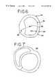
- FIG. 7is a cross-sectional representation of a heart.
- a geometric boundaryis determined from one type of data, such as ultrasound Doppler energy data.
- the texture associated with the boundary or a volume adjacent the boundaryis determined from a different type of data, such as B-mode data.
- Each of the two different types of dataare selected or optimized for their contribution to the rendered images, such as selecting different data for each of boundary detection and spatial texture mapping.
- the ultrasound system 10includes a transmit beamformer 12 , a transducer 14 , a receive beamformer 16 , a filter block 18 , a signal processor 20 and a scan converter 22 .
- the ultrasound system 10is configurable to acquire information corresponding to a plurality of two-dimensional representations or image planes of a subject for three-dimensional reconstruction. Other methods, such as those associated with a two dimensional or single element transducer array, may be used.
- the ultrasound system 10is configured to transmit, receive and process a plurality of transmit events. Each transmit event corresponds to firing an ultrasound scan line into the subject.
- the transmit beamformer 12is a digital or analog beamformer capable of generating signals at different frequencies.
- the transmit beamformercomprises the beamformer described in Cole et al., U.S. Pat. No. 5,675,554, assigned to the assignee of the present invention, the disclosure of which is incorporated herein by reference.
- the ideal output signalis defined in the frequency domain and converted to the time domain. This time domain signal is divided by the carrier to obtain the desired envelope using complex shapes for both the time domain signal and the carrier. This combination of envelope and carrier is programmed into the transmit waveformer.
- the envelopeis sampled at a relatively low frequency, and as a result of imperfections in real implementations, remnants of harmonics relating to the sampling frequency of the carrier and the base band signal may appear in the final result.
- An additional low pass filtermay be used to suppress these remnants.
- the transmit beamformer 12generates one or more excitation signals.
- Each excitation signalhas an associated center frequency.
- the center frequency of the excitation signalsis within the 1 to 15 MHz range, such as 2 MHz, and accounts for the frequency response of the transducer 14 .
- the excitation signalspreferably have non-zero bandwidth.
- the excitation signals from the transmit beamformer 12are provided to the transducer 14 .
- the transducer 14is of any construction for converting electrical energy to acoustic energy, such as the one-dimensional, multiple element arrays (e.g. the Acuson 3V2c transducer). 2D arrays, sparse 2D arrays, spiral 2D arrays [See U.S. Pat. 5,808,962], 1.5D arrays and single element transducers may be used.
- the transducercomprises multiple arrays, either in parallel or at non-zero angles with respect to each other as disclosed in U.S. application Ser. No. 08/916,585, filed Aug. 22, 1997, the disclosure of which is incorported herein by reference. In this embodiment, one array may be used for tracking motion of the other imaging array.
- the transducer 14is designed for use external or internal to the body.
- the transduceris mounted on a catheter (see U.S. Pat. No. 5,876,345, or U.S. Pat. No. 5,699,805 assigned to the assignee of the present invention, the disclosures of which are incorporated herein by reference), a transesophgeal device (see U.S. Pat. No. 6,045,508, filed Feb. 27, 1997, assigned to the assignee of the present invention, the disclosure of which is incorporated herein by reference), an endocavity device, a hand held casing or a surface mounted device.
- One or more of the elements in the transducer 14are excited by an excitation signal to produce ultrasonic acoustic waveforms.
- the transducer 14converts these excitation signals into ultrasonic energy that is directed along transmit beams into the subject, such as the body of a patient. Scattering sites within the subject, such as contrast agents or tissue in the subject, cause echo information to be returned to the transducer 14 . This echo information is converted by the transducer 14 into electrical signals that are applied to the receive beamformer 16 .
- the receive beamformer 16is of a construction known in the art, such as an analog or digital receive beamformer capable of processing signals associated with different frequencies.
- the receive beamformer 16 and the transmit beamformer 12may comprise a single device.
- the receive beamformer 16comprises the beamformer disclosed by Wright, et al. in U.S. Pat. No. 5,685,308, assigned to the assignee of the present invention and incorporated herein by reference.
- the receive beamformer 16is preferably programmable.
- the receive beamformer 16delays, apodizes and sums each electrical signal with other electrical signals.
- An ongoing stream of summed signalsrepresents the ultrasound beam or line, or portions of the lines when multiple transmit focus depths per line are used, received from the body.
- the receive beamformer 16generates in phase and quadrature (I and Q) information along one or more scan lines. Alternatively, real value signals may be generated.
- I and Q informationcorresponding to a two-dimensional representation (a plurality of scan lines) is preferably acquired before I and Q information for the next frame is acquired.
- gatingis preferably used to trigger application of the excitation signals to the transducer 14 .
- the breathing cycle or bothare utilized.
- ECG gatinga window is selected a fixed time duration after the ECG pulse maximum.
- breathing cycle gatingit is often simplest to ask the patient to hold his or her breath for the short duration of the ultrasonic scan.
- chest motioncan be recorded using a displacement sensor, and data can be selected for a portion of the breathing cycle.
- the temperature of air in the patient's nostrilsis detected.
- the receive beamformer 16passes the signals to the filter block 18 .
- the filter block 18comprises a processor, digital signal processor, ASIC, dedicated hardware or other filters, including one or both of programmable and non-programmable filters.
- the filter block 18passes information associated with a desired frequency band, such as the fundamental band using fundamental band filter 24 or a harmonic frequency band using the harmonic band filter 26 .
- the filter block 18may be included as part of the receive beamformer 16 .
- harmonicincludes sub-harmonics (e.g. 1 ⁇ 2 of the fundamental), fractional harmonics (e.g. ⁇ fraction (3/2) ⁇ of the fundamental) as well as second, third, fourth, and other higher harmonics.
- the harmonic frequency bandpreferably does not but may overlap the fundamental frequency band.
- tissue harmonic imagingno additional contrast agent is added to the target, and only the nonlinear characteristics of the tissue are relied on to create the ultrasonic image.
- Medical ultrasound imagingis typically conducted in a discrete imaging session for a given subject at a given time. For example, an imaging session can be limited to an ultrasound patient examination of a specific tissue of interest over a period of 1 ⁇ 4 to 1 hour, though other durations are possible. In this case, no additional contrast agent is introduced into the tissue at any time during the imaging session.
- the harmonic imaging technique described abovecan be used for both tissue and contrast agent harmonic imaging.
- contrast agent harmonic imagingany one of a number of ultrasound contrast agents is added to the target or subject in order to enhance the non-linear response of the tissue or fluid.
- the contrast agentsradiate ultrasonic energy at harmonics of an insonifying energy at fundamental frequencies.
- the fundamental band filter 24 and the harmonic band filter 26preferably comprise one filter that is programmable to pass different frequency bands, such as the fundamental, second or third harmonic bands.
- the filter block 18demodulates the summed signals to baseband.
- the demodulation frequencyis selected in response to the fundamental center frequency or another frequency, such as a second harmonic center frequency.
- the transmitted ultrasonic waveformsare transmitted at a 2 MHz center frequency.
- the summed signalsare then demodulated to baseband by shifting by either the fundamental 2 MHz or the second harmonic 4 MHz center frequencies (the demodulation frequency). Other center frequencies may be used. Signals associated with frequencies other than near baseband are removed by low pass filtering.
- the filter block 18provides band pass filtering.
- the signalsare demodulated to an intermediate frequency (IF)( e.g. 2 MHz) or not demodulated and a band pass filter is used.
- IFintermediate frequency
- signals associated with frequencies other than a range of frequencies centered around the desired frequency or an intermediate frequency (IF)are filtered from the summed signals.
- the demodulated or filtered signalis passed to the signal processor 20 as the complex I and Q signal, but other types of signals, such as real value signals, may be passed.
- the signal processor 20comprises one or more processors, digital signal processors, ASICs, dedicated hardware or other devices for generating Doppler or B-mode information.
- the signal processor 20comprises a Doppler processor 28 and a B-mode processor 30 .
- Each of these processorsdetects information from the received signals.
- the Doppler processor 28estimates velocity, variance of velocity and energy from the I and Q signals.
- the B-mode processor 30generates information representing the intensity (e.g. envelope, amplitude or power) of the echo signal associated with the I and Q signals.
- B-mode data, color Doppler velocity data (CDV), color Doppler energy data (CDE), Doppler Tissue data (DTI), Color Doppler Variance data, or combinations thereofare detected.
- the information generated by the signal processor 20is provided to the scan converter 22 .
- the scan converter 22includes detection steps as known in the art and described in U.S. Pat. No. 5,793,701, assigned to the assignee of the present invention.
- the scan converter 22comprises processors, digital signal processors, ASICs and/or dedicated hardware for arranging the output of the signal processor 20 into two-dimensional or three-dimensional representations or frames of image data.
- the scan converter 22outputs formatted video image data frames, such as DICOM Medical industry image standard format or a TIFF format.
- the plurality of two-dimensional representations or a single three-dimensional representationis generated.
- Each of the representationscorresponds to a receive center frequency, such as a second harmonic center frequency, a type of imaging, such as B-mode, and positional information as discussed below.
- separate frames of data for B-mode and Doppler mode dataare acquired.
- the transmission and processing for acquiring each type of datais interleaved as known in the art.
- ultrasound datamay be acquired.
- data representing perfusion of contrast agents into a region of interestis acquired, such as disclosed in U.S. application Ser. No. 09/144,843, filed Aug. 31, 1998, the disclosure of which is incorporated herein by reference.
- the perfusion datais derived from an absolute measure (e.g. measuring the concentration of contrast agents), a wash-in curve, a wash-out curve, a pulse repetition frequency, other perfusion measurements or combinations thereof.
- Other measures, including non-ultrasound measurements, of perfusionmay be used.
- tissue viability datamay be acquired.
- Tissue viability ultrasound datapreferably comprises data derived as a function of perfusion data and tissue motion data.
- a measurement of the distance of wall movementmay be derived from ultrasound data, such as from Doppler tissue motion data.
- a boundaryis defined and tracked to measure the amount of tissue motion.
- Other measures, including non-ultrasound measurements, of tissue viabilitymay be used.
- the contractility of the heartmay be measured.
- contractilityis measured as a function of the change in the heart wall thickness during a cardiac cycle.
- the wall thicknessmay be derived from B-mode or Doppler data.
- An ultrasonic contrast agentmay also be used to improve detection of wall boundaries.
- the contraction informationis thus acquired, such as for showing ischemic areas.
- the data system 37comprises a processor, digital signal processor, ASIC, dedicated hardware, other devices and combinations thereof with a sensor for acquiring one or more of different types of data.
- the data system 37comprises a CT scan, MRI, x-ray or optical system.
- the electric potential of the heartis mapped, such as with localized electrodes or with a catheter designed to measure the electrical potential on the surface of the cardiac chambers. Either the amplitude or the relative timing as a function of a reference point (e.g. the time a potential is measured relative to the electrical activation of the sino-atrial node in the right atrium of the electrical potential is measured).
- the contractility of the heartis measured either independently of or as a function of the electric potential.
- the data system 37may comprise components for measuring the stress, pressure, strain, perfusion, viability, wall motion or other parameters of a body.
- the datais aligned within a representative volume as a function of position information.
- Many approachescan be taken in aligning the data frames to provide a desired three-dimensional reconstruction. Many of the approaches provide position information associated with the orientation of one data frame relative to other data frames.
- Frames of ultrasound dataare preferably aligned as a function of acquisition with a same transducer 14 .
- the position informationsuch as from a rotatable transducer, is provided from the transducer 14 on a line 32 .
- the position informationcomprises three components of position (X, Y, Z) and three components of rotation (about X, Y, and Z).
- Other definitions of position and orientationmay be used, such as 2 known points and one origin point on each plane.
- a single element transducer(or an axially focused annular array) is mechanically scanned so as to sweep a volume or three-dimensional space.
- An example of this first methodis the method practiced for the Medison-Kretz Combison 530 (Korea). Moving parts for sweeping the volume are enclosed in a fluid filled housing. Thus, the three-dimensional space is swept by mechanically moving the transducer over two-dimensions.
- the second methodis to use a two-dimensional, sparse two-dimensional, spiral two-dimensional or 1.5 dimensional transducer array to obtain information directly.
- a sparse two-dimensional, spiral two-dimensional arraycan be used to scan electronically in any desired orientation to acquire the desired information.
- the sparse two-dimensional arrayis sub-sampled. It is generally impractical to provide a fully sampled 2D array (e.g. 64 ⁇ 64 is 4096 elements).
- An example of a sparse two-dimensional arrayis disclosed in U.S. Pat. No. 5,329,496 (Smith).
- An imaging system for use with the disclosed arrayis described in U.S. Pat. No.5,546,807 (Oxaal et al.).
- Other subsampled two-dimensional arraysinclude spiral 2D arrays, such as disclosed in U.S. Pat. No. 5,808,962.
- the third methodis to collect multiple two-dimensional image data frames associated with relative positional information using a one-dimensional transducer array.
- the two-dimensional data frames or image planesare non-coplanar, such as two or more rotationally offset planes or two or more planes offset in an elevational position.
- One dimensionis electronically scanned and another dimension is mechanically scanned by rotation, translation, or any combination thereof.
- the transduceris swept. Sweeping corresponds to rotating the transducer about an axis along the azimuth of the lens surface.
- the positional informationprovides the relative position among the data frames so that these frames may be subsequently assembled to form the desired three-dimensional reconstruction.
- Another approachis to sense position based on image motion detection, such as disclosed in MULTIPLE ULTRASOUND IMAGE REGISTRATION SYSTEM, METHOD AND TRANSDUCER, U.S. application Ser. No. 08/621,561, filed Mar. 25, 1996, U.S. application Ser. No. 08/807,498, filed Feb. 27, 1997 and U.S. application Ser. No. 08/916,585, filed Aug. 22, 1997 to Hossack et al., assigned to the assignee of the present invention, and the disclosures of which are herein incorporated by reference.
- the position informationis calculated from scan data as a function of the correlation of data.
- the rate of speckle de-correlationis measured between frames of data.
- the rate of speckle de-correlationindicates an amount of movement between the frames of data.
- Friemel et al.describes in U.S. Pat. Nos. 5,655,535 and 5,899,861 other approaches to determining the amount of motion between frames of data.
- the relative time delay between signals from two transducer elements in a 2D array in the near fieldis directly proportional to transducer velocity.
- transducer motionis measured as a function of spectral broadening. As a transducer element is translated, a fast Fourier transform is performed on data received from a given range. The resulting spectrum is a function of the transducer element geometry, the pulse repetition frequency, and the velocity of transducer movement.
- the power function of an echo signal at a single transducer elementis proportion to the elevational velocity.
- the spectral peak magnitudeis used. Comparisons of the locations of the peak magnitude locations are used to estimate elevation translation or motion. Other techniques disclosed by Friemel et al. may be used.
- magnetic position sensorsare mounted on a catheter.
- the catheteris inserted into the body. Sensors external to the body determine a position of the catheter and transducer array mounted thereon to register each frame of data relative to another frame of data. The position is determined through triangulation. The position is determined through use of a 6-D (i.e., position and orientation) magnetic position tracker, such as the 3Space Fastrack® manufactured by Polhenus, Inc., Naga manufactured by Biosense or the miniBirdTM manufactured by Ascension Technology Corp.
- the catheterincludes a transducer array that is rotated to acquire data representing a toroid volume. The position of the catheter and associated scan planes are determined from the position sensor and angle of rotation.
- Another approachis to provide a spaced arrangement of LEDs, such as infra-red LEDs, on the transducer.
- the LEDsare activated in sequence and monitored with a camera. The position and orientation is then inferred from an image of the LEDs generated by the camera.
- One such deviceis manufactured by Surgical Navigation Technologies of Broomfield, Colo.
- Still another approachis to use a spaced arrangement of microphones. See King U.S. Pat. No. 4,100,916.
- the position informationis determined from the time of flight of acoustic impulses generated by a source on the transducer to the various microphones.
- Yet another approachis to use a motorized array to collect the desired set of image data frames by precisely controlling the movement of the transducer array.
- One exampleis the Acuson V5M Transesophageal transducer, a rotating transducer.
- the rotating transducerproduces two-dimensional images at known angles of rotation.
- a lens design for such a transduceris shown in U.S. Pat. No. 5,562,096 (Hossack, et al., assigned to the assignee of the present invention).
- Another exampleis a transthoracic transducer, such as disclosed in Pini U.S. Pat. No. 5,159,931.
- the frames of different types of ultrasound dataare registered or aligned relative to each other by any of the methods described above or other methods.
- frames of B-mode dataare acquired as a function of measured position information and then frames of Doppler data are acquired as a function of the same type of position information.
- frames of harmonic B-mode data and fundamental B-mode dataare acquired as a function of the same transmissions or type of position information.
- the chances for errors in the registrationare reduced by interleaving acquisition of the different types of data.
- one or more lines or frames of Doppler dataare acquired for each line or frame of B-mode data.
- Non-ultrasound datasuch as electric potential data
- a catheter for acquiring ultrasound data and electric potential datamay include a position sensor.
- Other common reference measurementsmay be used, such as using two different devices with a same type of sensor for measuring position in the same way.
- the datais aligned as a function of correlation with other data, such as where both frames of data represent a same structure of the body.
- Other techniques for aligning non-ultrasound data with other non-ultrasound data or with ultrasound datamay be used, whether known or yet developed.
- FIG. 2shows one embodiment of a catheter 50 designed to register non-ultrasound frames of data with ultrasound frames of data.
- a device 52 for measuring electrical potential of the heart wallextends from a port 54 in the catheter 50 .
- a transducer array 56is positioned so that a portion of the device 52 (e.g. the end of the device 52 ) is within a scan plane 58 of the transducer array 56 .
- the non-ultrasound datais acquired simultaneously with ultrasound data at known points within the scan plane 58 .
- the position of the catheter 50 for registration of the ultrasound frames of datais determined using any of the techniques discussed above, such as magnetic position sensors.
- the cathetercomprises one of the catheters disclosed in U.S. Pat. No.
- the device 52is separate from the catheter 50 and the position is determined using any of the techniques discussed above, such as magnetic position sensors.
- a representation of the device 52such as a representation of the tip or transducer, may be added to the 3D or 4D rendering.
- a surface renderingis used where a representation is added.
- the position information and the ultrasound data frames and/or non-ultrasound data framesare provided to a boundary processor 34 and a 3D image processor 35 via a cable or other data link.
- the boundary processor 34 and 3D image processor 35comprise a single remote computer for real time or delayed reconstruction and rendering.
- an on-board computer and/or separate processors or computersare used.
- the processors 34 and 35comprise at least an Intel Pentium PC (400+ MHz) or SGI(O 2 or Octane for example) with a memory 36 .
- the memory 36is large, such as 128 MB RAM.
- Image data frames from the scan converter 22can be compressed using any suitable compression technique such as JPEG prior to transfer.
- the image dataAfter the image data has been received, it is decompressed. For example, 3D reconstruction is performed on a remote workstation such as the AEGIS workstation of Acuson Corporation, the assignee of the present invention.
- a remote workstationsuch as the AEGIS workstation of Acuson Corporation, the assignee of the present invention.
- the reconstruction and display of a three dimensional representationis either during the imaging session or after the imaging session.
- the boundary processor 34 and 3 D image processor 35use the image data frames and the position information to generate information for the three dimensional representation.
- Information from the two-dimensional image data framesis converted to a 3D grid, such as a preferred regularly (equal) spaced volume grid. Equal spacing allows for efficient calculations and use with low cost visualization software.
- the image data frame for a central planeis inserted at a plane aligned with the center of the volume. Working outwardly from this center plane, successive image data frames are inserted into their appropriate XYZ locations, as a function of the positional information. Once all frames have been inserted, intermediate points are calculated using three-dimensional linear interpolation techniques relying on the eight closest known data points.
- the three-dimensional image data provided by the scan converter 22is already in a 3D grid, avoiding conversion to a 3D grid.
- the processors 34 and 35use software to construct the 3D representation based on the input information discussed above.
- Various commercially available software and fixturesare available for 3D reconstruction.
- TomTec GmbH(Schschleissheim, Germany) offers software and mechanical fixtures specifically for 3D ultrasound.
- the softwareis capable of 3D reconstruction based on several different scan formats, such as rotations and freehand scanning.
- Life Imaging System Inc.(London, Ontario, Canada) also provides software and mechanical scanning fixtures for 3D ultrasound.
- VayTek Inc.(Fairfield, Iowa) produces rendering software for a 3D volumetric regularly spaced, orthogonal grid data.
- Advanced Visual Systems Inc.(Waltham, Mass.) offers an AVS5 software package for constructing and rendering 3D representations from the plurality of image data frames.
- the software for reconstruction of the 3D representationis written specifically for the system 10 described above.
- a standard languagesuch as C or C++, is used with WindowsNT® (Microsoft) and a graphics Applications Programming Interface (e.g. OpenGL® (Silicon Graphics Inc.)).
- WindowsNT®Microsoft
- OpenGL®Microsoft Graphics Inc.
- Other languages, programs, and computersmay be used.
- the frames of data and positional informationare not interpolated to the 3D grid.
- the boundary detection and rendering discussed beloware performed as a function of the frames of data and the positional information without reformatting.
- the boundary processor 34 and 3D image processor 35detect a boundary and render an image as a function of the boundary, respectively.
- steps 60data is acquired, such as the frames of ultrasound and/or non-ultrasound data or data in the 3D grid. At least two different types of data are acquired.
- the datarepresents a structure, such as a blood vessel, a heart chamber, an interface between fluid and tissue, an interface between different tissues or other identifiable interfaces.
- the boundary processor 34determines a boundary in act 62 .
- a boundary representing a section of a vesselis determined from frames of Doppler energy ultrasound data.
- One or more of various methods for determining the boundaryare used.
- the boundaryis determined as a function of a threshold.
- a thresholdis applied to the frames of data or the 3D grid of data. Any locations corresponding to data values transitioning from above to below the threshold value represent the boundary.
- an enclosed structuresuch as a vessel
- Doppler datais imaged in cross-section with Doppler data.
- a center of gravity of the enclosed structure represented by the frame of datais determined.
- the first spatial location where Doppler data is thresholded to a zero valueis selected as a boundary point.
- the boundary pointsare connected to form the boundary. This process is repeated for each frame of data to identify the boundary in three dimensions.
- the boundaryis determined as a function of the maximum gradient.
- the frames of data or data in the 3D gridis filtered along each dimension. After filtering the data, the derivative between spatial locations is determined. The derivative represents the gradient between adjacent points. The maximum gradient represents the boundary.
- a marching cubes techniqueis used.
- the datais divided into cubes with data representing each comer of a cube.
- a boundary planeif any, is determined through the cube, based on application of a threshold.
- the boundary planes of the cubesare linked together, providing a three-dimensional boundary.
- Lorensen et al.in “Marching Cubes: A High Resolution 3D Surface Reconstruction Algorithm”, Computer Graphics, Vol. 21, pp. 163-169, 1987.
- tetrahedral tessellationis used.
- the 3D spaceis divided into tetrahedrons.
- the contours associated with the tetrahedrons representing the boundaryare determined using Voronoi triangulation in 3D.
- One such techniqueis described by Boissonnat in “Shape Reconstruction from Planar Cross Sections”, Computer Vision, Graphics and Image Processing, Vol. 44, pp. 1-29, 1988.
- Another such techniqueis described by Watson in “Computer n-dimensional Delaunay Tessellation with Applications to Voronoi Polytopes”, The Computer Journal, Vol.24, No. 2, pp. 167-172, 1981.
- boundary detection techniquesmay be used.
- the boundaryis defined in response to user input, such as tracing the boundary in various 2D planes. Multiple boundary techniques may also be used.
- the detected boundariesare then averaged or otherwise combined to define a common boundary. Once the boundaries are determined, a polygon mesh is formed to represent the surface.
- An imageis then rendered as a function of the boundary in act 64 .
- the imageis rendered using a different type of data than the data used for boundary detection. For example, B-mode data representing the same or adjacent locations as the identified boundary is extracted.
- the extracted B-mode datais perspectively projected to render an image.
- the imageis rendered as a function of the boundary by either texture mapping the data onto the previously determined boundary or by using the boundary as part of the rendering process, such as by using the boundary to define the data selected for volume rendering.
- For texture mappingdata representing the boundary is extracted and mapped onto the boundary.
- For extractiondata representing the same or adjacent spatial locations as the boundary is selected.
- B-mode data adjacent to the boundary on a side opposite the center of gravity of an enclosed structureis selected.
- B-mode data positioned within a range of the boundary and above a thresholdis selected.
- B-mode data corresponding to a neighborhood of locations near the boundaryis first selected. The number representing the weighted sum of these B-mode data is used for texture mapping the boundary.
- the extracted datais mapped.
- OpenGL commandsare used to texture map the data.
- data representing the textureis provided.
- the mappingincludes rendering the image.
- perspective projection renderingis performed, but other surface rendering techniques may be used.
- perspective projection renderingallows the user to visualize the boundary.
- the boundarycomprises a vessel.
- the geometryis shown as well as texture on the geometry.
- the texture datamay be rendered with lighting cues, such as Gouraud or Phong shading. Gouraud shading is generally simpler than Phong shading and may be accelerated with suitable hardware, but Phong shading produces a higher quality image.
- the imageis regenerated as the user's perspective changes.
- a sequence of imagesis provided to simulate moving through the enclosed structure, such as by providing virtual endoscopy.
- the imagesrepresent moving along an outside or non-enclosed surface.
- the imagesshow both the shape or geometry of the boundary and the texture or other characteristic of the boundary. The other characteristic depends on the type of data used for texture mapping.
- the images renderedare responsive to a user interface 40 .
- the user interface 40comprises a keyboard, trackball, mouse, dedicated keys, software controlled buttons, touch screen or other input devices.
- the perspective displayed to the useris controlled in response to the user interface 40 .
- the userchanges the perspective for rendering by selecting a visual position.
- Visual positions for renderingare selected to examine the geometry and/or texture of the rendered boundary.
- the usercauses the system 10 to generate a series of images of the carotid artery.
- the series of imagescorrespond to moving the visual position along a path through the structure.
- the usercauses the moving perspective to stop adjacent to a likely area of stenosis on the boundary. By inspecting the texture of the boundary, plaque or other abnormalities may be detected.
- the 3D image processor 35 volumerenders the images as a function of the boundary.
- the boundaryis used to select the data used for volume rendering. For example, data representing spatial locations between two boundaries are used for volume rendering. Any of the techniques discussed above or an arbitrary function may be used to determine the second boundary.
- the heart wallscomprise chamber interfaces and exterior interfaces. Both interfaces are determined as boundaries. In alternative embodiments, only one boundary is determined and data on one side of the boundary is used for volume rendering.
- a second boundary 74is determined as a distance 72 from a first boundary 70 .
- the distance 72is user selected or pre-programmed and may vary as a function of the location or application. Two surfaces are then rendered. Alternatively, the data between a given boundary and some imaginary or arbitrary boundary enclosing or adjacent the given boundary is used for volume rendering.
- the datais volume rendered in one of various ways, such as alpha bending, maximum intensity or minimum intensity projection.
- the volumeis rendered from a user perspective within an enclosed structure or external to the structure. Based (1) on a range of viewing angles, such as 120 degrees, and the incremental values between each viewing angle, such as 1 degree, or (2) a number of different user perspectives along a 3D trajectory, a number of three dimensional projections is determined. Each projection corresponds to a viewing plane that is perpendicular to the viewing direction that radiates outward.
- the 3D data samples at each viewing angleare summed along the lines of vision or “into” the 3D grid or viewing plane. Thus, a value for each region in a viewing plane is determined.
- a weightingis applied to each 3D data sample.
- the weighting valuesare selected to emphasize near objects. Thus, a sense of front and back regions is created.
- the weightscorrespond to opacity values assigned to each voxel as a function of the data.
- Alpha bendingallows viewing of internal objects relative to surrounding objects.
- maximum, minimum or other functionsmay be used.
- maximum or minimum intensity projectionthe maximum or minimum 3D data sample, respectively, is used instead of the summation along each line. Other viewing techniques may be used.
- two boundariesare determined for surface rendering.
- the two boundariesare used to calculate the data used for texture mapping. For example, vessel wall thickness is texture mapped onto a boundary. See FIG. 6 showing a vessel 80 with first and second boundaries 82 and 84 .
- the integral surfaceis the 2D region enclosed by the surface in the cross section plane.
- the loci of points on the boundariesare spatially low pass filtered (smoothed) prior to computation of the centroid.
- a line from the centroid 88 through the point and through both boundaries 82 and 84defines the line segment 86 .
- the distance along the line segment 86 between the two boundaries 82 and 84is calculated. This distance is mapped onto the boundary during rendering.
- the line segment 86may be defined using other methods. For example, a specific direction, such as down or normal to one of the boundaries, is used to project the lines between the boundaries. As another example, the distance of the line segment 86 is determined as a function of the ray lines used for perspective projection rendering (e.g. line of sight or the distance between two boundaries along a line with an origin at a user point of view).
- the minimum distance to the outer boundary from a point in the inner boundaryis used.
- a minimum distance definition of the line segmentis preferred.
- FIG. 7shows a cross-sectional view of a heart 90 .
- An outer boundary of the heart 90comprises the endocardial boundary of an adjoining cardiac chamber and/or the epicardium (i.e. serous pericardium) on the outside of the heart 90 .
- the minimum distancecomprises the thinnest wall thickness measured, rather than the thickness including another chamber.
- the data between the inner and outer boundariesare processed differently as a function of the distances between the two boundaries. For example, a different color is assigned for different distances. The processed data is used for texture mapping.
- the techniques described hereinare used to guide a surgical intervention.
- An anatomical structuresuch as the liver, is ultrasonically scanned.
- Sets of ultrasound B-mode and Doppler energy dataare configured on the same 3D grid.
- the boundaryis determined from the B-mode data.
- Other types of datamay be used for one or both of boundary detection and rendering.
- the texture of the surfaceis determined from the Doppler data. For example, various color information is added as texture.
- the colorvaries as a function of the Doppler data at the boundary.
- the texture colorvaries as a function of depth from the boundary of Doppler data above a threshold and the amplitude of the Doppler signal.
- a range of huesindicates the depth of a high amplitude Doppler signal within a distance, such as 4 centimeters.
- Luminance of the hueindicates the amplitude of the signal.
- High amplitude Doppler signals nearer the boundaryare used instead of signals further from the boundary, or the signals are averaged or weighted and averaged.
- shades of greyare mapped to the boundary.
- Other color schemesmay be used.
- a surgeonuses the resulting image to determine where and how deep cuts may be made without reaching a blood vessel.
- images representing four dimensionsare rendered where the fourth dimension comprises time.
- Frames of data from different points in the heart cycle or another cycleare obtained.
- the images rendered at any given point in timecorrespond to the appropriate portion of the cycle.
- the boundary and renderingare performed separately for each time within the cycle.
- the structurechanges as a function of time.
- further informationis superimposed within the rendered image.
- the catheter 50 of FIG. 2is represented graphically on the image. Using the magnetic position sensor or other positioning information as discussed above, the position of the catheter 50 relative to the scanned volume is determined. Based on the size and shape information, the catheter 50 is rendered in the image. The user then knows the position of the catheter prior to ablating tissue or for orienting the catheter 50 .
Landscapes
- Health & Medical Sciences (AREA)
- Life Sciences & Earth Sciences (AREA)
- Engineering & Computer Science (AREA)
- General Health & Medical Sciences (AREA)
- Molecular Biology (AREA)
- Veterinary Medicine (AREA)
- Pathology (AREA)
- Public Health (AREA)
- Physics & Mathematics (AREA)
- Biomedical Technology (AREA)
- Heart & Thoracic Surgery (AREA)
- Medical Informatics (AREA)
- Biophysics (AREA)
- Surgery (AREA)
- Animal Behavior & Ethology (AREA)
- Radiology & Medical Imaging (AREA)
- Nuclear Medicine, Radiotherapy & Molecular Imaging (AREA)
- Gynecology & Obstetrics (AREA)
- Hematology (AREA)
- Human Computer Interaction (AREA)
- Ultra Sonic Daignosis Equipment (AREA)
Abstract
Description

Claims (54)
Priority Applications (1)
| Application Number | Priority Date | Filing Date | Title |
|---|---|---|---|
| US09/408,302US6443894B1 (en) | 1999-09-29 | 1999-09-29 | Medical diagnostic ultrasound system and method for mapping surface data for three dimensional imaging |
Applications Claiming Priority (1)
| Application Number | Priority Date | Filing Date | Title |
|---|---|---|---|
| US09/408,302US6443894B1 (en) | 1999-09-29 | 1999-09-29 | Medical diagnostic ultrasound system and method for mapping surface data for three dimensional imaging |
Publications (1)
| Publication Number | Publication Date |
|---|---|
| US6443894B1true US6443894B1 (en) | 2002-09-03 |
Family
ID=23615707
Family Applications (1)
| Application Number | Title | Priority Date | Filing Date |
|---|---|---|---|
| US09/408,302Expired - Fee RelatedUS6443894B1 (en) | 1999-09-29 | 1999-09-29 | Medical diagnostic ultrasound system and method for mapping surface data for three dimensional imaging |
Country Status (1)
| Country | Link |
|---|---|
| US (1) | US6443894B1 (en) |
Cited By (195)
| Publication number | Priority date | Publication date | Assignee | Title |
|---|---|---|---|---|
| US20030064952A1 (en)* | 2001-07-23 | 2003-04-03 | Catherine Taylor | Nucleic acids, polypeptides, compositions, and methods for modulating apoptosis |
| US20030191860A1 (en)* | 2002-04-05 | 2003-10-09 | Gadepalli Krishna K. | Accelerated collaboration of high frame rate applications |
| US20030199762A1 (en)* | 2002-04-19 | 2003-10-23 | Sonometric Health, Llc | Method, apparatus, and product for accurately determining the intima-media thickness of a blood vessel |
| US20040073112A1 (en)* | 2002-10-09 | 2004-04-15 | Takashi Azuma | Ultrasonic imaging system and ultrasonic signal processing method |
| EP1411370A1 (en)* | 2002-10-15 | 2004-04-21 | Matsushita Electric Industrial Co., Ltd. | Image processing apparatus, method and program |
| US20040077942A1 (en)* | 2002-03-11 | 2004-04-22 | Hall Andrew F. | 3D imaging for catheter interventions by use of positioning system |
| WO2003051200A3 (en)* | 2001-12-14 | 2004-06-10 | Koninkl Philips Electronics Nv | Method, system and computer program of visualizing the surface texture of the wall of an internal hollow organ of a subject based on a volumetric scan thereof |
| US20040116808A1 (en)* | 2002-11-06 | 2004-06-17 | Terry Fritz | Ultrasonic blood vessel measurement apparatus and method |
| EP1430837A1 (en)* | 2002-12-20 | 2004-06-23 | Aloka Co., Ltd. | Ultrasonic diagnostic device |
| US6757563B2 (en) | 1999-04-19 | 2004-06-29 | Cardiac Pacemakers, Inc. | Cardiac rhythm management system with ultrasound for autocapture or other applications |
| US20040197015A1 (en)* | 2003-04-02 | 2004-10-07 | Siemens Medical Solutions Usa, Inc. | Border detection for medical imaging |
| US20040210403A1 (en)* | 2002-07-24 | 2004-10-21 | Benno Heigl | Processing method for a volume dataset |
| EP1481636A1 (en)* | 2003-05-29 | 2004-12-01 | Biosense Webster, Inc. | Apparatus, method and software for tracking an object |
| US20040239314A1 (en)* | 2003-05-29 | 2004-12-02 | Assaf Govari | Hysteresis assessment for metal immunity |
| US20040243365A1 (en)* | 2003-03-20 | 2004-12-02 | University Of Washington | Computation of wall thickness |
| US20040247165A1 (en)* | 2003-03-07 | 2004-12-09 | Kabushiki Kaisha Toshiba | Image processing apparatus and image processing method |
| US20040249267A1 (en)* | 2002-04-17 | 2004-12-09 | Pinhas Gilboa | Endoscope structures and techniques for navigating to a target in branched structure |
| US20050024043A1 (en)* | 2003-07-31 | 2005-02-03 | Assaf Govari | Detection of metal disturbance in a magnetic tracking system |
| US20050033117A1 (en)* | 2003-06-02 | 2005-02-10 | Olympus Corporation | Object observation system and method of controlling object observation system |
| US20050043619A1 (en)* | 2003-08-20 | 2005-02-24 | Siemens Medical Solutions Usa, Inc. | Computing spatial derivatives for medical diagnostic imaging methods and systems |
| US20050043614A1 (en)* | 2003-08-21 | 2005-02-24 | Huizenga Joel T. | Automated methods and systems for vascular plaque detection and analysis |
| US20050080336A1 (en)* | 2002-07-22 | 2005-04-14 | Ep Medsystems, Inc. | Method and apparatus for time gating of medical images |
| US20050096528A1 (en)* | 2003-04-07 | 2005-05-05 | Sonosite, Inc. | Ultrasonic blood vessel measurement apparatus and method |
| US20050107704A1 (en)* | 2003-11-14 | 2005-05-19 | Von Behren Patrick L. | Motion analysis methods and systems for medical diagnostic ultrasound |
| US20050113643A1 (en)* | 2003-11-20 | 2005-05-26 | Hale Eric L. | Method and apparatus for displaying endoscopic images |
| US20050124898A1 (en)* | 2002-01-16 | 2005-06-09 | Ep Medsystems, Inc. | Method and apparatus for isolating a catheter interface |
| US20050182295A1 (en)* | 2003-12-12 | 2005-08-18 | University Of Washington | Catheterscope 3D guidance and interface system |
| US20050203394A1 (en)* | 1998-06-30 | 2005-09-15 | Hauck John A. | System and method for navigating an ultrasound catheter to image a beating heart |
| US20050203410A1 (en)* | 2004-02-27 | 2005-09-15 | Ep Medsystems, Inc. | Methods and systems for ultrasound imaging of the heart from the pericardium |
| US20050228278A1 (en)* | 2002-06-07 | 2005-10-13 | Vikram Chalana | Ultrasound system and method for measuring bladder wall thickness and mass |
| US20050228290A1 (en)* | 2004-04-07 | 2005-10-13 | Ep Medsystems, Inc. | Steerable ultrasound catheter |
| US20050240103A1 (en)* | 2004-04-20 | 2005-10-27 | Ep Medsystems, Inc. | Method and apparatus for ultrasound imaging with autofrequency selection |
| WO2005067605A3 (en)* | 2004-01-06 | 2005-12-01 | Univ Michigan | Ultrasound gating of cardiac ct scans |
| US20050283075A1 (en)* | 2004-06-16 | 2005-12-22 | Siemens Medical Solutions Usa, Inc. | Three-dimensional fly-through systems and methods using ultrasound data |
| US20060004291A1 (en)* | 2004-06-22 | 2006-01-05 | Andreas Heimdal | Methods and apparatus for visualization of quantitative data on a model |
| US20060038812A1 (en)* | 2004-08-03 | 2006-02-23 | Warn David R | System and method for controlling a three dimensional morphable model |
| US20060052716A1 (en)* | 1992-09-23 | 2006-03-09 | Endocardial Solutions, Inc. | Delivering ablation therapy in a heart chamber |
| WO2006036842A3 (en)* | 2004-09-24 | 2006-05-18 | Univ North Carolina | Methods, systems, and computer program products for hierarchical registration between a blood vessel and tissue surface model for a subject and blood vessel and tissue surface image for the subject |
| US20060122514A1 (en)* | 2004-11-23 | 2006-06-08 | Ep Medsystems, Inc. | Method and apparatus for localizing an ultrasound catheter |
| US20060173312A1 (en)* | 2005-01-03 | 2006-08-03 | Siemens Medical Solutions Usa, Inc. | Ultrasonic imaging system |
| US20060183992A1 (en)* | 2003-06-06 | 2006-08-17 | Olympus Corporation | Ultrasonic endoscope device |
| US7113186B2 (en)* | 2000-11-25 | 2006-09-26 | Infinitt Co., Ltd. | 3 Dimensional slab rendering system method and computer-readable medium |
| US20060235303A1 (en)* | 2004-09-16 | 2006-10-19 | Shahram Vaezy | Acoustic coupler using an independent water pillow with circulation for cooling a transducer |
| US20060253029A1 (en)* | 2005-04-26 | 2006-11-09 | Altmann Andres C | Display of two-dimensional ultrasound fan |
| US20070004983A1 (en)* | 2002-06-07 | 2007-01-04 | Vikram Chalana | Systems and methods for determining organ wall mass by three-dimensional ultrasound |
| US20070010743A1 (en)* | 2003-05-08 | 2007-01-11 | Osamu Arai | Reference image display method for ultrasonography and ultrasonograph |
| US20070014446A1 (en)* | 2005-06-20 | 2007-01-18 | Siemens Medical Solutions Usa Inc. | Surface parameter adaptive ultrasound image processing |
| US20070019846A1 (en)* | 2003-08-25 | 2007-01-25 | Elizabeth Bullitt | Systems, methods, and computer program products for analysis of vessel attributes for diagnosis, disease staging, and surfical planning |
| US20070046661A1 (en)* | 2005-08-31 | 2007-03-01 | Siemens Medical Solutions Usa, Inc. | Three or four-dimensional medical imaging navigation methods and systems |
| US20070083099A1 (en)* | 2005-09-29 | 2007-04-12 | Henderson Stephen W | Path related three dimensional medical imaging |
| US20070083118A1 (en)* | 2002-07-22 | 2007-04-12 | Ep Medsystems, Inc. | Method and System For Estimating Cardiac Ejection Volume Using Ultrasound Spectral Doppler Image Data |
| US7228175B2 (en) | 2002-05-15 | 2007-06-05 | Cardiac Pacemakers, Inc. | Cardiac rhythm management systems and methods using acoustic contractility indicator |
| RU2301021C2 (en)* | 2004-11-04 | 2007-06-20 | Государственное образовательное учреждение высшего профессионального образования "Сибирский государственный медицинский университет" (ГОУ ВПО СибГМУ) Министерства здравоохранения Российской Федерации | Method for estimating cicatricial stenosis degree in pyloroduodenal region |
| US20070142751A1 (en)* | 2002-03-06 | 2007-06-21 | Hyosig Kang | Apparatus and method for haptic rendering |
| US20070167809A1 (en)* | 2002-07-22 | 2007-07-19 | Ep Medsystems, Inc. | Method and System For Estimating Cardiac Ejection Volume And Placing Pacemaker Electrodes Using Speckle Tracking |
| US20070167794A1 (en)* | 2005-12-14 | 2007-07-19 | Ep Medsystems, Inc. | Method and system for evaluating valvular function |
| US20070167793A1 (en)* | 2005-12-14 | 2007-07-19 | Ep Medsystems, Inc. | Method and system for enhancing spectral doppler presentation |
| US20070232949A1 (en)* | 2006-03-31 | 2007-10-04 | Ep Medsystems, Inc. | Method For Simultaneous Bi-Atrial Mapping Of Atrial Fibrillation |
| US20070299479A1 (en)* | 2006-06-27 | 2007-12-27 | Ep Medsystems, Inc. | Method for Reversing Ventricular Dyssynchrony |
| US20080009733A1 (en)* | 2006-06-27 | 2008-01-10 | Ep Medsystems, Inc. | Method for Evaluating Regional Ventricular Function and Incoordinate Ventricular Contraction |
| US20080009758A1 (en)* | 2006-05-17 | 2008-01-10 | Voth Eric J | System and method for mapping electrophysiology information onto complex geometry |
| US20080021945A1 (en)* | 2006-07-20 | 2008-01-24 | James Hamilton | Method of processing spatial-temporal data processing |
| US20080019609A1 (en)* | 2006-07-20 | 2008-01-24 | James Hamilton | Method of tracking speckle displacement between two images |
| US20080021319A1 (en)* | 2006-07-20 | 2008-01-24 | James Hamilton | Method of modifying data acquisition parameters of an ultrasound device |
| US20080033293A1 (en)* | 2006-05-08 | 2008-02-07 | C. R. Bard, Inc. | User interface and methods for sonographic display device |
| US20080146942A1 (en)* | 2006-12-13 | 2008-06-19 | Ep Medsystems, Inc. | Catheter Position Tracking Methods Using Fluoroscopy and Rotational Sensors |
| US20080146943A1 (en)* | 2006-12-14 | 2008-06-19 | Ep Medsystems, Inc. | Integrated Beam Former And Isolation For An Ultrasound Probe |
| US20080146928A1 (en)* | 2006-12-14 | 2008-06-19 | Ep Medsystems, Inc. | Method and System for Configuration of a Pacemaker and For Placement of Pacemaker Electrodes |
| US20080161642A1 (en)* | 2003-04-21 | 2008-07-03 | Eric Lawrence Hale | Method For Capturing And Displaying Endoscopic Maps |
| US20080200815A1 (en)* | 2004-08-13 | 2008-08-21 | Stichting Voor De Technische Wetenschappen | Intravascular Ultrasound Techniques |
| US20080234564A1 (en)* | 1992-09-23 | 2008-09-25 | Beatty Graydon E | Electrophysiology therapy catheter |
| US20080270095A1 (en)* | 2006-11-08 | 2008-10-30 | Siemens Corporate Research, Inc. | Method and apparatus for interactive 4-dimensional (4d) virtual endoscopy |
| US20080287777A1 (en)* | 2007-05-16 | 2008-11-20 | General Electric Company | System and method to register a tracking system with an intracardiac echocardiography (ice) imaging system |
| US20080312536A1 (en)* | 2007-06-16 | 2008-12-18 | Ep Medsystems, Inc. | Oscillating Phased-Array Ultrasound Imaging Catheter System |
| US20090124906A1 (en)* | 2007-10-19 | 2009-05-14 | Calin Caluser | Three dimensional mapping display system for diagnostic ultrasound machines and method |
| US20090163904A1 (en)* | 2005-12-06 | 2009-06-25 | St. Jude Medical, Atrial Fibrillation Division, Inc. | System and Method for Assessing Coupling Between an Electrode and Tissue |
| US20090171235A1 (en)* | 2007-12-28 | 2009-07-02 | Clint Schneider | Method and apparatus for complex impedance compensation and for determining tissue morphology based on phase angle |
| US20090171345A1 (en)* | 2007-12-28 | 2009-07-02 | Miller Stephan P | System and method for measurement of an impedance using a catheter such as an ablation catheter |
| US20090177111A1 (en)* | 2006-12-06 | 2009-07-09 | Miller Stephan P | System and method for displaying contact between a catheter and tissue |
| US20090275827A1 (en)* | 2005-12-06 | 2009-11-05 | Aiken Robert D | System and method for assessing the proximity of an electrode to tissue in a body |
| US20090306655A1 (en)* | 2008-06-09 | 2009-12-10 | Stangenes Todd R | Catheter assembly with front-loaded tip and multi-contact connector |
| WO2008144449A3 (en)* | 2007-05-16 | 2009-12-30 | Verathon Inc. | System and method for bladder detection using ultrasonic harmonic imaging |
| US7648462B2 (en) | 2002-01-16 | 2010-01-19 | St. Jude Medical, Atrial Fibrillation Division, Inc. | Safety systems and methods for ensuring safe use of intra-cardiac ultrasound catheters |
| US20100069921A1 (en)* | 2006-12-06 | 2010-03-18 | Miller Stephan P | System and method for assessing lesions in tissue |
| US20100081937A1 (en)* | 2008-09-23 | 2010-04-01 | James Hamilton | System and method for processing a real-time ultrasound signal within a time window |
| US20100086187A1 (en)* | 2008-09-23 | 2010-04-08 | James Hamilton | System and method for flexible rate processing of ultrasound data |
| US20100138191A1 (en)* | 2006-07-20 | 2010-06-03 | James Hamilton | Method and system for acquiring and transforming ultrasound data |
| US20100165087A1 (en)* | 2008-12-31 | 2010-07-01 | Corso Jason J | System and method for mosaicing endoscope images captured from within a cavity |
| US20100168735A1 (en)* | 2005-12-06 | 2010-07-01 | Don Curtis Deno | System and method for assessing coupling between an electrode and tissue |
| US20100185093A1 (en)* | 2009-01-19 | 2010-07-22 | James Hamilton | System and method for processing a real-time ultrasound signal within a time window |
| US20100185085A1 (en)* | 2009-01-19 | 2010-07-22 | James Hamilton | Dynamic ultrasound processing using object motion calculation |
| US20100228247A1 (en)* | 2005-12-06 | 2010-09-09 | Saurav Paul | Assessment of electrode coupling of tissue ablation |
| US7819806B2 (en) | 2002-06-07 | 2010-10-26 | Verathon Inc. | System and method to identify and measure organ wall boundaries |
| US7831292B2 (en)* | 2002-03-06 | 2010-11-09 | Mako Surgical Corp. | Guidance system and method for surgical procedures with improved feedback |
| CN101926657A (en)* | 2009-06-18 | 2010-12-29 | 深圳迈瑞生物医疗电子股份有限公司 | Method for tracking features of ultrasound pattern and system thereof |
| US20110009734A1 (en)* | 2003-12-16 | 2011-01-13 | University Of Washington | Image guided high intensity focused ultrasound treatment of nerves |
| WO2011009121A1 (en)* | 2009-07-17 | 2011-01-20 | Cyberheart, Inc. | Heart tissue surface contour-based radiosurgical treatment planning |
| US20110028848A1 (en)* | 2009-07-31 | 2011-02-03 | Cem Shaquer | Methods and Apparatus for Detecting and Mapping Tissue Interfaces |
| US20110040181A1 (en)* | 2007-09-14 | 2011-02-17 | Gifu University | Image processing device, image processing program, recording medium, and ultrasonic diagnostic equipment |
| US20110082372A1 (en)* | 2008-06-13 | 2011-04-07 | Canon Kabushiki Kaisha | Ultrasonic apparatus and control method therefor |
| US7930012B2 (en) | 1992-09-23 | 2011-04-19 | St. Jude Medical, Atrial Fibrillation Division, Inc. | Chamber location method |
| US20110118727A1 (en)* | 2005-12-06 | 2011-05-19 | Fish Jeffrey M | System and method for assessing the formation of a lesion in tissue |
| US7952718B2 (en) | 2007-05-03 | 2011-05-31 | University Of Washington | High resolution optical coherence tomography based imaging for intraluminal and interstitial use implemented with a reduced form factor |
| US20110141110A1 (en)* | 2008-08-12 | 2011-06-16 | Koninklijke Philips Electronics N.V. | Method of meshing and calculating a volume in an ultrasound imaging system |
| US20110152684A1 (en)* | 2009-12-23 | 2011-06-23 | Andres Claudio Altmann | Fast anatomical mapping using ultrasound images |
| US20110201929A1 (en)* | 1999-09-17 | 2011-08-18 | University Of Washington | Method for using high intensity focused ultrasound |
| US8016757B2 (en) | 2005-09-30 | 2011-09-13 | University Of Washington | Non-invasive temperature estimation technique for HIFU therapy monitoring using backscattered ultrasound |
| US8052607B2 (en) | 2008-04-22 | 2011-11-08 | St. Jude Medical, Atrial Fibrillation Division, Inc. | Ultrasound imaging catheter with pivoting head |
| US8057394B2 (en) | 2007-06-30 | 2011-11-15 | St. Jude Medical, Atrial Fibrillation Division, Inc. | Ultrasound image processing to render three-dimensional images from two-dimensional images |
| EP2158846A3 (en)* | 2008-08-29 | 2012-01-25 | Kabushiki Kaisha Toshiba | Ultrasonic diagnostic apparatus, ultrasonic image processing apparatus, and ultrasonic image processing method |
| US20120026169A1 (en)* | 2010-07-29 | 2012-02-02 | Siemens Aktiengesellschaft | Method for visualizing an atrium of the heart in a patient |
| US8133181B2 (en) | 2007-05-16 | 2012-03-13 | Verathon Inc. | Device, system and method to measure abdominal aortic aneurysm diameter |
| US8137274B2 (en) | 1999-10-25 | 2012-03-20 | Kona Medical, Inc. | Methods to deliver high intensity focused ultrasound to target regions proximate blood vessels |
| US20120089025A1 (en)* | 2010-10-08 | 2012-04-12 | Bunpei Toji | Ultrasound diagnostic apparatus and ultrasound diagnostic method |
| US8167803B2 (en) | 2007-05-16 | 2012-05-01 | Verathon Inc. | System and method for bladder detection using harmonic imaging |
| US8167805B2 (en) | 2005-10-20 | 2012-05-01 | Kona Medical, Inc. | Systems and methods for ultrasound applicator station keeping |
| US8197409B2 (en) | 1999-09-17 | 2012-06-12 | University Of Washington | Ultrasound guided high intensity focused ultrasound treatment of nerves |
| US8221321B2 (en) | 2002-06-07 | 2012-07-17 | Verathon Inc. | Systems and methods for quantification and classification of fluids in human cavities in ultrasound images |
| US8221322B2 (en) | 2002-06-07 | 2012-07-17 | Verathon Inc. | Systems and methods to improve clarity in ultrasound images |
| US8287522B2 (en) | 2006-05-19 | 2012-10-16 | Mako Surgical Corp. | Method and apparatus for controlling a haptic device |
| US8295912B2 (en) | 2009-10-12 | 2012-10-23 | Kona Medical, Inc. | Method and system to inhibit a function of a nerve traveling with an artery |
| US8308644B2 (en) | 2002-08-09 | 2012-11-13 | Verathon Inc. | Instantaneous ultrasonic measurement of bladder volume |
| US8374674B2 (en) | 2009-10-12 | 2013-02-12 | Kona Medical, Inc. | Nerve treatment system |
| US8391954B2 (en) | 2002-03-06 | 2013-03-05 | Mako Surgical Corp. | System and method for interactive haptic positioning of a medical device |
| US8396535B2 (en) | 2000-06-19 | 2013-03-12 | University Of Washington | Integrated optical scanning image acquisition and display |
| US8414494B2 (en) | 2005-09-16 | 2013-04-09 | University Of Washington | Thin-profile therapeutic ultrasound applicators |
| US8452068B2 (en) | 2008-06-06 | 2013-05-28 | Covidien Lp | Hybrid registration method |
| US8469904B2 (en) | 2009-10-12 | 2013-06-25 | Kona Medical, Inc. | Energetic modulation of nerves |
| US8473032B2 (en) | 2008-06-03 | 2013-06-25 | Superdimension, Ltd. | Feature-based registration method |
| US8512262B2 (en) | 2009-10-12 | 2013-08-20 | Kona Medical, Inc. | Energetic modulation of nerves |
| US8517962B2 (en) | 2009-10-12 | 2013-08-27 | Kona Medical, Inc. | Energetic modulation of nerves |
| US8537203B2 (en) | 2005-11-23 | 2013-09-17 | University Of Washington | Scanning beam with variable sequential framing using interrupted scanning resonance |
| US20130267840A1 (en)* | 2008-04-18 | 2013-10-10 | Regents Of The University Of Minnesota | Method and Apparatus for Mapping a Structure |
| US8622937B2 (en) | 1999-11-26 | 2014-01-07 | Kona Medical, Inc. | Controlled high efficiency lesion formation using high intensity ultrasound |
| US8663088B2 (en) | 2003-09-15 | 2014-03-04 | Covidien Lp | System of accessories for use with bronchoscopes |
| US8764725B2 (en) | 2004-02-09 | 2014-07-01 | Covidien Lp | Directional anchoring mechanism, method and applications thereof |
| US20140228680A1 (en)* | 2011-12-09 | 2014-08-14 | Olympus Corporation | Guiding-type medical system |
| US20140276036A1 (en)* | 2013-03-12 | 2014-09-18 | Volcano Corporation | Systems and methods for diagnosing coronary microvascular disease |
| ITGE20130032A1 (en)* | 2013-03-19 | 2014-09-20 | Esaote Spa | METHOD AND IMAGING DEVICE OF THE CARDIOVASCULAR SYSTEM |
| US8840566B2 (en) | 2007-04-02 | 2014-09-23 | University Of Washington | Catheter with imaging capability acts as guidewire for cannula tools |
| US8905920B2 (en) | 2007-09-27 | 2014-12-09 | Covidien Lp | Bronchoscope adapter and method |
| US8932207B2 (en) | 2008-07-10 | 2015-01-13 | Covidien Lp | Integrated multi-functional endoscopic tool |
| US8986211B2 (en) | 2009-10-12 | 2015-03-24 | Kona Medical, Inc. | Energetic modulation of nerves |
| US8986231B2 (en) | 2009-10-12 | 2015-03-24 | Kona Medical, Inc. | Energetic modulation of nerves |
| US8992447B2 (en) | 2009-10-12 | 2015-03-31 | Kona Medical, Inc. | Energetic modulation of nerves |
| US8998890B2 (en) | 2005-12-06 | 2015-04-07 | St. Jude Medical, Atrial Fibrillation Division, Inc. | Assessment of electrode coupling for tissue ablation |
| US9005143B2 (en) | 2009-10-12 | 2015-04-14 | Kona Medical, Inc. | External autonomic modulation |
| US9055881B2 (en) | 2004-04-26 | 2015-06-16 | Super Dimension Ltd. | System and method for image-based alignment of an endoscope |
| US9066679B2 (en) | 2004-08-31 | 2015-06-30 | University Of Washington | Ultrasonic technique for assessing wall vibrations in stenosed blood vessels |
| US9101285B2 (en) | 2008-04-18 | 2015-08-11 | Medtronic, Inc. | Reference structure for a tracking system |
| US9119655B2 (en) | 2012-08-03 | 2015-09-01 | Stryker Corporation | Surgical manipulator capable of controlling a surgical instrument in multiple modes |
| US9161684B2 (en) | 2005-02-28 | 2015-10-20 | University Of Washington | Monitoring disposition of tethered capsule endoscope in esophagus |
| US9198635B2 (en) | 1997-10-31 | 2015-12-01 | University Of Washington | Method and apparatus for preparing organs and tissues for laparoscopic surgery |
| US9204927B2 (en) | 2009-05-13 | 2015-12-08 | St. Jude Medical, Atrial Fibrillation Division, Inc. | System and method for presenting information representative of lesion formation in tissue during an ablation procedure |
| US9226796B2 (en) | 2012-08-03 | 2016-01-05 | Stryker Corporation | Method for detecting a disturbance as an energy applicator of a surgical instrument traverses a cutting path |
| US9254163B2 (en) | 2005-12-06 | 2016-02-09 | St. Jude Medical, Atrial Fibrillation Division, Inc. | Assessment of electrode coupling for tissue ablation |
| US9275471B2 (en) | 2007-07-20 | 2016-03-01 | Ultrasound Medical Devices, Inc. | Method for ultrasound motion tracking via synthetic speckle patterns |
| US9480534B2 (en) | 2012-08-03 | 2016-11-01 | Stryker Corporation | Navigation system and method for removing a volume of tissue from a patient |
| US9492226B2 (en) | 2005-12-06 | 2016-11-15 | St. Jude Medical, Atrial Fibrillation Division, Inc. | Graphical user interface for real-time RF lesion depth display |
| US9561078B2 (en) | 2006-03-03 | 2017-02-07 | University Of Washington | Multi-cladding optical fiber scanner |
| US9575140B2 (en) | 2008-04-03 | 2017-02-21 | Covidien Lp | Magnetic interference detection system and method |
| EP1720038B1 (en)* | 2005-04-26 | 2017-03-15 | Biosense Webster, Inc. | Registration of ultrasound data with pre-acquired image |
| EP3078330A4 (en)* | 2013-12-05 | 2017-10-18 | Olympus Corporation | Ultrasonic observation device, ultrasonic observation device operation method, and ultrasonic observation device operation program |
| US20170307741A1 (en)* | 2014-10-07 | 2017-10-26 | Butterfly Network, Inc. | Ultrasound signal processing circuitry and related apparatus and methods |
| US9801686B2 (en) | 2003-03-06 | 2017-10-31 | Mako Surgical Corp. | Neural monitor-based dynamic haptics |
| US9820818B2 (en) | 2012-08-03 | 2017-11-21 | Stryker Corporation | System and method for controlling a surgical manipulator based on implant parameters |
| US9921712B2 (en) | 2010-12-29 | 2018-03-20 | Mako Surgical Corp. | System and method for providing substantially stable control of a surgical tool |
| EP3493159A1 (en)* | 2017-11-30 | 2019-06-05 | Siemens Healthcare GmbH | Method and system for evaluation of tumor tissue by unfolding morphological and texture properties |
| US10376320B2 (en) | 2016-05-11 | 2019-08-13 | Affera, Inc. | Anatomical model generation |
| US10418705B2 (en) | 2016-10-28 | 2019-09-17 | Covidien Lp | Electromagnetic navigation antenna assembly and electromagnetic navigation system including the same |
| US10426555B2 (en) | 2015-06-03 | 2019-10-01 | Covidien Lp | Medical instrument with sensor for use in a system and method for electromagnetic navigation |
| US10446931B2 (en) | 2016-10-28 | 2019-10-15 | Covidien Lp | Electromagnetic navigation antenna assembly and electromagnetic navigation system including the same |
| US10517505B2 (en) | 2016-10-28 | 2019-12-31 | Covidien Lp | Systems, methods, and computer-readable media for optimizing an electromagnetic navigation system |
| US10582834B2 (en) | 2010-06-15 | 2020-03-10 | Covidien Lp | Locatable expandable working channel and method |
| US10615500B2 (en) | 2016-10-28 | 2020-04-07 | Covidien Lp | System and method for designing electromagnetic navigation antenna assemblies |
| US10638952B2 (en) | 2016-10-28 | 2020-05-05 | Covidien Lp | Methods, systems, and computer-readable media for calibrating an electromagnetic navigation system |
| US10722311B2 (en) | 2016-10-28 | 2020-07-28 | Covidien Lp | System and method for identifying a location and/or an orientation of an electromagnetic sensor based on a map |
| US10751126B2 (en) | 2016-10-28 | 2020-08-25 | Covidien Lp | System and method for generating a map for electromagnetic navigation |
| US10751134B2 (en) | 2016-05-12 | 2020-08-25 | Affera, Inc. | Anatomical model controlling |
| US10772681B2 (en) | 2009-10-12 | 2020-09-15 | Utsuka Medical Devices Co., Ltd. | Energy delivery to intraparenchymal regions of the kidney |
| US10792106B2 (en) | 2016-10-28 | 2020-10-06 | Covidien Lp | System for calibrating an electromagnetic navigation system |
| US20210007684A1 (en)* | 2019-07-09 | 2021-01-14 | Mistretta Medical, Llc | System and method of low dose ct fluoroscopy via aperture control |
| US10925579B2 (en) | 2014-11-05 | 2021-02-23 | Otsuka Medical Devices Co., Ltd. | Systems and methods for real-time tracking of a target tissue using imaging before and during therapy delivery |
| US10952593B2 (en) | 2014-06-10 | 2021-03-23 | Covidien Lp | Bronchoscope adapter |
| US11202682B2 (en) | 2016-12-16 | 2021-12-21 | Mako Surgical Corp. | Techniques for modifying tool operation in a surgical robotic system based on comparing actual and commanded states of the tool relative to a surgical site |
| US11202676B2 (en) | 2002-03-06 | 2021-12-21 | Mako Surgical Corp. | Neural monitor-based dynamic haptics |
| US11317891B2 (en) | 2016-02-26 | 2022-05-03 | Conavi Medical Inc. | Imaging probe with rotatable core |
| US11382573B2 (en) | 2014-07-02 | 2022-07-12 | Covidien Lp | System and method of providing distance and orientation feedback while navigating in 3D |
| US11497465B2 (en) | 2019-10-25 | 2022-11-15 | Bard Peripheral Vascular, Inc. | Method for treatment of a vascular lesion |
| EP4166091A3 (en)* | 2021-09-23 | 2023-06-28 | Biosense Webster (Israel) Ltd | Ultrasound imaging of cardiac anatomy using doppler analysis |
| US11877893B2 (en) | 2018-02-26 | 2024-01-23 | Koninklijke Philips N.V. | Providing a three dimensional ultrasound image |
| US11998266B2 (en) | 2009-10-12 | 2024-06-04 | Otsuka Medical Devices Co., Ltd | Intravascular energy delivery |
| US12089902B2 (en) | 2019-07-30 | 2024-09-17 | Coviden Lp | Cone beam and 3D fluoroscope lung navigation |
| US12121393B2 (en) | 2020-04-07 | 2024-10-22 | Verathon Inc. | Automated prostate analysis system |
| US12268456B2 (en) | 2019-01-23 | 2025-04-08 | Affera, Inc. | Systems and methods for therapy annotation |
Citations (19)
| Publication number | Priority date | Publication date | Assignee | Title |
|---|---|---|---|---|
| US5282471A (en)* | 1991-07-31 | 1994-02-01 | Kabushiki Kaisha Toshiba | Ultrasonic imaging system capable of displaying 3-dimensional angiogram in real time mode |
| US5285788A (en)* | 1992-10-16 | 1994-02-15 | Acuson Corporation | Ultrasonic tissue imaging method and apparatus with doppler velocity and acceleration processing |
| US5497776A (en)* | 1993-08-05 | 1996-03-12 | Olympus Optical Co., Ltd. | Ultrasonic image diagnosing apparatus for displaying three-dimensional image |
| US5526812A (en)* | 1993-06-21 | 1996-06-18 | General Electric Company | Display system for enhancing visualization of body structures during medical procedures |
| US5655535A (en) | 1996-03-29 | 1997-08-12 | Siemens Medical Systems, Inc. | 3-Dimensional compound ultrasound field of view |
| US5720291A (en) | 1996-03-22 | 1998-02-24 | Advanced Technology Laboratories, Inc. | Three dimensional medical ultrasonic diagnostic image of tissue texture and vasculature |
| US5797849A (en) | 1995-03-28 | 1998-08-25 | Sonometrics Corporation | Method for carrying out a medical procedure using a three-dimensional tracking and imaging system |
| US5806521A (en)* | 1996-03-26 | 1998-09-15 | Sandia Corporation | Composite ultrasound imaging apparatus and method |
| US5817022A (en)* | 1995-03-28 | 1998-10-06 | Sonometrics Corporation | System for displaying a 2-D ultrasound image within a 3-D viewing environment |
| US5860924A (en) | 1996-11-26 | 1999-01-19 | Advanced Technology Laboratories, Inc. | Three dimensional ultrasonic diagnostic image rendering from tissue and flow images |
| US5899861A (en) | 1995-03-31 | 1999-05-04 | Siemens Medical Systems, Inc. | 3-dimensional volume by aggregating ultrasound fields of view |
| US5916168A (en)* | 1997-05-29 | 1999-06-29 | Advanced Technology Laboratories, Inc. | Three dimensional M-mode ultrasonic diagnostic imaging system |
| US5920319A (en) | 1994-10-27 | 1999-07-06 | Wake Forest University | Automatic analysis in virtual endoscopy |
| US5928151A (en) | 1997-08-22 | 1999-07-27 | Acuson Corporation | Ultrasonic system and method for harmonic imaging in three dimensions |
| US5986662A (en)* | 1996-10-16 | 1999-11-16 | Vital Images, Inc. | Advanced diagnostic viewer employing automated protocol selection for volume-rendered imaging |
| US5995108A (en)* | 1995-06-19 | 1999-11-30 | Hitachi Medical Corporation | 3D image composition/display apparatus and composition method based on front-to-back order of plural 2D projected images |
| US6004269A (en)* | 1993-07-01 | 1999-12-21 | Boston Scientific Corporation | Catheters for imaging, sensing electrical potentials, and ablating tissue |
| US6139499A (en)* | 1999-02-22 | 2000-10-31 | Wilk; Peter J. | Ultrasonic medical system and associated method |
| US6283918B1 (en)* | 1997-09-30 | 2001-09-04 | Kabushiki Kaisha Toshiba | Medical image diagnostic apparatus |
- 1999
- 1999-09-29USUS09/408,302patent/US6443894B1/ennot_activeExpired - Fee Related
Patent Citations (19)
| Publication number | Priority date | Publication date | Assignee | Title |
|---|---|---|---|---|
| US5282471A (en)* | 1991-07-31 | 1994-02-01 | Kabushiki Kaisha Toshiba | Ultrasonic imaging system capable of displaying 3-dimensional angiogram in real time mode |
| US5285788A (en)* | 1992-10-16 | 1994-02-15 | Acuson Corporation | Ultrasonic tissue imaging method and apparatus with doppler velocity and acceleration processing |
| US5526812A (en)* | 1993-06-21 | 1996-06-18 | General Electric Company | Display system for enhancing visualization of body structures during medical procedures |
| US6004269A (en)* | 1993-07-01 | 1999-12-21 | Boston Scientific Corporation | Catheters for imaging, sensing electrical potentials, and ablating tissue |
| US5497776A (en)* | 1993-08-05 | 1996-03-12 | Olympus Optical Co., Ltd. | Ultrasonic image diagnosing apparatus for displaying three-dimensional image |
| US5920319A (en) | 1994-10-27 | 1999-07-06 | Wake Forest University | Automatic analysis in virtual endoscopy |
| US5817022A (en)* | 1995-03-28 | 1998-10-06 | Sonometrics Corporation | System for displaying a 2-D ultrasound image within a 3-D viewing environment |
| US5797849A (en) | 1995-03-28 | 1998-08-25 | Sonometrics Corporation | Method for carrying out a medical procedure using a three-dimensional tracking and imaging system |
| US5899861A (en) | 1995-03-31 | 1999-05-04 | Siemens Medical Systems, Inc. | 3-dimensional volume by aggregating ultrasound fields of view |
| US5995108A (en)* | 1995-06-19 | 1999-11-30 | Hitachi Medical Corporation | 3D image composition/display apparatus and composition method based on front-to-back order of plural 2D projected images |
| US5720291A (en) | 1996-03-22 | 1998-02-24 | Advanced Technology Laboratories, Inc. | Three dimensional medical ultrasonic diagnostic image of tissue texture and vasculature |
| US5806521A (en)* | 1996-03-26 | 1998-09-15 | Sandia Corporation | Composite ultrasound imaging apparatus and method |
| US5655535A (en) | 1996-03-29 | 1997-08-12 | Siemens Medical Systems, Inc. | 3-Dimensional compound ultrasound field of view |
| US5986662A (en)* | 1996-10-16 | 1999-11-16 | Vital Images, Inc. | Advanced diagnostic viewer employing automated protocol selection for volume-rendered imaging |
| US5860924A (en) | 1996-11-26 | 1999-01-19 | Advanced Technology Laboratories, Inc. | Three dimensional ultrasonic diagnostic image rendering from tissue and flow images |
| US5916168A (en)* | 1997-05-29 | 1999-06-29 | Advanced Technology Laboratories, Inc. | Three dimensional M-mode ultrasonic diagnostic imaging system |
| US5928151A (en) | 1997-08-22 | 1999-07-27 | Acuson Corporation | Ultrasonic system and method for harmonic imaging in three dimensions |
| US6283918B1 (en)* | 1997-09-30 | 2001-09-04 | Kabushiki Kaisha Toshiba | Medical image diagnostic apparatus |
| US6139499A (en)* | 1999-02-22 | 2000-10-31 | Wilk; Peter J. | Ultrasonic medical system and associated method |
Non-Patent Citations (3)
| Title |
|---|
| Esther L. Yuh et al.; May 1999; "Computers in Radiology, Virtual Endoscopy Using Perspective Volume-Rendered Three-Dimensional Sonographic Data: Technique and Clinical Applications" pp. 1193-1197. |
| Jean-Daniel Boissonnat; Mar. 29, 1988; "Shape Reconstruction from Planar Cross Sections"; Computer Vision, Graphics and Image Processing, 44; pp. 1-29. |
| Lorensen, William E.; Jul. 1987; "Marching Cubes: A High Resolution 3D Surface Construction Algorithm" General Electric Company Corporate Research and Development; vol. 21, No. 4; pp. 163-169. |
Cited By (417)
| Publication number | Priority date | Publication date | Assignee | Title |
|---|---|---|---|---|
| US7930012B2 (en) | 1992-09-23 | 2011-04-19 | St. Jude Medical, Atrial Fibrillation Division, Inc. | Chamber location method |
| US20060084971A1 (en)* | 1992-09-23 | 2006-04-20 | Endocardial Solutions, Inc. | Mapping physiological data in a heart chamber |
| US20080234564A1 (en)* | 1992-09-23 | 2008-09-25 | Beatty Graydon E | Electrophysiology therapy catheter |
| US20060058692A1 (en)* | 1992-09-23 | 2006-03-16 | Endocardial Solutions, Inc. | Mapping physiological data in a heart chamber |
| US20060052716A1 (en)* | 1992-09-23 | 2006-03-09 | Endocardial Solutions, Inc. | Delivering ablation therapy in a heart chamber |
| US8208998B2 (en) | 1992-09-23 | 2012-06-26 | St. Jude Medical, Atrial Fibrillation Division, Inc. | Representing the geometry of a heart chamber |
| US9198635B2 (en) | 1997-10-31 | 2015-12-01 | University Of Washington | Method and apparatus for preparing organs and tissues for laparoscopic surgery |
| US7806829B2 (en)* | 1998-06-30 | 2010-10-05 | St. Jude Medical, Atrial Fibrillation Division, Inc. | System and method for navigating an ultrasound catheter to image a beating heart |
| US8876723B2 (en) | 1998-06-30 | 2014-11-04 | St. Jude Medical, Atrial Fibrillation Division, Inc. | System and method for navigating an ultrasound catheter to image a beating heart |
| US20050203394A1 (en)* | 1998-06-30 | 2005-09-15 | Hauck John A. | System and method for navigating an ultrasound catheter to image a beating heart |
| US20110009740A1 (en)* | 1998-06-30 | 2011-01-13 | Hauck John A | System and method for navigating an ultrasound catheter to image a beating heart |
| US8333705B2 (en) | 1998-06-30 | 2012-12-18 | St. Jude Medical, Atrial Fibrillation Division, Inc. | System and method for navigating an ultrasound catheter to image a beating heart |
| US6757563B2 (en) | 1999-04-19 | 2004-06-29 | Cardiac Pacemakers, Inc. | Cardiac rhythm management system with ultrasound for autocapture or other applications |
| US8337434B2 (en) | 1999-09-17 | 2012-12-25 | University Of Washington | Methods for using high intensity focused ultrasound and associated systems and devices |
| US20110201929A1 (en)* | 1999-09-17 | 2011-08-18 | University Of Washington | Method for using high intensity focused ultrasound |
| US8197409B2 (en) | 1999-09-17 | 2012-06-12 | University Of Washington | Ultrasound guided high intensity focused ultrasound treatment of nerves |
| US8277398B2 (en) | 1999-10-25 | 2012-10-02 | Kona Medical, Inc. | Methods and devices to target vascular targets with high intensity focused ultrasound |
| US8137274B2 (en) | 1999-10-25 | 2012-03-20 | Kona Medical, Inc. | Methods to deliver high intensity focused ultrasound to target regions proximate blood vessels |
| US8388535B2 (en) | 1999-10-25 | 2013-03-05 | Kona Medical, Inc. | Methods and apparatus for focused ultrasound application |
| US8622937B2 (en) | 1999-11-26 | 2014-01-07 | Kona Medical, Inc. | Controlled high efficiency lesion formation using high intensity ultrasound |
| US8396535B2 (en) | 2000-06-19 | 2013-03-12 | University Of Washington | Integrated optical scanning image acquisition and display |
| US7113186B2 (en)* | 2000-11-25 | 2006-09-26 | Infinitt Co., Ltd. | 3 Dimensional slab rendering system method and computer-readable medium |
| US20030064952A1 (en)* | 2001-07-23 | 2003-04-03 | Catherine Taylor | Nucleic acids, polypeptides, compositions, and methods for modulating apoptosis |
| US20050018888A1 (en)* | 2001-12-14 | 2005-01-27 | Zonneveld Frans Wessel | Method, system and computer program of visualizing the surface texture of the wall of an internal hollow organ of a subject based on a volumetric scan thereof |
| WO2003051200A3 (en)* | 2001-12-14 | 2004-06-10 | Koninkl Philips Electronics Nv | Method, system and computer program of visualizing the surface texture of the wall of an internal hollow organ of a subject based on a volumetric scan thereof |
| US7648462B2 (en) | 2002-01-16 | 2010-01-19 | St. Jude Medical, Atrial Fibrillation Division, Inc. | Safety systems and methods for ensuring safe use of intra-cardiac ultrasound catheters |
| US20050124898A1 (en)* | 2002-01-16 | 2005-06-09 | Ep Medsystems, Inc. | Method and apparatus for isolating a catheter interface |
| US10058392B2 (en) | 2002-03-06 | 2018-08-28 | Mako Surgical Corp. | Neural monitor-based dynamic boundaries |
| US8571628B2 (en) | 2002-03-06 | 2013-10-29 | Mako Surgical Corp. | Apparatus and method for haptic rendering |
| US10231790B2 (en) | 2002-03-06 | 2019-03-19 | Mako Surgical Corp. | Haptic guidance system and method |
| US11076918B2 (en) | 2002-03-06 | 2021-08-03 | Mako Surgical Corp. | Robotically-assisted constraint mechanism |
| US8010180B2 (en) | 2002-03-06 | 2011-08-30 | Mako Surgical Corp. | Haptic guidance system and method |
| US9775681B2 (en) | 2002-03-06 | 2017-10-03 | Mako Surgical Corp. | Haptic guidance system and method |
| US20070142751A1 (en)* | 2002-03-06 | 2007-06-21 | Hyosig Kang | Apparatus and method for haptic rendering |
| US11202676B2 (en) | 2002-03-06 | 2021-12-21 | Mako Surgical Corp. | Neural monitor-based dynamic haptics |
| US9775682B2 (en) | 2002-03-06 | 2017-10-03 | Mako Surgical Corp. | Teleoperation system with visual indicator and method of use during surgical procedures |
| US9636185B2 (en) | 2002-03-06 | 2017-05-02 | Mako Surgical Corp. | System and method for performing surgical procedure using drill guide and robotic device operable in multiple modes |
| US11298191B2 (en) | 2002-03-06 | 2022-04-12 | Mako Surgical Corp. | Robotically-assisted surgical guide |
| US11298190B2 (en) | 2002-03-06 | 2022-04-12 | Mako Surgical Corp. | Robotically-assisted constraint mechanism |
| US11426245B2 (en) | 2002-03-06 | 2022-08-30 | Mako Surgical Corp. | Surgical guidance system and method with acoustic feedback |
| US8391954B2 (en) | 2002-03-06 | 2013-03-05 | Mako Surgical Corp. | System and method for interactive haptic positioning of a medical device |
| US7831292B2 (en)* | 2002-03-06 | 2010-11-09 | Mako Surgical Corp. | Guidance system and method for surgical procedures with improved feedback |
| US9002426B2 (en) | 2002-03-06 | 2015-04-07 | Mako Surgical Corp. | Haptic guidance system and method |
| US10610301B2 (en) | 2002-03-06 | 2020-04-07 | Mako Surgical Corp. | System and method for using a haptic device as an input device |
| US8911499B2 (en) | 2002-03-06 | 2014-12-16 | Mako Surgical Corp. | Haptic guidance method |
| US20040077942A1 (en)* | 2002-03-11 | 2004-04-22 | Hall Andrew F. | 3D imaging for catheter interventions by use of positioning system |
| US20030191860A1 (en)* | 2002-04-05 | 2003-10-09 | Gadepalli Krishna K. | Accelerated collaboration of high frame rate applications |
| US20040249267A1 (en)* | 2002-04-17 | 2004-12-09 | Pinhas Gilboa | Endoscope structures and techniques for navigating to a target in branched structure |
| US7233820B2 (en)* | 2002-04-17 | 2007-06-19 | Superdimension Ltd. | Endoscope structures and techniques for navigating to a target in branched structure |
| US6817982B2 (en) | 2002-04-19 | 2004-11-16 | Sonosite, Inc. | Method, apparatus, and product for accurately determining the intima-media thickness of a blood vessel |
| US20030199762A1 (en)* | 2002-04-19 | 2003-10-23 | Sonometric Health, Llc | Method, apparatus, and product for accurately determining the intima-media thickness of a blood vessel |
| US7228175B2 (en) | 2002-05-15 | 2007-06-05 | Cardiac Pacemakers, Inc. | Cardiac rhythm management systems and methods using acoustic contractility indicator |
| US7611466B2 (en) | 2002-06-07 | 2009-11-03 | Verathon Inc. | Ultrasound system and method for measuring bladder wall thickness and mass |
| US7819806B2 (en) | 2002-06-07 | 2010-10-26 | Verathon Inc. | System and method to identify and measure organ wall boundaries |
| US7727150B2 (en) | 2002-06-07 | 2010-06-01 | Verathon Inc. | Systems and methods for determining organ wall mass by three-dimensional ultrasound |
| US8221322B2 (en) | 2002-06-07 | 2012-07-17 | Verathon Inc. | Systems and methods to improve clarity in ultrasound images |
| US8221321B2 (en) | 2002-06-07 | 2012-07-17 | Verathon Inc. | Systems and methods for quantification and classification of fluids in human cavities in ultrasound images |
| US20050228278A1 (en)* | 2002-06-07 | 2005-10-13 | Vikram Chalana | Ultrasound system and method for measuring bladder wall thickness and mass |
| US20070004983A1 (en)* | 2002-06-07 | 2007-01-04 | Vikram Chalana | Systems and methods for determining organ wall mass by three-dimensional ultrasound |
| US20050080336A1 (en)* | 2002-07-22 | 2005-04-14 | Ep Medsystems, Inc. | Method and apparatus for time gating of medical images |
| US20070167809A1 (en)* | 2002-07-22 | 2007-07-19 | Ep Medsystems, Inc. | Method and System For Estimating Cardiac Ejection Volume And Placing Pacemaker Electrodes Using Speckle Tracking |
| US20070083118A1 (en)* | 2002-07-22 | 2007-04-12 | Ep Medsystems, Inc. | Method and System For Estimating Cardiac Ejection Volume Using Ultrasound Spectral Doppler Image Data |
| US7314446B2 (en) | 2002-07-22 | 2008-01-01 | Ep Medsystems, Inc. | Method and apparatus for time gating of medical images |
| US6912471B2 (en)* | 2002-07-24 | 2005-06-28 | Siemens Aktiengesellschaft | Processing method for a volume dataset |
| US20040210403A1 (en)* | 2002-07-24 | 2004-10-21 | Benno Heigl | Processing method for a volume dataset |
| US8308644B2 (en) | 2002-08-09 | 2012-11-13 | Verathon Inc. | Instantaneous ultrasonic measurement of bladder volume |
| US9993225B2 (en) | 2002-08-09 | 2018-06-12 | Verathon Inc. | Instantaneous ultrasonic echo measurement of bladder volume with a limited number of ultrasound beams |
| US20040073112A1 (en)* | 2002-10-09 | 2004-04-15 | Takashi Azuma | Ultrasonic imaging system and ultrasonic signal processing method |
| US7404797B2 (en)* | 2002-10-09 | 2008-07-29 | Hitachi Medical Corporation | Ultrasonic imaging system and ultrasonic signal processing method |
| US20040077946A1 (en)* | 2002-10-15 | 2004-04-22 | Jun Ohmiya | Image processing apparatus, method and program |
| EP1411370A1 (en)* | 2002-10-15 | 2004-04-21 | Matsushita Electric Industrial Co., Ltd. | Image processing apparatus, method and program |
| US8771191B2 (en) | 2002-11-06 | 2014-07-08 | Sonosite, Inc. | Ultrasonic blood vessel measurement apparatus and method |
| US6835177B2 (en) | 2002-11-06 | 2004-12-28 | Sonosite, Inc. | Ultrasonic blood vessel measurement apparatus and method |
| US20040116808A1 (en)* | 2002-11-06 | 2004-06-17 | Terry Fritz | Ultrasonic blood vessel measurement apparatus and method |
| US20050119555A1 (en)* | 2002-11-06 | 2005-06-02 | Sonosite, Inc. | Ultrasonic blood vessel measurement apparatus and method |
| CN100389725C (en)* | 2002-12-20 | 2008-05-28 | 阿洛卡株式会社 | Ultrasonic diagnostic device and ultrasonic image processing method |
| US7662100B2 (en) | 2002-12-20 | 2010-02-16 | Aloka Co., Ltd. | Ultrasonic diagnostic device |
| EP1430837A1 (en)* | 2002-12-20 | 2004-06-23 | Aloka Co., Ltd. | Ultrasonic diagnostic device |
| US20040122320A1 (en)* | 2002-12-20 | 2004-06-24 | Aloka Co., Ltd. | Ultrasonic diagnostic device |
| US9801686B2 (en) | 2003-03-06 | 2017-10-31 | Mako Surgical Corp. | Neural monitor-based dynamic haptics |
| US20040247165A1 (en)* | 2003-03-07 | 2004-12-09 | Kabushiki Kaisha Toshiba | Image processing apparatus and image processing method |
| US7298880B2 (en)* | 2003-03-07 | 2007-11-20 | Kabushiki Kaisha Toshiba | Image processing apparatus and image processing method |
| US20040243365A1 (en)* | 2003-03-20 | 2004-12-02 | University Of Washington | Computation of wall thickness |
| WO2004086296A3 (en)* | 2003-03-20 | 2006-06-15 | Univ Washington | Computation of wall thickness |
| US7353117B2 (en) | 2003-03-20 | 2008-04-01 | University Of Washington | Computation of wall thickness |
| US7022073B2 (en) | 2003-04-02 | 2006-04-04 | Siemens Medical Solutions Usa, Inc. | Border detection for medical imaging |
| US20040197015A1 (en)* | 2003-04-02 | 2004-10-07 | Siemens Medical Solutions Usa, Inc. | Border detection for medical imaging |
| US7727153B2 (en) | 2003-04-07 | 2010-06-01 | Sonosite, Inc. | Ultrasonic blood vessel measurement apparatus and method |
| US20050096528A1 (en)* | 2003-04-07 | 2005-05-05 | Sonosite, Inc. | Ultrasonic blood vessel measurement apparatus and method |
| US9603508B2 (en) | 2003-04-21 | 2017-03-28 | Karl Storz Imaging, Inc. | Method for capturing and displaying endoscopic maps |
| US20080161642A1 (en)* | 2003-04-21 | 2008-07-03 | Eric Lawrence Hale | Method For Capturing And Displaying Endoscopic Maps |
| US8226560B2 (en)* | 2003-05-08 | 2012-07-24 | Hitachi Medical Corporation | Reference image display method for ultrasonography and ultrasonic diagnosis apparatus |
| US20070010743A1 (en)* | 2003-05-08 | 2007-01-11 | Osamu Arai | Reference image display method for ultrasonography and ultrasonograph |
| US9471981B2 (en) | 2003-05-08 | 2016-10-18 | Hitachi Medical Corporation | Reference image display method for ultrasonography and ultrasonic diagnosis apparatus |
| US20040254453A1 (en)* | 2003-05-29 | 2004-12-16 | Assaf Govari | Dynamic metal immunity by hysteresis |
| EP1510174A1 (en)* | 2003-05-29 | 2005-03-02 | Biosense Webster, Inc. | Apparatus, method and software for tracking an object |
| AU2004202167B2 (en)* | 2003-05-29 | 2010-09-16 | Biosense Webster, Inc. | Hysteresis assessment for metal immunity |
| US7433728B2 (en) | 2003-05-29 | 2008-10-07 | Biosense, Inc. | Dynamic metal immunity by hysteresis |
| AU2004202168B2 (en)* | 2003-05-29 | 2009-10-22 | Biosense Webster, Inc. | Dynamic metal immunity by hysteresis |
| EP1481636A1 (en)* | 2003-05-29 | 2004-12-01 | Biosense Webster, Inc. | Apparatus, method and software for tracking an object |
| US7974680B2 (en) | 2003-05-29 | 2011-07-05 | Biosense, Inc. | Hysteresis assessment for metal immunity |
| US20040239314A1 (en)* | 2003-05-29 | 2004-12-02 | Assaf Govari | Hysteresis assessment for metal immunity |
| US20050033117A1 (en)* | 2003-06-02 | 2005-02-10 | Olympus Corporation | Object observation system and method of controlling object observation system |
| US20060183992A1 (en)* | 2003-06-06 | 2006-08-17 | Olympus Corporation | Ultrasonic endoscope device |
| US20050024043A1 (en)* | 2003-07-31 | 2005-02-03 | Assaf Govari | Detection of metal disturbance in a magnetic tracking system |
| US7321228B2 (en) | 2003-07-31 | 2008-01-22 | Biosense Webster, Inc. | Detection of metal disturbance in a magnetic tracking system |
| US20050043619A1 (en)* | 2003-08-20 | 2005-02-24 | Siemens Medical Solutions Usa, Inc. | Computing spatial derivatives for medical diagnostic imaging methods and systems |
| US7657299B2 (en) | 2003-08-21 | 2010-02-02 | Ischem Corporation | Automated methods and systems for vascular plaque detection and analysis |
| US20050043614A1 (en)* | 2003-08-21 | 2005-02-24 | Huizenga Joel T. | Automated methods and systems for vascular plaque detection and analysis |
| US8068894B2 (en) | 2003-08-21 | 2011-11-29 | Ischem Corporation | Automated methods and systems for vascular plaque detection and analysis |
| US20070019846A1 (en)* | 2003-08-25 | 2007-01-25 | Elizabeth Bullitt | Systems, methods, and computer program products for analysis of vessel attributes for diagnosis, disease staging, and surfical planning |
| US8090164B2 (en) | 2003-08-25 | 2012-01-03 | The University Of North Carolina At Chapel Hill | Systems, methods, and computer program products for analysis of vessel attributes for diagnosis, disease staging, and surgical planning |
| US10383509B2 (en) | 2003-09-15 | 2019-08-20 | Covidien Lp | System of accessories for use with bronchoscopes |
| US8663088B2 (en) | 2003-09-15 | 2014-03-04 | Covidien Lp | System of accessories for use with bronchoscopes |
| US9089261B2 (en) | 2003-09-15 | 2015-07-28 | Covidien Lp | System of accessories for use with bronchoscopes |
| US20050107704A1 (en)* | 2003-11-14 | 2005-05-19 | Von Behren Patrick L. | Motion analysis methods and systems for medical diagnostic ultrasound |
| US20050113643A1 (en)* | 2003-11-20 | 2005-05-26 | Hale Eric L. | Method and apparatus for displaying endoscopic images |
| US7232409B2 (en)* | 2003-11-20 | 2007-06-19 | Karl Storz Development Corp. | Method and apparatus for displaying endoscopic images |
| US7901348B2 (en)* | 2003-12-12 | 2011-03-08 | University Of Washington | Catheterscope 3D guidance and interface system |
| US9226687B2 (en) | 2003-12-12 | 2016-01-05 | University Of Washington | Catheterscope 3D guidance and interface system |
| WO2005058137A3 (en)* | 2003-12-12 | 2006-05-11 | Univ Washington | Catheterscope 3d guidance and interface system |
| US8382662B2 (en) | 2003-12-12 | 2013-02-26 | University Of Washington | Catheterscope 3D guidance and interface system |
| US20050182295A1 (en)* | 2003-12-12 | 2005-08-18 | University Of Washington | Catheterscope 3D guidance and interface system |
| US9554729B2 (en) | 2003-12-12 | 2017-01-31 | University Of Washington | Catheterscope 3D guidance and interface system |
| US20060149134A1 (en)* | 2003-12-12 | 2006-07-06 | University Of Washington | Catheterscope 3D guidance and interface system |
| US8211017B2 (en) | 2003-12-16 | 2012-07-03 | University Of Washington | Image guided high intensity focused ultrasound treatment of nerves |
| US8206299B2 (en) | 2003-12-16 | 2012-06-26 | University Of Washington | Image guided high intensity focused ultrasound treatment of nerves |
| US20110040171A1 (en)* | 2003-12-16 | 2011-02-17 | University Of Washington | Image guided high intensity focused ultrasound treatment of nerves |
| US20110009734A1 (en)* | 2003-12-16 | 2011-01-13 | University Of Washington | Image guided high intensity focused ultrasound treatment of nerves |
| WO2005067605A3 (en)* | 2004-01-06 | 2005-12-01 | Univ Michigan | Ultrasound gating of cardiac ct scans |
| US8764725B2 (en) | 2004-02-09 | 2014-07-01 | Covidien Lp | Directional anchoring mechanism, method and applications thereof |
| US20050203410A1 (en)* | 2004-02-27 | 2005-09-15 | Ep Medsystems, Inc. | Methods and systems for ultrasound imaging of the heart from the pericardium |
| US7507205B2 (en) | 2004-04-07 | 2009-03-24 | St. Jude Medical, Atrial Fibrillation Division, Inc. | Steerable ultrasound catheter |
| US20050228290A1 (en)* | 2004-04-07 | 2005-10-13 | Ep Medsystems, Inc. | Steerable ultrasound catheter |
| US20050240103A1 (en)* | 2004-04-20 | 2005-10-27 | Ep Medsystems, Inc. | Method and apparatus for ultrasound imaging with autofrequency selection |
| US7654958B2 (en) | 2004-04-20 | 2010-02-02 | St. Jude Medical, Atrial Fibrillation Division, Inc. | Method and apparatus for ultrasound imaging with autofrequency selection |
| US9055881B2 (en) | 2004-04-26 | 2015-06-16 | Super Dimension Ltd. | System and method for image-based alignment of an endoscope |
| US10321803B2 (en) | 2004-04-26 | 2019-06-18 | Covidien Lp | System and method for image-based alignment of an endoscope |
| US8021300B2 (en)* | 2004-06-16 | 2011-09-20 | Siemens Medical Solutions Usa, Inc. | Three-dimensional fly-through systems and methods using ultrasound data |
| US20050283075A1 (en)* | 2004-06-16 | 2005-12-22 | Siemens Medical Solutions Usa, Inc. | Three-dimensional fly-through systems and methods using ultrasound data |
| DE102005019171B4 (en)* | 2004-06-16 | 2007-11-22 | Siemens Medical Solutions Usa, Inc. | Three-dimensional transit systems and methods using ultrasound data |
| US20060004291A1 (en)* | 2004-06-22 | 2006-01-05 | Andreas Heimdal | Methods and apparatus for visualization of quantitative data on a model |
| US20060038812A1 (en)* | 2004-08-03 | 2006-02-23 | Warn David R | System and method for controlling a three dimensional morphable model |
| US20080200815A1 (en)* | 2004-08-13 | 2008-08-21 | Stichting Voor De Technische Wetenschappen | Intravascular Ultrasound Techniques |
| US8454520B2 (en)* | 2004-08-13 | 2013-06-04 | Stichting Voor De Technische Wetenschappen | Intravascular ultrasound techniques |
| US9066679B2 (en) | 2004-08-31 | 2015-06-30 | University Of Washington | Ultrasonic technique for assessing wall vibrations in stenosed blood vessels |
| US8611189B2 (en) | 2004-09-16 | 2013-12-17 | University of Washington Center for Commercialization | Acoustic coupler using an independent water pillow with circulation for cooling a transducer |
| US20060235303A1 (en)* | 2004-09-16 | 2006-10-19 | Shahram Vaezy | Acoustic coupler using an independent water pillow with circulation for cooling a transducer |
| US8233681B2 (en) | 2004-09-24 | 2012-07-31 | The University Of North Carolina At Chapel Hill | Methods, systems, and computer program products for hierarchical registration between a blood vessel and tissue surface model for a subject and a blood vessel and tissue surface image for the subject |
| WO2006036842A3 (en)* | 2004-09-24 | 2006-05-18 | Univ North Carolina | Methods, systems, and computer program products for hierarchical registration between a blood vessel and tissue surface model for a subject and blood vessel and tissue surface image for the subject |
| US20080247622A1 (en)* | 2004-09-24 | 2008-10-09 | Stephen Aylward | Methods, Systems, and Computer Program Products For Hierarchical Registration Between a Blood Vessel and Tissue Surface Model For a Subject and a Blood Vessel and Tissue Surface Image For the Subject |
| RU2301021C2 (en)* | 2004-11-04 | 2007-06-20 | Государственное образовательное учреждение высшего профессионального образования "Сибирский государственный медицинский университет" (ГОУ ВПО СибГМУ) Министерства здравоохранения Российской Федерации | Method for estimating cicatricial stenosis degree in pyloroduodenal region |
| US20060122514A1 (en)* | 2004-11-23 | 2006-06-08 | Ep Medsystems, Inc. | Method and apparatus for localizing an ultrasound catheter |
| US10639004B2 (en) | 2004-11-23 | 2020-05-05 | St. Jude Medical, Atrial Fibrillation Division, Inc. | Method and apparatus for localizing an ultrasound catheter |
| US7713210B2 (en) | 2004-11-23 | 2010-05-11 | St. Jude Medical, Atrial Fibrillation Division, Inc. | Method and apparatus for localizing an ultrasound catheter |
| US20060173312A1 (en)* | 2005-01-03 | 2006-08-03 | Siemens Medical Solutions Usa, Inc. | Ultrasonic imaging system |
| US7921717B2 (en) | 2005-01-03 | 2011-04-12 | Siemens Medical Solutions Usa, Inc. | Ultrasonic imaging system |
| US9872613B2 (en) | 2005-02-28 | 2018-01-23 | University Of Washington | Monitoring disposition of tethered capsule endoscope in esophagus |
| US9161684B2 (en) | 2005-02-28 | 2015-10-20 | University Of Washington | Monitoring disposition of tethered capsule endoscope in esophagus |
| US10143398B2 (en) | 2005-04-26 | 2018-12-04 | Biosense Webster, Inc. | Registration of ultrasound data with pre-acquired image |
| US20060253029A1 (en)* | 2005-04-26 | 2006-11-09 | Altmann Andres C | Display of two-dimensional ultrasound fan |
| US8870779B2 (en) | 2005-04-26 | 2014-10-28 | Biosense Webster, Inc. | Display of two-dimensional ultrasound fan |
| EP1720038B1 (en)* | 2005-04-26 | 2017-03-15 | Biosense Webster, Inc. | Registration of ultrasound data with pre-acquired image |
| US20070014446A1 (en)* | 2005-06-20 | 2007-01-18 | Siemens Medical Solutions Usa Inc. | Surface parameter adaptive ultrasound image processing |
| US7764818B2 (en) | 2005-06-20 | 2010-07-27 | Siemens Medical Solutions Usa, Inc. | Surface parameter adaptive ultrasound image processing |
| US20070046661A1 (en)* | 2005-08-31 | 2007-03-01 | Siemens Medical Solutions Usa, Inc. | Three or four-dimensional medical imaging navigation methods and systems |
| US8414494B2 (en) | 2005-09-16 | 2013-04-09 | University Of Washington | Thin-profile therapeutic ultrasound applicators |
| US20070083099A1 (en)* | 2005-09-29 | 2007-04-12 | Henderson Stephen W | Path related three dimensional medical imaging |
| US8016757B2 (en) | 2005-09-30 | 2011-09-13 | University Of Washington | Non-invasive temperature estimation technique for HIFU therapy monitoring using backscattered ultrasound |
| US8167805B2 (en) | 2005-10-20 | 2012-05-01 | Kona Medical, Inc. | Systems and methods for ultrasound applicator station keeping |
| US9220488B2 (en) | 2005-10-20 | 2015-12-29 | Kona Medical, Inc. | System and method for treating a therapeutic site |
| US8372009B2 (en) | 2005-10-20 | 2013-02-12 | Kona Medical, Inc. | System and method for treating a therapeutic site |
| US8537203B2 (en) | 2005-11-23 | 2013-09-17 | University Of Washington | Scanning beam with variable sequential framing using interrupted scanning resonance |
| US8755860B2 (en) | 2005-12-06 | 2014-06-17 | St. Jude Medical, Atrial Fibrillation Division, Inc. | Method for displaying catheter electrode-tissue contact in electro-anatomic mapping and navigation system |
| US8603084B2 (en) | 2005-12-06 | 2013-12-10 | St. Jude Medical, Atrial Fibrillation Division, Inc. | System and method for assessing the formation of a lesion in tissue |
| US9283026B2 (en) | 2005-12-06 | 2016-03-15 | St. Jude Medical, Atrial Fibrillation Division, Inc. | Assessment of electrode coupling for tissue ablation |
| US8449535B2 (en) | 2005-12-06 | 2013-05-28 | St. Jude Medical, Atrial Fibrillation Division, Inc. | System and method for assessing coupling between an electrode and tissue |
| US20110118727A1 (en)* | 2005-12-06 | 2011-05-19 | Fish Jeffrey M | System and method for assessing the formation of a lesion in tissue |
| US10182860B2 (en) | 2005-12-06 | 2019-01-22 | St. Jude Medical, Atrial Fibrillation Division, Inc. | Assessment of electrode coupling for tissue ablation |
| US11517372B2 (en) | 2005-12-06 | 2022-12-06 | St. Jude Medical, Atrial Fibrillation Division, Inc. | System and method for assessing lesions in tissue |
| US20100228247A1 (en)* | 2005-12-06 | 2010-09-09 | Saurav Paul | Assessment of electrode coupling of tissue ablation |
| US8406866B2 (en) | 2005-12-06 | 2013-03-26 | St. Jude Medical, Atrial Fibrillation Division, Inc. | System and method for assessing coupling between an electrode and tissue |
| US20090275827A1 (en)* | 2005-12-06 | 2009-11-05 | Aiken Robert D | System and method for assessing the proximity of an electrode to tissue in a body |
| US10201388B2 (en) | 2005-12-06 | 2019-02-12 | St. Jude Medical, Atrial Fibrillation Division, Inc. | Graphical user interface for real-time RF lesion depth display |
| US9271782B2 (en) | 2005-12-06 | 2016-03-01 | St. Jude Medical, Atrial Fibrillation Division, Inc. | Assessment of electrode coupling of tissue ablation |
| US8998890B2 (en) | 2005-12-06 | 2015-04-07 | St. Jude Medical, Atrial Fibrillation Division, Inc. | Assessment of electrode coupling for tissue ablation |
| US20090163904A1 (en)* | 2005-12-06 | 2009-06-25 | St. Jude Medical, Atrial Fibrillation Division, Inc. | System and Method for Assessing Coupling Between an Electrode and Tissue |
| US9254163B2 (en) | 2005-12-06 | 2016-02-09 | St. Jude Medical, Atrial Fibrillation Division, Inc. | Assessment of electrode coupling for tissue ablation |
| US9610119B2 (en) | 2005-12-06 | 2017-04-04 | St. Jude Medical, Atrial Fibrillation Division, Inc. | System and method for assessing the formation of a lesion in tissue |
| US9492226B2 (en) | 2005-12-06 | 2016-11-15 | St. Jude Medical, Atrial Fibrillation Division, Inc. | Graphical user interface for real-time RF lesion depth display |
| US10362959B2 (en) | 2005-12-06 | 2019-07-30 | St. Jude Medical, Atrial Fibrillation Division, Inc. | System and method for assessing the proximity of an electrode to tissue in a body |
| US9283025B2 (en) | 2005-12-06 | 2016-03-15 | St. Jude Medical, Atrial Fibrillation Division, Inc. | Assessment of electrode coupling for tissue ablation |
| US20100168735A1 (en)* | 2005-12-06 | 2010-07-01 | Don Curtis Deno | System and method for assessing coupling between an electrode and tissue |
| US9173586B2 (en) | 2005-12-06 | 2015-11-03 | St. Jude Medical, Atrial Fibrillation Division, Inc. | System and method for assessing coupling between an electrode and tissue |
| US9339325B2 (en) | 2005-12-06 | 2016-05-17 | St. Jude Medical, Atrial Fibrillation Division, Inc. | System and method for assessing lesions in tissue |
| US20070167793A1 (en)* | 2005-12-14 | 2007-07-19 | Ep Medsystems, Inc. | Method and system for enhancing spectral doppler presentation |
| US8070684B2 (en) | 2005-12-14 | 2011-12-06 | St. Jude Medical, Atrial Fibrillation Division, Inc. | Method and system for evaluating valvular function |
| US20070167794A1 (en)* | 2005-12-14 | 2007-07-19 | Ep Medsystems, Inc. | Method and system for evaluating valvular function |
| US9561078B2 (en) | 2006-03-03 | 2017-02-07 | University Of Washington | Multi-cladding optical fiber scanner |
| US20070232949A1 (en)* | 2006-03-31 | 2007-10-04 | Ep Medsystems, Inc. | Method For Simultaneous Bi-Atrial Mapping Of Atrial Fibrillation |
| US20080033293A1 (en)* | 2006-05-08 | 2008-02-07 | C. R. Bard, Inc. | User interface and methods for sonographic display device |
| US8937630B2 (en) | 2006-05-08 | 2015-01-20 | C. R. Bard, Inc. | User interface and methods for sonographic display device |
| US8228347B2 (en) | 2006-05-08 | 2012-07-24 | C. R. Bard, Inc. | User interface and methods for sonographic display device |
| US8432417B2 (en) | 2006-05-08 | 2013-04-30 | C. R. Bard, Inc. | User interface and methods for sonographic display device |
| US8364253B2 (en) | 2006-05-17 | 2013-01-29 | St. Jude Medical, Atrial Fibrillation Division, Inc. | System and method for mapping electrophysiology information onto complex geometry |
| US7774051B2 (en)* | 2006-05-17 | 2010-08-10 | St. Jude Medical, Atrial Fibrillation Division, Inc. | System and method for mapping electrophysiology information onto complex geometry |
| US20080009758A1 (en)* | 2006-05-17 | 2008-01-10 | Voth Eric J | System and method for mapping electrophysiology information onto complex geometry |
| US11712308B2 (en) | 2006-05-19 | 2023-08-01 | Mako Surgical Corp. | Surgical system with base tracking |
| US9724165B2 (en) | 2006-05-19 | 2017-08-08 | Mako Surgical Corp. | System and method for verifying calibration of a surgical device |
| US10350012B2 (en) | 2006-05-19 | 2019-07-16 | MAKO Surgiccal Corp. | Method and apparatus for controlling a haptic device |
| US11771504B2 (en) | 2006-05-19 | 2023-10-03 | Mako Surgical Corp. | Surgical system with base and arm tracking |
| US11844577B2 (en) | 2006-05-19 | 2023-12-19 | Mako Surgical Corp. | System and method for verifying calibration of a surgical system |
| US10028789B2 (en) | 2006-05-19 | 2018-07-24 | Mako Surgical Corp. | Method and apparatus for controlling a haptic device |
| US12383344B2 (en) | 2006-05-19 | 2025-08-12 | Mako Surgical Corp. | Surgical system with occlusion detection |
| US11937884B2 (en) | 2006-05-19 | 2024-03-26 | Mako Surgical Corp. | Method and apparatus for controlling a haptic device |
| US8287522B2 (en) | 2006-05-19 | 2012-10-16 | Mako Surgical Corp. | Method and apparatus for controlling a haptic device |
| US12004817B2 (en) | 2006-05-19 | 2024-06-11 | Mako Surgical Corp. | Method and apparatus for controlling a haptic device |
| US10952796B2 (en) | 2006-05-19 | 2021-03-23 | Mako Surgical Corp. | System and method for verifying calibration of a surgical device |
| US11123143B2 (en) | 2006-05-19 | 2021-09-21 | Mako Surgical Corp. | Method and apparatus for controlling a haptic device |
| US11291506B2 (en) | 2006-05-19 | 2022-04-05 | Mako Surgical Corp. | Method and apparatus for controlling a haptic device |
| US11950856B2 (en) | 2006-05-19 | 2024-04-09 | Mako Surgical Corp. | Surgical device with movement compensation |
| US12357396B2 (en) | 2006-05-19 | 2025-07-15 | Mako Surgical Corp. | Surgical system with free mode registration |
| US9492237B2 (en) | 2006-05-19 | 2016-11-15 | Mako Surgical Corp. | Method and apparatus for controlling a haptic device |
| US20070299479A1 (en)* | 2006-06-27 | 2007-12-27 | Ep Medsystems, Inc. | Method for Reversing Ventricular Dyssynchrony |
| US20080009733A1 (en)* | 2006-06-27 | 2008-01-10 | Ep Medsystems, Inc. | Method for Evaluating Regional Ventricular Function and Incoordinate Ventricular Contraction |
| US20080019609A1 (en)* | 2006-07-20 | 2008-01-24 | James Hamilton | Method of tracking speckle displacement between two images |
| US20080021945A1 (en)* | 2006-07-20 | 2008-01-24 | James Hamilton | Method of processing spatial-temporal data processing |
| US20100138191A1 (en)* | 2006-07-20 | 2010-06-03 | James Hamilton | Method and system for acquiring and transforming ultrasound data |
| US8107694B2 (en) | 2006-07-20 | 2012-01-31 | Ultrasound Medical Devices, Inc. | Method of tracking speckle displacement between two images |
| US20080021319A1 (en)* | 2006-07-20 | 2008-01-24 | James Hamilton | Method of modifying data acquisition parameters of an ultrasound device |
| US8007437B2 (en)* | 2006-11-08 | 2011-08-30 | Siemens Aktiengesellschaft | Method and apparatus for interactive 4-dimensional (4D) virtual endoscopy |
| US20080270095A1 (en)* | 2006-11-08 | 2008-10-30 | Siemens Corporate Research, Inc. | Method and apparatus for interactive 4-dimensional (4d) virtual endoscopy |
| US20090177111A1 (en)* | 2006-12-06 | 2009-07-09 | Miller Stephan P | System and method for displaying contact between a catheter and tissue |
| US8403925B2 (en) | 2006-12-06 | 2013-03-26 | St. Jude Medical, Atrial Fibrillation Division, Inc. | System and method for assessing lesions in tissue |
| US20100069921A1 (en)* | 2006-12-06 | 2010-03-18 | Miller Stephan P | System and method for assessing lesions in tissue |
| US20080146942A1 (en)* | 2006-12-13 | 2008-06-19 | Ep Medsystems, Inc. | Catheter Position Tracking Methods Using Fluoroscopy and Rotational Sensors |
| US20080146928A1 (en)* | 2006-12-14 | 2008-06-19 | Ep Medsystems, Inc. | Method and System for Configuration of a Pacemaker and For Placement of Pacemaker Electrodes |
| US20080146943A1 (en)* | 2006-12-14 | 2008-06-19 | Ep Medsystems, Inc. | Integrated Beam Former And Isolation For An Ultrasound Probe |
| US8187190B2 (en) | 2006-12-14 | 2012-05-29 | St. Jude Medical, Atrial Fibrillation Division, Inc. | Method and system for configuration of a pacemaker and for placement of pacemaker electrodes |
| US8840566B2 (en) | 2007-04-02 | 2014-09-23 | University Of Washington | Catheter with imaging capability acts as guidewire for cannula tools |
| US7952718B2 (en) | 2007-05-03 | 2011-05-31 | University Of Washington | High resolution optical coherence tomography based imaging for intraluminal and interstitial use implemented with a reduced form factor |
| WO2008144449A3 (en)* | 2007-05-16 | 2009-12-30 | Verathon Inc. | System and method for bladder detection using ultrasonic harmonic imaging |
| US8989842B2 (en)* | 2007-05-16 | 2015-03-24 | General Electric Company | System and method to register a tracking system with intracardiac echocardiography (ICE) imaging system |
| US8133181B2 (en) | 2007-05-16 | 2012-03-13 | Verathon Inc. | Device, system and method to measure abdominal aortic aneurysm diameter |
| US8167803B2 (en) | 2007-05-16 | 2012-05-01 | Verathon Inc. | System and method for bladder detection using harmonic imaging |
| JP2010527277A (en)* | 2007-05-16 | 2010-08-12 | ベラソン インコーポレイテッド | Bladder detection system and method using harmonic imaging |
| US20080287777A1 (en)* | 2007-05-16 | 2008-11-20 | General Electric Company | System and method to register a tracking system with an intracardiac echocardiography (ice) imaging system |
| US8317711B2 (en) | 2007-06-16 | 2012-11-27 | St. Jude Medical, Atrial Fibrillation Division, Inc. | Oscillating phased-array ultrasound imaging catheter system |
| US20080312536A1 (en)* | 2007-06-16 | 2008-12-18 | Ep Medsystems, Inc. | Oscillating Phased-Array Ultrasound Imaging Catheter System |
| US8057394B2 (en) | 2007-06-30 | 2011-11-15 | St. Jude Medical, Atrial Fibrillation Division, Inc. | Ultrasound image processing to render three-dimensional images from two-dimensional images |
| US11217000B2 (en) | 2007-06-30 | 2022-01-04 | St. Jude Medical, Atrial Fibrillation Division, Inc. | Ultrasound image processing to render three-dimensional images from two-dimensional images |
| US8622915B2 (en) | 2007-06-30 | 2014-01-07 | St. Jude Medical, Atrial Fibrillation Division, Inc. | Ultrasound image processing to render three-dimensional images from two-dimensional images |
| US9697634B2 (en) | 2007-06-30 | 2017-07-04 | St. Jude Medical, Atrial Fibrillation Division, Inc. | Ultrasound image processing to render three-dimensional images from two-dimensional images |
| US9275471B2 (en) | 2007-07-20 | 2016-03-01 | Ultrasound Medical Devices, Inc. | Method for ultrasound motion tracking via synthetic speckle patterns |
| US20110040181A1 (en)* | 2007-09-14 | 2011-02-17 | Gifu University | Image processing device, image processing program, recording medium, and ultrasonic diagnostic equipment |
| AU2008298837B2 (en)* | 2007-09-14 | 2011-08-18 | Gifu University | Image processing device, image processing program, recording medium, and ultrasonic diagnostic equipment |
| US10390686B2 (en) | 2007-09-27 | 2019-08-27 | Covidien Lp | Bronchoscope adapter and method |
| US8905920B2 (en) | 2007-09-27 | 2014-12-09 | Covidien Lp | Bronchoscope adapter and method |
| US9986895B2 (en) | 2007-09-27 | 2018-06-05 | Covidien Lp | Bronchoscope adapter and method |
| US10980400B2 (en) | 2007-09-27 | 2021-04-20 | Covidien Lp | Bronchoscope adapter and method |
| US9668639B2 (en) | 2007-09-27 | 2017-06-06 | Covidien Lp | Bronchoscope adapter and method |
| US9439624B2 (en)* | 2007-10-19 | 2016-09-13 | Metritrack, Inc. | Three dimensional mapping display system for diagnostic ultrasound machines and method |
| US10512448B2 (en) | 2007-10-19 | 2019-12-24 | Metritrack, Inc. | Three dimensional mapping display system for diagnostic ultrasound machines and method |
| US20090124906A1 (en)* | 2007-10-19 | 2009-05-14 | Calin Caluser | Three dimensional mapping display system for diagnostic ultrasound machines and method |
| US20090171235A1 (en)* | 2007-12-28 | 2009-07-02 | Clint Schneider | Method and apparatus for complex impedance compensation and for determining tissue morphology based on phase angle |
| US10660690B2 (en) | 2007-12-28 | 2020-05-26 | St. Jude Medical, Atrial Fibrillation Division, Inc. | System and method for measurement of an impedance using a catheter such as an ablation catheter |
| US11896284B2 (en) | 2007-12-28 | 2024-02-13 | St. Jude Medical, Atrial Fibrillation Division, Inc | System and method for measurement of an impedance using a catheter such as an ablation catheter |
| US20090171345A1 (en)* | 2007-12-28 | 2009-07-02 | Miller Stephan P | System and method for measurement of an impedance using a catheter such as an ablation catheter |
| US10555685B2 (en) | 2007-12-28 | 2020-02-11 | St. Jude Medical, Atrial Fibrillation Division, Inc. | Method and apparatus for determining tissue morphology based on phase angle |
| US8290578B2 (en) | 2007-12-28 | 2012-10-16 | St. Jude Medical, Atrial Fibrillation Division, Inc. | Method and apparatus for complex impedance compensation |
| US9575140B2 (en) | 2008-04-03 | 2017-02-21 | Covidien Lp | Magnetic interference detection system and method |
| US9131872B2 (en) | 2008-04-18 | 2015-09-15 | Medtronic, Inc. | Multiple sensor input for structure identification |
| US9179860B2 (en) | 2008-04-18 | 2015-11-10 | Medtronic, Inc. | Determining a location of a member |
| US20130267840A1 (en)* | 2008-04-18 | 2013-10-10 | Regents Of The University Of Minnesota | Method and Apparatus for Mapping a Structure |
| US9101285B2 (en) | 2008-04-18 | 2015-08-11 | Medtronic, Inc. | Reference structure for a tracking system |
| US9662041B2 (en)* | 2008-04-18 | 2017-05-30 | Medtronic, Inc. | Method and apparatus for mapping a structure |
| US9332928B2 (en) | 2008-04-18 | 2016-05-10 | Medtronic, Inc. | Method and apparatus to synchronize a location determination in a structure with a characteristic of the structure |
| US10426377B2 (en) | 2008-04-18 | 2019-10-01 | Medtronic, Inc. | Determining a location of a member |
| US8052607B2 (en) | 2008-04-22 | 2011-11-08 | St. Jude Medical, Atrial Fibrillation Division, Inc. | Ultrasound imaging catheter with pivoting head |
| US8473032B2 (en) | 2008-06-03 | 2013-06-25 | Superdimension, Ltd. | Feature-based registration method |
| US11783498B2 (en) | 2008-06-03 | 2023-10-10 | Covidien Lp | Feature-based registration method |
| US9117258B2 (en) | 2008-06-03 | 2015-08-25 | Covidien Lp | Feature-based registration method |
| US9659374B2 (en) | 2008-06-03 | 2017-05-23 | Covidien Lp | Feature-based registration method |
| US10096126B2 (en) | 2008-06-03 | 2018-10-09 | Covidien Lp | Feature-based registration method |
| US11074702B2 (en) | 2008-06-03 | 2021-07-27 | Covidien Lp | Feature-based registration method |
| US8467589B2 (en) | 2008-06-06 | 2013-06-18 | Covidien Lp | Hybrid registration method |
| US8452068B2 (en) | 2008-06-06 | 2013-05-28 | Covidien Lp | Hybrid registration method |
| US10478092B2 (en) | 2008-06-06 | 2019-11-19 | Covidien Lp | Hybrid registration method |
| US10285623B2 (en) | 2008-06-06 | 2019-05-14 | Covidien Lp | Hybrid registration method |
| US9271803B2 (en) | 2008-06-06 | 2016-03-01 | Covidien Lp | Hybrid registration method |
| US11931141B2 (en) | 2008-06-06 | 2024-03-19 | Covidien Lp | Hybrid registration method |
| US10674936B2 (en) | 2008-06-06 | 2020-06-09 | Covidien Lp | Hybrid registration method |
| US20090306655A1 (en)* | 2008-06-09 | 2009-12-10 | Stangenes Todd R | Catheter assembly with front-loaded tip and multi-contact connector |
| US8206385B2 (en) | 2008-06-09 | 2012-06-26 | St. Jude Medical, Atrial Fibrillation Division, Inc. | Catheter assembly with front-loaded tip and multi-contact connector |
| US20110082372A1 (en)* | 2008-06-13 | 2011-04-07 | Canon Kabushiki Kaisha | Ultrasonic apparatus and control method therefor |
| US8932207B2 (en) | 2008-07-10 | 2015-01-13 | Covidien Lp | Integrated multi-functional endoscopic tool |
| US10070801B2 (en) | 2008-07-10 | 2018-09-11 | Covidien Lp | Integrated multi-functional endoscopic tool |
| US10912487B2 (en) | 2008-07-10 | 2021-02-09 | Covidien Lp | Integrated multi-function endoscopic tool |
| US11234611B2 (en) | 2008-07-10 | 2022-02-01 | Covidien Lp | Integrated multi-functional endoscopic tool |
| US11241164B2 (en) | 2008-07-10 | 2022-02-08 | Covidien Lp | Integrated multi-functional endoscopic tool |
| US20110141110A1 (en)* | 2008-08-12 | 2011-06-16 | Koninklijke Philips Electronics N.V. | Method of meshing and calculating a volume in an ultrasound imaging system |
| EP2158846A3 (en)* | 2008-08-29 | 2012-01-25 | Kabushiki Kaisha Toshiba | Ultrasonic diagnostic apparatus, ultrasonic image processing apparatus, and ultrasonic image processing method |
| US20100081937A1 (en)* | 2008-09-23 | 2010-04-01 | James Hamilton | System and method for processing a real-time ultrasound signal within a time window |
| US20100086187A1 (en)* | 2008-09-23 | 2010-04-08 | James Hamilton | System and method for flexible rate processing of ultrasound data |
| US20130083177A1 (en)* | 2008-12-31 | 2013-04-04 | Ikona Medical Corporation | System and method for mosaicking endoscope images captured from within a cavity |
| WO2010078394A1 (en)* | 2008-12-31 | 2010-07-08 | Ikona Medical Corporation | System and method for mosaicking endoscope images captured from within a cavity |
| US20100165087A1 (en)* | 2008-12-31 | 2010-07-01 | Corso Jason J | System and method for mosaicing endoscope images captured from within a cavity |
| US20100185085A1 (en)* | 2009-01-19 | 2010-07-22 | James Hamilton | Dynamic ultrasound processing using object motion calculation |
| US20100185093A1 (en)* | 2009-01-19 | 2010-07-22 | James Hamilton | System and method for processing a real-time ultrasound signal within a time window |
| US9204927B2 (en) | 2009-05-13 | 2015-12-08 | St. Jude Medical, Atrial Fibrillation Division, Inc. | System and method for presenting information representative of lesion formation in tissue during an ablation procedure |
| US10675086B2 (en) | 2009-05-13 | 2020-06-09 | St. Jude Medical, Atrial Fibrillation Division, Inc. | System and method for presenting information representative of lesion formation in tissue during an ablation procedure |
| CN101926657B (en)* | 2009-06-18 | 2013-10-02 | 深圳迈瑞生物医疗电子股份有限公司 | Method for tracking features of ultrasound pattern and system thereof |
| CN101926657A (en)* | 2009-06-18 | 2010-12-29 | 深圳迈瑞生物医疗电子股份有限公司 | Method for tracking features of ultrasound pattern and system thereof |
| AU2010273945B2 (en)* | 2009-07-17 | 2013-07-04 | Cyberheart, Inc. | Heart tissue surface contour-based radiosurgical treatment planning |
| US11097127B2 (en) | 2009-07-17 | 2021-08-24 | Varian Medical Systems, Inc. | Heart tissue surface contour-based radiosurgical treatment planning |
| EP2453987A4 (en)* | 2009-07-17 | 2012-11-28 | Cyberheart Inc | Heart tissue surface contour-based radiosurgical treatment planning |
| WO2011009121A1 (en)* | 2009-07-17 | 2011-01-20 | Cyberheart, Inc. | Heart tissue surface contour-based radiosurgical treatment planning |
| JP2012533365A (en)* | 2009-07-17 | 2012-12-27 | サイバーハート, インコーポレイテッド | Radiosurgery treatment planning based on tissue surface contours |
| US12036423B2 (en) | 2009-07-17 | 2024-07-16 | Varian Medical Systems, Inc. | Heart tissue surface contour-based radiosurgical treatment planning |
| CN102481457A (en)* | 2009-07-17 | 2012-05-30 | 计算机心脏有限公司 | Heart tissue surface contour-based radiosurgical treatment planning |
| US9205279B2 (en) | 2009-07-17 | 2015-12-08 | Cyberheart, Inc. | Heart tissue surface contour-based radiosurgical treatment planning |
| US20110166408A1 (en)* | 2009-07-17 | 2011-07-07 | Cyberheart, Inc. | Heart tissue surface contour-based radiosurgical treatment planning |
| US20110028848A1 (en)* | 2009-07-31 | 2011-02-03 | Cem Shaquer | Methods and Apparatus for Detecting and Mapping Tissue Interfaces |
| US8986231B2 (en) | 2009-10-12 | 2015-03-24 | Kona Medical, Inc. | Energetic modulation of nerves |
| US11998266B2 (en) | 2009-10-12 | 2024-06-04 | Otsuka Medical Devices Co., Ltd | Intravascular energy delivery |
| US8469904B2 (en) | 2009-10-12 | 2013-06-25 | Kona Medical, Inc. | Energetic modulation of nerves |
| US8512262B2 (en) | 2009-10-12 | 2013-08-20 | Kona Medical, Inc. | Energetic modulation of nerves |
| US8517962B2 (en) | 2009-10-12 | 2013-08-27 | Kona Medical, Inc. | Energetic modulation of nerves |
| US8295912B2 (en) | 2009-10-12 | 2012-10-23 | Kona Medical, Inc. | Method and system to inhibit a function of a nerve traveling with an artery |
| US10772681B2 (en) | 2009-10-12 | 2020-09-15 | Utsuka Medical Devices Co., Ltd. | Energy delivery to intraparenchymal regions of the kidney |
| US8556834B2 (en) | 2009-10-12 | 2013-10-15 | Kona Medical, Inc. | Flow directed heating of nervous structures |
| US8715209B2 (en) | 2009-10-12 | 2014-05-06 | Kona Medical, Inc. | Methods and devices to modulate the autonomic nervous system with ultrasound |
| US9199097B2 (en) | 2009-10-12 | 2015-12-01 | Kona Medical, Inc. | Energetic modulation of nerves |
| US9174065B2 (en) | 2009-10-12 | 2015-11-03 | Kona Medical, Inc. | Energetic modulation of nerves |
| US8986211B2 (en) | 2009-10-12 | 2015-03-24 | Kona Medical, Inc. | Energetic modulation of nerves |
| US9125642B2 (en) | 2009-10-12 | 2015-09-08 | Kona Medical, Inc. | External autonomic modulation |
| US9119952B2 (en) | 2009-10-12 | 2015-09-01 | Kona Medical, Inc. | Methods and devices to modulate the autonomic nervous system via the carotid body or carotid sinus |
| US9579518B2 (en) | 2009-10-12 | 2017-02-28 | Kona Medical, Inc. | Nerve treatment system |
| US8374674B2 (en) | 2009-10-12 | 2013-02-12 | Kona Medical, Inc. | Nerve treatment system |
| US11154356B2 (en) | 2009-10-12 | 2021-10-26 | Otsuka Medical Devices Co., Ltd. | Intravascular energy delivery |
| US9119951B2 (en) | 2009-10-12 | 2015-09-01 | Kona Medical, Inc. | Energetic modulation of nerves |
| US9352171B2 (en) | 2009-10-12 | 2016-05-31 | Kona Medical, Inc. | Nerve treatment system |
| US8992447B2 (en) | 2009-10-12 | 2015-03-31 | Kona Medical, Inc. | Energetic modulation of nerves |
| US9005143B2 (en) | 2009-10-12 | 2015-04-14 | Kona Medical, Inc. | External autonomic modulation |
| US9358401B2 (en) | 2009-10-12 | 2016-06-07 | Kona Medical, Inc. | Intravascular catheter to deliver unfocused energy to nerves surrounding a blood vessel |
| US10835207B2 (en) | 2009-12-23 | 2020-11-17 | Biosense Webster (Israel) Ltd. | Fast anatomical mapping using ultrasound images |
| EP2338419A1 (en)* | 2009-12-23 | 2011-06-29 | Biosense Webster (Israel), Ltd | Fast anatomical mapping using ultrasound images |
| AU2010257203B2 (en)* | 2009-12-23 | 2015-09-03 | Biosense Webster (Israel), Ltd. | Fast anatomical mapping using ultrasound images |
| US20110152684A1 (en)* | 2009-12-23 | 2011-06-23 | Andres Claudio Altmann | Fast anatomical mapping using ultrasound images |
| US10582834B2 (en) | 2010-06-15 | 2020-03-10 | Covidien Lp | Locatable expandable working channel and method |
| US8952960B2 (en)* | 2010-07-29 | 2015-02-10 | Siemens Aktiengesellschaft | Method for visualizing an atrium of the heart in a patient |
| US20120026169A1 (en)* | 2010-07-29 | 2012-02-02 | Siemens Aktiengesellschaft | Method for visualizing an atrium of the heart in a patient |
| US20120089025A1 (en)* | 2010-10-08 | 2012-04-12 | Bunpei Toji | Ultrasound diagnostic apparatus and ultrasound diagnostic method |
| US9921712B2 (en) | 2010-12-29 | 2018-03-20 | Mako Surgical Corp. | System and method for providing substantially stable control of a surgical tool |
| US20140228680A1 (en)* | 2011-12-09 | 2014-08-14 | Olympus Corporation | Guiding-type medical system |
| US9795445B2 (en) | 2012-08-03 | 2017-10-24 | Stryker Corporation | System and method for controlling a manipulator in response to backdrive forces |
| US10463440B2 (en) | 2012-08-03 | 2019-11-05 | Stryker Corporation | Surgical manipulator and method for resuming semi-autonomous tool path position |
| US9226796B2 (en) | 2012-08-03 | 2016-01-05 | Stryker Corporation | Method for detecting a disturbance as an energy applicator of a surgical instrument traverses a cutting path |
| US12364561B2 (en) | 2012-08-03 | 2025-07-22 | Stryker Corporation | Hand-held pendant for controlling a surgical robotic manipulator in a semi-autonomous mode |
| US9119655B2 (en) | 2012-08-03 | 2015-09-01 | Stryker Corporation | Surgical manipulator capable of controlling a surgical instrument in multiple modes |
| US11471232B2 (en) | 2012-08-03 | 2022-10-18 | Stryker Corporation | Surgical system and method utilizing impulse modeling for controlling an instrument |
| US12070288B2 (en) | 2012-08-03 | 2024-08-27 | Stryker Corporation | Robotic system and method for removing a volume of material from a patient |
| US9480534B2 (en) | 2012-08-03 | 2016-11-01 | Stryker Corporation | Navigation system and method for removing a volume of tissue from a patient |
| US11045958B2 (en) | 2012-08-03 | 2021-06-29 | Stryker Corporation | Surgical robotic system and method for commanding instrument position based on iterative boundary evaluation |
| US12004836B2 (en) | 2012-08-03 | 2024-06-11 | Stryker Corporation | Surgical manipulator and method of operating the same using virtual rigid body modeling preliminary |
| US9566122B2 (en) | 2012-08-03 | 2017-02-14 | Stryker Corporation | Robotic system and method for transitioning between operating modes |
| US10314661B2 (en) | 2012-08-03 | 2019-06-11 | Stryker Corporation | Surgical robotic system and method for controlling an instrument feed rate |
| US9566125B2 (en) | 2012-08-03 | 2017-02-14 | Stryker Corporation | Surgical manipulator having a feed rate calculator |
| US9681920B2 (en) | 2012-08-03 | 2017-06-20 | Stryker Corporation | Robotic system and method for reorienting a surgical instrument moving along a tool path |
| US11179210B2 (en) | 2012-08-03 | 2021-11-23 | Stryker Corporation | Surgical manipulator and method for controlling pose of an instrument based on virtual rigid body modelling |
| US10420619B2 (en) | 2012-08-03 | 2019-09-24 | Stryker Corporation | Surgical manipulator and method for transitioning between operating modes |
| US10350017B2 (en) | 2012-08-03 | 2019-07-16 | Stryker Corporation | Manipulator and method for controlling the manipulator based on joint limits |
| US9820818B2 (en) | 2012-08-03 | 2017-11-21 | Stryker Corporation | System and method for controlling a surgical manipulator based on implant parameters |
| US11672620B2 (en) | 2012-08-03 | 2023-06-13 | Stryker Corporation | Robotic system and method for removing a volume of material from a patient |
| US10426560B2 (en) | 2012-08-03 | 2019-10-01 | Stryker Corporation | Robotic system and method for reorienting a surgical instrument moving along a tool path |
| US11639001B2 (en) | 2012-08-03 | 2023-05-02 | Stryker Corporation | Robotic system and method for reorienting a surgical instrument |
| US20140276036A1 (en)* | 2013-03-12 | 2014-09-18 | Volcano Corporation | Systems and methods for diagnosing coronary microvascular disease |
| US10638939B2 (en)* | 2013-03-12 | 2020-05-05 | Philips Image Guided Therapy Corporation | Systems and methods for diagnosing coronary microvascular disease |
| US12350018B2 (en) | 2013-03-12 | 2025-07-08 | Philips Image Guided Therapy Corporation | Systems and methods for diagnosing coronary microvascular disease |
| EP2782070A1 (en)* | 2013-03-19 | 2014-09-24 | Esaote S.p.A. | Imaging method and device for the cardiovascular system |
| ITGE20130032A1 (en)* | 2013-03-19 | 2014-09-20 | Esaote Spa | METHOD AND IMAGING DEVICE OF THE CARDIOVASCULAR SYSTEM |
| EP3078330A4 (en)* | 2013-12-05 | 2017-10-18 | Olympus Corporation | Ultrasonic observation device, ultrasonic observation device operation method, and ultrasonic observation device operation program |
| US10952593B2 (en) | 2014-06-10 | 2021-03-23 | Covidien Lp | Bronchoscope adapter |
| US11382573B2 (en) | 2014-07-02 | 2022-07-12 | Covidien Lp | System and method of providing distance and orientation feedback while navigating in 3D |
| US11974865B2 (en) | 2014-07-02 | 2024-05-07 | Covidien Lp | System and method of providing distance and orientation feedback while navigating in 3D |
| US20170307741A1 (en)* | 2014-10-07 | 2017-10-26 | Butterfly Network, Inc. | Ultrasound signal processing circuitry and related apparatus and methods |
| US12133765B2 (en) | 2014-11-05 | 2024-11-05 | Otsuka Medical Devices Co., Ltd. | Systems and methods for real-time tracking of a target tissue using imaging before and during therapy delivery |
| US10925579B2 (en) | 2014-11-05 | 2021-02-23 | Otsuka Medical Devices Co., Ltd. | Systems and methods for real-time tracking of a target tissue using imaging before and during therapy delivery |
| US10426555B2 (en) | 2015-06-03 | 2019-10-01 | Covidien Lp | Medical instrument with sensor for use in a system and method for electromagnetic navigation |
| US11317891B2 (en) | 2016-02-26 | 2022-05-03 | Conavi Medical Inc. | Imaging probe with rotatable core |
| US10765481B2 (en) | 2016-05-11 | 2020-09-08 | Affera, Inc. | Anatomical model generation |
| US10376320B2 (en) | 2016-05-11 | 2019-08-13 | Affera, Inc. | Anatomical model generation |
| US11728026B2 (en) | 2016-05-12 | 2023-08-15 | Affera, Inc. | Three-dimensional cardiac representation |
| US10751134B2 (en) | 2016-05-12 | 2020-08-25 | Affera, Inc. | Anatomical model controlling |
| US11672604B2 (en) | 2016-10-28 | 2023-06-13 | Covidien Lp | System and method for generating a map for electromagnetic navigation |
| US11786314B2 (en) | 2016-10-28 | 2023-10-17 | Covidien Lp | System for calibrating an electromagnetic navigation system |
| US10446931B2 (en) | 2016-10-28 | 2019-10-15 | Covidien Lp | Electromagnetic navigation antenna assembly and electromagnetic navigation system including the same |
| US10751126B2 (en) | 2016-10-28 | 2020-08-25 | Covidien Lp | System and method for generating a map for electromagnetic navigation |
| US11759264B2 (en) | 2016-10-28 | 2023-09-19 | Covidien Lp | System and method for identifying a location and/or an orientation of an electromagnetic sensor based on a map |
| US10517505B2 (en) | 2016-10-28 | 2019-12-31 | Covidien Lp | Systems, methods, and computer-readable media for optimizing an electromagnetic navigation system |
| US10722311B2 (en) | 2016-10-28 | 2020-07-28 | Covidien Lp | System and method for identifying a location and/or an orientation of an electromagnetic sensor based on a map |
| US10792106B2 (en) | 2016-10-28 | 2020-10-06 | Covidien Lp | System for calibrating an electromagnetic navigation system |
| US10418705B2 (en) | 2016-10-28 | 2019-09-17 | Covidien Lp | Electromagnetic navigation antenna assembly and electromagnetic navigation system including the same |
| US10615500B2 (en) | 2016-10-28 | 2020-04-07 | Covidien Lp | System and method for designing electromagnetic navigation antenna assemblies |
| US10638952B2 (en) | 2016-10-28 | 2020-05-05 | Covidien Lp | Methods, systems, and computer-readable media for calibrating an electromagnetic navigation system |
| US11202682B2 (en) | 2016-12-16 | 2021-12-21 | Mako Surgical Corp. | Techniques for modifying tool operation in a surgical robotic system based on comparing actual and commanded states of the tool relative to a surgical site |
| US11850011B2 (en) | 2016-12-16 | 2023-12-26 | Mako Surgical Corp. | Techniques for modifying tool operation in a surgical robotic system based on comparing actual and commanded states of the tool relative to a surgical site |
| US12349994B2 (en) | 2016-12-16 | 2025-07-08 | Mako Surgical Corp. | Techniques for modifying tool operation in a surgical robotic system based on comparing actual and commanded states of the tool relative to a surgical site |
| EP3493159A1 (en)* | 2017-11-30 | 2019-06-05 | Siemens Healthcare GmbH | Method and system for evaluation of tumor tissue by unfolding morphological and texture properties |
| US11232566B2 (en) | 2017-11-30 | 2022-01-25 | Siemens Healthcare Gmbh | Method and system for evaluation of tumor tissue by unfolding morphological and texture properties |
| US11877893B2 (en) | 2018-02-26 | 2024-01-23 | Koninklijke Philips N.V. | Providing a three dimensional ultrasound image |
| US12268456B2 (en) | 2019-01-23 | 2025-04-08 | Affera, Inc. | Systems and methods for therapy annotation |
| US20210007684A1 (en)* | 2019-07-09 | 2021-01-14 | Mistretta Medical, Llc | System and method of low dose ct fluoroscopy via aperture control |
| US12089902B2 (en) | 2019-07-30 | 2024-09-17 | Coviden Lp | Cone beam and 3D fluoroscope lung navigation |
| US11497465B2 (en) | 2019-10-25 | 2022-11-15 | Bard Peripheral Vascular, Inc. | Method for treatment of a vascular lesion |
| US12121393B2 (en) | 2020-04-07 | 2024-10-22 | Verathon Inc. | Automated prostate analysis system |
| EP4166091A3 (en)* | 2021-09-23 | 2023-06-28 | Biosense Webster (Israel) Ltd | Ultrasound imaging of cardiac anatomy using doppler analysis |
Similar Documents
| Publication | Publication Date | Title |
|---|---|---|
| US6443894B1 (en) | Medical diagnostic ultrasound system and method for mapping surface data for three dimensional imaging | |
| EP3797702B1 (en) | Multi-frequency mapping catheter and method of mapping | |
| US6780155B2 (en) | Method and system for ultrasound blood flow imaging and volume flow calculations | |
| US5928151A (en) | Ultrasonic system and method for harmonic imaging in three dimensions | |
| US6482161B1 (en) | Medical diagnostic ultrasound system and method for vessel structure analysis | |
| Fenster et al. | 3-D ultrasound imaging: A review | |
| EP2701607B1 (en) | Bone surface image reconstruction using ultrasound | |
| EP0961135B1 (en) | Method and apparatus for ultrasound image acquisition | |
| Carr | Surface reconstruction in 3D medical imaging | |
| US6048312A (en) | Method and apparatus for three-dimensional ultrasound imaging of biopsy needle | |
| US9697634B2 (en) | Ultrasound image processing to render three-dimensional images from two-dimensional images | |
| EP0966691B1 (en) | System for displaying a 2-d ultrasound image within a 3-d viewing environment | |
| CA1159545A (en) | Ultrasonic volume measuring system | |
| US20060004291A1 (en) | Methods and apparatus for visualization of quantitative data on a model | |
| US20070255137A1 (en) | Extended volume ultrasound data display and measurement | |
| US20060025689A1 (en) | System and method to measure cardiac ejection fraction | |
| US20040176687A1 (en) | Method and apparatus for providing real-time calculation and display of tissue deformation in ultrasound imaging | |
| US20110144495A1 (en) | Perfusion Imaging of a Volume in Medical Diagnostic Ultrasound | |
| JPH04317641A (en) | Ultrasonic imaging device | |
| EP2219528A1 (en) | Robotic ultrasound system with microadjustment and positioning control using feedback responsive to acquired image data | |
| EP2610641B1 (en) | Ultrasound and system for forming a Doppler ultrasound image | |
| US6116244A (en) | Ultrasonic system and method for three-dimensional imaging with opacity control | |
| Boctor et al. | PC-based system for calibration, reconstruction, processing, and visualization of 3D ultrasound data based on a magnetic-field position and orientation sensing system | |
| EP1021129B1 (en) | Ultrasound imaging for displaying strain | |
| KR20230124893A (en) | Systems and methods for tissue characterization using multi-aperture ultrasound |
Legal Events
| Date | Code | Title | Description |
|---|---|---|---|
| AS | Assignment | Owner name:ACUSON CORPORATION, CALIFORNIA Free format text:ASSIGNMENT OF ASSIGNORS INTEREST;ASSIGNORS:SUMANAWEERA, THILAKA S.;JACKSON, JOHN I.;CURLEY, MICHAEL G.;AND OTHERS;REEL/FRAME:010482/0828;SIGNING DATES FROM 19991112 TO 19991202 | |
| FPAY | Fee payment | Year of fee payment:4 | |
| FEPP | Fee payment procedure | Free format text:PAYER NUMBER DE-ASSIGNED (ORIGINAL EVENT CODE: RMPN); ENTITY STATUS OF PATENT OWNER: LARGE ENTITY Free format text:PAYOR NUMBER ASSIGNED (ORIGINAL EVENT CODE: ASPN); ENTITY STATUS OF PATENT OWNER: LARGE ENTITY | |
| FPAY | Fee payment | Year of fee payment:8 | |
| AS | Assignment | Owner name:SIEMENS MEDICAL SOLUTIONS USA, INC.,PENNSYLVANIA Free format text:CHANGE OF NAME;ASSIGNOR:SIEMENS MEDICAL SYSTEMS, INC.;REEL/FRAME:024563/0051 Effective date:20010801 | |
| AS | Assignment | Owner name:SIEMENS MEDICAL SOLUTIONS USA, INC., PENNSYLVANIA Free format text:RE-RECORD TO CORRECT CONVEYING PARTY NAME PREVIOUSLY RECORDED AT REEL 024563 FRAME 0051;ASSIGNORS:ACUSON CORPORATION;ACUSON LLC;ACUSON CORPORATION;SIGNING DATES FROM 20021218 TO 20050926;REEL/FRAME:024651/0673 | |
| REMI | Maintenance fee reminder mailed | ||
| LAPS | Lapse for failure to pay maintenance fees | ||
| STCH | Information on status: patent discontinuation | Free format text:PATENT EXPIRED DUE TO NONPAYMENT OF MAINTENANCE FEES UNDER 37 CFR 1.362 | |
| FP | Lapsed due to failure to pay maintenance fee | Effective date:20140903 |