US6443886B2 - Valve and methods for urinary control - Google Patents
Valve and methods for urinary controlDownload PDFInfo
- Publication number
- US6443886B2 US6443886B2US09/767,208US76720801AUS6443886B2US 6443886 B2US6443886 B2US 6443886B2US 76720801 AUS76720801 AUS 76720801AUS 6443886 B2US6443886 B2US 6443886B2
- Authority
- US
- United States
- Prior art keywords
- valve
- outlet
- inlet
- distal portion
- seat
- Prior art date
- Legal status (The legal status is an assumption and is not a legal conclusion. Google has not performed a legal analysis and makes no representation as to the accuracy of the status listed.)
- Expired - Lifetime
Links
Images


Classifications
- A—HUMAN NECESSITIES
- A61—MEDICAL OR VETERINARY SCIENCE; HYGIENE
- A61F—FILTERS IMPLANTABLE INTO BLOOD VESSELS; PROSTHESES; DEVICES PROVIDING PATENCY TO, OR PREVENTING COLLAPSING OF, TUBULAR STRUCTURES OF THE BODY, e.g. STENTS; ORTHOPAEDIC, NURSING OR CONTRACEPTIVE DEVICES; FOMENTATION; TREATMENT OR PROTECTION OF EYES OR EARS; BANDAGES, DRESSINGS OR ABSORBENT PADS; FIRST-AID KITS
- A61F2/00—Filters implantable into blood vessels; Prostheses, i.e. artificial substitutes or replacements for parts of the body; Appliances for connecting them with the body; Devices providing patency to, or preventing collapsing of, tubular structures of the body, e.g. stents
- A61F2/0004—Closure means for urethra or rectum, i.e. anti-incontinence devices or support slings against pelvic prolapse
- A61F2/0009—Closure means for urethra or rectum, i.e. anti-incontinence devices or support slings against pelvic prolapse placed in or outside the body opening close to the surface of the body
- Y—GENERAL TAGGING OF NEW TECHNOLOGICAL DEVELOPMENTS; GENERAL TAGGING OF CROSS-SECTIONAL TECHNOLOGIES SPANNING OVER SEVERAL SECTIONS OF THE IPC; TECHNICAL SUBJECTS COVERED BY FORMER USPC CROSS-REFERENCE ART COLLECTIONS [XRACs] AND DIGESTS
- Y10—TECHNICAL SUBJECTS COVERED BY FORMER USPC
- Y10T—TECHNICAL SUBJECTS COVERED BY FORMER US CLASSIFICATION
- Y10T137/00—Fluid handling
- Y10T137/7722—Line condition change responsive valves
- Y10T137/7837—Direct response valves [i.e., check valve type]
- Y10T137/7879—Resilient material valve
Definitions
- This inventionrelates to a valve for alleviating urinary incontinence. More particularly, the invention is concerned with a patient controlled valve to permit urination and prevent undesirable leakage of urine while allowing relief when needed without removal of the valve from the body of the patient.
- a most preferred embodiment of the deviceis for alleviating urinary incontinence, particularly stress incontinence, in a female patient.
- Urinary incontinencewhich is a condition involving involuntary loss of urine, is a problem with many patients, particularly females, throughout the world. Sometimes the problem is treated with surgery or incontinence pads. Some patients can not receive surgery or suffers only from a partial loss of urine. Those problems may be treated non-surgically by use of internal (intra-urethral or intra-vaginal) or external devices. A number of external female devices have been patented.
- U.S. Pat. No. 5,074,855discloses a device for controlling urinary incontinence in a human female including a resilient pad configured to seal against and occlude the urethral meatus of the user.
- a similar deviceis disclosed in U.S. Pat. No. 5,336,208. In those devices, an adhesive is provided to seal the body of the device against the urethral meatus.
- Each of the above devicesprevents urinary leakage by occluding the external urethral orifice and each has to be removed by the patient to allow micturition.
- a valve adapted for closing a body orificemost preferably has a bulbous tube formed of a flexible material as its main structure and shape.
- the bulbous tubemay have an inlet fixed across the body orifice and an outlet positioned away from the body orifice for controlling incontinence.
- a flange located around the inlet of the bulbous tubeis used in the preferred embodiment to attach to the body.
- the flangemost preferably has a generally flat ring shaped configuration to circumscribe the inlet and to interface about the body orifice.
- a passageis formed within and passes through the bulbous tube for extending from the inlet along an axis therethrough between the inlet and outlet.
- a wall of the bulbous tubeis preferably integral therewith.
- the wallmay be located between the inlet and the outlet. Consistent with the configuration the wall may have a barrel shape tapering toward the inlet and the outlet so the bulbous tube is most preferably wider therebetween.
- the wallcan be between an inside and an outside.
- a hingeis preferably part of the wall and about the bulbous tube.
- the hingemight be located in the wall substantially wherein the barrel shape wall defines the passage therethrough.
- the hingemay exist as an area of preferential bending so the bulbous tube is either normally barrel shaped or flipped with the outlet thereof folded about the hinge and into the passage.
- the preferred hingeis, that is either open or closed
- the hingecan also be arranged to be normally closed such that to keep it open the outlet must be pulled away from the seat by the user or the pressure of urination force from the bladder down the urethra holding the outlet away from the seat. This can be considered a monostable arrangement for the hinge but the valve would look the same since the bias of the hinge is not really apparent in illustrations.
- a seatis preferably positioned within the bulbous tube.
- the seatcan be in the preferred embodiment located on the inside of the wall.
- the seatmay perhaps be disposed within the passage to engage the outlet when the bulbous tube is flipped into the passage after bending the hinge acutely.
- the outletis most preferably then moved along the axis toward the inlet so the outlet may be held against the seat to seal the inlet and close the passage.
- One or more holesare preferably dispose through the wall.
- Each holemight be located in a plane substantially normal to the axis and away from the inlet and axially beyond the hinge.
- the outletmay surround a bottom of the bulbous tube so that when the -flipped bulbous tube moves the bottom axially into the passage, the bottom locates the one or more holes dispose through the wall in contact with the seat and positions the bottom to close the inlet.
- the outlet in an alternate embodimentmost preferably includes a plug supported from the wall and within the outlet by a web so that when the flipped bulbous tube moves the plug axially through the passage. In that alternate configuration the plug contacts the seat and closes the inlet.
- the wall about the inletmay in this version includes a pipe depending therefrom and into the passage so the seat is most preferably on the pipe away from the inlet.
- the seat on the pipecan be adapted to engage the plug for remotely closing the inlet.
- the inletmight include a duct positioned thereabout to surround the inlet and extend the passage away from the outlet, the duct, the flange and the bulbous tube are thus in this arrangement adapted for fluid communication with the body orifice.
- the bulbous tubeis preferred to be circular in cross section and substantially symmetrical about the axis and the inlet and outlet are substantially normal to the axis but need not be symmetric or circular.
- the bulbous tubecould be formed of a flexible polymer by for example molding or casting.
- the outletmost preferably includes a grip projecting therefrom for use in pulling the outlet to flip the hinge and open the passage between the inlet and outlet.
- a method of making a valve adapted for closing an orificemay include steps.
- Forming a bulbous tube of a flexible materialmay be a step.
- the step of having on the bulbous tube an inlet fixed for placement across the orifice and an outlet positioned away from the orificeis a step.
- the step of locating a flange with a generally flat ring shape around the inlet of the bulbous tube to interface about the orificeis preferably performed.
- Extending a passage within the bulbous tube from the inlet along an axis therethroughmay be a preferred step. It is most preferred that having a barrel shaped wall on the bulbous tube with the wall tapering toward the inlet and the outlet and thus wider therebetween is a step.
- the wallbetween an inside and an outside.
- Locating a hinge about the bulbous tube and in the wall as an area of preferential bending so the bulbous tube is either normally barrel shaped or flipped with the outlet folded about the hinge into the passagemay be a step.
- the step of locating a seat on the inside of the wall to engage the outlet when the bulbous tube is flipped into the passage by bending the hinge acutely so the outlet is moved along the axis toward the inlet and held against the seatis in the method.
- a method of using a valvemay include the bulbous tube formed of a flexible material.
- the bulbous tubepreferably has an inlet fixed across the orifice and an outlet opposite thereto.
- the bulbous tubehas a barrel shape tapering toward the inlet and the outlet so the hinge about the bulbous tube.
- the hingeis an area of preferential bending so the bulbous tube is either normally barrel shaped or flipped with the outlet folded about the hinge.
- a seat within the bulbous tubeseals the outlet.
- the method of using with the step of unfolding the acutely bent hingeby pressurizing the seat at the inlet but within the bulbous tube to unseal the outlet.
- the method of using with the step of unfolding the acutely bent hingeby pressing about the hinge to flip the outlet away from the seat.
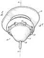
- FIG. 1is a view in perspective of the valve adapted for closing a body orifice (not shown) wherein the valve is shown in its open position.
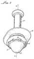
- FIG. 2is a view in cross section of the valve as would be seen along line 2 — 2 of FIG. 1 .
- FIG. 3is a view in cross section of the valve similar to that of FIG. 2 but wherein therein the valve is shown flipped over center with respect to the hinge in its valve closed position.
- FIG. 4is a view in perspective of an alternate valve adapted for closing a body orifice (not shown) wherein the alternate valve is shown in its open position.
- FIG. 5is a view in cross section of the alternate valve as would be seen along line 5 — 5 of FIG. 4 .
- FIG. 6is a view in cross section of the alternate valve similar to that of FIG. 5 but wherein therein the alternate valve is shown flipped over center with respect to the hinge in its alternate valve closed position.
- FIG. 7is a view in perspective of an alternative valve adapted for closing a body orifice (not shown) wherein the alternate valve is shown in its open position.
- FIG. 8is a view in cross section of the alternative valve as would be seen along line 8 — 8 of FIG. 7 .
- FIG. 9is a view in cross section of the alternative valve similar to that of FIG. 8 but wherein therein the alternative valve is shown flipped over center with respect to the hinge in its alternative valve closed position.
- a valve 10 adapted for closing a body orificehas a bulbous tube 11 formed of a flexible material as its main structure and shape.
- the bulbous tube 11is preferably molded as one integral component but can be cast integrally or assembled from separately made parts, see FIGS. 1, 2 , 3 , 4 , 5 , 6 , and 7 .
- the bulbous tube 11has an inlet 12 that is fixed across the body orifice and an outlet 13 positioned away from the body orifice for controlling incontinence.
- the outlet 13is open when the valve 10 is unseated as will be understood upon a complete reading of this disclosure.
- the body orificemay be the female meatus and its passageway, the urethra, for urine (not shown in the FIGS.).
- a flange 14 located around the inlet 12 of the bulbous tube 11is used in the preferred embodiment to attach to the body with a medical grade adhesive such as a moisture effusing acrylic. Skilled artisans would know the proper adhesive to accommodate bodily fluids without disconnection or leakage and to minimize irritation.
- the flange 14most preferably has a generally flat ring shaped configuration to circumscribe the inlet 12 and to interface about the body orifice see FIGS. 1, 2 , 3 , 4 , 5 , 6 and 7 .
- a passage 15is formed within and passes through the bulbous tube 11 for extending from the inlet 12 along an axis A—A therethrough between the inlet 12 and outlet 13 .
- a wall 16in FIGS. 3, 5 , 6 and 8 , of the bulbous tube 11 is preferably integral therewith.
- the wall 16is in the preferred embodiment located between the inlet 12 and the outlet 13 . Consistent with the configuration of the bulbous tube 11 the wall 16 is about 0.5 mm and has a barrel shape 17 as shown in FIGS. 2, 5 and 8 .
- the barrel shape 17tapers toward the inlet 12 and the outlet 13 so the bulbous tube 11 is wider therebetween.
- the passage 15 through the bulbous tube 11is wider between the inlet 12 and the outlet 13 .
- the wall 16is between an inside 18 and an outside 19 as seen the view in cross section of FIGS. 3, 5 , 6 and 8 .
- the preferred wall 16is about 0.5 mm thick but the particular thickness is more a function of the durometer of the flexible polymer.
- the preferred polymeris C-Flex TPE Thermoplastic made by Consolidated Polymer Technologies, Inc. of Largo, Fla.
- C-Flex polymerhas an 18 shore A durometer and the preferred wall 16 thickness of 0.5 mm; the valve 10 seating force is 15 grams and the over center force is about 50 grams. Of course the forces are a balance between the force to hold the valve 10 closed and the adhesive connection about the body orifice.
- a hinge 20is an integral part of the wall 16 and runs about the bulbous tube 11 .
- the hinge 20is preferred to be located axially in the wall 16 substantially wherein the barrel shape 17 wall 16 defines the passage 15 therethrough; that is at the widest part of the bulbous tube 11 .
- the hinge 20acts as an area of preferential bending at the barrel shape 17 so the bulbous tube 11 is either normally barrel shaped 17 , in FIGS. 1, 2 , 4 , 5 , 7 and 8 , or flipped with the outlet 13 thereof folded about the hinge 20 and into the passage 15 in FIGS. 3 and 6.
- the force to flip the hinge 20has been measured in the range of about 10 to 100 grams but preferably 15 grams as explained. While the preferred hinge 20 is, that is either open or closed, the hinge 20 can also be arranged to be normally closed such that to keep it open the outlet 13 must be pulled away from a seat 21 by the user or the pressure of urination force from the bladder down the urethra may be applied for holding the outlet 13 away from the seat 21 .
- This form of hinge 20 operationcan be considered monostable but the valve 10 would look the same since the bias of the hinge 20 is not really apparent in illustrations. Consequently, as used herein the term, “bistable” includes normally open or closed valves 10 or alternatively normally closed valves 10 as explained.
- the seat 21is positioned within the bulbous tube 11 on the inside 18 of the wall 16 .
- the seat 21is be disposed within the passage 15 to engage the outlet 13 when the bulbous tube 11 is flipped into the passage 15 after bending the hinge 20 acutely.
- the outlet 13is then moved along the axis A—A toward the inlet 12 so the outlet 13 is held against the seat 21 to seal the inlet 12 and close the passage 15 .
- the seat 21is axially between the inlet 12 and the wide part of the barrel shape 17 of the bulbous tube 11 , see FIGS. 2, 5 and 8 .
- One or more holes 22are preferably dispose through the wall 22 .
- Each hole 22might be located in a plane substantially normal to the axis and away from the inlet 12 and axially beyond the hinge 20 .
- the outlet 13may surround a bottom 23 of the bulbous tube 11 so that when flipped bulbous tube 11 moves the bottom 23 axially into the passage 15 .
- the bottom 23 in FIGS. 1, 2 and 3locates the one or more holes 22 dispose through the wall 16 in contact with the seat 21 and positions the bottom 23 to close the inlet 12 ; this is best shown in the view in cross section of FIGS. 1, 2 , 4 , 5 , 7 and 8 .
- the outlet 13 in another alternate embodiment of FIGS. 4, 5 and 6includes a plug 24 supported from the wall 16 and within the outlet 13 by a web 25 so that when the flipped bulbous tube 11 moves the plug 24 axially through the passage 15 the plug 24 seats; this is best shown in the view in cross section of FIGS. 5 and 6.
- the plug 24contacts the seat 21 and closes the inlet 12 .
- the wall 16 about the inlet 12may in this version include a pipe 26 depending at the wall 16 inside 18 thereabout.
- the pipe 26 in FIGS. 5 and 6is thus in the passage 15 so the seat 21 is most preferably on the pipe 26 away from the inlet 12 . Consequently, the seat 21 and the pipe 26 can be adapted to engage remotely, or axially along the passage 15 , closing the inlet 12 .
- the inlet 12might include a duct 27 positioned thereabout to surround the inlet 12 and extend passage 15 away from the outlet 13 .
- the duct 27 , the flange 14 and the bulbous tube 11are thus in that arrangement adapted for fluid communication with the body orifice.
- the duct 27extends into the urethra (not shown) may have a gel 28 in FIG. 8 about it to protect the patient's body, help the fit therein and ease insertion.
- the bulbous tube 11is preferred to be circular in cross section as shown in all the Figures and substantially symmetrical about the axis A—A as shown in the preferred valves 10 .
- the preferred inlet 12 and outlet 13are substantially normal to the axis A—A but need not be symmetric or circular.
- the bulbous tube 11is formed of a flexible polymer by molding.
- the outlet 13may have a grip 29 in FIGS. 2, 3 , 4 , 5 and 6 projecting therefrom for use in pulling the outlet 13 to flip the hinge 20 and open the passage 15 between the inlet 12 and outlet 13 .
- a method of making valve 10 adapted for closing an orificeincludes steps. Forming bulbous tube 11 of a flexible material is a step. The step of having on the bulbous tube 11 inlet 12 fixed for placement across the orifice and outlet 13 positioned away from the orifice is a step. The step of locating flange 14 with a generally flat ring shape around the inlet 12 of the bulbous tube 11 to interface about the orifice is performed in this method. Extending passage 15 within and through the bulbous tube 11 from the inlet 12 along axis A—A therethrough is a step. Having barrel shaped 17 wall 16 on the bulbous tube 11 with the wall 16 tapering toward the inlet 12 and the outlet 13 and thus wider therebetween is a step. Locating the wall 16 between inside 18 and outside 19 is a step.
- Locating hinge 20 about the bulbous tube 11 and in the wall 16 as an area of preferential bending so the bulbous tube 11 is either normally barrel shaped 17 or flipped with the outlet 13 folded about the hinge 20 into the passage 15is a step.
- Preferentially bending the hinge 20is a step.
- the step of locating seat 21 on the inside 18 of the wall 16 to engage the outlet 13 when the bulbous tube 11 is flipped into the passage 15 by bending the hinge 20 acutely so the outlet 13 is moved along the axis A—A toward the inlet 12 and held against the seat 21is in the method.
- a method of using the valve 10has the bulbous tube 11 formed of a flexible material.
- the bulbous tube 11has the inlet 12 fixed across the orifice and outlet 13 opposite thereto.
- the bulbous tube 11has barrel shape 17 tapering toward the inlet 12 and the outlet 13 so the hinge 20 is about the bulbous tube 11 .
- the hinge 20is an area of preferential bending.
- the bulbous tube 11is either normally barrel shaped 17 or flipped with the outlet 13 folded about the hinge 20 so seat 21 within the bulbous tube 11 seals the outlet 13 .
- the method of usingwith the step of flipping the bulbous tube 11 by bending the hinge 20 acutely moves the outlet 13 toward the inlet 12 for holding against the seat 21 .
- valve 10sought to be protected by the claims that follow has the outlet 13 that seats or is unrestricted excepted when seated.
Landscapes
- Health & Medical Sciences (AREA)
- Urology & Nephrology (AREA)
- Cardiology (AREA)
- Oral & Maxillofacial Surgery (AREA)
- Transplantation (AREA)
- Engineering & Computer Science (AREA)
- Biomedical Technology (AREA)
- Heart & Thoracic Surgery (AREA)
- Vascular Medicine (AREA)
- Life Sciences & Earth Sciences (AREA)
- Animal Behavior & Ethology (AREA)
- General Health & Medical Sciences (AREA)
- Public Health (AREA)
- Veterinary Medicine (AREA)
- Prostheses (AREA)
- Check Valves (AREA)
Abstract
Description
Claims (17)
Priority Applications (1)
| Application Number | Priority Date | Filing Date | Title |
|---|---|---|---|
| US09/767,208US6443886B2 (en) | 1998-03-04 | 2001-01-22 | Valve and methods for urinary control |
Applications Claiming Priority (2)
| Application Number | Priority Date | Filing Date | Title |
|---|---|---|---|
| US09/034,250US6200261B1 (en) | 1998-03-04 | 1998-03-04 | Valve and methods for urinary control |
| US09/767,208US6443886B2 (en) | 1998-03-04 | 2001-01-22 | Valve and methods for urinary control |
Related Parent Applications (1)
| Application Number | Title | Priority Date | Filing Date |
|---|---|---|---|
| US09/034,250ContinuationUS6200261B1 (en) | 1998-03-04 | 1998-03-04 | Valve and methods for urinary control |
Publications (2)
| Publication Number | Publication Date |
|---|---|
| US20010002428A1 US20010002428A1 (en) | 2001-05-31 |
| US6443886B2true US6443886B2 (en) | 2002-09-03 |
Family
ID=21875233
Family Applications (2)
| Application Number | Title | Priority Date | Filing Date |
|---|---|---|---|
| US09/034,250Expired - LifetimeUS6200261B1 (en) | 1998-03-04 | 1998-03-04 | Valve and methods for urinary control |
| US09/767,208Expired - LifetimeUS6443886B2 (en) | 1998-03-04 | 2001-01-22 | Valve and methods for urinary control |
Family Applications Before (1)
| Application Number | Title | Priority Date | Filing Date |
|---|---|---|---|
| US09/034,250Expired - LifetimeUS6200261B1 (en) | 1998-03-04 | 1998-03-04 | Valve and methods for urinary control |
Country Status (7)
| Country | Link |
|---|---|
| US (2) | US6200261B1 (en) |
| EP (1) | EP1065991A1 (en) |
| JP (1) | JP2002505143A (en) |
| AU (1) | AU2978399A (en) |
| CA (1) | CA2321519A1 (en) |
| TW (1) | TW374726B (en) |
| WO (1) | WO1999044532A1 (en) |
Cited By (6)
| Publication number | Priority date | Publication date | Assignee | Title |
|---|---|---|---|---|
| US6936052B2 (en) | 2001-03-09 | 2005-08-30 | Boston Scientific Scimed, Inc. | System for implanting an implant and method thereof |
| US7025772B2 (en) | 2001-03-09 | 2006-04-11 | Scimed Life Systems, Inc. | System for implanting an implant and method thereof |
| US20060195009A1 (en)* | 2004-12-06 | 2006-08-31 | Sam Drager | Apparatus and method for correcting urinary incontinence |
| US7361138B2 (en) | 2003-07-31 | 2008-04-22 | Scimed Life Systems, Inc. | Bioabsorbable casing for surgical sling assembly |
| US7402133B2 (en) | 2002-12-17 | 2008-07-22 | Boston Scientific Scimed, Inc. | Spacer for sling delivery system |
| US8033983B2 (en) | 2001-03-09 | 2011-10-11 | Boston Scientific Scimed, Inc. | Medical implant |
Families Citing this family (15)
| Publication number | Priority date | Publication date | Assignee | Title |
|---|---|---|---|---|
| US6056687A (en) | 1997-12-04 | 2000-05-02 | American Medical Systems, Inc. | Device for alleviating urinary incontinence |
| US6200261B1 (en) | 1998-03-04 | 2001-03-13 | American Medical Systems, Inc. | Valve and methods for urinary control |
| US6491713B1 (en) | 1999-04-05 | 2002-12-10 | Ams Research Corporation | Method and apparatus for placement of a bladder output control device |
| US6391142B1 (en)* | 2000-01-07 | 2002-05-21 | Steven T. Deininger | Method of bonding substrates |
| FR2806706B1 (en)* | 2000-03-27 | 2002-07-26 | Oreal | AIR INTAKE ELEMENT, CAPSULE PROVIDED WITH SUCH AN ELEMENT, CONTAINER PROVIDED WITH SUCH AN ELEMENT OR SUCH A CAPSULE, AND ASSEMBLY COMPRISING SUCH A CONTAINER |
| US6863261B2 (en)* | 2002-03-12 | 2005-03-08 | Baxter International Inc. | Valve stop |
| US20040242956A1 (en)* | 2002-07-29 | 2004-12-02 | Scorvo Sean K. | System for controlling fluid in a body |
| US6893222B2 (en)* | 2003-02-10 | 2005-05-17 | United Technologies Corporation | Turbine balancing |
| BRPI0408512A (en)* | 2003-03-17 | 2006-03-07 | Global Valve Technology Pty Lt | sports ball valve |
| US20060195006A1 (en)* | 2005-02-28 | 2006-08-31 | Daurelle Bernard Adrien S | Intraurethral incontinence device and methods |
| US9364306B2 (en)* | 2011-09-12 | 2016-06-14 | Boston Scientific Scimed, Inc. | Implantable medical device and method of placement of the implantable medical device |
| EP3082665B1 (en)* | 2013-12-18 | 2018-03-07 | Coloplast A/S | An adaptable ostomy base plate |
| DE202014003500U1 (en)* | 2014-04-29 | 2015-07-30 | Svd-Verpackungen Gmbh | Reclosable valve device and packaging with valve device |
| WO2016005824A1 (en)* | 2014-07-09 | 2016-01-14 | Ovitigalage Saliya Ovitigala | Intra-urethral device for the treatment of urinary incontinence of females |
| WO2016146135A1 (en) | 2015-03-16 | 2016-09-22 | Coloplast A/S | Ostomy device |
Citations (39)
| Publication number | Priority date | Publication date | Assignee | Title |
|---|---|---|---|---|
| DE520759C (en) | 1931-03-17 | Arthur Fritz Koppel | Shut-off valve | |
| US2510766A (en) | 1947-12-06 | 1950-06-06 | Carl F Surface | Colostomy control device |
| US3547401A (en) | 1968-06-07 | 1970-12-15 | Abbott Lab | Foldable bellows valve |
| US3758073A (en)* | 1971-10-26 | 1973-09-11 | R Schulte | Valve for physiological drainage actuable by lateral compression |
| US3841304A (en) | 1972-10-16 | 1974-10-15 | A Jones | Inflatable leakage inhibitor |
| US4056116A (en)* | 1976-09-08 | 1977-11-01 | Baxter Travenol Laboratories, Inc. | Valve for interconnecting sterile containers and the like |
| US4198029A (en)* | 1976-10-08 | 1980-04-15 | Textron, Inc. | Throttling control valve |
| US4210132A (en) | 1978-07-26 | 1980-07-01 | The Kendall Company | Artificial sphincter |
| US4344434A (en) | 1981-06-01 | 1982-08-17 | Santa Barbara Medical Foundation Clinic | Ileostomy appliance and method for implanting the same |
| US4471807A (en)* | 1981-05-12 | 1984-09-18 | Waddington & Duval Limited | Press taps |
| US4552128A (en) | 1983-12-29 | 1985-11-12 | Haber Terry M | Elastomechanical sphincter |
| US4587954A (en) | 1983-12-29 | 1986-05-13 | Habley Medical Technology Corporation | Elastomeric prosthetic sphincter |
| US4631062A (en) | 1984-09-27 | 1986-12-23 | Kimberly-Clark Corporation | Labial sanitary pad |
| US4690677A (en) | 1985-09-25 | 1987-09-01 | Daltex Medical Sciences, Inc. | Urine collection system for females |
| US4691836A (en) | 1983-01-06 | 1987-09-08 | Victor Wassilieff | Apertured closure device with depressible disc portion |
| US4822333A (en) | 1986-03-11 | 1989-04-18 | Lavarenne Vincent A | Urethral endoprosthesis |
| US4968294A (en) | 1989-02-09 | 1990-11-06 | Salama Fouad A | Urinary control valve and method of using same |
| US5074855A (en) | 1991-01-10 | 1991-12-24 | Advanced Surgical Intervention, Inc. | Urinary incontinence pad |
| US5082006A (en) | 1987-09-15 | 1992-01-21 | Linda Jonasson | Device for preventing involuntary micturition |
| WO1992006731A1 (en) | 1990-10-22 | 1992-04-30 | Salama Fouad A | Urinary control with inflatable seal |
| US5114398A (en) | 1990-02-27 | 1992-05-19 | Medical Engineering Corporation | Female incontinence control device with mechanically operable valve |
| WO1992011826A1 (en) | 1990-12-31 | 1992-07-23 | Uromed Corporation | A method and a removable device which can be used for the self-administered treatment of urinary tract infections or other disorders and as a urethral plug |
| WO1992019192A1 (en) | 1991-04-25 | 1992-11-12 | Coloplast As | A device for preventing involuntary urination, preferable for females |
| EP0535778A1 (en) | 1991-09-30 | 1993-04-07 | Primed International Corp. | Urinary incontinence valve device |
| WO1993008765A1 (en) | 1991-10-28 | 1993-05-13 | Paul Bader | Incontinence valve |
| GB2267579A (en) | 1992-05-15 | 1993-12-08 | Sharp Kk | Optical device comprising facing lenticular or parallax screens of different pitch |
| WO1994026215A1 (en) | 1993-05-17 | 1994-11-24 | Uromed Corporation | Expandable urethral plug |
| WO1996026688A1 (en) | 1995-02-27 | 1996-09-06 | Iotek, Inc. | Everting incontinence plug |
| WO1996039096A1 (en) | 1995-06-05 | 1996-12-12 | Iotek, Inc. | Rolling incontinence plug |
| WO1996039989A1 (en) | 1995-06-07 | 1996-12-19 | Nebl, Inc. | Female urinary incontinence device |
| WO1996039991A1 (en) | 1995-06-07 | 1996-12-19 | Nebl, Inc. | Urethral cap |
| WO1997006758A1 (en) | 1995-08-16 | 1997-02-27 | Hk Medical Technologies Incorporated | Intraurethral bladder control device with retainer apparatus |
| WO1997017909A1 (en) | 1995-11-14 | 1997-05-22 | Uromed Corporation | Method and device for controlling urinary incontinence |
| EP0780105A2 (en) | 1995-12-19 | 1997-06-25 | José Manuel Doladé Guardia | Device for women suffering from incontinence |
| WO1997025947A1 (en) | 1996-01-19 | 1997-07-24 | Uromed Corporation | Device and method to control urinary incontinence |
| WO1998019640A1 (en) | 1996-11-08 | 1998-05-14 | Pri-Med International Corp. | Urinary incontinence valve with distal and proximal anchoring means |
| WO1998025555A1 (en) | 1996-12-12 | 1998-06-18 | Dann Jeffrey A | Female incontinence device |
| US5813973A (en)* | 1996-05-30 | 1998-09-29 | Gloth; David | Device and method for alleviating female urinary incontinence |
| US6200261B1 (en) | 1998-03-04 | 2001-03-13 | American Medical Systems, Inc. | Valve and methods for urinary control |
Family Cites Families (6)
| Publication number | Priority date | Publication date | Assignee | Title |
|---|---|---|---|---|
| US5336208A (en) | 1991-01-10 | 1994-08-09 | Advanced Surgical Intervention, Inc. | Urinary incontinence pad |
| US5352182A (en) | 1992-05-27 | 1994-10-04 | Kalb Irvin M | Product and method to treat female incontinence |
| GB2267549A (en)* | 1992-06-06 | 1993-12-08 | Elley John Andrew | Disposable teat valve |
| US5640976A (en) | 1995-06-06 | 1997-06-24 | Iotek, Inc. | Incontinence plug anchor |
| US5813974A (en) | 1995-12-19 | 1998-09-29 | Dolade Guardia; Jose Manuel | Device for women suffering from incontinence |
| US5722931A (en) | 1996-03-05 | 1998-03-03 | Urohealth Systems, Inc. | Female incontinence device |
- 1998
- 1998-03-04USUS09/034,250patent/US6200261B1/ennot_activeExpired - Lifetime
- 1999
- 1999-03-03EPEP99911048Apatent/EP1065991A1/ennot_activeWithdrawn
- 1999-03-03JPJP2000534140Apatent/JP2002505143A/enactivePending
- 1999-03-03CACA002321519Apatent/CA2321519A1/ennot_activeAbandoned
- 1999-03-03WOPCT/US1999/004576patent/WO1999044532A1/ennot_activeApplication Discontinuation
- 1999-03-03AUAU29783/99Apatent/AU2978399A/ennot_activeAbandoned
- 1999-03-04TWTW088103288Apatent/TW374726B/enactive
- 2001
- 2001-01-22USUS09/767,208patent/US6443886B2/ennot_activeExpired - Lifetime
Patent Citations (40)
| Publication number | Priority date | Publication date | Assignee | Title |
|---|---|---|---|---|
| DE520759C (en) | 1931-03-17 | Arthur Fritz Koppel | Shut-off valve | |
| US2510766A (en) | 1947-12-06 | 1950-06-06 | Carl F Surface | Colostomy control device |
| US3547401A (en) | 1968-06-07 | 1970-12-15 | Abbott Lab | Foldable bellows valve |
| US3758073A (en)* | 1971-10-26 | 1973-09-11 | R Schulte | Valve for physiological drainage actuable by lateral compression |
| US3841304A (en) | 1972-10-16 | 1974-10-15 | A Jones | Inflatable leakage inhibitor |
| US4056116A (en)* | 1976-09-08 | 1977-11-01 | Baxter Travenol Laboratories, Inc. | Valve for interconnecting sterile containers and the like |
| US4198029A (en)* | 1976-10-08 | 1980-04-15 | Textron, Inc. | Throttling control valve |
| US4210132A (en) | 1978-07-26 | 1980-07-01 | The Kendall Company | Artificial sphincter |
| US4471807A (en)* | 1981-05-12 | 1984-09-18 | Waddington & Duval Limited | Press taps |
| US4344434A (en) | 1981-06-01 | 1982-08-17 | Santa Barbara Medical Foundation Clinic | Ileostomy appliance and method for implanting the same |
| US4691836A (en) | 1983-01-06 | 1987-09-08 | Victor Wassilieff | Apertured closure device with depressible disc portion |
| US4552128A (en) | 1983-12-29 | 1985-11-12 | Haber Terry M | Elastomechanical sphincter |
| US4587954A (en) | 1983-12-29 | 1986-05-13 | Habley Medical Technology Corporation | Elastomeric prosthetic sphincter |
| US4631062A (en) | 1984-09-27 | 1986-12-23 | Kimberly-Clark Corporation | Labial sanitary pad |
| US4690677A (en) | 1985-09-25 | 1987-09-01 | Daltex Medical Sciences, Inc. | Urine collection system for females |
| US4822333A (en) | 1986-03-11 | 1989-04-18 | Lavarenne Vincent A | Urethral endoprosthesis |
| US5082006A (en) | 1987-09-15 | 1992-01-21 | Linda Jonasson | Device for preventing involuntary micturition |
| US4968294A (en) | 1989-02-09 | 1990-11-06 | Salama Fouad A | Urinary control valve and method of using same |
| US5114398A (en) | 1990-02-27 | 1992-05-19 | Medical Engineering Corporation | Female incontinence control device with mechanically operable valve |
| WO1992006731A1 (en) | 1990-10-22 | 1992-04-30 | Salama Fouad A | Urinary control with inflatable seal |
| WO1992011826A1 (en) | 1990-12-31 | 1992-07-23 | Uromed Corporation | A method and a removable device which can be used for the self-administered treatment of urinary tract infections or other disorders and as a urethral plug |
| US5074855A (en) | 1991-01-10 | 1991-12-24 | Advanced Surgical Intervention, Inc. | Urinary incontinence pad |
| WO1992019192A1 (en) | 1991-04-25 | 1992-11-12 | Coloplast As | A device for preventing involuntary urination, preferable for females |
| EP0535778A1 (en) | 1991-09-30 | 1993-04-07 | Primed International Corp. | Urinary incontinence valve device |
| WO1993008765A1 (en) | 1991-10-28 | 1993-05-13 | Paul Bader | Incontinence valve |
| GB2267579A (en) | 1992-05-15 | 1993-12-08 | Sharp Kk | Optical device comprising facing lenticular or parallax screens of different pitch |
| WO1994026215A1 (en) | 1993-05-17 | 1994-11-24 | Uromed Corporation | Expandable urethral plug |
| WO1996026688A1 (en) | 1995-02-27 | 1996-09-06 | Iotek, Inc. | Everting incontinence plug |
| WO1996039096A1 (en) | 1995-06-05 | 1996-12-12 | Iotek, Inc. | Rolling incontinence plug |
| WO1996039989A1 (en) | 1995-06-07 | 1996-12-19 | Nebl, Inc. | Female urinary incontinence device |
| WO1996039991A1 (en) | 1995-06-07 | 1996-12-19 | Nebl, Inc. | Urethral cap |
| WO1996039990A1 (en) | 1995-06-07 | 1996-12-19 | Insight Medical Corporation | Urethral cap |
| WO1997006758A1 (en) | 1995-08-16 | 1997-02-27 | Hk Medical Technologies Incorporated | Intraurethral bladder control device with retainer apparatus |
| WO1997017909A1 (en) | 1995-11-14 | 1997-05-22 | Uromed Corporation | Method and device for controlling urinary incontinence |
| EP0780105A2 (en) | 1995-12-19 | 1997-06-25 | José Manuel Doladé Guardia | Device for women suffering from incontinence |
| WO1997025947A1 (en) | 1996-01-19 | 1997-07-24 | Uromed Corporation | Device and method to control urinary incontinence |
| US5813973A (en)* | 1996-05-30 | 1998-09-29 | Gloth; David | Device and method for alleviating female urinary incontinence |
| WO1998019640A1 (en) | 1996-11-08 | 1998-05-14 | Pri-Med International Corp. | Urinary incontinence valve with distal and proximal anchoring means |
| WO1998025555A1 (en) | 1996-12-12 | 1998-06-18 | Dann Jeffrey A | Female incontinence device |
| US6200261B1 (en) | 1998-03-04 | 2001-03-13 | American Medical Systems, Inc. | Valve and methods for urinary control |
Cited By (13)
| Publication number | Priority date | Publication date | Assignee | Title |
|---|---|---|---|---|
| US8033983B2 (en) | 2001-03-09 | 2011-10-11 | Boston Scientific Scimed, Inc. | Medical implant |
| US6991597B2 (en) | 2001-03-09 | 2006-01-31 | Boston Scientific Scimed, Inc. | System for implanting an implant and method thereof |
| US7025772B2 (en) | 2001-03-09 | 2006-04-11 | Scimed Life Systems, Inc. | System for implanting an implant and method thereof |
| US8617048B2 (en) | 2001-03-09 | 2013-12-31 | Boston Scientific Scimed, Inc. | System for implanting an implant and method thereof |
| US7235043B2 (en) | 2001-03-09 | 2007-06-26 | Boston Scientific Scimed Inc. | System for implanting an implant and method thereof |
| US8162816B2 (en) | 2001-03-09 | 2012-04-24 | Boston Scientific Scimed, Inc. | System for implanting an implant and method thereof |
| US6936052B2 (en) | 2001-03-09 | 2005-08-30 | Boston Scientific Scimed, Inc. | System for implanting an implant and method thereof |
| US7402133B2 (en) | 2002-12-17 | 2008-07-22 | Boston Scientific Scimed, Inc. | Spacer for sling delivery system |
| US8632453B2 (en) | 2002-12-17 | 2014-01-21 | Boston Scientific Scimed, Inc. | Spacer for sling delivery system |
| US7824326B2 (en) | 2003-07-31 | 2010-11-02 | Boston Scientific Scimed, Inc. | Bioabsorbable casing for surgical sling assembly |
| US7361138B2 (en) | 2003-07-31 | 2008-04-22 | Scimed Life Systems, Inc. | Bioabsorbable casing for surgical sling assembly |
| US7666133B2 (en) | 2004-12-06 | 2010-02-23 | Sam Drager | Apparatus and method for correcting urinary incontinence |
| US20060195009A1 (en)* | 2004-12-06 | 2006-08-31 | Sam Drager | Apparatus and method for correcting urinary incontinence |
Also Published As
| Publication number | Publication date |
|---|---|
| JP2002505143A (en) | 2002-02-19 |
| US6200261B1 (en) | 2001-03-13 |
| EP1065991A1 (en) | 2001-01-10 |
| TW374726B (en) | 1999-11-21 |
| WO1999044532A1 (en) | 1999-09-10 |
| CA2321519A1 (en) | 1999-09-10 |
| AU2978399A (en) | 1999-09-20 |
| US20010002428A1 (en) | 2001-05-31 |
Similar Documents
| Publication | Publication Date | Title |
|---|---|---|
| US6443886B2 (en) | Valve and methods for urinary control | |
| US7037303B2 (en) | Urinary flow control valve | |
| AU634321B2 (en) | Female incontinence control device with magnetically operable valve and method | |
| US4968294A (en) | Urinary control valve and method of using same | |
| US5234409A (en) | Female incontinence control device and method | |
| US5041092A (en) | Urethral indwelling catheter with magnetically controlled drainage valve and method | |
| US5724994A (en) | Fluidly expandable urethral plug assembly which receives fluid from an external source and method for controlling urinary incontinence | |
| EP0407218B1 (en) | Female incontinence control device | |
| JPH03109065A (en) | Built-in type urethrocathetel with incontinence control device | |
| JPH11511989A (en) | Intraurethral bladder control device having a retainer device | |
| US20220346925A1 (en) | Male urinary incontinence prevention device | |
| US6056687A (en) | Device for alleviating urinary incontinence | |
| WO2001097743A3 (en) | Balloon occlusion device having a proximal valve | |
| EP0265207A1 (en) | Trans-urethral incontinence device | |
| US4721095A (en) | Device for controlling the flow of a fluid and a prosthetic organ equipped with this device | |
| JPH0399675A (en) | Internal urethral catheter | |
| US7306586B2 (en) | Continuous drainage adaptor | |
| US6171230B1 (en) | Female incontinence catheter | |
| AU2003210478B2 (en) | Urinary flow control valve | |
| MXPA00008598A (en) | Valve and methods for urinary control | |
| JPH1115370A (en) | Simulator for training catheter insertion | |
| MXPA98008325A (en) | Device to relieve urine incontinence |
Legal Events
| Date | Code | Title | Description |
|---|---|---|---|
| STCF | Information on status: patent grant | Free format text:PATENTED CASE | |
| AS | Assignment | Owner name:AMS RESEARCH CORPORATION, MINNESOTA Free format text:ASSIGNMENT OF ASSIGNORS INTEREST;ASSIGNOR:AMERICAN MEDICAL SYSTEMS INC.;REEL/FRAME:013258/0477 Effective date:20021122 | |
| AS | Assignment | Owner name:BANK OF AMERICA, N.A., AS AGENT, NORTH CAROLINA Free format text:NOTICE OF GRANT OF SECURITY INTEREST;ASSIGNOR:AMS RESEARCH CORPORATION;REEL/FRAME:014186/0264 Effective date:20000417 | |
| FPAY | Fee payment | Year of fee payment:4 | |
| AS | Assignment | Owner name:AMS RESEARCH CORPORATION, MINNESOTA Free format text:RELEASE BY SECURED PARTY;ASSIGNOR:BANK OF AMERICA, N.A., AS AGENT;REEL/FRAME:017846/0729 Effective date:20060628 | |
| AS | Assignment | Owner name:AMS RESEARCH CORPORATION, MINNESOTA Free format text:RELEASE BY SECURED PARTY;ASSIGNOR:BANK OF AMERICA, N.A., AS AGENT;REEL/FRAME:017957/0522 Effective date:20060717 | |
| FPAY | Fee payment | Year of fee payment:8 | |
| AS | Assignment | Owner name:MORGAN STANLEY SENIOR FUNDING, INC., AS ADMINISTRA Free format text:SECURITY AGREEMENT;ASSIGNOR:AMS RESEARCH CORPORATION;REEL/FRAME:026632/0535 Effective date:20110617 | |
| FPAY | Fee payment | Year of fee payment:12 | |
| AS | Assignment | Owner name:AMS RESEARCH CORPORATION, MINNESOTA Free format text:RELEASE OF PATENT SECURITY INTEREST;ASSIGNOR:MORGAN STANLEY SENIOR FUNDING, INC., AS ADMINISTRATIVE AGENT;REEL/FRAME:032380/0053 Effective date:20140228 | |
| AS | Assignment | Owner name:DEUTSCHE BANK AG NEW YORK BRANCH, AS COLLATERAL AGENT, NEW YORK Free format text:GRANT OF SECURITY INTEREST IN PATENTS;ASSIGNORS:ENDO PHARMACEUTICALS SOLUTIONS, INC.;ENDO PHARMACEUTICALS, INC.;AMS RESEARCH CORPORATION;AND OTHERS;REEL/FRAME:032491/0440 Effective date:20140228 Owner name:DEUTSCHE BANK AG NEW YORK BRANCH, AS COLLATERAL AG Free format text:GRANT OF SECURITY INTEREST IN PATENTS;ASSIGNORS:ENDO PHARMACEUTICALS SOLUTIONS, INC.;ENDO PHARMACEUTICALS, INC.;AMS RESEARCH CORPORATION;AND OTHERS;REEL/FRAME:032491/0440 Effective date:20140228 | |
| AS | Assignment | Owner name:LASERSCOPE, CALIFORNIA Free format text:RELEASE BY SECURED PARTY;ASSIGNOR:DEUTSCHE BANK AG NEW YORK BRANCH;REEL/FRAME:036285/0146 Effective date:20150803 Owner name:AMS RESEARCH, LLC, MINNESOTA Free format text:RELEASE BY SECURED PARTY;ASSIGNOR:DEUTSCHE BANK AG NEW YORK BRANCH;REEL/FRAME:036285/0146 Effective date:20150803 Owner name:AMERICAN MEDICAL SYSTEMS, LLC, MINNESOTA Free format text:RELEASE BY SECURED PARTY;ASSIGNOR:DEUTSCHE BANK AG NEW YORK BRANCH;REEL/FRAME:036285/0146 Effective date:20150803 | |
| AS | Assignment | Owner name:AMS RESEARCH, LLC, MINNESOTA Free format text:CHANGE OF NAME;ASSIGNOR:AMS RESEARCH CORPATION;REEL/FRAME:037300/0318 Effective date:20141217 | |
| AS | Assignment | Owner name:APHRODITE WOMEN'S HEALTH, LLC, MINNESOTA Free format text:ASSIGNMENT OF ASSIGNORS INTEREST;ASSIGNOR:AMS RESEARCH, LLC;REEL/FRAME:037473/0260 Effective date:20150227 Owner name:ASTORA WOMEN'S HEALTH, LLC, MINNESOTA Free format text:CHANGE OF NAME;ASSIGNOR:APHRODITE WOMEN'S HEALTH, LLC;REEL/FRAME:037473/0354 Effective date:20150929 | |
| AS | Assignment | Owner name:AMS RESEARCH, LLC, MINNESOTA Free format text:CORRECTIVE ASSIGNMENT TO CORRECT THE ASSIGNOR NAME PREVIOUSLY RECORDED AT REEL: 037300 FRAME: 0318. ASSIGNOR(S) HEREBY CONFIRMS THE CHANGE OF NAME;ASSIGNOR:AMS RESEARCH CORPORATION;REEL/FRAME:039919/0017 Effective date:20141217 | |
| AS | Assignment | Owner name:WILMINGTON TRUST, NATIONAL ASSOCIATION, AS COLLATERAL TRUSTEE, DELAWARE Free format text:SECURITY INTEREST;ASSIGNOR:ASTORA WOMEN'S HEALTH, LLC;REEL/FRAME:042743/0278 Effective date:20170427 Owner name:WILMINGTON TRUST, NATIONAL ASSOCIATION, AS COLLATE Free format text:SECURITY INTEREST;ASSIGNOR:ASTORA WOMEN'S HEALTH, LLC;REEL/FRAME:042743/0278 Effective date:20170427 | |
| AS | Assignment | Owner name:BOSTON SCIENTIFIC CORPORATION, MASSACHUSETTS Free format text:ASSIGNMENT OF ASSIGNORS INTEREST;ASSIGNORS:ASTORA WOMEN'S HEALTH, LLC;ENDO HEALTH SOLUTIONS INC.;ASTORA WOMEN'S HEALTH HOLDINGS, LLC;REEL/FRAME:043778/0302 Effective date:20161222 Owner name:BOSTON SCIENTIFIC SCIMED, INC., MINNESOTA Free format text:ASSIGNMENT OF ASSIGNORS INTEREST;ASSIGNOR:BOSTON SCIENTIFIC CORPORATION;REEL/FRAME:043780/0316 Effective date:20161222 | |
| AS | Assignment | Owner name:VINTAGE PHARMACEUTICALS, LLC, NEW YORK Free format text:RELEASE BY SECURED PARTY;ASSIGNOR:WILMINGTON TRUST, NATIONAL ASSOCIATION;REEL/FRAME:067240/0001 Effective date:20240423 Owner name:SLATE PHARMACEUTICALS, LLC, PENNSYLVANIA Free format text:RELEASE BY SECURED PARTY;ASSIGNOR:WILMINGTON TRUST, NATIONAL ASSOCIATION;REEL/FRAME:067240/0001 Effective date:20240423 Owner name:QUARTZ SPECIALTY PHARMACEUTICALS, LLC, NEW YORK Free format text:RELEASE BY SECURED PARTY;ASSIGNOR:WILMINGTON TRUST, NATIONAL ASSOCIATION;REEL/FRAME:067240/0001 Effective date:20240423 Owner name:PAR STERILE PRODUCTS, LLC (FORMERLY KNOWN AS JHP PHARMACEUTICALS, LLC), NEW YORK Free format text:RELEASE BY SECURED PARTY;ASSIGNOR:WILMINGTON TRUST, NATIONAL ASSOCIATION;REEL/FRAME:067240/0001 Effective date:20240423 Owner name:PAR PHARMACEUTICAL, INC., NEW YORK Free format text:RELEASE BY SECURED PARTY;ASSIGNOR:WILMINGTON TRUST, NATIONAL ASSOCIATION;REEL/FRAME:067240/0001 Effective date:20240423 Owner name:GENERICS INTERNATIONAL (US), INC., NEW YORK Free format text:RELEASE BY SECURED PARTY;ASSIGNOR:WILMINGTON TRUST, NATIONAL ASSOCIATION;REEL/FRAME:067240/0001 Effective date:20240423 Owner name:GENERICS BIDCO I, LLC, NEW YORK Free format text:RELEASE BY SECURED PARTY;ASSIGNOR:WILMINGTON TRUST, NATIONAL ASSOCIATION;REEL/FRAME:067240/0001 Effective date:20240423 Owner name:ENDO PHARMACEUTICALS SOLUTIONS INC. (FORMERLY KNOWN AS INDEVUS PHARMACEUTICALS, INC.), PENNSYLVANIA Free format text:RELEASE BY SECURED PARTY;ASSIGNOR:WILMINGTON TRUST, NATIONAL ASSOCIATION;REEL/FRAME:067240/0001 Effective date:20240423 Owner name:ENDO PHARMACEUTICALS INC., PENNSYLVANIA Free format text:RELEASE BY SECURED PARTY;ASSIGNOR:WILMINGTON TRUST, NATIONAL ASSOCIATION;REEL/FRAME:067240/0001 Effective date:20240423 Owner name:ENDO GENERIC HOLDINGS, INC. (FORMERLY KNOWN AS PAR PHARMACEUTICALS COMPANIES, INC.), PENNSYLVANIA Free format text:RELEASE BY SECURED PARTY;ASSIGNOR:WILMINGTON TRUST, NATIONAL ASSOCIATION;REEL/FRAME:067240/0001 Effective date:20240423 Owner name:DAVA PHARMACEUTICALS, LLC, NEW YORK Free format text:RELEASE BY SECURED PARTY;ASSIGNOR:WILMINGTON TRUST, NATIONAL ASSOCIATION;REEL/FRAME:067240/0001 Effective date:20240423 Owner name:DAVA INTERNATIONAL, LLC, PENNSYLVANIA Free format text:RELEASE BY SECURED PARTY;ASSIGNOR:WILMINGTON TRUST, NATIONAL ASSOCIATION;REEL/FRAME:067240/0001 Effective date:20240423 Owner name:BIOSPECIFICS TECHNOLOGIES LLC, PENNSYLVANIA Free format text:RELEASE BY SECURED PARTY;ASSIGNOR:WILMINGTON TRUST, NATIONAL ASSOCIATION;REEL/FRAME:067240/0001 Effective date:20240423 Owner name:BIOSPECIFICS TECHNOLOGIES CORP., PENNSYLVANIA Free format text:RELEASE BY SECURED PARTY;ASSIGNOR:WILMINGTON TRUST, NATIONAL ASSOCIATION;REEL/FRAME:067240/0001 Effective date:20240423 Owner name:AUXILIUM US HOLDINGS, LLC, PENNSYLVANIA Free format text:RELEASE BY SECURED PARTY;ASSIGNOR:WILMINGTON TRUST, NATIONAL ASSOCIATION;REEL/FRAME:067240/0001 Effective date:20240423 Owner name:AUXILIUM PHARMACEUTICALS, LLC, PENNSYLVANIA Free format text:RELEASE BY SECURED PARTY;ASSIGNOR:WILMINGTON TRUST, NATIONAL ASSOCIATION;REEL/FRAME:067240/0001 Effective date:20240423 Owner name:ASTORA WOMEN'S HEALTH LLC, PENNSYLVANIA Free format text:RELEASE BY SECURED PARTY;ASSIGNOR:WILMINGTON TRUST, NATIONAL ASSOCIATION;REEL/FRAME:067240/0001 Effective date:20240423 Owner name:ASTORA WOMEN'S HEALTH HOLDINGS, LLC, MINNESOTA Free format text:RELEASE BY SECURED PARTY;ASSIGNOR:WILMINGTON TRUST, NATIONAL ASSOCIATION;REEL/FRAME:067240/0001 Effective date:20240423 Owner name:ACTIENT PHARMACEUTICALS LLC, PENNSYLVANIA Free format text:RELEASE BY SECURED PARTY;ASSIGNOR:WILMINGTON TRUST, NATIONAL ASSOCIATION;REEL/FRAME:067240/0001 Effective date:20240423 |