US6443052B1 - Household electric cooking appliance and apparatus for assembling and storing the appliance - Google Patents
Household electric cooking appliance and apparatus for assembling and storing the applianceDownload PDFInfo
- Publication number
- US6443052B1 US6443052B1US09/255,419US25541999AUS6443052B1US 6443052 B1US6443052 B1US 6443052B1US 25541999 AUS25541999 AUS 25541999AUS 6443052 B1US6443052 B1US 6443052B1
- Authority
- US
- United States
- Prior art keywords
- griddle
- skillet
- appliance
- plate
- lid
- Prior art date
- Legal status (The legal status is an assumption and is not a legal conclusion. Google has not performed a legal analysis and makes no representation as to the accuracy of the status listed.)
- Expired - Lifetime, expires
Links
Images


Classifications
- A—HUMAN NECESSITIES
- A47—FURNITURE; DOMESTIC ARTICLES OR APPLIANCES; COFFEE MILLS; SPICE MILLS; SUCTION CLEANERS IN GENERAL
- A47J—KITCHEN EQUIPMENT; COFFEE MILLS; SPICE MILLS; APPARATUS FOR MAKING BEVERAGES
- A47J27/00—Cooking-vessels
- A47J27/004—Cooking-vessels with integral electrical heating means
- A—HUMAN NECESSITIES
- A47—FURNITURE; DOMESTIC ARTICLES OR APPLIANCES; COFFEE MILLS; SPICE MILLS; SUCTION CLEANERS IN GENERAL
- A47J—KITCHEN EQUIPMENT; COFFEE MILLS; SPICE MILLS; APPARATUS FOR MAKING BEVERAGES
- A47J37/00—Baking; Roasting; Grilling; Frying
- A47J37/06—Roasters; Grills; Sandwich grills
- A47J37/0623—Small-size cooking ovens, i.e. defining an at least partially closed cooking cavity
- A47J37/0629—Small-size cooking ovens, i.e. defining an at least partially closed cooking cavity with electric heating elements
Definitions
- This inventionrelates to a household electric cooking appliance and particularly to a household electric cooking appliance which can be used for two different functions, namely for use as a griddle and for use as a skillet.
- This inventionalso relates to a method and apparatus for assembling and storing the appliance.
- An object of a first aspect of this inventionis to provide a household electric appliance which can perform different cooking functions. More particularly, an object of this invention is to provide a single household electric appliance that can be used as a griddle or as a skillet.
- a household electric appliance in accordance with the first aspect of this inventioncomprises three basic components: a griddle having an electrically-heated griddle plate, a skillet which can be placed on the griddle to be heated thereby when the griddle is not otherwise in use, and a skillet lid which can be placed atop the skillet when needed.
- a griddlehaving an electrically-heated griddle plate
- a skilletwhich can be placed on the griddle to be heated thereby when the griddle is not otherwise in use
- a skillet lidwhich can be placed atop the skillet when needed.
- an objectis to provide a household electric griddle and skillet appliance that can be compactly assembled for storage on a kitchen cabinet shelf or on a kitchen counter so that the appliance has a relatively low overall height and can therefore be stored in a space having a limited vertical extent, such as under a low kitchen cabinet or in a relatively shallow cabinet compartment.
- a related object of this second aspect of this inventionis to provide a method for compactly assembling the appliance.
- a household electric appliance in accordance with the second aspect of this inventioncomprises the three basic components: a griddle having an electrically-heated griddle plate, a skillet which can be placed on the griddle to be heated thereby when the griddle is not otherwise in use, and a skillet lid which can be placed atop the skillet when needed.
- the three componentshave complementary shapes so that the following conditions apply:
- the skillet and the skillet lidare sized and shaped to enable the skillet lid to be mounted on top of the skillet when the lid is in use.
- the griddlehas an upwardly facing surface for supporting the bottom rim of the skillet lid when the appliance is not in use.
- the skillet lidcan be partly housed within the skillet with the skillet inverted relative to the skillet lid so that the combined height of the skillet and the skillet lid for storage purposes is only slightly greater than the height of the skillet by itself.
- the three basic componentscan be stacked with the skillet lid atop the griddle and the inverted skillet atop the skillet lid.
- the components stacked in this fashionform a stack which is substantially shorter than when the three components are in use at the same time.
- the stacking of the components in this fashionenables the appliance to be stored in a space having a shorter vertical extent than would be required if the components were stacked as they are when the skillet and the skillet lid are being used for cooking.
- Packaging and shipping costscan also be lowered by compactly assembling the basic components as described so that the appliance can be packaged in smaller boxes.
- an objectis to provide a method and an apparatus by which an appliance assembled from multiple components stacked on top of one another can be stored on a side of the assembled components, so that the assembled components are vertically oriented and positioned side-by-side one another. If the height of the assembled appliance is less than its width and depth, storage of an appliance in this manner can be advantageous for storing the appliance in storage spaces which have adequate height and depth because of the reduced lateral or horizontal storage space occupied by the appliance.
- a household electric appliance in accordance with the third aspect of this inventioncan comprise the three basic components compactly assembled for storage in accordance with the second aspect of this invention, and additionally provided with a clamp for holding the compactly assembled components together to form a substantially unitary module which can be stored on one of its sides.
- the appliancecan be stored on a counter or in a cabinet having a storage area with sufficient height and depth to receive the appliance while occupying only a minimal length of the storage area.
- the clamp in accordance with this third aspect of this inventioncan comprise a resilient strap having hooks at its opposite ends for connecting the strap to oppositely located parts of the griddle and over the top of the skillet lid and the skillet. With the strap in place, a side of the appliance module thus created can be placed on a storage counter or shelf so that the basic components of the appliance are vertically oriented.
- the clampcould comprise a generally U-shaped clip that engages over the top and the bottom of the assembled components and having connecting portions extending along a side of the assembled components.
- the clipcan function as a support rack, contributing to the support of the components in their vertical orientation.
- the clipneed not necessarily hold the three basic components tightly but should prevent substantial separation of the assembled components.
- the appliance of this inventionpreferably includes both types of clamps, the strap and the clip, which may optionally be used at the same time.
- the compact assembly method of the second aspect of this inventionis preferably used and the assembled components then clamped together, using either one or both of the clamps to form a unitary module.
- the module thus formedis set on one of its sides in a storage area.
- the clipcan be placed upright on a storage surface.
- the strapcan be connected to the assembled components as described above, and the module thus formed lowered into the clip.
- an objectis to provide a temperature setting for the griddle when it is in use by itself and to provide a temperature setting for the skillet when it is in use.
- a pivotal thermostat control lever having a control knobis used with two sets of indicia, an upper set and a lower set.
- the lower set of indiciais marked with temperature settings for the griddle and the upper set is marked with temperature settings for the skillet.
- the thermostat control leverextends through a horizontal slot and the two sets of indicia are preferably respectively located above and below the horizontal slot.
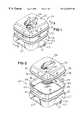
- FIG. 1is a perspective view of a household electric cooking appliance in accordance with this invention.
- FIG. 2is a partly exploded perspective view of the appliance of FIG. 1 .
- FIG. 3is simplified cross sectional view of the appliance taken along section line 3 — 3 of FIG. 1 .
- FIG. 4is a fragmentary front elevational view of a heating control panel forming part of the appliance of FIG. 1 and on a larger scale than FIG. 1 .
- FIG. 4also shows a thermostat control lever in cross section.
- FIG. 5is a bottom plan view of a steam release valve forming part of the appliance of FIG. 1 .
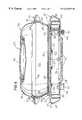
- FIG. 6is a perspective view of the appliance similar to FIG. 1 but showing the appliance assembled to form a compact assembly for storage.
- FIG. 6Ais a fragmentary cross-sectional view of the appliance assembled as shown in FIG. 6 and taken along section line 6 A— 6 A of FIG. 6 .
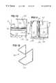
- FIG. 7is a partly exploded perspective view similar to FIG. 2 but showing the appliance parts in the orientations thereof when compactly assembled for storage.
- FIG. 8is a fragmentary front elevational view of the appliance compactly assembled for storage and showing the basic components thereof clamped together by a clamping strap.
- FIG. 9is a fragmentary perspective view of a portion of the clamping strap including one of two hooks by which the clamping strap can be connected to the griddle.
- FIG. 10is a fragmentary front elevational view of the appliance compactly assembled for storage and showing the basic components thereof held assembled together by a clip.
- FIG. 11is a fragmentary front elevational view of the appliance compactly assembled for storage, held by the clip, and standing on one of its sides.
- FIG. 12is a perspective view of the clip of FIGS. 10 and 11.
- FIG. 13is a partly diagrammatic, partly fragmentary top plan view of the griddle of the appliance of FIG. 1 .
- FIG. 14is a rear elevational view of the griddle of FIG. 13, as viewed in the direction of arrows 14 — 14 of FIG. 13 .
- a household electric cooking appliancegenerally designated 20 , in accordance with this invention comprises three basic components, a griddle 22 , a skillet 24 and a skillet lid 26 .
- the griddle 22is provided with a horizontal griddle plate 28 which is sized and shaped to interfit with the skillet 24 and the skillet lid 26 .
- Griddle plate 28is mounted on a griddle base 30 as by plural stanchions 32 , only one of which is shown in FIG. 3, at a height which provides an air gap 34 between the outer margins of the griddle plate 28 and the top of the griddle base 30 .
- Griddle base 30preferably comprises a molded plastic body having a central opening 36 covered by a sheet metal panel 38 . Openings or louvers 40 formed in the panel 38 and openings (not shown) in adjacent portions of the griddle base 30 admit ambient air into the chamber, designated 42 , below the griddle plate 28 . The admitted air flows upwardly through the chamber 42 and outwardly through the air gap 34 and thereby prevents the building up of excessive heat in the griddle base 30 .
- the griddle plate 28is generally square with gently curving, arcuately convex sides 44 .
- the upper surface of the griddle plate 28has a substantially planar cooking surface 45 bounded by an upwardly-projecting, low profile, inverted V-shaped, marginal flange 46 that forms the entire outer periphery of the griddle plate 28 .
- the griddle 22is supported in a horizontal orientation by plural feet 48 which preferably are provided with non-skid elastomeric buttons 50 adapted to contact a kitchen counter or other supporting surface.
- a sinuous calrod heating element 52 shown in cross section in FIG. 3 and in phantom in FIG. 13is used to heat the griddle plate 28 under the control of an adjustable thermostat 54 , shown diagrammatically in FIG. 13 .
- the thermostat 54is mounted on the bottom of the griddle plate 28 and connected to a source of household electric current by a power cord 56 .
- Manual adjustment of the thermostat 54is obtained by rotating a pivotal thermostat control lever 58 that projects outwardly through a horizontal-extending slot 60 in a heating control panel 62 at the front of the griddle 22 .
- a heating control knob 63shown in FIGS. 1 and 2, for example, is mounted on the outer, free end of the control lever 58 . The knob 63 is not shown in FIG.
- the circuit for heating the griddle plate 28can be entirely conventional and is not further described herein.
- the circuitincludes a neon lamp 65 visible from the front of the griddle base 30 which is lit whenever the heating element 52 is energized.
- Griddle 22is a fully functional household electric appliance by itself and can be used as one would use a conventional griddle, such as for preparing pancakes or frying eggs.
- a pair of mutually-spaced griddle handles 64are integrally molded to the opposite sides of the griddle base 30 .
- Each griddle handle 64includes a finger-engageable plate portion 66 that extends over a downwardly-opening handle cavity 68 .
- One using the griddle 22can easily lift the griddle 22 by inserting their fingers into the handle cavities 68 and lifting upwardly against the bottom surfaces of the handle plate portions 66 .
- the skillet 24comprises a pan 80 and mutually oppositely-extending and spaced handles 82 connected to the pan 80 by screws (not shown).
- Pan 80has a flat bottom wall 83 which is substantially square but for sides which curve convexly outwardly to approximate the shape of the planar cooking surface 45 of the griddle plate 28 .
- the skillet pan 80also includes upwardly and outwardly sloping walls 84 and 86 that join one another at rounded corners. Walls 84 are considered to be sidewalls because the skillet handles 82 are mounted thereon. Walls 86 are considered to be front and back walls.
- an outwardly and upwardly sloping flange or lip 88extends around the entire periphery of the top of the pan 80 along the uppermost edges of the walls 84 and 86 .
- the skillet 24is placed on top of the horizontal planar portion of the griddle plate 28 .
- the griddle 22is energized, foods to be heated in the skillet are heated by the conduction of heat from the griddle plate 28 through the bottom wall 83 of the skillet pan 80 .
- the griddle 22can be energized either before or after the skillet is placed thereon.
- the bottom wall 83 of the skillet pan 80is located within the inside margins of the peripheral griddle plate flange 46 . Accordingly, the griddle plate flange 46 prevents the skillet 24 from accidentally sliding laterally in any direction off the griddle plate 28 .
- the lid 26comprises a one-piece body member 90 to which a lid handle 92 is connected.
- the outer, bottom portion of the lid 26has a generally square lower edge 94 of a size and shape complementary to the top of the skillet pan 80 to fit rather snugly inside the top of the skillet pan 80 .
- the skillet lid 26has a peripherally-extending flange 96 located slightly above the lower edge 94 .
- the lid flange 96is formed in part by a curved, downwardly facing, outer, skillet-engaging surface 98 that extends upwardly and outwardly from the lower lid edge 94 . As shown best in FIG.
- the skillet-engaging surface 94 of the lid 26engages the skillet flange 88 at the top of the skillet 24 so that there is a substantial area of engagement between the skillet lid 26 and the skillet 24 . Accordingly, when used, the lid 26 snugly engages the skillet 24 .
- the upper wall portion of the skillet lid 26has an elongate, concave depressed portion to which the lid handle 92 is connected, as by the illustrated screws (FIG. 3 ). It will be noted that the lid handle 92 extends only slightly above the surrounding upper wall portions of the lid 26 so that the lid handle 92 does not appreciably add to the overall height of the lid 26 .
- a steam vent 100 of conventional constructionis provided.
- the ventincludes a slot 102 in the upper wall of the lid 26 and a valve member 104 having a manually-accessible stem 106 .
- the heating control panel 62is provided with two sets of temperature-indicating indicia, namely a lower, griddle temperature-indicating indicia set 110 located below the horizontal slot 60 and an upper, skillet temperature-indicating indicia set 112 located above the slot 60 . It will be observed that the lower indicia set 110 is marked with higher temperatures than the upper indicia set. This is because the lower indicia set 110 is used to set the thermostat 54 to the desired temperature of the griddle plate 28 when the griddle 22 is being used by itself.
- the upper indicia set 112is used to set the thermostat 54 to the desired temperature of the skillet 24 when the griddle 22 is used as a support and a heat source for the skillet 24 .
- the differences in the temperatures indicated by the two sets of indiciareflect the heat losses occurring when the bottom of the skillet 24 is being heated by the griddle plate 28 .
- the leftmost indiciais “off” and the thermostat preferably includes an on/off switch.
- the “off” position of the control lever 58is the same for both sets of indicia 110 and 112 .
- FIGS. 6, 6 a and 7illustrate a preferred method for stacking the basic components of the appliance 20 for storage.
- the skillet lid 26is assembled on top of the griddle 22 and the skillet 24 is inverted and stacked on top of the skillet lid 26 .
- FIG. 6Ait will be observed that the lower skillet lid edge 94 engages an upwardly-facing ledge 120 formed on the griddle base 30 that extends beneath and completely around the outside the outer margin of the griddle plate 28 . Accordingly, the skillet lid 26 is supported in a stable position on the griddle base 30 .
- the skillet lid flange 96has an upwardly-facing, curved outer surface 122 that is complementary to the skillet flange 88 so that the inverted skillet is supported in a stable position on top of the skillet lid flange 96 .
- the overall height of the appliance 20 when stacked for storage in the manner illustrated in FIGS. 6, 6 A and 7is significantly shorter than when the appliance 20 is stacked during ordinary use, as illustrated in FIGS. 1, 2 and 3 .
- the abutting surfaces of the skillet 24 and its lid 26include mating, complementarily curved surfaces that resist relative horizontal motion between them whether the appliance 20 is stacked for use as a skillet or stacked for storage. Accordingly, the stacked appliance 20 is resistant to being accidentally unstacked. In fact, all three basic components, the griddle 22 , the skillet 24 and the skillet lid 26 are such that horizontal movements of the skillet 24 and the lid 26 in any direction are substantially resisted whether the appliance 20 is stacked for use as a skillet or stacked for storage. In this sense the appliance 20 advantageously has considerable stability.
- the skillet 24 and the lid 26are so constructed that the appliance 20 could be rendered vertically compact by assembly of the skillet 24 and the lid 26 in ways other than shown in FIGS. 6, 6 A and 7 , provided that the top of the skillet lid is located within the skillet.
- the skillet and the skillet lidwould be stacked on the griddle in every case.
- the lid 26could be inverted from the position thereof shown in FIG. 3 so that the bottom of the lid 26 faces upward and the lid 26 is mostly received within the skillet 24 .
- the compact assembly shown in FIGS. 6, 6 A and 7is preferred because it is aesthetically pleasing and considered easier to handle than other assemblies.
- the compactly assembled appliance 20if stacked in the preferred manner, has a flat upper surface formed by the bottom wall 83 of the skillet 24 . If the compactly assembled appliance 20 is stored in a horizontal orientation, other items could be stored atop its flat upper surface.
- FIGS. 8 and 9illustrate the clamping together of the griddle 22 , the skillet 24 and the skillet lid 26 by the use of an elongate, resilient strap 130 which is provided with a hook 132 at each end.
- one of the hooks 132is inserted into the griddle handle cavity 68 of one of the griddle handles 64 on one side of the griddle 22 .
- the strap 130is stretched over the top of the inverted skillet 24 and hooked onto the griddle handle 64 on the opposite side of the appliance 20 in the same manner.
- the parts of the appliance 20are thereby clamped together and form a unitary module which is easy to handle and can conveniently be stored in confined storage areas as described above.
- FIG. 9illustrates one method of connecting the hooks 132 to the ends of the strap 130 .
- an end of the strap 130is inserted through a slot 134 in the hook 132 , looped back on itself and then connected to itself by stitching 136 .
- FIGS. 10, 11 and 12illustrate the use of a U-shaped clip, generally designated 140 , formed from stiff wire rod.
- the clip 140has a first, griddle-engaging, U-shaped section 142 and a second, skillet-engaging, U-shaped section 144 . Sections 142 and 144 are joined by a pair of mutually parallel support legs 146 .
- the clip 140may be used as a clamp, it need not tightly engage the appliance 20 provided that it prevents the basic components of the appliance 20 from becoming substantially separated.
- the clip 140can be slipped over the back of the appliance 20 , as shown in FIG.
- the appliance 20can then be stood on the back wall surfaces thereof as shown in FIG. 11 .
- Setting the appliance 20 on its back wall surfacesis preferred because the back walls of all three components form continuous, unbroken surfaces whereas the side wall surfaces of the griddle 22 and the skillet 24 are interrupted by the handles and the front wall of the griddle is interrupted by the control panel 62 .
- the clip 140can be placed on a horizontal supporting surface with its sections 142 and 144 vertically oriented and the compactly-assembled appliance 20 lowered between the sections 142 and 144 and onto the support legs 146 .
- the clip 140can be used instead of the clamping strap 130 of FIGS. 8 and 9.
- the clamping strap 130can be assembled onto the compactly-assembled appliance 20 before the clip 140 and the appliance 20 are assembled together.
- FIGS. 10 through 14show pads 150 located along the back side of the griddle 22 .
- Pads 150are intended to contribute to the supporting of the appliance 20 in the manner shown in FIG. 11 .
- the pads 150may assist in placing the appliance 20 in the upright manner shown in FIG. 11 .
- the appliance 20may tend to tip over from its upright orientation so that the primary support for the appliance will more likely come from the clip 140 and, perhaps, the lower edge of the appliance 20 .
- the appliance 20can be placed in an upright orientation without the use of the clip 140 provided that the appliance is clamped by the strap 130 or other suitable clamp and can lean against a vertical surface, such as a cabinet sidewall.
- the griddlecould be modified, such as by the provision of added pads 150 or by changing components such the the appliance 20 can be placed on one of its sides and remain erect without the use of a clip or other prop to maintain the erect position of the appliance 20 .
- the griddle plate 28 and the skillet pan 80are made from aluminum.
- the upper surface of the griddle plate 28 and the entire skillet pan 80are coated by a non-stick teflon coating or the like.
- the griddle base 30 , the griddle handles 64 , and the skillet handles 82are molded from a phenolic resin.
- the skillet lid 26is made from a high temperature thermosetting plastic resin and its handle 92 made from PBT resin.
- the steam vent valveis made from a polycarbonate material. Others familiar with the construction of cooking appliances will recognize that various materials different from those set forth above may be used.
- the generally square shapes of the griddle 22 , the skillet 24 and the skillet lid 26 illustrated in the drawingsis presently preferred, but other shapes of these components, such as generally oval shapes, generally rectangular shapes other than square, irregular shapes, or generally round shapes, would also be satisfactory.
Landscapes
- Engineering & Computer Science (AREA)
- Food Science & Technology (AREA)
- Baking, Grill, Roasting (AREA)
- Cookers (AREA)
Abstract
Description
Claims (21)
Priority Applications (3)
| Application Number | Priority Date | Filing Date | Title |
|---|---|---|---|
| US09/255,419US6443052B1 (en) | 1999-02-22 | 1999-02-22 | Household electric cooking appliance and apparatus for assembling and storing the appliance |
| AU33716/00AAU3371600A (en) | 1999-02-22 | 2000-02-22 | Household electric cooking appliance and method of storing |
| PCT/US2000/004422WO2000049928A1 (en) | 1999-02-22 | 2000-02-22 | Household electric cooking appliance and method of storing |
Applications Claiming Priority (1)
| Application Number | Priority Date | Filing Date | Title |
|---|---|---|---|
| US09/255,419US6443052B1 (en) | 1999-02-22 | 1999-02-22 | Household electric cooking appliance and apparatus for assembling and storing the appliance |
Publications (1)
| Publication Number | Publication Date |
|---|---|
| US6443052B1true US6443052B1 (en) | 2002-09-03 |
Family
ID=22968247
Family Applications (1)
| Application Number | Title | Priority Date | Filing Date |
|---|---|---|---|
| US09/255,419Expired - LifetimeUS6443052B1 (en) | 1999-02-22 | 1999-02-22 | Household electric cooking appliance and apparatus for assembling and storing the appliance |
Country Status (3)
| Country | Link |
|---|---|
| US (1) | US6443052B1 (en) |
| AU (1) | AU3371600A (en) |
| WO (1) | WO2000049928A1 (en) |
Cited By (17)
| Publication number | Priority date | Publication date | Assignee | Title |
|---|---|---|---|---|
| US6789465B2 (en)* | 2002-04-17 | 2004-09-14 | Carrier Commercial Refrigeration, Inc. | Grilling surface |
| US20050173402A1 (en)* | 2004-01-09 | 2005-08-11 | The Holmes Group, Inc. | Slow cooker and stand |
| US20070137499A1 (en)* | 2005-11-23 | 2007-06-21 | Sunbeam Products, Inc. | Cooking appliance with removable cooking surface |
| US20070175886A1 (en)* | 2006-02-02 | 2007-08-02 | Hamilton Beach/Proctor-Silex, Inc. | Slow cooker |
| US20070210055A1 (en)* | 2004-09-24 | 2007-09-13 | Claus Konrad | Regenerating equipment |
| GB2449238A (en)* | 2007-05-12 | 2008-11-19 | Leslie Chandler | A hot plate and cooking vessel |
| US20090025567A1 (en)* | 2007-07-24 | 2009-01-29 | Joshua Greenberg | Folding leg system for a cooking appliance |
| US20100180776A1 (en)* | 2007-01-17 | 2010-07-22 | Tsann Kuen(China) Enterprise Co., Ltd | Lifting-cover type frying-roasting device |
| US20110168026A1 (en)* | 2008-10-03 | 2011-07-14 | Nestec S.A. | User friendly interface for a beverage machine |
| US20120024164A1 (en)* | 2009-05-11 | 2012-02-02 | Jae-Hyoun Park | Cooking appliance |
| US20130153581A1 (en)* | 2011-12-16 | 2013-06-20 | Ryan H. Barrows | Countertop appliance having detachable base |
| US20140345476A1 (en)* | 2013-01-14 | 2014-11-27 | Hamilton Beach Brands, Inc. | Sandwich making appliance and method of making a sandwich |
| US20150157172A1 (en)* | 2013-01-14 | 2015-06-11 | Hamilton Beach Brands, Inc. | Sandwich Making Appliance and Method of Making a Sandwich with the Same |
| US9370275B2 (en) | 2013-01-14 | 2016-06-21 | Hamilton Beach Brands, Inc. | Sandwich making appliance and method of making a sandwich with the same |
| US20180153343A1 (en)* | 2013-01-14 | 2018-06-07 | Hamilton Beach Brands, Inc. | Sandwich Making Appliance and Method of Making a Sandwich with the Same |
| JP2020028373A (en)* | 2018-08-21 | 2020-02-27 | タイガー魔法瓶株式会社 | Heating cooker |
| WO2024042916A1 (en)* | 2022-08-24 | 2024-02-29 | 株式会社マスダック | Souffle pancake producing method and device |
Families Citing this family (2)
| Publication number | Priority date | Publication date | Assignee | Title |
|---|---|---|---|---|
| CN108030405A (en)* | 2018-01-09 | 2018-05-15 | 天使翼(武汉)科技创业发展股份有限公司 | It is a kind of can Intelligent fixed time oven |
| CN114365958B (en)* | 2021-12-21 | 2024-01-16 | 缙云县艾康厨具有限公司 | Multifunctional separable frying pan and processing technology thereof |
Citations (12)
| Publication number | Priority date | Publication date | Assignee | Title |
|---|---|---|---|---|
| US907154A (en) | 1908-05-04 | 1908-12-22 | Daniel Lewis | Cooking-pan. |
| US2253927A (en)* | 1940-03-25 | 1941-08-26 | Ralph F Butler | Controlled temperature butter dish |
| US2605382A (en)* | 1949-10-26 | 1952-07-29 | West Bend Aluminum Co | Apparatus for cooking |
| US2978564A (en)* | 1958-12-31 | 1961-04-04 | Corning Glass Works | Electric hot plate |
| US3681568A (en)* | 1971-12-15 | 1972-08-01 | John Oster Mfg | Electrically heated cooking appliance |
| US4013869A (en)* | 1976-04-12 | 1977-03-22 | Maria Amelia Orts | Tortilla warmer and hydrater |
| USD247946S (en) | 1976-09-20 | 1978-05-23 | Dart Industries Inc. | Electric cooking base and vessel |
| CH604652A5 (en)* | 1975-12-10 | 1978-09-15 | Robert Grolimund | Spirit stove for keeping food warm |
| USD250626S (en) | 1976-07-09 | 1978-12-26 | Rival Manufacturing Company | Electric cooking utensil |
| US4210072A (en) | 1978-02-02 | 1980-07-01 | Ivano Pedrini | Portable cooking apparatus suitable as an oven or as a grill |
| US4544818A (en)* | 1982-07-29 | 1985-10-01 | Asahi Giken Kogyo Kabushiki Kaisha | Cooking utensil for induction cooking apparatus |
| US5656188A (en) | 1995-01-27 | 1997-08-12 | Janowiak; Steven M. | Stackable skillet with extendable side and adjustability features |
- 1999
- 1999-02-22USUS09/255,419patent/US6443052B1/ennot_activeExpired - Lifetime
- 2000
- 2000-02-22WOPCT/US2000/004422patent/WO2000049928A1/enactiveApplication Filing
- 2000-02-22AUAU33716/00Apatent/AU3371600A/ennot_activeAbandoned
Patent Citations (12)
| Publication number | Priority date | Publication date | Assignee | Title |
|---|---|---|---|---|
| US907154A (en) | 1908-05-04 | 1908-12-22 | Daniel Lewis | Cooking-pan. |
| US2253927A (en)* | 1940-03-25 | 1941-08-26 | Ralph F Butler | Controlled temperature butter dish |
| US2605382A (en)* | 1949-10-26 | 1952-07-29 | West Bend Aluminum Co | Apparatus for cooking |
| US2978564A (en)* | 1958-12-31 | 1961-04-04 | Corning Glass Works | Electric hot plate |
| US3681568A (en)* | 1971-12-15 | 1972-08-01 | John Oster Mfg | Electrically heated cooking appliance |
| CH604652A5 (en)* | 1975-12-10 | 1978-09-15 | Robert Grolimund | Spirit stove for keeping food warm |
| US4013869A (en)* | 1976-04-12 | 1977-03-22 | Maria Amelia Orts | Tortilla warmer and hydrater |
| USD250626S (en) | 1976-07-09 | 1978-12-26 | Rival Manufacturing Company | Electric cooking utensil |
| USD247946S (en) | 1976-09-20 | 1978-05-23 | Dart Industries Inc. | Electric cooking base and vessel |
| US4210072A (en) | 1978-02-02 | 1980-07-01 | Ivano Pedrini | Portable cooking apparatus suitable as an oven or as a grill |
| US4544818A (en)* | 1982-07-29 | 1985-10-01 | Asahi Giken Kogyo Kabushiki Kaisha | Cooking utensil for induction cooking apparatus |
| US5656188A (en) | 1995-01-27 | 1997-08-12 | Janowiak; Steven M. | Stackable skillet with extendable side and adjustability features |
Non-Patent Citations (5)
| Title |
|---|
| Fron and rear cover and pp. 200 & 201 of "General Merchandise Catalog 1990/1991" published by Best Products Co., Inc. |
| Front and rear covers and pp. 250-253 of "96-97 Jewelry, Gift and Home Catalog" published by Service Merchandise Co., Inc. |
| Good Housekeeping, Dec. 1973, p. 136, "Table Range", by Corning. |
| House and Garden, May 1973, p. 156, "Lazy Day Slo-Cooker", by West Bend. |
| See Information Disclosure Statement regarding offer for sale less than one year before filing of this application. |
Cited By (32)
| Publication number | Priority date | Publication date | Assignee | Title |
|---|---|---|---|---|
| US6789465B2 (en)* | 2002-04-17 | 2004-09-14 | Carrier Commercial Refrigeration, Inc. | Grilling surface |
| US20050173402A1 (en)* | 2004-01-09 | 2005-08-11 | The Holmes Group, Inc. | Slow cooker and stand |
| US7009149B2 (en)* | 2004-01-09 | 2006-03-07 | Jcs/Thg, Llc | Slow cooker and stand |
| US20070210055A1 (en)* | 2004-09-24 | 2007-09-13 | Claus Konrad | Regenerating equipment |
| US20070137499A1 (en)* | 2005-11-23 | 2007-06-21 | Sunbeam Products, Inc. | Cooking appliance with removable cooking surface |
| WO2007062194A3 (en)* | 2005-11-23 | 2007-11-08 | Sunbeam Products Inc | Cooking appliance with removable cooking surface |
| US7872213B2 (en) | 2005-11-23 | 2011-01-18 | Sunbeam Products, Inc. | Cooking appliance with removable cooking surface |
| US20070175886A1 (en)* | 2006-02-02 | 2007-08-02 | Hamilton Beach/Proctor-Silex, Inc. | Slow cooker |
| US20100180776A1 (en)* | 2007-01-17 | 2010-07-22 | Tsann Kuen(China) Enterprise Co., Ltd | Lifting-cover type frying-roasting device |
| US8424449B2 (en)* | 2007-01-17 | 2013-04-23 | Tsann Kuen (Zhangzhou) Enterprise Co., Ltd. | Lifting cover type frying-roasting device |
| GB2449238B (en)* | 2007-05-12 | 2012-05-30 | Leslie Chandler | Hot plate and cook pot |
| GB2449238A (en)* | 2007-05-12 | 2008-11-19 | Leslie Chandler | A hot plate and cooking vessel |
| US20090025567A1 (en)* | 2007-07-24 | 2009-01-29 | Joshua Greenberg | Folding leg system for a cooking appliance |
| US20110168026A1 (en)* | 2008-10-03 | 2011-07-14 | Nestec S.A. | User friendly interface for a beverage machine |
| US20120024164A1 (en)* | 2009-05-11 | 2012-02-02 | Jae-Hyoun Park | Cooking appliance |
| US8925445B2 (en)* | 2009-05-11 | 2015-01-06 | Lg Electronics Inc. | Cooking appliance |
| US20130153581A1 (en)* | 2011-12-16 | 2013-06-20 | Ryan H. Barrows | Countertop appliance having detachable base |
| US9060640B2 (en)* | 2011-12-16 | 2015-06-23 | National Presto Industries, Inc. | Countertop appliance having detachable base |
| US10016092B2 (en) | 2011-12-16 | 2018-07-10 | National Presto Industries, Inc. | Countertop appliance having detachable base |
| US20140345476A1 (en)* | 2013-01-14 | 2014-11-27 | Hamilton Beach Brands, Inc. | Sandwich making appliance and method of making a sandwich |
| US20150157172A1 (en)* | 2013-01-14 | 2015-06-11 | Hamilton Beach Brands, Inc. | Sandwich Making Appliance and Method of Making a Sandwich with the Same |
| US9370275B2 (en) | 2013-01-14 | 2016-06-21 | Hamilton Beach Brands, Inc. | Sandwich making appliance and method of making a sandwich with the same |
| CN104188507B (en)* | 2013-01-14 | 2016-08-24 | 汉美驰品牌有限公司 | Sandwich is prepared utensil and utilizes its method preparing sandwich |
| US9462912B2 (en) | 2013-01-14 | 2016-10-11 | Hamilton Beach Brands, Inc | Sandwich making appliance and method of making a sandwich with the same |
| US20180153343A1 (en)* | 2013-01-14 | 2018-06-07 | Hamilton Beach Brands, Inc. | Sandwich Making Appliance and Method of Making a Sandwich with the Same |
| US10010216B2 (en) | 2013-01-14 | 2018-07-03 | Hamilton Beach Brands, Inc. | Sandwich making appliance and method of making a sandwich with the same |
| CN104188507A (en)* | 2013-01-14 | 2014-12-10 | 汉密尔顿毕克布兰德斯有限公司 | Sandwich Making Appliance and Method of Making a Sandwich with the Same |
| US10244893B2 (en)* | 2013-01-14 | 2019-04-02 | Hamilton Beach Brands, Inc. | Sandwich making appliance and method of making a sandwich with the same |
| JP2020028373A (en)* | 2018-08-21 | 2020-02-27 | タイガー魔法瓶株式会社 | Heating cooker |
| WO2024042916A1 (en)* | 2022-08-24 | 2024-02-29 | 株式会社マスダック | Souffle pancake producing method and device |
| JP2024030658A (en)* | 2022-08-24 | 2024-03-07 | 株式会社マスダック | Souffle pancake manufacturing method and device |
| TWI883505B (en)* | 2022-08-24 | 2025-05-11 | 日商馬獅達克股份有限公司 | Soufflé pancake manufacturing method and device |
Also Published As
| Publication number | Publication date |
|---|---|
| AU3371600A (en) | 2000-09-14 |
| WO2000049928A8 (en) | 2001-03-15 |
| WO2000049928A1 (en) | 2000-08-31 |
Similar Documents
| Publication | Publication Date | Title |
|---|---|---|
| US6443052B1 (en) | Household electric cooking appliance and apparatus for assembling and storing the appliance | |
| US6603099B2 (en) | Multifunction electrical cooking appliance | |
| US5203252A (en) | Toaster with multi-function | |
| US6188046B1 (en) | Food-heating appliance and method of using same | |
| US4476848A (en) | Countertop oven | |
| US4889972A (en) | Multi-functional electrically activated stove | |
| CN1118261C (en) | Freestanding cooking utensils that can be used on both sides | |
| US6186055B1 (en) | Turntable cooking and serving appliance | |
| US7090094B2 (en) | Handle for cookware | |
| US20110081471A1 (en) | Cooking Apparatus | |
| EP0696430A1 (en) | Multi-function electric home appliance | |
| CA2578254C (en) | Slow cooker and stand | |
| CA2747968A1 (en) | Portable cooking system | |
| US6369367B1 (en) | Cooking apparatus | |
| US20030180426A1 (en) | Bacon cooker | |
| CN221265924U (en) | Base assembly of cooking utensil and cooking utensil | |
| KR200209637Y1 (en) | Pedestal heater | |
| CN222443896U (en) | Base assembly of cooking utensil and cooking utensil | |
| CN211432388U (en) | Cooking utensil and pot body thereof | |
| CN213248344U (en) | Cooking utensil | |
| CN219661469U (en) | Steam grill assembly | |
| CN223286958U (en) | Pot body assembly and cooking utensil | |
| CN219353687U (en) | Compact multifunctional toaster | |
| JP3479520B2 (en) | Kitchen rack | |
| CN212521548U (en) | Air fryer is with frying bucket subassembly |
Legal Events
| Date | Code | Title | Description |
|---|---|---|---|
| AS | Assignment | Owner name:HAMILTON BEACH/PROCTOR-SILEX, INC., VIRGINIA Free format text:ASSIGNMENT OF ASSIGNORS INTEREST;ASSIGNORS:GARBER, ALAN M.;BROOKSHIRE, PHILLIP L.;SLAYTON, DAVID L.;REEL/FRAME:010106/0221;SIGNING DATES FROM 19990611 TO 19990712 | |
| AS | Assignment | Owner name:HAMILTON BEACH/PROCTOR-SILEX, INC., VIRGINIA Free format text:ASSIGNMENT OF ASSIGNORS INTEREST;ASSIGNORS:GARBER, ALAN M.;BROOKSHIRE, PHILLIP L.;SLAYTON, DAVID L.;AND OTHERS;REEL/FRAME:010347/0457;SIGNING DATES FROM 19991011 TO 19991020 | |
| STCF | Information on status: patent grant | Free format text:PATENTED CASE | |
| AS | Assignment | Owner name:WACHOVIA BANK, N.A., AS AGENT, NORTH CAROLINA Free format text:NOTICE OF GRANT OF SECURITY INTEREST;ASSIGNOR:HAMILTON BEACH/PROCTOR-SILEX, INC.;REEL/FRAME:013616/0753 Effective date:20021217 | |
| FEPP | Fee payment procedure | Free format text:PAYOR NUMBER ASSIGNED (ORIGINAL EVENT CODE: ASPN); ENTITY STATUS OF PATENT OWNER: LARGE ENTITY | |
| FPAY | Fee payment | Year of fee payment:4 | |
| AS | Assignment | Owner name:UBS AG, STAMFORD BRANCH, AS AGENT, CONNECTICUT Free format text:SECURITY AGREEMENT;ASSIGNOR:HAMILTON BEACH/PROCTOR-SILEX, INC.;REEL/FRAME:019399/0687 Effective date:20070531 | |
| AS | Assignment | Owner name:HAMILTON BEACH BRANDS, INC., VIRGINIA Free format text:CHANGE OF NAME;ASSIGNOR:HAMILTON BEACH/PROCTOR-SILEX, INC.;REEL/FRAME:020174/0160 Effective date:20070928 Owner name:HAMILTON BEACH BRANDS, INC.,VIRGINIA Free format text:CHANGE OF NAME;ASSIGNOR:HAMILTON BEACH/PROCTOR-SILEX, INC.;REEL/FRAME:020174/0160 Effective date:20070928 | |
| FPAY | Fee payment | Year of fee payment:8 | |
| AS | Assignment | Owner name:HAMILTON BEACH BRANDS, INC., FORMERLY KNOWN AS HAM Free format text:RELEASE BY SECURED PARTY;ASSIGNOR:UBS AG, STAMFORD BRANCH;REEL/FRAME:028309/0439 Effective date:20120531 | |
| AS | Assignment | Owner name:WELLS FARGO BANK, NATIONAL ASSOCIATION, NEW YORK Free format text:SECURITY INTEREST;ASSIGNOR:HAMILTON BEACH BRANDS, INC.;REEL/FRAME:028372/0853 Effective date:20120531 | |
| FPAY | Fee payment | Year of fee payment:12 |