US6442999B1 - Leak locator for pipe systems - Google Patents
Leak locator for pipe systemsDownload PDFInfo
- Publication number
- US6442999B1 US6442999B1US09/815,099US81509901AUS6442999B1US 6442999 B1US6442999 B1US 6442999B1US 81509901 AUS81509901 AUS 81509901AUS 6442999 B1US6442999 B1US 6442999B1
- Authority
- US
- United States
- Prior art keywords
- sonic
- pipe
- time
- leak
- measure
- Prior art date
- Legal status (The legal status is an assumption and is not a legal conclusion. Google has not performed a legal analysis and makes no representation as to the accuracy of the status listed.)
- Expired - Lifetime
Links
Images


Classifications
- G—PHYSICS
- G01—MEASURING; TESTING
- G01F—MEASURING VOLUME, VOLUME FLOW, MASS FLOW OR LIQUID LEVEL; METERING BY VOLUME
- G01F1/00—Measuring the volume flow or mass flow of fluid or fluent solid material wherein the fluid passes through a meter in a continuous flow
- G01F1/66—Measuring the volume flow or mass flow of fluid or fluent solid material wherein the fluid passes through a meter in a continuous flow by measuring frequency, phase shift or propagation time of electromagnetic or other waves, e.g. using ultrasonic flowmeters
- G—PHYSICS
- G01—MEASURING; TESTING
- G01M—TESTING STATIC OR DYNAMIC BALANCE OF MACHINES OR STRUCTURES; TESTING OF STRUCTURES OR APPARATUS, NOT OTHERWISE PROVIDED FOR
- G01M3/00—Investigating fluid-tightness of structures
- G01M3/02—Investigating fluid-tightness of structures by using fluid or vacuum
- G01M3/04—Investigating fluid-tightness of structures by using fluid or vacuum by detecting the presence of fluid at the leakage point
- G01M3/24—Investigating fluid-tightness of structures by using fluid or vacuum by detecting the presence of fluid at the leakage point using infrasonic, sonic, or ultrasonic vibrations
- G01M3/243—Investigating fluid-tightness of structures by using fluid or vacuum by detecting the presence of fluid at the leakage point using infrasonic, sonic, or ultrasonic vibrations for pipes
- G—PHYSICS
- G01—MEASURING; TESTING
- G01N—INVESTIGATING OR ANALYSING MATERIALS BY DETERMINING THEIR CHEMICAL OR PHYSICAL PROPERTIES
- G01N2291/00—Indexing codes associated with group G01N29/00
- G01N2291/02—Indexing codes associated with the analysed material
- G01N2291/028—Material parameters
- G01N2291/02836—Flow rate, liquid level
Definitions
- This disclosurerelates to sensing systems and more particularly, to a system for sensing a location of a leak in a pipeline system.
- pipelinesare under some degree of pressure, either from the pumping of the gas or liquid, or by the effect of gravity. Accordingly, when a pipeline ruptures, it is generally accompanied by the reduction of pressure at the point of the leak. This generates a low-pressure wave that travels in both directions, at the speed of sound in the medium, plus or minus the effect of actual flow rate in the downstream and upstream directions respectively.
- leaksmay be detected at monitoring stations, which are distributed at intervals along the pipeline. Changes in pressure or flow rate are detected and anomalies are determined to determine leaks in the pipeline. Pressure changes are determined between monitoring stations; however, with conventional detection systems when the leak has first occurred is not known. Accordingly, location of the leak is difficult to determine with the accuracy needed for a quick response. With conventional systems, a leak's location can be determined in a region on the order of hundreds of meters (e.g., 150 to 200 meters).
- a system and method which defines the location in a pipeline, at which a leak has occurred, with very high precision, using the detection of the low-pressure wave resultant from the leakis disclosed.
- the low-pressure wavetravels at the speed of sound in the liquid or gas in the pipeline in both upstream and downstream directions.
- Site stations that can detect the arrival time of the pressure waveare located at opposite ends of the pipeline segment. The Site Stations detect the arrival time of the low-pressure wave non-intrusively, and with great precision.
- GPSglobal positioning system
- a system and method for determining a time of occurrence of a pressure wave in a pipeprovides a first sonic transducer and a second sonic transducer at each of a plurality of site locations along a pipe. Sonic waves are generated through a pipewall at a known desired rate. At each of the plurality of site locations, the sonic waves travel from the first sonic transducer to the second sonic transducer through a liquid flow in the pipe. A measure of travel time is set for the sonic waves. The measure is compared to each of the successive travel times for the sonic waves as the sonic waves arrive at the respective second transducers. A string of counts is output at each second transducer. Each count includes a first count value if a present sonic wave has a travel time that is late as compared to the measure.
- a time of occurrence of the pressure waveis determined based on a reference clock when the string of counts includes a string of first count values longer than a threshold value.
- the time of occurrence of a pressure transientis indicated by a first count in the string of first count values.
- the time of occurrenceis employed in accurately calculating the position of a leak, hot tap or malfunctioning valve, pump, etc.
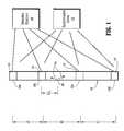
- FIG. 1is a schematic diagram of a pipe system having a leak detection system installed in accordance with the present invention
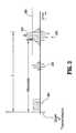
- FIG. 2is a cross-sectional view of the pipe system of FIG. 1 showing greater detail of sonic energy waves traveling in the pipe at a site station in accordance with the present invention
- FIG. 3depicts a time line of signals generated by transducers of FIG. 2 in accordance with the present invention.
- FIG. 4shows a plot in accordance with the present invention indicating one and zero reports to establish when a leak has occurred
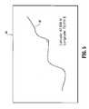
- FIG. 5shows a pipeline map which correlates distances with positions on a pipeline system in accordance with the present invention.
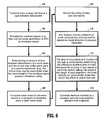
- FIG. 6is a block/flow diagram for a system/method for determining the time of occurrence of a pressure and/or detecting leaks in the pipe system in accordance with the present invention.
- the present inventionincludes a system and method for measuring pressure transients in a flow within a pipe.
- the present inventionprovides a new and very precise way of locating the place where a leak has occurred on a pipeline, which transports liquids, such as hydrocarbons or other types of liquid.
- the present inventionprovides a precision of less than several meters, and preferably, under 1 meter is determining the location of a leak.
- System 10includes a plurality of monitoring or site stations 12 a - 12 d , generally referred to as site stations 12 hereinafter, which monitor occurrences within pipe system 10 .
- site stations 12each preferably include a wide beam transit-time ultrasonic flow meter 14 , as described in U.S. Pat. No. 5,117,698, incorporated herein by reference.
- Flow meter 14may include a clamp-on type, which clamps to an exterior wall of a pipe 16 to permit flow characteristics to be measured in pipe 16 .
- Flow meters 14may be adapted to monitor flow characteristics at site stations 12 .
- clamp-on wide beam transit-time ultrasonic flow meter 14includes a set of ultrasonic transducers.
- a transducer 20is employed to transmit wide beam ultrasonic signals into pipe 16 and flow 24 .
- a transducer 22is employed to receive wide beam ultrasonic signals from pipe 16 and flow 24 .
- the transmitted sonic energy in the form of a wide beam 26travels across pipe 16 and is measured by transducer 22 .
- a computer or data acquisition device 25may be employed with flow meter 14 to perform computations to determine flow rates, proportions of the constituents material of flow 24 , storing lookup tables or other parameters needed to determine characteristics of flow 24 .
- a natural mode of sonic energy transmissionis excited in pipe 16 , in which a transverse wave 30 travels axially down the pipe wall at the velocity characteristic of the pipe's material, and at a frequency dependent on the pipe material and a wall thickness “t”.
- wave 30When such a wave 30 is generated, as it travels down the pipe wall, wave 30 radiates a sonic wave 32 into the flow 24 , which ultimately reflects off the far wall and reenters the pipe wall on the same side of the pipe from which is was originally transmitted.
- the sonic energythen enters this receive transducer 22 and generates a receive signal.
- one principle of operation for the present inventionis the detection of the change in liquid density associated with the lowering of pipeline pressure caused by a leak at, e.g., location 40 .
- This low-density transient wave 41propagates both upstream and downstream from the point of the leak at the velocity at which sound travels through the liquid(s).
- measuring station 12 brecords the transient with a time resolution of, e.g., between 1 and 2 milliseconds for a transmission rate of about 1000 pulses per second.
- Clamp-on ultrasonic flowmeter 14senses the sonic propagation velocity of the medium in pipe 16 . It does so by measuring the time that it takes for a sonic pulse 32 to travel over a known path length through the medium, generally a diagonal path from the transmitting transducer 20 that reflects diagonally from the opposite side of the pipe to be detected by the receive transducer 22 .
- the clamp-On ultrasonic flowmeter 14has the ability to sense the change in pressure caused by a leak, as the pressure wave arrives from the point of the leak, traveling at the speed of sound, to the location of the flowmeter site station 12 (FIG. 1 ). Since it is not required that the site station measure flow, a freestanding ultrasonic pressure wave detector may be employed in an alternate embodiment.
- Each measuring site station 12is synchronized by a common clock or synchronization device 15 .
- synchronization device 15may include a zero latency communication system, WWV or global positioning system (GPS) technology.
- a synchronizing pulseis sent to or maintained at each station 12 .
- the common clock signalprovides a frame of reference for a leak detection position as will be described in detail below.
- any spurious high frequency transientswhose wavelength is shorter than the sonic beam path length, will have their effect integrated out of the detection range of the ultrasonic pressure wave detector of the present invention. Since, in a pipe of, say, 12 inches diameter, filled with, say, Crude Oil, the path length is about one meter, and the sonic propagation velocity can be, say, 1400 meters per second, any spurious wave with a frequency of higher than about 1400 Hz will be filtered out.
- the system describedwill be able to detect the transient change of sonic propagation velocity caused by a leak induced low pressure wave, and be free of the disruptive effects of anomalous pressure waves endemic to a pipeline.
- a site station 12includes a means of generating a sonic interrogation pulse into the pipeline at least every millisecond. On reception of the sonic pulse, it will be determined how long it took for the pulse to arrive, from the time of its transmittal.
- each site station 12transmits ultrasonic pulses into the pipe wall by use of wide beam clamp-on transducer 20 .
- This pulseenters the liquid and travels in such a way as to ultimately pass through the pipe wall and reflect back to the side of transducer 22 .
- the pipewallacts as a beam splitter, splitting the ultrasonic beam between the pipewall and the flow.
- Transducer 22detects the ultrasound pulse and conveys a signal (receive signal) at site stations 12 .
- the arrival time of the signaldepends on the sonic propagation velocity of the liquid flow 24 in pipe 16 . Sonic propagation velocities of sound in liquids are a function of the liquid's density.
- the arrival time of the sonic pulseswill be suddenly extended.
- the extension of the sonic pulsesis employed in the present invention to accurately determine the time of occurrence of the leak (or drop in pressure) and the location of the leak.
- Site station 12amplifies the received transducer signal and digitizes its arrival time, e.g., relative to the travel time of the previously transmitted sonic pulse.
- a time reference or measure(see FIG. 3) is established for the arrival time of the signal prior to the arrival of a low-density (e.g., leak transient) wave.
- the referenceis created by setting a reference in normal or stable flow conditions.
- the receive signalmay have a “marker” embedded in the receive signal or a portion of the receive signal may be employed as a reference which is used as a discrete time location to be compared to a measure value. If the liquid sonic velocity is changing due to chemical or temperature causes, such density or sonic velocity changes are much slower than pressure transient causes, and so the alternate late or early outputs will occasionally see an extra late or early output to move the window so as to follow the slow time movement of the signal. The extra signals can be averaged out over time.
- FIG. 3an example of a late count is shown.
- the transmission of sonic wave 32 (FIG. 1) or signal 203produces a pipe wall signal 205 (wave 30 in FIG. 1 ).
- Envelope 202breaks a threshold line 206 at a point 207 beyond a threshold or measure time (labeled “Measure” in FIG. 3 ).
- Site station 12(FIG. 1) records the successive late/early counts and divides the counts into bit words.
- a synchronizing pulsearrives at, e.g., one-minute intervals, site station 12 transmits these words sequentially to a master station 44 . If there are 1,000 transmit pulses per second, in one minute there will have been 60,000 transmit pulses at the time that the next synchronizing pulse arrives. This provides that, at a 16-bit word density, 3750 16-bit bytes are be transmitted to master station 44 .
- a threshold line 206 in FIG. 3 or other referencemay be employed to define a position where signal 204 first arrived.
- the beginning of this sloped line or “cusp”marks the arrival time of the low-pressure wave in this example, however other references may be selected.
- Wide beam ultrasonic transducers 20 and 22 of FIG. 2operate as exciters of the pipe's sonic waveguide properties. These are dependent on the pipe's wall thickness and material, which together determine the desired frequency and phase velocity of the transducer.
- a transmittal form transducer 20 of from 3 to 5 pulses shown as signal 203a very large and “low Q” (fast response) envelope 202 is preferably generated at transducer 22 .
- the signal 204may be fully rectified or subjected to other wave shaping processes.
- the arrival time T of the signal 204is detected by digitally imaging the very sharp (low Q) shape of the received signal, and then using digital computation to analyzing the wave shape to identify the arrival time T of the very first “cusp” of the received signal 204 .
- This arrival time Tis digitally represented and fed into a register or other storage device, after being averaged, for example exponentially averaged.
- Exponential averagingin one embodiment is performed by subtracting the currently sensed arrival time T(current) from the previously exponentially averaged arrival time T(previous) and dividing the result by a large number, say from 3 to 10. The result of the division is then added or subtracted from a result of a prior exponential average (or previously assigned number) to establish a new average to be used for the next transmission. This has the effect of establishing a relatively stable value representing the arrival time for the current liquid under nominal conditions.
- the averaged number or stored register numberis a measure value (Measure in FIG. 3) against which the next arrival time T will be compared.
- a measure value(Measure in FIG. 3) against which the next arrival time T will be compared.
- Tarrival time
- a pulse with an arrival time (T) later than the Measureis coded as a “1” in a FIFO, and earlier is coded as a “0”.
- a FIFOmay empty its contents by transmitting the contents to a master station 44 (FIG. 1) or other reporting location, which will store the history of Early/Late results of the transmissions.
- the contents of the FIFOare periodically sent to master station 44 , in a time-synchronized fashion. They are preferably grouped into digital words and then compressed, so that, for example, the 60,000 ones or zeros collected in a one minute period, assuming a 1 millisecond pulse transmit rate, can be represented in about 500 bytes.
- master station 44may include a computer or other monitoring device which creates a display 70 in which, for example, each site station's data is displayed as a result of an integration or cumulative sum.
- Display 70shows integrated ones 71 and zeros 73 for a site station for a given synchronized time (e.g., one minute or other set amount of time) as a plot 72 .
- plot 72will be a relatively flat line 74 , near zero. If there is a leak, starting at the display time 76 that site station first started to receive the continuous ones caused by a leak, display 70 shows an integration of the ones, forming a linearly rising line 78 until a new average 79 is achieved. This permits identification of the exact time that the low-pressure transient arrived, to the millisecond. This also permits location of a leak to the order of magnitude of about 1 meter or better, dependent only on signal to noise ratio of the signal. Rising line 78 indicates a leak. Master station 44 may include characteristic curve data, which is compared to the sit station data to determine a leak. The duration and sizes of the plots can be compared to a reference value(s) or threshold to determine the severity or type of leak.
- the characteristic display of a leak transient, and durationmay be employed as a leak detector. However, leak detection may be performed by other means as well. In either case, master station 44 will show the characteristic sign of a leak on each of site stations bounding the segment on which the leak has occurred.
- the time synchronized display 70will show the relative arrival time at each of the segment's site stations 12 . The operator or software for each site station will be capable of determining when the first arrived “one”, was received after a pressure transient (display time 76 ).
- master station 44computes the location of the leak by a formula.
- An example of a formula which may be employed to compute the distance to a leakis shown as EQ. 1, which is based on the difference in absolute arrival times:
- V sliquid sonic propagation velocity
- V fflow velocity
- V sis employed in computing leak location. Those skilled in the art would understand, based on the present disclosure, how to perform an equivalent computation of leak location even when there are several batches of different liquids in the pipeline segment, each at different sonic propagation velocity.
- a time resolution of 1 millisecond or better in data collectionpermits a precision of leak location in the range of, for example, from 1 to 1.5 meters from the actual location 40 of the leak.
- Master station 44may continuously monitor pipeline 16 for leaks. This may be performed by triggering an alarm when a predetermined number of late counts are experienced. Alternately, a conventional leak detection system may be employed, which then instructs a remediation staff to determine the location of the leak. By consulting data at master station 44 , particularly inspecting the data stored for the period of time at which the leak is suspected of occurring, the leak's position can be accurately determined in accordance with the present invention.
- the resultant computationdefines the distance, Du between either of site stations 12 b or 12 c to the leak location 40 . Since pipelines are not always linear in their configuration, it would be advantageous to translate the distance indication into a particular longitude and latitude position.
- master station 44 or other locationincludes a map 80 of a pipeline 82 . Every point on pipeline 82 is translated into geographical coordinates, e.g., latitude and longitude. In the event of a leak, a location of the leak will be calculated and indicated on that map by a suitable marker, with the latitude and longitude displayed. Thus, an appropriate vehicle can be used to quickly transport a remediation crew to the site, by truck, helicopter, boat, etc. to remedy the leak.
- geographical coordinatese.g., latitude and longitude.
- a sequence of ones and zerosmay be employed to identify the sonic propagation velocity at any time. This is useful in determining the density of the product at each site station, as would be used for interface detection or product type and quality detection.
- transducer 20transmits sonic pulses 203 (FIG. 3) to transducer 22 at a predetermined rate.
- the transmissionproduces a pipe wall signal 205 (FIG. 3 ).
- the predetermined rateis 1,000 times per second. Other rates may be employed and have the effect of increasing (higher rate) or decreasing (lower rate) the precision of the system on the present invention.
- a reflected pipe wall signal 205(wave 32 of FIG. 2) is received by transducer 22 which processes signal 205 to generate a receive signal 204 (FIG. 3 ).
- the signal 204is full wave rectified and filtered to obtain a signal representing an envelope 202 as illustratively shown in FIG. 3 .
- an amount of time between transmission of a sonic wave and the arrival time of the sonic wave at the receive transduceris determined.
- a threshold level 206(FIG. 3) is set which is employed to indicate when the sonic wave has arrived at transducer 22 .
- the threshold level 206can be set in advance based on experience, based on amplification factors of the sonic signals, based on previously received signals, or a combination of factors.
- travel times for the sonic wavesare compared to a measure to determine early or later travel times.
- a travel timeis expressed as a number of clock cycles from transmission to receipt (e.g., the envelope 202 breaking threshold line 206 in FIG. 3 ). Travel times can be adapted to represent sonic conductivities when gas pipelines are employed.
- the measuremay be determined as an exponentially averaged quantity as described above. A determination is made to see if the newly arrived wave is later or early as compared to the measure.
- the low-pressure wave caused by the leaktravels upstream and downstream, being read, in block 110 , first by the nearest site stations 12 a , and then by the further site stations 12 b (FIG. 1 ). This permits a determination of the direction in which the pressure wave is traveling.
- the lower density and lower sonic velocity of the wavecauses the receive signal to move “late.”
- the exponential buffercatches up to a new position or average of the receive signal (the “new” measure position)
- the FIFOwill only receive “late” reports (e.g., a string of 1's).
- a string of late reportsindicates the change in flow, e.g., a transient pressure wave due to a leak in pipe 16 .
- the location and time of occurrence of the leakis computed by determining the difference in arrival time of a first “1” for the string of late reports (from the FIFO) at each site station, taking into account the length of each segment (e.g., distances A, B, C, etc.), the sonic velocity in the liquid and the effect of actual liquid flow rate (e.g., add the flow rate to the sonic velocity for a wave traveling with the flow, and subtracting the flow rate from the sonic velocity for a wave traveling against the flow).
- the digital 1's and 0's sequence or stringis used to identify the occurrence. EQ. 1, set forth above, may be employed.
- the sonic velocity of hydrocarbon liquidsis about 1 m/s, at least a 1 meter resolution is achievable for the location of the leak. This is a significant improvement over conventional systems, which have a precision of about 150 meter to 200 meters.
- While the system of the present inventionwill determine the linear distance from the segment's site stations where a leak has occurred, acting on this information is not simple if the pipeline is not linear. Especially on buried or underwater pipelines, locating the leak relative to its terrain markers, or its absolute location (GPS) may be needed. This is especially true if the pipeline is convoluted.
- GPSabsolute location
- distances traveled by a pressure wave along a pipelinemay be correlated to map positions, e.g., latitude and longitude positions.
- Master station 44(FIG. 1) may include a “Map” of the pipeline, with an algorithm that converts the distance from each surrounding Site Station to specific position, e.g., a latitude and longitude of the leak location. This may be combined with a Global Positioning System to mark the location on a GPS Map system which could guide trucks, helicopters, ships, etc. to the actual leak location.
- the system and methods of the present inventionmay be employed to quickly identify the locations of other anomalies, which may occur in pipeline system.
- the present inventionmay be employed to determine a location where a theft of product is being carried out, by, e.g., hot-tapping the pipeline.
- the present inventionwill identify the location of any pump or valve, which is being operated unsafely.
- a significant advantageis provided by the use of clamp-on ultrasonic transducers, in place of using pressure sensors to determine the arrival of a low-pressure leak wave.
- the sonic arrival time system of the present inventionintegrates out all the transients that have a wavelength smaller than the liquid path length of the sonic beam injected into the pipe. Thus, the sonic system has a greater dynamic range, and is more efficient in leak detection.
Landscapes
- Physics & Mathematics (AREA)
- General Physics & Mathematics (AREA)
- Electromagnetism (AREA)
- Fluid Mechanics (AREA)
- Examining Or Testing Airtightness (AREA)
Abstract
Description
Claims (20)
Priority Applications (1)
| Application Number | Priority Date | Filing Date | Title |
|---|---|---|---|
| US09/815,099US6442999B1 (en) | 2001-03-22 | 2001-03-22 | Leak locator for pipe systems |
Applications Claiming Priority (1)
| Application Number | Priority Date | Filing Date | Title |
|---|---|---|---|
| US09/815,099US6442999B1 (en) | 2001-03-22 | 2001-03-22 | Leak locator for pipe systems |
Publications (2)
| Publication Number | Publication Date |
|---|---|
| US6442999B1true US6442999B1 (en) | 2002-09-03 |
| US20020134140A1 US20020134140A1 (en) | 2002-09-26 |
Family
ID=25216849
Family Applications (1)
| Application Number | Title | Priority Date | Filing Date |
|---|---|---|---|
| US09/815,099Expired - LifetimeUS6442999B1 (en) | 2001-03-22 | 2001-03-22 | Leak locator for pipe systems |
Country Status (1)
| Country | Link |
|---|---|
| US (1) | US6442999B1 (en) |
Cited By (51)
| Publication number | Priority date | Publication date | Assignee | Title |
|---|---|---|---|---|
| WO2003048713A1 (en)* | 2001-11-30 | 2003-06-12 | The Victoria University Of Manchester | Remote pipeline acoustic inspection |
| US20040093172A1 (en)* | 2002-11-08 | 2004-05-13 | Hamanen Co., Ltd. | Method of estimating location of abnormality in fluid feed pipeline network |
| US20050252278A1 (en)* | 2004-05-11 | 2005-11-17 | Milbar Hydro-Test, Inc. | Hydrostatic test system and method |
| US20060065392A1 (en)* | 2004-09-24 | 2006-03-30 | Geo Estratos, S.A. De C.V. | System and method for crude oil production stemming from natural emanations and leaks from capped oil wells |
| US20060091876A1 (en)* | 2004-11-04 | 2006-05-04 | Geo Estratos, S.A. De C.V. | Leak detection method and system in nonmetallic underground pipes |
| US20060266198A1 (en)* | 2005-05-26 | 2006-11-30 | Jeffries Walter B | Snare drum accessory |
| US20070005250A1 (en)* | 2005-06-27 | 2007-01-04 | Geo Estratos, S.A. De C.V. | System and method for locating leaks in petroleum wells |
| US7219553B1 (en)* | 2003-09-11 | 2007-05-22 | Loren Worthington | Dynamic transient pressure detection system |
| DE102006001074A1 (en)* | 2006-01-09 | 2007-07-12 | Asi Aquasound Instruments Gmbh | Ultrasonic flow measuring system for e.g. river, has measuring devices with transmitting/receiving unit for wirelessly exchanging of data signals between devices, where each device has timer unit for wirelessly transmitting time signal |
| US20090000381A1 (en)* | 2007-06-26 | 2009-01-01 | General Electric Company | Acoustic impact detection and monitoring system |
| US7506688B2 (en) | 2005-09-07 | 2009-03-24 | Geo Estratos, S.A.De Cl.V. | System and method for breach detection in petroleum wells |
| US7698946B2 (en) | 2006-02-24 | 2010-04-20 | Caterpillar Inc. | System and method for ultrasonic detection and imaging |
| US7940189B2 (en) | 2005-09-29 | 2011-05-10 | Rosemount Inc. | Leak detector for process valve |
| US8069402B2 (en) | 2008-03-18 | 2011-11-29 | On-Ramp Wireless, Inc. | Error detection system |
| WO2012044435A1 (en) | 2010-09-30 | 2012-04-05 | Siemens Aktiengesellschaft | Pipeline leak location system and method |
| US20130253873A1 (en)* | 2012-03-22 | 2013-09-26 | First Sensor AG | Calibration of flowmeters |
| US20150002300A1 (en)* | 2013-06-27 | 2015-01-01 | Lg Cns Co., Ltd. | Real time remote leak detection system and method |
| US20150000380A1 (en)* | 2013-06-26 | 2015-01-01 | Lg Cns Co., Ltd. | Water leak sensor management method, water leak sensor performing the same and storage media storing the same |
| US20150192488A1 (en)* | 2012-08-10 | 2015-07-09 | Bin Xu | Method and System for Subsea Leak Detection Using Autonomous Underwater Vehicle (AUV) |
| US20160033354A1 (en)* | 2014-07-31 | 2016-02-04 | Chongqing University | Method and device for leak detection and location for fluid pipelines |
| US9291520B2 (en) | 2011-08-12 | 2016-03-22 | Mueller International, Llc | Fire hydrant leak detector |
| US9304590B2 (en) | 2014-08-27 | 2016-04-05 | Leen, Inc. | Intuitive thermal user interface |
| US9324227B2 (en) | 2013-07-16 | 2016-04-26 | Leeo, Inc. | Electronic device with environmental monitoring |
| US20160146760A1 (en)* | 2014-11-24 | 2016-05-26 | Electronics And Telecommunications Research Institute | Device for detecting change in underground medium |
| US9372477B2 (en) | 2014-07-15 | 2016-06-21 | Leeo, Inc. | Selective electrical coupling based on environmental conditions |
| US9445451B2 (en) | 2014-10-20 | 2016-09-13 | Leeo, Inc. | Communicating arbitrary attributes using a predefined characteristic |
| US20160320261A1 (en)* | 2015-04-29 | 2016-11-03 | Medeng Research Institute Ltd. | Pipeline Leak Detection System |
| US9528903B2 (en) | 2014-10-01 | 2016-12-27 | Mueller International, Llc | Piezoelectric vibration sensor for fluid leak detection |
| US20170038233A1 (en)* | 2014-08-27 | 2017-02-09 | Leeo, Inc. | Fluid-flow monitor |
| US9759589B2 (en) | 2011-06-27 | 2017-09-12 | International Business Machines Corporation | Determining fluid leakage volume in pipelines |
| US9778235B2 (en) | 2013-07-17 | 2017-10-03 | Leeo, Inc. | Selective electrical coupling based on environmental conditions |
| US9801013B2 (en) | 2015-11-06 | 2017-10-24 | Leeo, Inc. | Electronic-device association based on location duration |
| US9849322B2 (en) | 2010-06-16 | 2017-12-26 | Mueller International, Llc | Infrastructure monitoring devices, systems, and methods |
| US9865016B2 (en) | 2014-09-08 | 2018-01-09 | Leeo, Inc. | Constrained environmental monitoring based on data privileges |
| US9939344B2 (en) | 2012-10-26 | 2018-04-10 | Mueller International, Llc | Detecting leaks in a fluid distribution system |
| US10026304B2 (en) | 2014-10-20 | 2018-07-17 | Leeo, Inc. | Calibrating an environmental monitoring device |
| US10283857B2 (en) | 2016-02-12 | 2019-05-07 | Mueller International, Llc | Nozzle cap multi-band antenna assembly |
| US10305178B2 (en) | 2016-02-12 | 2019-05-28 | Mueller International, Llc | Nozzle cap multi-band antenna assembly |
| CN110939874A (en)* | 2019-12-16 | 2020-03-31 | 重庆邮电大学 | Adaptive time delay estimation method for pipeline leakage vibration signal based on fourth-order cumulant |
| CN111051705A (en)* | 2017-08-30 | 2020-04-21 | Smc 株式会社 | Fluid circuit for cylinder and design method thereof |
| US10805775B2 (en) | 2015-11-06 | 2020-10-13 | Jon Castor | Electronic-device detection and activity association |
| US10859462B2 (en) | 2018-09-04 | 2020-12-08 | Mueller International, Llc | Hydrant cap leak detector with oriented sensor |
| US10921304B2 (en) | 2015-09-21 | 2021-02-16 | AMI Investments, LLC | Remote monitoring of water distribution system |
| US20210123846A1 (en)* | 2019-10-23 | 2021-04-29 | Diehl Metering Gmbh | Method for operating a measuring device used to determine a fluid variable, and measuring device |
| US11187075B2 (en)* | 2019-08-28 | 2021-11-30 | Oceaneering International, Inc. | Method for detecting flooding in flexible tubular pipes under high pressure conditions |
| US11333304B2 (en) | 2017-06-12 | 2022-05-17 | Uti Limited Partnership | Pipe apparatus, pipe system, and method of detecting a leak in a conduit |
| US11342656B2 (en) | 2018-12-28 | 2022-05-24 | Mueller International, Llc | Nozzle cap encapsulated antenna system |
| CN114778021A (en)* | 2022-03-23 | 2022-07-22 | 江南造船(集团)有限责任公司 | Method and device for air leakage inspection of acoustic log |
| US11473993B2 (en) | 2019-05-31 | 2022-10-18 | Mueller International, Llc | Hydrant nozzle cap |
| US11542690B2 (en) | 2020-05-14 | 2023-01-03 | Mueller International, Llc | Hydrant nozzle cap adapter |
| US11988656B2 (en) | 2015-09-21 | 2024-05-21 | Mcwane, Inc. | Remote monitoring of water distribution system |
Families Citing this family (22)
| Publication number | Priority date | Publication date | Assignee | Title |
|---|---|---|---|---|
| US6970808B2 (en)* | 2004-04-29 | 2005-11-29 | Kingsley E. Abhulimen | Realtime computer assisted leak detection/location reporting and inventory loss monitoring system of pipeline network systems |
| US20060094988A1 (en)* | 2004-10-28 | 2006-05-04 | Tosaya Carol A | Ultrasonic apparatus and method for treating obesity or fat-deposits or for delivering cosmetic or other bodily therapy |
| US7453367B2 (en)* | 2005-12-12 | 2008-11-18 | Veyance Technologies, Inc. | Leak detection system and method for offshore hose lines |
| US7980136B2 (en)* | 2008-09-16 | 2011-07-19 | King Fahd University Of Petroleum And Minerals | Leak and contamination detection micro-submarine |
| US8289173B2 (en)* | 2010-02-22 | 2012-10-16 | King Fahd University Of Petroleum And Minerals | Leak detection band |
| US20110227721A1 (en)* | 2010-03-22 | 2011-09-22 | Khaled Mezghani | Leak detection system for pipes |
| US8539820B2 (en) | 2010-11-01 | 2013-09-24 | King Fahd University Of Petroleum And Minerals | Acoustic leak detection system and method with enviromental noise isolation |
| FI20115342A0 (en)* | 2011-04-11 | 2011-04-11 | Teknologian Tutkimuskeskus Vtt Oy | Method for Measuring the Condition of Piping and Sequence Controlled Sampling Pump |
| US8869599B2 (en) | 2012-01-23 | 2014-10-28 | Massachusetts Institute Of Technology | Leak detection system based on force transduction |
| US9183222B2 (en)* | 2014-01-28 | 2015-11-10 | Gas Technology Institute | Mapping and asset lifecycle tracking system |
| ES2785321T3 (en) | 2014-12-17 | 2020-10-06 | Reliance Worldwide Corp | Fluid flow meter, method of identifying a pipe type and computer-readable medium |
| US9395262B1 (en) | 2015-12-21 | 2016-07-19 | International Business Machines Corporation | Detecting small leaks in pipeline network |
| US9558453B1 (en)* | 2015-12-21 | 2017-01-31 | International Business Machines Corporation | Forecasting leaks in pipeline network |
| US9470601B1 (en) | 2016-01-28 | 2016-10-18 | International Business Machines Corporation | Leak localization in pipeline network |
| US10078031B2 (en) | 2016-02-16 | 2018-09-18 | Massachusetts Institute Of Technology | Compliant leak detection system |
| US10222247B2 (en)* | 2016-07-07 | 2019-03-05 | Joseph Baumoel | Multiphase ultrasonic flow meter |
| AU2017346583A1 (en) | 2016-10-17 | 2019-05-02 | King Fahd University Of Petroleum And Minerals | In-pipe leak detection systems, devices, and methods |
| CN106996809A (en)* | 2017-04-14 | 2017-08-01 | 吉林师范大学 | Gas discharge monitoring platform and application method based on Internet of Things |
| US10473502B2 (en) | 2018-03-01 | 2019-11-12 | Joseph Baumoel | Dielectric multiphase flow meter |
| CN109813501B (en)* | 2019-01-30 | 2020-10-27 | 郑州大学 | Method, device and system for measuring leakage position of gas pipeline |
| US11035749B2 (en)* | 2019-02-07 | 2021-06-15 | Georg Fischer, LLC | Leak test system and method for thermoplastic piping |
| CN114738681B (en)* | 2022-06-10 | 2022-08-16 | 广东力创信息技术有限公司 | Method and device for detecting leakage accident position of deep-buried pipeline |
Citations (12)
| Publication number | Priority date | Publication date | Assignee | Title |
|---|---|---|---|---|
| US4043180A (en)* | 1975-12-10 | 1977-08-23 | Texaco Inc. | Gathering line leak detection system tester |
| US4372151A (en)* | 1979-03-13 | 1983-02-08 | Muraviev Gennady A | Automatic fault locating apparatus for a pressurized pipeline |
| US4856321A (en)* | 1983-07-29 | 1989-08-15 | Panametrics, Inc. | Apparatus and methods for measuring fluid flow parameters |
| US4858462A (en)* | 1989-01-20 | 1989-08-22 | The Babcock & Wilcox Company | Acoustic emission leak source location |
| US5038614A (en)* | 1989-08-10 | 1991-08-13 | Atlantic Richfield Company | Acoustic vibration detection of fluid leakage from conduits |
| US5058419A (en)* | 1990-04-10 | 1991-10-22 | Earl H. Ruble | Method and apparatus for determining the location of a sound source |
| US5117698A (en) | 1988-12-07 | 1992-06-02 | Joseph Baumoel | Pulse train detection in transit time flowmeter |
| US5548530A (en)* | 1995-04-24 | 1996-08-20 | Baumoel; Joseph | High-precision leak detector and locator |
| US5623421A (en)* | 1995-11-03 | 1997-04-22 | Rensselaer Polytechnic Institute | Monitoring pressurized vessels for leaks, ruptures or hard hits |
| US5974862A (en)* | 1997-05-06 | 1999-11-02 | Flow Metrix, Inc. | Method for detecting leaks in pipelines |
| US5987990A (en)* | 1997-05-13 | 1999-11-23 | Pipeline Technologies, Inc. | System of autonomous sensors for pipeline inspection |
| US6128946A (en)* | 1997-06-26 | 2000-10-10 | Crane Nuclear, Inc. | Method and apparatus for on-line detection of leaky emergency shut down or other valves |
- 2001
- 2001-03-22USUS09/815,099patent/US6442999B1/ennot_activeExpired - Lifetime
Patent Citations (12)
| Publication number | Priority date | Publication date | Assignee | Title |
|---|---|---|---|---|
| US4043180A (en)* | 1975-12-10 | 1977-08-23 | Texaco Inc. | Gathering line leak detection system tester |
| US4372151A (en)* | 1979-03-13 | 1983-02-08 | Muraviev Gennady A | Automatic fault locating apparatus for a pressurized pipeline |
| US4856321A (en)* | 1983-07-29 | 1989-08-15 | Panametrics, Inc. | Apparatus and methods for measuring fluid flow parameters |
| US5117698A (en) | 1988-12-07 | 1992-06-02 | Joseph Baumoel | Pulse train detection in transit time flowmeter |
| US4858462A (en)* | 1989-01-20 | 1989-08-22 | The Babcock & Wilcox Company | Acoustic emission leak source location |
| US5038614A (en)* | 1989-08-10 | 1991-08-13 | Atlantic Richfield Company | Acoustic vibration detection of fluid leakage from conduits |
| US5058419A (en)* | 1990-04-10 | 1991-10-22 | Earl H. Ruble | Method and apparatus for determining the location of a sound source |
| US5548530A (en)* | 1995-04-24 | 1996-08-20 | Baumoel; Joseph | High-precision leak detector and locator |
| US5623421A (en)* | 1995-11-03 | 1997-04-22 | Rensselaer Polytechnic Institute | Monitoring pressurized vessels for leaks, ruptures or hard hits |
| US5974862A (en)* | 1997-05-06 | 1999-11-02 | Flow Metrix, Inc. | Method for detecting leaks in pipelines |
| US5987990A (en)* | 1997-05-13 | 1999-11-23 | Pipeline Technologies, Inc. | System of autonomous sensors for pipeline inspection |
| US6128946A (en)* | 1997-06-26 | 2000-10-10 | Crane Nuclear, Inc. | Method and apparatus for on-line detection of leaky emergency shut down or other valves |
Cited By (98)
| Publication number | Priority date | Publication date | Assignee | Title |
|---|---|---|---|---|
| US20050210960A1 (en)* | 2001-11-30 | 2005-09-29 | Shamout Mohammad N | Remote pipeline acoustic inspection |
| US7266992B2 (en)* | 2001-11-30 | 2007-09-11 | The Victoria University Of Manchester | Remote pipeline acoustic inspection |
| WO2003048713A1 (en)* | 2001-11-30 | 2003-06-12 | The Victoria University Of Manchester | Remote pipeline acoustic inspection |
| US20040093172A1 (en)* | 2002-11-08 | 2004-05-13 | Hamanen Co., Ltd. | Method of estimating location of abnormality in fluid feed pipeline network |
| US6912472B2 (en)* | 2002-11-08 | 2005-06-28 | Enegene Co., Ltd. | Method of estimating location of abnormality in fluid feed pipeline network |
| US7219553B1 (en)* | 2003-09-11 | 2007-05-22 | Loren Worthington | Dynamic transient pressure detection system |
| US20050252278A1 (en)* | 2004-05-11 | 2005-11-17 | Milbar Hydro-Test, Inc. | Hydrostatic test system and method |
| US7066010B2 (en) | 2004-05-11 | 2006-06-27 | Milbar Hydro-Test, Inc. | Hydrostatic test system and method |
| US20060065392A1 (en)* | 2004-09-24 | 2006-03-30 | Geo Estratos, S.A. De C.V. | System and method for crude oil production stemming from natural emanations and leaks from capped oil wells |
| US20060091876A1 (en)* | 2004-11-04 | 2006-05-04 | Geo Estratos, S.A. De C.V. | Leak detection method and system in nonmetallic underground pipes |
| US7095222B2 (en) | 2004-11-04 | 2006-08-22 | Geo Estratos, S.A. De C.V. | Leak detection method and system in nonmetallic underground pipes |
| US20060266198A1 (en)* | 2005-05-26 | 2006-11-30 | Jeffries Walter B | Snare drum accessory |
| US20070005250A1 (en)* | 2005-06-27 | 2007-01-04 | Geo Estratos, S.A. De C.V. | System and method for locating leaks in petroleum wells |
| US7506688B2 (en) | 2005-09-07 | 2009-03-24 | Geo Estratos, S.A.De Cl.V. | System and method for breach detection in petroleum wells |
| US7940189B2 (en) | 2005-09-29 | 2011-05-10 | Rosemount Inc. | Leak detector for process valve |
| DE102006001074B4 (en)* | 2006-01-09 | 2009-09-24 | Asi Aquasound Instruments Gmbh | Ultrasonic flow measuring system for measuring a flow in a body of water and method |
| DE102006001074A1 (en)* | 2006-01-09 | 2007-07-12 | Asi Aquasound Instruments Gmbh | Ultrasonic flow measuring system for e.g. river, has measuring devices with transmitting/receiving unit for wirelessly exchanging of data signals between devices, where each device has timer unit for wirelessly transmitting time signal |
| US7698946B2 (en) | 2006-02-24 | 2010-04-20 | Caterpillar Inc. | System and method for ultrasonic detection and imaging |
| US7607351B2 (en) | 2007-06-26 | 2009-10-27 | General Electric Company | Acoustic impact detection and monitoring system |
| US20090000381A1 (en)* | 2007-06-26 | 2009-01-01 | General Electric Company | Acoustic impact detection and monitoring system |
| US8069402B2 (en) | 2008-03-18 | 2011-11-29 | On-Ramp Wireless, Inc. | Error detection system |
| US11590376B2 (en) | 2010-06-16 | 2023-02-28 | Mueller International, Llc | Infrastructure monitoring devices, systems, and methods |
| US10857403B2 (en) | 2010-06-16 | 2020-12-08 | Mueller International, Llc | Infrastructure monitoring devices, systems, and methods |
| US9861848B2 (en) | 2010-06-16 | 2018-01-09 | Mueller International, Llc | Infrastructure monitoring devices, systems, and methods |
| US10881888B2 (en) | 2010-06-16 | 2021-01-05 | Mueller International, Llc | Infrastructure monitoring devices, systems, and methods |
| US9849322B2 (en) | 2010-06-16 | 2017-12-26 | Mueller International, Llc | Infrastructure monitoring devices, systems, and methods |
| US9791345B2 (en) | 2010-09-30 | 2017-10-17 | Siemens Aktiengesellschaft | Pipeline leak location using ultrasonic flowmeters |
| US8850871B2 (en) | 2010-09-30 | 2014-10-07 | Siemens Aktiengesellschaft | Pipeline leak location using ultrasonic flowmeters |
| WO2012044435A1 (en) | 2010-09-30 | 2012-04-05 | Siemens Aktiengesellschaft | Pipeline leak location system and method |
| US9759589B2 (en) | 2011-06-27 | 2017-09-12 | International Business Machines Corporation | Determining fluid leakage volume in pipelines |
| US10077873B2 (en) | 2011-06-27 | 2018-09-18 | International Business Machines Corporation | Determining fluid leakage volume in pipelines |
| US9897261B2 (en) | 2011-06-27 | 2018-02-20 | International Business Machines Corporation | Determining fluid leakage volume in pipelines |
| US10082249B2 (en) | 2011-06-27 | 2018-09-25 | International Business Machines Corporation | Determining fluid leakage volume in pipelines |
| US10386257B2 (en) | 2011-08-12 | 2019-08-20 | Mueller International, Llc | Enclosure for leak detector |
| US10175135B2 (en) | 2011-08-12 | 2019-01-08 | Mueller International, Llc | Leak detector |
| US9291520B2 (en) | 2011-08-12 | 2016-03-22 | Mueller International, Llc | Fire hydrant leak detector |
| US9593999B2 (en) | 2011-08-12 | 2017-03-14 | Mueller International, Llc | Enclosure for leak detector |
| US11630021B2 (en) | 2011-08-12 | 2023-04-18 | Mueller International, Llc | Enclosure for leak detector |
| US9772250B2 (en) | 2011-08-12 | 2017-09-26 | Mueller International, Llc | Leak detector and sensor |
| US11680865B2 (en) | 2011-08-12 | 2023-06-20 | Mueller International, Llc | Leak detection in water distribution systems using acoustic signals |
| US20130253873A1 (en)* | 2012-03-22 | 2013-09-26 | First Sensor AG | Calibration of flowmeters |
| US10451514B2 (en)* | 2012-08-10 | 2019-10-22 | Exxonmobil Upstream Research Company | Method and system for subsea leak detection using autonomous underwater vehicle (AUV) |
| US20150192488A1 (en)* | 2012-08-10 | 2015-07-09 | Bin Xu | Method and System for Subsea Leak Detection Using Autonomous Underwater Vehicle (AUV) |
| US9939344B2 (en) | 2012-10-26 | 2018-04-10 | Mueller International, Llc | Detecting leaks in a fluid distribution system |
| US20150000380A1 (en)* | 2013-06-26 | 2015-01-01 | Lg Cns Co., Ltd. | Water leak sensor management method, water leak sensor performing the same and storage media storing the same |
| US9677966B2 (en)* | 2013-06-26 | 2017-06-13 | Lg Cns Co., Ltd. | Water leak sensor management method, water leak sensor performing the same and storage media storing the same |
| US20150002300A1 (en)* | 2013-06-27 | 2015-01-01 | Lg Cns Co., Ltd. | Real time remote leak detection system and method |
| US9324227B2 (en) | 2013-07-16 | 2016-04-26 | Leeo, Inc. | Electronic device with environmental monitoring |
| US9778235B2 (en) | 2013-07-17 | 2017-10-03 | Leeo, Inc. | Selective electrical coupling based on environmental conditions |
| US9372477B2 (en) | 2014-07-15 | 2016-06-21 | Leeo, Inc. | Selective electrical coupling based on environmental conditions |
| US20160033354A1 (en)* | 2014-07-31 | 2016-02-04 | Chongqing University | Method and device for leak detection and location for fluid pipelines |
| US9304590B2 (en) | 2014-08-27 | 2016-04-05 | Leen, Inc. | Intuitive thermal user interface |
| US20170038233A1 (en)* | 2014-08-27 | 2017-02-09 | Leeo, Inc. | Fluid-flow monitor |
| US10102566B2 (en) | 2014-09-08 | 2018-10-16 | Leeo, Icnc. | Alert-driven dynamic sensor-data sub-contracting |
| US9865016B2 (en) | 2014-09-08 | 2018-01-09 | Leeo, Inc. | Constrained environmental monitoring based on data privileges |
| US10078865B2 (en) | 2014-09-08 | 2018-09-18 | Leeo, Inc. | Sensor-data sub-contracting during environmental monitoring |
| US10304123B2 (en) | 2014-09-08 | 2019-05-28 | Leeo, Inc. | Environmental monitoring device with event-driven service |
| US10043211B2 (en) | 2014-09-08 | 2018-08-07 | Leeo, Inc. | Identifying fault conditions in combinations of components |
| US9528903B2 (en) | 2014-10-01 | 2016-12-27 | Mueller International, Llc | Piezoelectric vibration sensor for fluid leak detection |
| US9445451B2 (en) | 2014-10-20 | 2016-09-13 | Leeo, Inc. | Communicating arbitrary attributes using a predefined characteristic |
| US10026304B2 (en) | 2014-10-20 | 2018-07-17 | Leeo, Inc. | Calibrating an environmental monitoring device |
| US20160146760A1 (en)* | 2014-11-24 | 2016-05-26 | Electronics And Telecommunications Research Institute | Device for detecting change in underground medium |
| US10078069B2 (en)* | 2014-11-24 | 2018-09-18 | Electronics And Telecommunications Research Institute | Device for detecting change in underground medium |
| US20160320261A1 (en)* | 2015-04-29 | 2016-11-03 | Medeng Research Institute Ltd. | Pipeline Leak Detection System |
| US10481036B2 (en)* | 2015-04-29 | 2019-11-19 | Medeng Research Institute Ltd. | Pipeline leak detection system |
| US11371977B2 (en) | 2015-09-21 | 2022-06-28 | AMI Investments, LLC | Remote monitoring of water distribution system |
| US11391712B2 (en) | 2015-09-21 | 2022-07-19 | AMI Investments, LLC | Remote monitoring of water distribution system |
| US11460459B2 (en) | 2015-09-21 | 2022-10-04 | AMI Investments, LLC | Remote monitoring of water distribution system |
| US11988656B2 (en) | 2015-09-21 | 2024-05-21 | Mcwane, Inc. | Remote monitoring of water distribution system |
| US10921304B2 (en) | 2015-09-21 | 2021-02-16 | AMI Investments, LLC | Remote monitoring of water distribution system |
| US12196736B2 (en) | 2015-09-21 | 2025-01-14 | Mcwane, Inc. | Remote monitoring of water distribution system |
| US12072327B2 (en) | 2015-09-21 | 2024-08-27 | Mcwane, Inc. | Remote monitoring of water distribution system |
| US10805775B2 (en) | 2015-11-06 | 2020-10-13 | Jon Castor | Electronic-device detection and activity association |
| US9801013B2 (en) | 2015-11-06 | 2017-10-24 | Leeo, Inc. | Electronic-device association based on location duration |
| US11469494B2 (en) | 2016-02-12 | 2022-10-11 | Mueller International, Llc | Nozzle cap multi-band antenna assembly |
| US10305178B2 (en) | 2016-02-12 | 2019-05-28 | Mueller International, Llc | Nozzle cap multi-band antenna assembly |
| US11652284B2 (en) | 2016-02-12 | 2023-05-16 | Mueller International, Llc | Nozzle cap assembly |
| US11336004B2 (en) | 2016-02-12 | 2022-05-17 | Mueller International, Llc | Nozzle cap multi-band antenna assembly |
| US10283857B2 (en) | 2016-02-12 | 2019-05-07 | Mueller International, Llc | Nozzle cap multi-band antenna assembly |
| US12212053B2 (en) | 2016-02-12 | 2025-01-28 | Mueller International, Llc | Nozzle cap multi-band antenna assembly |
| US11527821B2 (en) | 2016-02-12 | 2022-12-13 | Mueller International, Llc | Nozzle cap assembly |
| US11837782B2 (en) | 2016-02-12 | 2023-12-05 | Mueller International, Llc | Nozzle cap assembly |
| US11333304B2 (en) | 2017-06-12 | 2022-05-17 | Uti Limited Partnership | Pipe apparatus, pipe system, and method of detecting a leak in a conduit |
| CN111051705A (en)* | 2017-08-30 | 2020-04-21 | Smc 株式会社 | Fluid circuit for cylinder and design method thereof |
| US11692901B2 (en) | 2018-09-04 | 2023-07-04 | Mueller International, Llc | Hydrant cap leak detector with oriented sensor |
| US10859462B2 (en) | 2018-09-04 | 2020-12-08 | Mueller International, Llc | Hydrant cap leak detector with oriented sensor |
| US11422054B2 (en) | 2018-09-04 | 2022-08-23 | Mueller International, Llc | Hydrant cap leak detector with oriented sensor |
| US11342656B2 (en) | 2018-12-28 | 2022-05-24 | Mueller International, Llc | Nozzle cap encapsulated antenna system |
| US11624674B2 (en) | 2019-05-31 | 2023-04-11 | Mueller International, Llc | Hydrant nozzle cap with antenna |
| US11473993B2 (en) | 2019-05-31 | 2022-10-18 | Mueller International, Llc | Hydrant nozzle cap |
| US12078572B2 (en) | 2019-05-31 | 2024-09-03 | Mueller International, Llc | Hydrant nozzle cap |
| US11187075B2 (en)* | 2019-08-28 | 2021-11-30 | Oceaneering International, Inc. | Method for detecting flooding in flexible tubular pipes under high pressure conditions |
| US11740170B2 (en)* | 2019-10-23 | 2023-08-29 | Diehl Metering Gmbh | Method for operating a measuring device used to determine a fluid variable, and measuring device |
| US20210123846A1 (en)* | 2019-10-23 | 2021-04-29 | Diehl Metering Gmbh | Method for operating a measuring device used to determine a fluid variable, and measuring device |
| CN110939874A (en)* | 2019-12-16 | 2020-03-31 | 重庆邮电大学 | Adaptive time delay estimation method for pipeline leakage vibration signal based on fourth-order cumulant |
| US11542690B2 (en) | 2020-05-14 | 2023-01-03 | Mueller International, Llc | Hydrant nozzle cap adapter |
| US12084844B2 (en) | 2020-05-14 | 2024-09-10 | Mueller International, Llc | Hydrant nozzle cap adapter |
| CN114778021A (en)* | 2022-03-23 | 2022-07-22 | 江南造船(集团)有限责任公司 | Method and device for air leakage inspection of acoustic log |
Also Published As
| Publication number | Publication date |
|---|---|
| US20020134140A1 (en) | 2002-09-26 |
Similar Documents
| Publication | Publication Date | Title |
|---|---|---|
| US6442999B1 (en) | Leak locator for pipe systems | |
| US9791345B2 (en) | Pipeline leak location using ultrasonic flowmeters | |
| US6650280B2 (en) | Measurement system and method | |
| US5548530A (en) | High-precision leak detector and locator | |
| US8311759B2 (en) | Inline inspection system and method for calibration of mounted acoustic monitoring system | |
| US6003376A (en) | Acoustic system for measuring the location and depth of underground pipe | |
| EP2188599B1 (en) | Measuring properties of stratified or annular liquid flows in a gas-liquid mixture using differential pressure | |
| AU2009261918B2 (en) | Apparatus and method to locate an object in a pipeline | |
| US10481036B2 (en) | Pipeline leak detection system | |
| US20110161038A1 (en) | System and Method for Calibration of Mounted Acoustic Monitoring System with Mapping Unit | |
| EP1604096B1 (en) | Method for determining a position of an object | |
| CA2032189A1 (en) | Method and system for measurement of fluid flow in a drilling rig return line | |
| US11835423B2 (en) | Pipeline leak detection apparatus, and methods thereof | |
| CN116045220A (en) | A multiphase flow pipeline leakage monitoring method and system | |
| GB2289760A (en) | Leak detection and pipeline temperature modelling | |
| EP0042212A1 (en) | Pipeline leak location | |
| Julian et al. | Mathematical Model for Time of Leak Estimation in Natural Gas Pipeline | |
| GB2581386A (en) | Leak detection apparatus | |
| US20250207993A1 (en) | Pipeline leak detection apparatus, and methods thereof | |
| US20210041324A1 (en) | Pipeline leak detection apparatus and methods thereof | |
| JPH022528B2 (en) | ||
| Arndt et al. | Measurement System and Method |
Legal Events
| Date | Code | Title | Description |
|---|---|---|---|
| STCF | Information on status: patent grant | Free format text:PATENTED CASE | |
| FEPP | Fee payment procedure | Free format text:PAYOR NUMBER ASSIGNED (ORIGINAL EVENT CODE: ASPN); ENTITY STATUS OF PATENT OWNER: LARGE ENTITY | |
| FPAY | Fee payment | Year of fee payment:4 | |
| AS | Assignment | Owner name:CONTROLOTRON CORP., NEW YORK Free format text:ASSIGNMENT OF ASSIGNORS INTEREST;ASSIGNOR:BAUMOEL, JOSEPH;REEL/FRAME:018490/0328 Effective date:20060110 | |
| FEPP | Fee payment procedure | Free format text:PAYOR NUMBER ASSIGNED (ORIGINAL EVENT CODE: ASPN); ENTITY STATUS OF PATENT OWNER: LARGE ENTITY Free format text:PAYER NUMBER DE-ASSIGNED (ORIGINAL EVENT CODE: RMPN); ENTITY STATUS OF PATENT OWNER: LARGE ENTITY | |
| AS | Assignment | Owner name:SIEMENS ENERGY & AUTOMATION, INC., GEORGIA Free format text:ASSIGNMENT OF ASSIGNORS INTEREST;ASSIGNOR:CONTROLOTRON CORP.;REEL/FRAME:018590/0760 Effective date:20060501 | |
| FEPP | Fee payment procedure | Free format text:PAYER NUMBER DE-ASSIGNED (ORIGINAL EVENT CODE: RMPN); ENTITY STATUS OF PATENT OWNER: LARGE ENTITY Free format text:PAYOR NUMBER ASSIGNED (ORIGINAL EVENT CODE: ASPN); ENTITY STATUS OF PATENT OWNER: LARGE ENTITY | |
| FPAY | Fee payment | Year of fee payment:8 | |
| AS | Assignment | Owner name:SIEMENS INDUSTRY, INC.,GEORGIA Free format text:MERGER;ASSIGNOR:SIEMENS ENERGY AND AUTOMATION AND SIEMENS BUILDING TECHNOLOGIES, INC.;REEL/FRAME:024411/0223 Effective date:20090923 Owner name:SIEMENS INDUSTRY, INC., GEORGIA Free format text:MERGER;ASSIGNOR:SIEMENS ENERGY AND AUTOMATION AND SIEMENS BUILDING TECHNOLOGIES, INC.;REEL/FRAME:024411/0223 Effective date:20090923 | |
| AS | Assignment | Owner name:SIEMENS INDUSTRY, INC., GEORGIA Free format text:MERGER;ASSIGNORS:SIEMENS ENERGY & AUTOMATION, INC.;SIEMENS BUILDING TECHNOLOGIES, INC.;SIGNING DATES FROM 20090923 TO 20100923;REEL/FRAME:025126/0393 | |
| AS | Assignment | Owner name:SIEMENS AKTIENGESELLSCHAFT, GERMANY Free format text:ASSIGNMENT OF ASSIGNORS INTEREST;ASSIGNOR:SIEMENS INDUSTRY, INC.;REEL/FRAME:025204/0019 Effective date:20101018 | |
| FEPP | Fee payment procedure | Free format text:PAT HOLDER NO LONGER CLAIMS SMALL ENTITY STATUS, ENTITY STATUS SET TO UNDISCOUNTED (ORIGINAL EVENT CODE: STOL); ENTITY STATUS OF PATENT OWNER: LARGE ENTITY | |
| REFU | Refund | Free format text:REFUND - PAYMENT OF MAINTENANCE FEE, 12TH YR, SMALL ENTITY (ORIGINAL EVENT CODE: R2553); ENTITY STATUS OF PATENT OWNER: LARGE ENTITY | |
| FPAY | Fee payment | Year of fee payment:12 |