US6442815B1 - Reconfigurable automatic tool changer - Google Patents
Reconfigurable automatic tool changerDownload PDFInfo
- Publication number
- US6442815B1 US6442815B1US09/551,668US55166800AUS6442815B1US 6442815 B1US6442815 B1US 6442815B1US 55166800 AUS55166800 AUS 55166800AUS 6442815 B1US6442815 B1US 6442815B1
- Authority
- US
- United States
- Prior art keywords
- tool
- head
- head unit
- tool changer
- spindle
- Prior art date
- Legal status (The legal status is an assumption and is not a legal conclusion. Google has not performed a legal analysis and makes no representation as to the accuracy of the status listed.)
- Expired - Fee Related
Links
Images


Classifications
- B—PERFORMING OPERATIONS; TRANSPORTING
- B23—MACHINE TOOLS; METAL-WORKING NOT OTHERWISE PROVIDED FOR
- B23Q—DETAILS, COMPONENTS, OR ACCESSORIES FOR MACHINE TOOLS, e.g. ARRANGEMENTS FOR COPYING OR CONTROLLING; MACHINE TOOLS IN GENERAL CHARACTERISED BY THE CONSTRUCTION OF PARTICULAR DETAILS OR COMPONENTS; COMBINATIONS OR ASSOCIATIONS OF METAL-WORKING MACHINES, NOT DIRECTED TO A PARTICULAR RESULT
- B23Q3/00—Devices holding, supporting, or positioning work or tools, of a kind normally removable from the machine
- B23Q3/155—Arrangements for automatic insertion or removal of tools, e.g. combined with manual handling
- B23Q3/1552—Arrangements for automatic insertion or removal of tools, e.g. combined with manual handling parts of devices for automatically inserting or removing tools
- B23Q3/15526—Storage devices; Drive mechanisms therefor
- B23Q3/15534—Magazines mounted on the spindle
- B—PERFORMING OPERATIONS; TRANSPORTING
- B23—MACHINE TOOLS; METAL-WORKING NOT OTHERWISE PROVIDED FOR
- B23Q—DETAILS, COMPONENTS, OR ACCESSORIES FOR MACHINE TOOLS, e.g. ARRANGEMENTS FOR COPYING OR CONTROLLING; MACHINE TOOLS IN GENERAL CHARACTERISED BY THE CONSTRUCTION OF PARTICULAR DETAILS OR COMPONENTS; COMBINATIONS OR ASSOCIATIONS OF METAL-WORKING MACHINES, NOT DIRECTED TO A PARTICULAR RESULT
- B23Q37/00—Metal-working machines, or constructional combinations thereof, built-up from units designed so that at least some of the units can form parts of different machines or combinations; Units therefor in so far as the feature of interchangeability is important
- B—PERFORMING OPERATIONS; TRANSPORTING
- B23—MACHINE TOOLS; METAL-WORKING NOT OTHERWISE PROVIDED FOR
- B23Q—DETAILS, COMPONENTS, OR ACCESSORIES FOR MACHINE TOOLS, e.g. ARRANGEMENTS FOR COPYING OR CONTROLLING; MACHINE TOOLS IN GENERAL CHARACTERISED BY THE CONSTRUCTION OF PARTICULAR DETAILS OR COMPONENTS; COMBINATIONS OR ASSOCIATIONS OF METAL-WORKING MACHINES, NOT DIRECTED TO A PARTICULAR RESULT
- B23Q5/00—Driving or feeding mechanisms; Control arrangements therefor
- B23Q5/02—Driving main working members
- B23Q5/04—Driving main working members rotary shafts, e.g. working-spindles
- B23Q5/043—Accessories for spindle drives
- B23Q5/046—Offset spindle drives
- Y—GENERAL TAGGING OF NEW TECHNOLOGICAL DEVELOPMENTS; GENERAL TAGGING OF CROSS-SECTIONAL TECHNOLOGIES SPANNING OVER SEVERAL SECTIONS OF THE IPC; TECHNICAL SUBJECTS COVERED BY FORMER USPC CROSS-REFERENCE ART COLLECTIONS [XRACs] AND DIGESTS
- Y10—TECHNICAL SUBJECTS COVERED BY FORMER USPC
- Y10T—TECHNICAL SUBJECTS COVERED BY FORMER US CLASSIFICATION
- Y10T29/00—Metal working
- Y10T29/51—Plural diverse manufacturing apparatus including means for metal shaping or assembling
- Y10T29/5152—Plural diverse manufacturing apparatus including means for metal shaping or assembling with turret mechanism
- Y10T29/5154—Plural diverse manufacturing apparatus including means for metal shaping or assembling with turret mechanism tool turret
- Y10T29/5155—Rotary tool holder
- Y—GENERAL TAGGING OF NEW TECHNOLOGICAL DEVELOPMENTS; GENERAL TAGGING OF CROSS-SECTIONAL TECHNOLOGIES SPANNING OVER SEVERAL SECTIONS OF THE IPC; TECHNICAL SUBJECTS COVERED BY FORMER USPC CROSS-REFERENCE ART COLLECTIONS [XRACs] AND DIGESTS
- Y10—TECHNICAL SUBJECTS COVERED BY FORMER USPC
- Y10T—TECHNICAL SUBJECTS COVERED BY FORMER US CLASSIFICATION
- Y10T29/00—Metal working
- Y10T29/51—Plural diverse manufacturing apparatus including means for metal shaping or assembling
- Y10T29/5152—Plural diverse manufacturing apparatus including means for metal shaping or assembling with turret mechanism
- Y10T29/5165—Plural diverse manufacturing apparatus including means for metal shaping or assembling with turret mechanism including rotating and/or locking means
- Y—GENERAL TAGGING OF NEW TECHNOLOGICAL DEVELOPMENTS; GENERAL TAGGING OF CROSS-SECTIONAL TECHNOLOGIES SPANNING OVER SEVERAL SECTIONS OF THE IPC; TECHNICAL SUBJECTS COVERED BY FORMER USPC CROSS-REFERENCE ART COLLECTIONS [XRACs] AND DIGESTS
- Y10—TECHNICAL SUBJECTS COVERED BY FORMER USPC
- Y10T—TECHNICAL SUBJECTS COVERED BY FORMER US CLASSIFICATION
- Y10T408/00—Cutting by use of rotating axially moving tool
- Y10T408/36—Machine including plural tools
- Y10T408/37—Turret of tools
- Y—GENERAL TAGGING OF NEW TECHNOLOGICAL DEVELOPMENTS; GENERAL TAGGING OF CROSS-SECTIONAL TECHNOLOGIES SPANNING OVER SEVERAL SECTIONS OF THE IPC; TECHNICAL SUBJECTS COVERED BY FORMER USPC CROSS-REFERENCE ART COLLECTIONS [XRACs] AND DIGESTS
- Y10—TECHNICAL SUBJECTS COVERED BY FORMER USPC
- Y10T—TECHNICAL SUBJECTS COVERED BY FORMER US CLASSIFICATION
- Y10T409/00—Gear cutting, milling, or planing
- Y10T409/30—Milling
- Y10T409/306664—Milling including means to infeed rotary cutter toward work
- Y10T409/307672—Angularly adjustable cutter head
- Y—GENERAL TAGGING OF NEW TECHNOLOGICAL DEVELOPMENTS; GENERAL TAGGING OF CROSS-SECTIONAL TECHNOLOGIES SPANNING OVER SEVERAL SECTIONS OF THE IPC; TECHNICAL SUBJECTS COVERED BY FORMER USPC CROSS-REFERENCE ART COLLECTIONS [XRACs] AND DIGESTS
- Y10—TECHNICAL SUBJECTS COVERED BY FORMER USPC
- Y10T—TECHNICAL SUBJECTS COVERED BY FORMER US CLASSIFICATION
- Y10T409/00—Gear cutting, milling, or planing
- Y10T409/30—Milling
- Y10T409/30784—Milling including means to adustably position cutter
- Y10T409/307952—Linear adjustment
- Y10T409/308232—Linear adjustment and angular adjustment
- Y—GENERAL TAGGING OF NEW TECHNOLOGICAL DEVELOPMENTS; GENERAL TAGGING OF CROSS-SECTIONAL TECHNOLOGIES SPANNING OVER SEVERAL SECTIONS OF THE IPC; TECHNICAL SUBJECTS COVERED BY FORMER USPC CROSS-REFERENCE ART COLLECTIONS [XRACs] AND DIGESTS
- Y10—TECHNICAL SUBJECTS COVERED BY FORMER USPC
- Y10T—TECHNICAL SUBJECTS COVERED BY FORMER US CLASSIFICATION
- Y10T409/00—Gear cutting, milling, or planing
- Y10T409/30—Milling
- Y10T409/309296—Detachable or repositionable tool head
- Y—GENERAL TAGGING OF NEW TECHNOLOGICAL DEVELOPMENTS; GENERAL TAGGING OF CROSS-SECTIONAL TECHNOLOGIES SPANNING OVER SEVERAL SECTIONS OF THE IPC; TECHNICAL SUBJECTS COVERED BY FORMER USPC CROSS-REFERENCE ART COLLECTIONS [XRACs] AND DIGESTS
- Y10—TECHNICAL SUBJECTS COVERED BY FORMER USPC
- Y10T—TECHNICAL SUBJECTS COVERED BY FORMER US CLASSIFICATION
- Y10T483/00—Tool changing
- Y10T483/17—Tool changing including machine tool or component
- Y10T483/1733—Rotary spindle machine tool [e.g., milling machine, boring, machine, grinding machine, etc.]
- Y10T483/1736—Tool having specific mounting or work treating feature
- Y10T483/1738—Tool head
- Y—GENERAL TAGGING OF NEW TECHNOLOGICAL DEVELOPMENTS; GENERAL TAGGING OF CROSS-SECTIONAL TECHNOLOGIES SPANNING OVER SEVERAL SECTIONS OF THE IPC; TECHNICAL SUBJECTS COVERED BY FORMER USPC CROSS-REFERENCE ART COLLECTIONS [XRACs] AND DIGESTS
- Y10—TECHNICAL SUBJECTS COVERED BY FORMER USPC
- Y10T—TECHNICAL SUBJECTS COVERED BY FORMER US CLASSIFICATION
- Y10T82/00—Turning
- Y10T82/25—Lathe
- Y10T82/2585—Tool rest
- Y10T82/2587—Turret type holder [e.g., multiple tools, etc.]
Definitions
- the present inventionrelates to automatic tool changers for machine tool spindles. More particularly, the invention relates to an automatic tool changer having a revolving holder to carry, index and drive a plurality of tools.
- Automatic tool changershave been developed in response to the need of the machine-tool industry to perform multiple operations in a single set up, to re-tool quickly in order to accommodate product designs that are changing in timely response to market demands, and to be able to replace quickly a worn out or broken part.
- the typical solution to this problemutilizes a large library of tools stored in a tool storage magazine and accessible through various mechanisms, such as rotating arms, robots, rails and the like.
- FIG. 1shows the automatic tool changer described in U.S. Pat. No. 5,300,006 (JP 7060586), which incorporates a tool storage magazine mounted on a frame, the frame capable of sliding in and out of storage and rotating to replace a tool in a tool-engaging fixture, which is connected to the machine-tool spindle.
- the tool-changing operationis computer-controlled by means of an input terminal mounted on the machine frame.
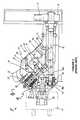
- FIG. 2A machine-tool revolving head, which is typical of the prior art and described in U.S. Pat. No. 5,146,663, is shown in FIG. 2 .
- the prior-art revolving headincorporates a fixed frame, which is fitted with a turret having multiple tool-bearing spindles.
- the arrangementincludes a driving shaft, which is connected at one end to a driving gear, and at the other end through a set of gears to the tool-bearing head of the spindle.
- the turretmoves axially and rotates with respect to the frame by means of a hydraulic driving mechanism, which includes an axial piston, a rotary piston and a chamber.
- the subject inventionprovides a reconfigurable automatic tool changer (RATC), which allows a tool cartridge to be easily attached to or detached from any standard machine-tool spindle head.
- the reconfigurable automatic tool changer (RATC)is based on a modular design, comprising a revolving-head unit, or tool cartridge, having a plurality of tool holders, a meshing gear for engaging a tool holder with the spindle of the machine tool, and an adapter block for positioning the revolving-head unit on any standard machine-tool spindle head.
- the adapter blockallows the RATC to be easily coupled to a wide variety of commercial machine-tool spindles, giving the subject invention a degree of portability not found in the prior art.
- the revolving head unit or tool cartridgealso incorporates an inventive mechanism which allows tool indexing to be achieved by means of one actuator only, in contrast to prior art-designs.
- the RATCis modular and portable, allowing the same revolving head-unit or tool cartridge to be used for various machine tool spindles. Compatibility is achieved by custom-designing the adapter block, rather than the revolving head, a task which is easier, more efficient and less costly.
- the tool holders on the revolving headare driven by the machine spindle head through a standard, off-the-shelf spur gear, which meshes with a corresponding gear on the tool holder.
- a single motor on the adapter blockdrives the revolving head unit and accomplishes the indexing function of the revolving head through a three-dimensional cam structure.
- This cam structureincludes a set of bevel gears and indexing arms spaced at a distance equal to the radius of the cam circle, in order to accommodate three to six tools in a set.
- the inventive design of the revolving-head unit or cartridge and the modularity of the entire adaptable automatic tool changer devicecreate a simpler, more efficient and portable structure which is easier to reconfigure and does not require duplication of existing equipment in a manufacturing setting.
- FIG. 1is a drawing which shows a prior-art automatic tool changer disclosed in U.S. Pat. No. 5,300,006;
- FIG. 2is a drawing which shows a prior-art automatic tool changer disclosed in FIG. 2 of U.S. Pat. No. 5,146,663;
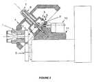
- FIG. 3is a side view of a preferred embodiment of the invention positioned on a machine-tool spindle;
- FIG. 4is an enlarged view of the revolving-head unit (tool cartridge) of the invention.
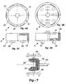
- FIG. 5 ais a plan view of an embodiment of the upper cam according to the invention.
- FIG. 5 bis a plan view of an embodiment of the lower cam according to the invention.
- FIG. 5 cis a side view of an embodiment of the upper cam according to the invention.
- FIG. 5 dis a side view of an embodiment of the lower cam according to the invention.
- FIG. 6is a plan view of the cam with the driving mechanism
- FIG. 7shows the preferred embodiment of the indexing mechanism
- FIG. 8 ais a top view of an embodiment of the adapter block
- FIG. 8 bis a side view of an embodiment of the adapter block
- FIG. 9shows the use of the invention in different types of commercial spindles
- FIG. 10 ashows a production transfer line before reconfiguration
- FIG. 10 bshows a production transfer line after reconfiguration using the invention
- FIG. 11 ashows a machine tool using the invention with a cartridge including a four-bit gang drill and a four-bit reamer;
- FIG. 11 bshows a machine tool using the invention with a cartridge including a drilling, a reaming and a tapping tool;
- FIG. 11 cshows a machine tool using the invention with a cartridge including three drill bits of different sizes
- FIGS. 12 a through 12 eshow a model of the indexing mechanism in five progressive positions a through e.
- a revolving head unit (cartridge) 4includes a set of tool heads 1 , typically three to six, and each tool head further incorporates a gear 2 .
- the revolving head unit (cartridge) 4incorporates an upper cam 5 , and a lower cam 6 with an indexing and driving mechanism 9 .
- An adapter block or unit 11is used to position the revolving head unit (cartridge) 4 on the spindle of a machine tool.
- a meshing gear 3is mounted on the machine-tool spindle and engages the selected tool head.
- a motor 10typically sits on the adapter block 11 and engages the driving mechanism of the revolving head unit (cartridge) 4 .
- the motor and meshing gearare standard units, and may be acquired separately and kept on hand for use with more than one revolving head unit, if desirable.
- the adapter block 11may be custom-made for each machine tool spindle head, if the machine tool configuration so requires, but making an adapter is a straightforward and inexpensive task.
- the revolving head unit (tool cartridge) 4is attached to the adapter block 11 by a rod 7 and spring unit 8 , which are also designed to give added rigidity to the revolving head unit (cartridge), and can be custom-made for different applications.
- the axis of the revolving head unit (cartridge) 4is at an angle, typically 45°, with the axis of the tool head
- the axis of the selected tool headis parallel to the axis of the machine-tool spindle when the meshing gear 3 and tool-head gear 2 are engaged.
- Gear 2 on the tool head and meshing gear 3 on the spindleare typically standard, off-the-self, spur gears, although it would be obvious to a person skilled in the art to replace these gears with a set of bevel gears to create alternate designs for situations requiring that the tool head axis and the axis of the spindle were not parallel.
- An additional way to accomplish the meshing of gears 2 and 3 in the event that their respective axes were not parallelwould be to adjust the angle of the inclined face of the adapter block shown in FIG. 8 .
- FIGS. 8 a and 8 bshow respectively a top view and side view of the adapter block or unit.
- the adapter unit 11has a flat bottom surface 20 designed to rest on the machine-tool spindle head.
- the top surface of the adapter unit 11has an angled section 22 on which the revolving head unit (cartridge) is positioned and, in the preferred embodiment, a flat surface 24 on which the motor driving the indexing mechanism sits.
- the adapteris typically custom-machined for a particular spindle.
- the motormay be placed directly on top of the machine-tool spindle head.
- the adapter 11is secured on the spindle head with screws or other fasteners, preferably through pre-drilled holes 26 .
- the angled surface of the adapter blockhas a pre-tapped hole 28 to receive the adapting rod 7 (in FIG. 3) connecting the revolving head unit with the adapter block.
- the adapter blockhas a slot 42 for a shaft 44 through which the driving mechanism, shown in FIG. 7, is connected with the motor.
- cutouts 21may be conveniently machined on the adapter block.
- the revolving head unit (cartridge) 4employs an inventive special three-dimensional cam structure to reduce the number of actuators needed to index the revolving head unit (cartridge).
- the cam structureincludes a circular upper cam 5 and a circular lower cam 6 as shown in FIG. 3 and in more detail in FIG. 5 .
- Plan views of the upper and lower camsare shown in FIGS. 5 a and 5 b , respectively.
- the upper camis engaged to the lower cam through pegs 23 received by holes 25 , and through lugs 29 fitting into slots 31 .
- the lugs 29 and slots 25have a cycloid profile, so that there is no interference as the upper cam lifts and rotates about its axis by means of the driving mechanism.
- FIG. 6shows the driving mechanism and the indexing mechanism.
- the indexing mechanismincludes two plates 46 , each plate having two rods or indexing arms 48 .
- the platesare connected to the bevel gears of the driving mechanism, an embodiment of which is shown in FIG. 7 .
- the revolving head unit(tool cartridge) can support six tool holders.
- the grooves 27have involute profiles so that they can engage with the straight rods 48 .
- FIG. 12illustrates the rotation and lift of the upper cam in five progressive positions, FIGS. 12 a through 12 e . At the position of FIG.
- the upper cam 5is lowered to a new position engaging with the lower cam 6 and the spring has returned to its original length.
- the plane formed by the indexing rods 90 , 91is horizontal again, but the rods have exchanged their position through a 180° rotation. When six grooves are present, a 60° rotation causes the next tool holder to be rotated in position for engagement with the spindle head.
- the distance between indexing rodscan be adjusted so that the revolving head unit (cartridge) may accommodate a different number of tool holders, in which case the angle of rotation will change accordingly.
- FIG. 9illustrates four examples of using the reconfigurable automatic tool changer with different types of commercial spindle heads.
- the adapter blockis designed in each instance to accommodate differences in the geometry of the machine tool spindle.
- FIG. 10illustrates the use of the automatic tool changer to reconfigure a production transfer line in response to changes in production volume.
- two productshave the same demand, and each go through a transfer line of three machine tools, e.g. drilling, reaming, tapping, FIG. 10 a .
- the two linescan be quickly reconfigured using the subject invention.
- the six machinesare rearranged so that one transfer line includes five dedicated machines (one drilling, two reaming and two tapping machines) for the product with increased demand.
- the other linesimply uses one machine, which is now equipped with a RATC that incorporates drilling, reaming and tapping tools, FIG. 10 b , for the product with the decreased demand.
- a RATCthat incorporates drilling, reaming and tapping tools
- FIG. 11illustrates how to accommodate frequent changes in production requirements by simply changing the tool cartridge (i.e. the revolving head unit (cartridge) of the RATC) on the adapter already sitting on the machine-tool spindle head, or by changing the set of tools in the cartridge.
- Tool cartridges housing a small number of toolsprovide an efficient way to accomplish the required reconfiguration, because they do not tie up a large number of tools in a fixed configuration that may experience repeated downtime periods, and they can be quickly replaced without the need for realignment.
- FIG. 11shows the reconfiguration of a machine tool for three different products.
- FIG. 11 ashows a cartridge having a four-bit gang drill and a four-bit reamer
- FIG. 11 bshows a cartridge including a drilling, a reaming and a tapping tool
- FIG. 11 cshows a cartridge having three drill bits of different sizes.
- indexing and driving mechanism describedrepresent the preferred embodiment, other commercially available similar means may be used to accomplish the same purpose.
- the advantage of the design of the preferred embodimentis that it only requires one actuator for the indexing motion, and it uses simple and commonly available components, such as bevel gears.
- this reconfigurable tool changeroffers the advantages of a modular design, in which the same basic resources, i.e. a revolving head unit (cartridge) with a number of tool holders, are portable and can be used in any type of spindle, by adding an adapter block and a meshing gear.
- the easily reconfigurable and modular designachieves quick assembly or disassembly of the tool cartridge from the spindle, thereby improving machine-tool utilization time and increasing productivity.
Landscapes
- Engineering & Computer Science (AREA)
- Mechanical Engineering (AREA)
- Automatic Tool Replacement In Machine Tools (AREA)
Abstract
Description
Claims (21)
Priority Applications (1)
| Application Number | Priority Date | Filing Date | Title |
|---|---|---|---|
| US09/551,668US6442815B1 (en) | 2000-04-18 | 2000-04-18 | Reconfigurable automatic tool changer |
Applications Claiming Priority (1)
| Application Number | Priority Date | Filing Date | Title |
|---|---|---|---|
| US09/551,668US6442815B1 (en) | 2000-04-18 | 2000-04-18 | Reconfigurable automatic tool changer |
Publications (1)
| Publication Number | Publication Date |
|---|---|
| US6442815B1true US6442815B1 (en) | 2002-09-03 |
Family
ID=24202203
Family Applications (1)
| Application Number | Title | Priority Date | Filing Date |
|---|---|---|---|
| US09/551,668Expired - Fee RelatedUS6442815B1 (en) | 2000-04-18 | 2000-04-18 | Reconfigurable automatic tool changer |
Country Status (1)
| Country | Link |
|---|---|
| US (1) | US6442815B1 (en) |
Cited By (10)
| Publication number | Priority date | Publication date | Assignee | Title |
|---|---|---|---|---|
| US20060127197A1 (en)* | 2003-08-11 | 2006-06-15 | Helmut Storch | Tool coupler for connecting tool heads, such as drills, reamers, millers, turn-cutters, dies, and rams, to a tool holder |
| US20070220117A1 (en)* | 2001-02-16 | 2007-09-20 | Nonend Inventions N.V. | Distribution of Streaming Content Between Media Players Configured to Locate Each Other |
| US20150059567A1 (en)* | 2011-11-30 | 2015-03-05 | Drs Sustainment Systems, Inc. | Harmonized turret with multiple gimbaled sub-systems |
| US9751173B2 (en) | 2014-09-05 | 2017-09-05 | Yamazaki Mazak Corporation | Tool magazine and tool changer |
| US20170357248A1 (en)* | 2013-12-11 | 2017-12-14 | Honda Motor Co., Ltd. | Apparatus, system and method for kitting and automation assembly |
| CN113798868A (en)* | 2021-09-06 | 2021-12-17 | 宁波海天精工股份有限公司 | Three-station automatic head warehouse |
| CN115673440A (en)* | 2022-11-08 | 2023-02-03 | 湖南省专注螺纹刀具有限公司 | Small-diameter tapping tool and machining method |
| CN117086630A (en)* | 2023-10-18 | 2023-11-21 | 云南精机琥正机械有限公司 | Vertical composite processing machine tool |
| CN117943594A (en)* | 2023-12-30 | 2024-04-30 | 江苏明微电子有限公司 | Numerical control machine tool for manufacturing semiconductor integrated circuit board |
| CN118321857A (en)* | 2023-12-15 | 2024-07-12 | 安海科技股份有限公司 | Automatic control system for disassembling waste display by utilizing automatic tool changing system |
Citations (24)
| Publication number | Priority date | Publication date | Assignee | Title |
|---|---|---|---|---|
| US3406607A (en)* | 1966-08-01 | 1968-10-22 | Walter P Hill Inc | Tool changing and feed control mechanism |
| US3604083A (en)* | 1967-07-29 | 1971-09-14 | Olivetti & Co Spa | Tool change device for a machine tool |
| US3845532A (en)* | 1971-03-17 | 1974-11-05 | Textron Inc | Turret lathe |
| JPS51124878A (en)* | 1975-04-25 | 1976-10-30 | Fanuc Ltd | Driving mechanism for turret unit |
| US4034465A (en)* | 1975-06-09 | 1977-07-12 | The Cross Company | Machining center and method of operation |
| US4090281A (en)* | 1976-11-19 | 1978-05-23 | Ameco Corporation | Machine tool with multiple tool turret |
| US4110897A (en)* | 1976-12-02 | 1978-09-05 | Bendix Machine Tool Corporation | Apparatus for automatically changing tool heads |
| US4297925A (en)* | 1978-07-15 | 1981-11-03 | Shinichi Ishizuka | Turret head for a lathe |
| US4429443A (en)* | 1979-08-24 | 1984-02-07 | Koelblin Rolf | Machine tool |
| US4656726A (en)* | 1983-12-16 | 1987-04-14 | Honda Giken Kogyo Kabushiki Kaisha | Drilling machine tool |
| US4715102A (en)* | 1986-10-31 | 1987-12-29 | The Warner & Swasey Company | Machine tool |
| JPS63120004A (en)* | 1986-11-05 | 1988-05-24 | Honda Motor Co Ltd | Turret head changing device |
| JPS6478708A (en)* | 1987-09-17 | 1989-03-24 | Honda Motor Co Ltd | Turret head replacing device |
| US4872244A (en)* | 1987-09-11 | 1989-10-10 | Index-Werke Comm.-Ges. Hahn & Tessky | Turret with several drivable tool spindles for a machine tool |
| US4922595A (en)* | 1988-09-15 | 1990-05-08 | Kira Machinery Co., Ltd. | Turret head unit |
| US5088182A (en)* | 1990-08-20 | 1992-02-18 | The Monarch Machine Tool Company | Turret changer |
| US5134767A (en)* | 1990-03-15 | 1992-08-04 | Brother Kogyo Kabushiki Kaisha | Automatic tool changing device in machine tool |
| US5146663A (en) | 1988-05-25 | 1992-09-15 | Somex Mulhouse S.A. | Revolving head for machine-tool |
| US5226869A (en)* | 1990-12-08 | 1993-07-13 | Sauter Feinmechanik Gmbh | Method and apparatus for changing the tool disk of a tool turret |
| JPH05285873A (en)* | 1992-04-07 | 1993-11-02 | Sanyo Electric Co Ltd | Turret type robot |
| US5300006A (en) | 1993-07-02 | 1994-04-05 | Okuma Machine Tools Inc. | Automatic tool changer |
| FR2704789A1 (en)* | 1993-05-07 | 1994-11-10 | Schleicher Didier | Revolving multi-spindle head for machine tool |
| US5452503A (en)* | 1993-11-15 | 1995-09-26 | Honda Giken Kogyo Kabushiki Kaisha | Turret machine tool |
| US6016729A (en)* | 1996-12-13 | 2000-01-25 | Citizen Watch Co., Ltd. | Turret device |
- 2000
- 2000-04-18USUS09/551,668patent/US6442815B1/ennot_activeExpired - Fee Related
Patent Citations (24)
| Publication number | Priority date | Publication date | Assignee | Title |
|---|---|---|---|---|
| US3406607A (en)* | 1966-08-01 | 1968-10-22 | Walter P Hill Inc | Tool changing and feed control mechanism |
| US3604083A (en)* | 1967-07-29 | 1971-09-14 | Olivetti & Co Spa | Tool change device for a machine tool |
| US3845532A (en)* | 1971-03-17 | 1974-11-05 | Textron Inc | Turret lathe |
| JPS51124878A (en)* | 1975-04-25 | 1976-10-30 | Fanuc Ltd | Driving mechanism for turret unit |
| US4034465A (en)* | 1975-06-09 | 1977-07-12 | The Cross Company | Machining center and method of operation |
| US4090281A (en)* | 1976-11-19 | 1978-05-23 | Ameco Corporation | Machine tool with multiple tool turret |
| US4110897A (en)* | 1976-12-02 | 1978-09-05 | Bendix Machine Tool Corporation | Apparatus for automatically changing tool heads |
| US4297925A (en)* | 1978-07-15 | 1981-11-03 | Shinichi Ishizuka | Turret head for a lathe |
| US4429443A (en)* | 1979-08-24 | 1984-02-07 | Koelblin Rolf | Machine tool |
| US4656726A (en)* | 1983-12-16 | 1987-04-14 | Honda Giken Kogyo Kabushiki Kaisha | Drilling machine tool |
| US4715102A (en)* | 1986-10-31 | 1987-12-29 | The Warner & Swasey Company | Machine tool |
| JPS63120004A (en)* | 1986-11-05 | 1988-05-24 | Honda Motor Co Ltd | Turret head changing device |
| US4872244A (en)* | 1987-09-11 | 1989-10-10 | Index-Werke Comm.-Ges. Hahn & Tessky | Turret with several drivable tool spindles for a machine tool |
| JPS6478708A (en)* | 1987-09-17 | 1989-03-24 | Honda Motor Co Ltd | Turret head replacing device |
| US5146663A (en) | 1988-05-25 | 1992-09-15 | Somex Mulhouse S.A. | Revolving head for machine-tool |
| US4922595A (en)* | 1988-09-15 | 1990-05-08 | Kira Machinery Co., Ltd. | Turret head unit |
| US5134767A (en)* | 1990-03-15 | 1992-08-04 | Brother Kogyo Kabushiki Kaisha | Automatic tool changing device in machine tool |
| US5088182A (en)* | 1990-08-20 | 1992-02-18 | The Monarch Machine Tool Company | Turret changer |
| US5226869A (en)* | 1990-12-08 | 1993-07-13 | Sauter Feinmechanik Gmbh | Method and apparatus for changing the tool disk of a tool turret |
| JPH05285873A (en)* | 1992-04-07 | 1993-11-02 | Sanyo Electric Co Ltd | Turret type robot |
| FR2704789A1 (en)* | 1993-05-07 | 1994-11-10 | Schleicher Didier | Revolving multi-spindle head for machine tool |
| US5300006A (en) | 1993-07-02 | 1994-04-05 | Okuma Machine Tools Inc. | Automatic tool changer |
| US5452503A (en)* | 1993-11-15 | 1995-09-26 | Honda Giken Kogyo Kabushiki Kaisha | Turret machine tool |
| US6016729A (en)* | 1996-12-13 | 2000-01-25 | Citizen Watch Co., Ltd. | Turret device |
Cited By (17)
| Publication number | Priority date | Publication date | Assignee | Title |
|---|---|---|---|---|
| US20070220117A1 (en)* | 2001-02-16 | 2007-09-20 | Nonend Inventions N.V. | Distribution of Streaming Content Between Media Players Configured to Locate Each Other |
| US20060127197A1 (en)* | 2003-08-11 | 2006-06-15 | Helmut Storch | Tool coupler for connecting tool heads, such as drills, reamers, millers, turn-cutters, dies, and rams, to a tool holder |
| US7338419B2 (en)* | 2003-08-11 | 2008-03-04 | Kennametal Inc. | Tool coupler for connecting tool heads, such as drills, reamers, millers, turn-cutters, dies, and rams, to a tool holder |
| US20150059567A1 (en)* | 2011-11-30 | 2015-03-05 | Drs Sustainment Systems, Inc. | Harmonized turret with multiple gimbaled sub-systems |
| US9032859B2 (en)* | 2011-11-30 | 2015-05-19 | Drs Sustainment Systems, Inc. | Harmonized turret with multiple gimbaled sub-systems |
| US9121670B2 (en) | 2011-11-30 | 2015-09-01 | Drs Sustainment Systems, Inc. | Operational control logic for harmonized turret with gimbaled sub-systems |
| US9523548B2 (en) | 2011-11-30 | 2016-12-20 | Drs Sustainment Systems, Inc. | Operational control logic for harmonized turret with gimbaled sub-systems |
| US20170357248A1 (en)* | 2013-12-11 | 2017-12-14 | Honda Motor Co., Ltd. | Apparatus, system and method for kitting and automation assembly |
| US10520926B2 (en)* | 2013-12-11 | 2019-12-31 | Honda Motor Co., Ltd. | Apparatus, system and method for kitting and automation assembly |
| US9751173B2 (en) | 2014-09-05 | 2017-09-05 | Yamazaki Mazak Corporation | Tool magazine and tool changer |
| CN113798868A (en)* | 2021-09-06 | 2021-12-17 | 宁波海天精工股份有限公司 | Three-station automatic head warehouse |
| CN113798868B (en)* | 2021-09-06 | 2022-10-14 | 宁波海天精工股份有限公司 | Three-station automatic head warehouse |
| CN115673440A (en)* | 2022-11-08 | 2023-02-03 | 湖南省专注螺纹刀具有限公司 | Small-diameter tapping tool and machining method |
| CN117086630A (en)* | 2023-10-18 | 2023-11-21 | 云南精机琥正机械有限公司 | Vertical composite processing machine tool |
| CN117086630B (en)* | 2023-10-18 | 2023-12-15 | 云南精机琥正机械有限公司 | Vertical composite processing machine tool |
| CN118321857A (en)* | 2023-12-15 | 2024-07-12 | 安海科技股份有限公司 | Automatic control system for disassembling waste display by utilizing automatic tool changing system |
| CN117943594A (en)* | 2023-12-30 | 2024-04-30 | 江苏明微电子有限公司 | Numerical control machine tool for manufacturing semiconductor integrated circuit board |
Similar Documents
| Publication | Publication Date | Title |
|---|---|---|
| US6442815B1 (en) | Reconfigurable automatic tool changer | |
| CN112318121B (en) | Multi-station special machine and machining method thereof | |
| US5300006A (en) | Automatic tool changer | |
| US4090281A (en) | Machine tool with multiple tool turret | |
| US4478540A (en) | Spindle head assembly with oblique axis of rotation | |
| US6553656B1 (en) | Assembly or manufacturing robot and work station for the same | |
| KR20190083092A (en) | Tool turret of machine tool | |
| KR20160109000A (en) | Turret tool post and tool machine having the same | |
| KR101724056B1 (en) | Automatic tool changer having single driven dual tool magazine type | |
| CN213795437U (en) | Turning and milling composite tool magazine | |
| US4622734A (en) | Apparatus for the variable machining of workpieces | |
| US20050091812A1 (en) | Machining center | |
| CN212552706U (en) | Five-axis multi-angle CNC turntable | |
| US5016334A (en) | Multiple spindle bar machine | |
| CN219598696U (en) | Gantry machining center with high stability | |
| CN209954285U (en) | Multifunctional rotary machining shaft with rapid clamping function | |
| US3949462A (en) | Removable attachment for automating milling machines | |
| US3951273A (en) | Removable attachment for automating milling machines | |
| CN217965794U (en) | Single-power-tool tower type turning and milling composite numerical control machine | |
| CN212762113U (en) | Thrust gear main bearing cap rotary disc type processing machine tool | |
| CN216227905U (en) | Numerical control machining center capable of changing tools quickly | |
| CN214080133U (en) | Differential mechanism tightening machine | |
| CN114102145A (en) | A profile four-sided drilling and milling processing device | |
| CN220516052U (en) | Frock is used in vertical machining center of four-axis | |
| CN220463038U (en) | Straight bed body linear rail digit control machine tool |
Legal Events
| Date | Code | Title | Description |
|---|---|---|---|
| AS | Assignment | Owner name:REGENTS OF THE UNIVERSITY OF MICHIGAN, THE, MICHIG Free format text:ASSIGNMENT OF ASSIGNORS INTEREST;ASSIGNORS:MOON, YONG-MO;KOKTA, SRIDHAR;REEL/FRAME:010734/0706 Effective date:20000323 | |
| AS | Assignment | Owner name:NATIONAL SCIENCE FOUNDATION, VIRGINIA Free format text:CONFIRMATORY LICENSE;ASSIGNOR:UNIVERSITY OF MICHIGAN;REEL/FRAME:013445/0530 Effective date:20000516 | |
| FPAY | Fee payment | Year of fee payment:4 | |
| FPAY | Fee payment | Year of fee payment:8 | |
| REMI | Maintenance fee reminder mailed | ||
| LAPS | Lapse for failure to pay maintenance fees | ||
| STCH | Information on status: patent discontinuation | Free format text:PATENT EXPIRED DUE TO NONPAYMENT OF MAINTENANCE FEES UNDER 37 CFR 1.362 | |
| FP | Expired due to failure to pay maintenance fee | Effective date:20140903 | |
| AS | Assignment | Owner name:NATIONAL SCIENCE FOUNDATION, VIRGINIA Free format text:CONFIRMATORY LICENSE;ASSIGNOR:UNIVERSITY OF MICHIGAN;REEL/FRAME:047538/0273 Effective date:20181031 | |
| AS | Assignment | Owner name:NATIONAL SCIENCE FOUNDATION, VIRGINIA Free format text:CONFIRMATORY LICENSE;ASSIGNOR:UNIVERSITY OF MICHIGAN;REEL/FRAME:048286/0497 Effective date:20190130 |