US6442814B1 - Apparatus for manufacturing a bone dowel - Google Patents
Apparatus for manufacturing a bone dowelDownload PDFInfo
- Publication number
- US6442814B1 US6442814B1US09/298,269US29826999AUS6442814B1US 6442814 B1US6442814 B1US 6442814B1US 29826999 AUS29826999 AUS 29826999AUS 6442814 B1US6442814 B1US 6442814B1
- Authority
- US
- United States
- Prior art keywords
- module
- track
- dowel
- cutting tool
- collet
- Prior art date
- Legal status (The legal status is an assumption and is not a legal conclusion. Google has not performed a legal analysis and makes no representation as to the accuracy of the status listed.)
- Expired - Fee Related
Links
Images


Classifications
- A—HUMAN NECESSITIES
- A61—MEDICAL OR VETERINARY SCIENCE; HYGIENE
- A61F—FILTERS IMPLANTABLE INTO BLOOD VESSELS; PROSTHESES; DEVICES PROVIDING PATENCY TO, OR PREVENTING COLLAPSING OF, TUBULAR STRUCTURES OF THE BODY, e.g. STENTS; ORTHOPAEDIC, NURSING OR CONTRACEPTIVE DEVICES; FOMENTATION; TREATMENT OR PROTECTION OF EYES OR EARS; BANDAGES, DRESSINGS OR ABSORBENT PADS; FIRST-AID KITS
- A61F2/00—Filters implantable into blood vessels; Prostheses, i.e. artificial substitutes or replacements for parts of the body; Appliances for connecting them with the body; Devices providing patency to, or preventing collapsing of, tubular structures of the body, e.g. stents
- A61F2/02—Prostheses implantable into the body
- A61F2/30—Joints
- A61F2/46—Special tools for implanting artificial joints
- A61F2/4644—Preparation of bone graft, bone plugs or bone dowels, e.g. grinding or milling bone material
- A—HUMAN NECESSITIES
- A61—MEDICAL OR VETERINARY SCIENCE; HYGIENE
- A61F—FILTERS IMPLANTABLE INTO BLOOD VESSELS; PROSTHESES; DEVICES PROVIDING PATENCY TO, OR PREVENTING COLLAPSING OF, TUBULAR STRUCTURES OF THE BODY, e.g. STENTS; ORTHOPAEDIC, NURSING OR CONTRACEPTIVE DEVICES; FOMENTATION; TREATMENT OR PROTECTION OF EYES OR EARS; BANDAGES, DRESSINGS OR ABSORBENT PADS; FIRST-AID KITS
- A61F2/00—Filters implantable into blood vessels; Prostheses, i.e. artificial substitutes or replacements for parts of the body; Appliances for connecting them with the body; Devices providing patency to, or preventing collapsing of, tubular structures of the body, e.g. stents
- A61F2/02—Prostheses implantable into the body
- A61F2/28—Bones
- B—PERFORMING OPERATIONS; TRANSPORTING
- B23—MACHINE TOOLS; METAL-WORKING NOT OTHERWISE PROVIDED FOR
- B23Q—DETAILS, COMPONENTS, OR ACCESSORIES FOR MACHINE TOOLS, e.g. ARRANGEMENTS FOR COPYING OR CONTROLLING; MACHINE TOOLS IN GENERAL CHARACTERISED BY THE CONSTRUCTION OF PARTICULAR DETAILS OR COMPONENTS; COMBINATIONS OR ASSOCIATIONS OF METAL-WORKING MACHINES, NOT DIRECTED TO A PARTICULAR RESULT
- B23Q1/00—Members which are comprised in the general build-up of a form of machine, particularly relatively large fixed members
- B23Q1/25—Movable or adjustable work or tool supports
- B23Q1/44—Movable or adjustable work or tool supports using particular mechanisms
- B23Q1/56—Movable or adjustable work or tool supports using particular mechanisms with sliding pairs only, the sliding pairs being the first two elements of the mechanism
- B23Q1/60—Movable or adjustable work or tool supports using particular mechanisms with sliding pairs only, the sliding pairs being the first two elements of the mechanism two sliding pairs only, the sliding pairs being the first two elements of the mechanism
- B23Q1/62—Movable or adjustable work or tool supports using particular mechanisms with sliding pairs only, the sliding pairs being the first two elements of the mechanism two sliding pairs only, the sliding pairs being the first two elements of the mechanism with perpendicular axes, e.g. cross-slides
- B23Q1/621—Movable or adjustable work or tool supports using particular mechanisms with sliding pairs only, the sliding pairs being the first two elements of the mechanism two sliding pairs only, the sliding pairs being the first two elements of the mechanism with perpendicular axes, e.g. cross-slides a single sliding pair followed perpendicularly by a single sliding pair
- A—HUMAN NECESSITIES
- A61—MEDICAL OR VETERINARY SCIENCE; HYGIENE
- A61F—FILTERS IMPLANTABLE INTO BLOOD VESSELS; PROSTHESES; DEVICES PROVIDING PATENCY TO, OR PREVENTING COLLAPSING OF, TUBULAR STRUCTURES OF THE BODY, e.g. STENTS; ORTHOPAEDIC, NURSING OR CONTRACEPTIVE DEVICES; FOMENTATION; TREATMENT OR PROTECTION OF EYES OR EARS; BANDAGES, DRESSINGS OR ABSORBENT PADS; FIRST-AID KITS
- A61F2/00—Filters implantable into blood vessels; Prostheses, i.e. artificial substitutes or replacements for parts of the body; Appliances for connecting them with the body; Devices providing patency to, or preventing collapsing of, tubular structures of the body, e.g. stents
- A61F2/02—Prostheses implantable into the body
- A61F2/30—Joints
- A61F2/3094—Designing or manufacturing processes
- A—HUMAN NECESSITIES
- A61—MEDICAL OR VETERINARY SCIENCE; HYGIENE
- A61F—FILTERS IMPLANTABLE INTO BLOOD VESSELS; PROSTHESES; DEVICES PROVIDING PATENCY TO, OR PREVENTING COLLAPSING OF, TUBULAR STRUCTURES OF THE BODY, e.g. STENTS; ORTHOPAEDIC, NURSING OR CONTRACEPTIVE DEVICES; FOMENTATION; TREATMENT OR PROTECTION OF EYES OR EARS; BANDAGES, DRESSINGS OR ABSORBENT PADS; FIRST-AID KITS
- A61F2/00—Filters implantable into blood vessels; Prostheses, i.e. artificial substitutes or replacements for parts of the body; Appliances for connecting them with the body; Devices providing patency to, or preventing collapsing of, tubular structures of the body, e.g. stents
- A61F2/02—Prostheses implantable into the body
- A61F2/28—Bones
- A61F2002/2835—Bone graft implants for filling a bony defect or an endoprosthesis cavity, e.g. by synthetic material or biological material
- A61F2002/2839—Bone plugs or bone graft dowels
- A—HUMAN NECESSITIES
- A61—MEDICAL OR VETERINARY SCIENCE; HYGIENE
- A61F—FILTERS IMPLANTABLE INTO BLOOD VESSELS; PROSTHESES; DEVICES PROVIDING PATENCY TO, OR PREVENTING COLLAPSING OF, TUBULAR STRUCTURES OF THE BODY, e.g. STENTS; ORTHOPAEDIC, NURSING OR CONTRACEPTIVE DEVICES; FOMENTATION; TREATMENT OR PROTECTION OF EYES OR EARS; BANDAGES, DRESSINGS OR ABSORBENT PADS; FIRST-AID KITS
- A61F2/00—Filters implantable into blood vessels; Prostheses, i.e. artificial substitutes or replacements for parts of the body; Appliances for connecting them with the body; Devices providing patency to, or preventing collapsing of, tubular structures of the body, e.g. stents
- A61F2/02—Prostheses implantable into the body
- A61F2/30—Joints
- A61F2002/30001—Additional features of subject-matter classified in A61F2/28, A61F2/30 and subgroups thereof
- A61F2002/30108—Shapes
- A61F2002/3011—Cross-sections or two-dimensional shapes
- A61F2002/30112—Rounded shapes, e.g. with rounded corners
- A61F2002/30125—Rounded shapes, e.g. with rounded corners elliptical or oval
- A—HUMAN NECESSITIES
- A61—MEDICAL OR VETERINARY SCIENCE; HYGIENE
- A61F—FILTERS IMPLANTABLE INTO BLOOD VESSELS; PROSTHESES; DEVICES PROVIDING PATENCY TO, OR PREVENTING COLLAPSING OF, TUBULAR STRUCTURES OF THE BODY, e.g. STENTS; ORTHOPAEDIC, NURSING OR CONTRACEPTIVE DEVICES; FOMENTATION; TREATMENT OR PROTECTION OF EYES OR EARS; BANDAGES, DRESSINGS OR ABSORBENT PADS; FIRST-AID KITS
- A61F2/00—Filters implantable into blood vessels; Prostheses, i.e. artificial substitutes or replacements for parts of the body; Appliances for connecting them with the body; Devices providing patency to, or preventing collapsing of, tubular structures of the body, e.g. stents
- A61F2/02—Prostheses implantable into the body
- A61F2/30—Joints
- A61F2002/30001—Additional features of subject-matter classified in A61F2/28, A61F2/30 and subgroups thereof
- A61F2002/30108—Shapes
- A61F2002/3011—Cross-sections or two-dimensional shapes
- A61F2002/30138—Convex polygonal shapes
- A61F2002/30143—Convex polygonal shapes hexagonal
- A—HUMAN NECESSITIES
- A61—MEDICAL OR VETERINARY SCIENCE; HYGIENE
- A61F—FILTERS IMPLANTABLE INTO BLOOD VESSELS; PROSTHESES; DEVICES PROVIDING PATENCY TO, OR PREVENTING COLLAPSING OF, TUBULAR STRUCTURES OF THE BODY, e.g. STENTS; ORTHOPAEDIC, NURSING OR CONTRACEPTIVE DEVICES; FOMENTATION; TREATMENT OR PROTECTION OF EYES OR EARS; BANDAGES, DRESSINGS OR ABSORBENT PADS; FIRST-AID KITS
- A61F2/00—Filters implantable into blood vessels; Prostheses, i.e. artificial substitutes or replacements for parts of the body; Appliances for connecting them with the body; Devices providing patency to, or preventing collapsing of, tubular structures of the body, e.g. stents
- A61F2/02—Prostheses implantable into the body
- A61F2/30—Joints
- A61F2002/30001—Additional features of subject-matter classified in A61F2/28, A61F2/30 and subgroups thereof
- A61F2002/30108—Shapes
- A61F2002/3011—Cross-sections or two-dimensional shapes
- A61F2002/30159—Concave polygonal shapes
- A61F2002/30179—X-shaped
- A—HUMAN NECESSITIES
- A61—MEDICAL OR VETERINARY SCIENCE; HYGIENE
- A61F—FILTERS IMPLANTABLE INTO BLOOD VESSELS; PROSTHESES; DEVICES PROVIDING PATENCY TO, OR PREVENTING COLLAPSING OF, TUBULAR STRUCTURES OF THE BODY, e.g. STENTS; ORTHOPAEDIC, NURSING OR CONTRACEPTIVE DEVICES; FOMENTATION; TREATMENT OR PROTECTION OF EYES OR EARS; BANDAGES, DRESSINGS OR ABSORBENT PADS; FIRST-AID KITS
- A61F2/00—Filters implantable into blood vessels; Prostheses, i.e. artificial substitutes or replacements for parts of the body; Appliances for connecting them with the body; Devices providing patency to, or preventing collapsing of, tubular structures of the body, e.g. stents
- A61F2/02—Prostheses implantable into the body
- A61F2/30—Joints
- A61F2002/30001—Additional features of subject-matter classified in A61F2/28, A61F2/30 and subgroups thereof
- A61F2002/30108—Shapes
- A61F2002/30199—Three-dimensional shapes
- A61F2002/30224—Three-dimensional shapes cylindrical
- A—HUMAN NECESSITIES
- A61—MEDICAL OR VETERINARY SCIENCE; HYGIENE
- A61F—FILTERS IMPLANTABLE INTO BLOOD VESSELS; PROSTHESES; DEVICES PROVIDING PATENCY TO, OR PREVENTING COLLAPSING OF, TUBULAR STRUCTURES OF THE BODY, e.g. STENTS; ORTHOPAEDIC, NURSING OR CONTRACEPTIVE DEVICES; FOMENTATION; TREATMENT OR PROTECTION OF EYES OR EARS; BANDAGES, DRESSINGS OR ABSORBENT PADS; FIRST-AID KITS
- A61F2/00—Filters implantable into blood vessels; Prostheses, i.e. artificial substitutes or replacements for parts of the body; Appliances for connecting them with the body; Devices providing patency to, or preventing collapsing of, tubular structures of the body, e.g. stents
- A61F2/02—Prostheses implantable into the body
- A61F2/30—Joints
- A61F2/30767—Special external or bone-contacting surface, e.g. coating for improving bone ingrowth
- A61F2/30771—Special external or bone-contacting surface, e.g. coating for improving bone ingrowth applied in original prostheses, e.g. holes or grooves
- A61F2002/30772—Apertures or holes, e.g. of circular cross section
- A61F2002/30774—Apertures or holes, e.g. of circular cross section internally-threaded
- A—HUMAN NECESSITIES
- A61—MEDICAL OR VETERINARY SCIENCE; HYGIENE
- A61F—FILTERS IMPLANTABLE INTO BLOOD VESSELS; PROSTHESES; DEVICES PROVIDING PATENCY TO, OR PREVENTING COLLAPSING OF, TUBULAR STRUCTURES OF THE BODY, e.g. STENTS; ORTHOPAEDIC, NURSING OR CONTRACEPTIVE DEVICES; FOMENTATION; TREATMENT OR PROTECTION OF EYES OR EARS; BANDAGES, DRESSINGS OR ABSORBENT PADS; FIRST-AID KITS
- A61F2/00—Filters implantable into blood vessels; Prostheses, i.e. artificial substitutes or replacements for parts of the body; Appliances for connecting them with the body; Devices providing patency to, or preventing collapsing of, tubular structures of the body, e.g. stents
- A61F2/02—Prostheses implantable into the body
- A61F2/30—Joints
- A61F2/30767—Special external or bone-contacting surface, e.g. coating for improving bone ingrowth
- A61F2/30771—Special external or bone-contacting surface, e.g. coating for improving bone ingrowth applied in original prostheses, e.g. holes or grooves
- A61F2002/30772—Apertures or holes, e.g. of circular cross section
- A61F2002/30777—Oblong apertures
- A—HUMAN NECESSITIES
- A61—MEDICAL OR VETERINARY SCIENCE; HYGIENE
- A61F—FILTERS IMPLANTABLE INTO BLOOD VESSELS; PROSTHESES; DEVICES PROVIDING PATENCY TO, OR PREVENTING COLLAPSING OF, TUBULAR STRUCTURES OF THE BODY, e.g. STENTS; ORTHOPAEDIC, NURSING OR CONTRACEPTIVE DEVICES; FOMENTATION; TREATMENT OR PROTECTION OF EYES OR EARS; BANDAGES, DRESSINGS OR ABSORBENT PADS; FIRST-AID KITS
- A61F2/00—Filters implantable into blood vessels; Prostheses, i.e. artificial substitutes or replacements for parts of the body; Appliances for connecting them with the body; Devices providing patency to, or preventing collapsing of, tubular structures of the body, e.g. stents
- A61F2/02—Prostheses implantable into the body
- A61F2/30—Joints
- A61F2/30767—Special external or bone-contacting surface, e.g. coating for improving bone ingrowth
- A61F2/30771—Special external or bone-contacting surface, e.g. coating for improving bone ingrowth applied in original prostheses, e.g. holes or grooves
- A61F2002/30772—Apertures or holes, e.g. of circular cross section
- A61F2002/30784—Plurality of holes
- A61F2002/30789—Plurality of holes perpendicular with respect to each other
- A—HUMAN NECESSITIES
- A61—MEDICAL OR VETERINARY SCIENCE; HYGIENE
- A61F—FILTERS IMPLANTABLE INTO BLOOD VESSELS; PROSTHESES; DEVICES PROVIDING PATENCY TO, OR PREVENTING COLLAPSING OF, TUBULAR STRUCTURES OF THE BODY, e.g. STENTS; ORTHOPAEDIC, NURSING OR CONTRACEPTIVE DEVICES; FOMENTATION; TREATMENT OR PROTECTION OF EYES OR EARS; BANDAGES, DRESSINGS OR ABSORBENT PADS; FIRST-AID KITS
- A61F2/00—Filters implantable into blood vessels; Prostheses, i.e. artificial substitutes or replacements for parts of the body; Appliances for connecting them with the body; Devices providing patency to, or preventing collapsing of, tubular structures of the body, e.g. stents
- A61F2/02—Prostheses implantable into the body
- A61F2/30—Joints
- A61F2/30767—Special external or bone-contacting surface, e.g. coating for improving bone ingrowth
- A61F2/30771—Special external or bone-contacting surface, e.g. coating for improving bone ingrowth applied in original prostheses, e.g. holes or grooves
- A61F2002/30795—Blind bores, e.g. of circular cross-section
- A61F2002/308—Blind bores, e.g. of circular cross-section oblong
- A—HUMAN NECESSITIES
- A61—MEDICAL OR VETERINARY SCIENCE; HYGIENE
- A61F—FILTERS IMPLANTABLE INTO BLOOD VESSELS; PROSTHESES; DEVICES PROVIDING PATENCY TO, OR PREVENTING COLLAPSING OF, TUBULAR STRUCTURES OF THE BODY, e.g. STENTS; ORTHOPAEDIC, NURSING OR CONTRACEPTIVE DEVICES; FOMENTATION; TREATMENT OR PROTECTION OF EYES OR EARS; BANDAGES, DRESSINGS OR ABSORBENT PADS; FIRST-AID KITS
- A61F2/00—Filters implantable into blood vessels; Prostheses, i.e. artificial substitutes or replacements for parts of the body; Appliances for connecting them with the body; Devices providing patency to, or preventing collapsing of, tubular structures of the body, e.g. stents
- A61F2/02—Prostheses implantable into the body
- A61F2/30—Joints
- A61F2/30767—Special external or bone-contacting surface, e.g. coating for improving bone ingrowth
- A61F2/30771—Special external or bone-contacting surface, e.g. coating for improving bone ingrowth applied in original prostheses, e.g. holes or grooves
- A61F2002/30795—Blind bores, e.g. of circular cross-section
- A61F2002/30805—Recesses of comparatively large area with respect to their low depth
- A—HUMAN NECESSITIES
- A61—MEDICAL OR VETERINARY SCIENCE; HYGIENE
- A61F—FILTERS IMPLANTABLE INTO BLOOD VESSELS; PROSTHESES; DEVICES PROVIDING PATENCY TO, OR PREVENTING COLLAPSING OF, TUBULAR STRUCTURES OF THE BODY, e.g. STENTS; ORTHOPAEDIC, NURSING OR CONTRACEPTIVE DEVICES; FOMENTATION; TREATMENT OR PROTECTION OF EYES OR EARS; BANDAGES, DRESSINGS OR ABSORBENT PADS; FIRST-AID KITS
- A61F2/00—Filters implantable into blood vessels; Prostheses, i.e. artificial substitutes or replacements for parts of the body; Appliances for connecting them with the body; Devices providing patency to, or preventing collapsing of, tubular structures of the body, e.g. stents
- A61F2/02—Prostheses implantable into the body
- A61F2/30—Joints
- A61F2/30767—Special external or bone-contacting surface, e.g. coating for improving bone ingrowth
- A61F2/30771—Special external or bone-contacting surface, e.g. coating for improving bone ingrowth applied in original prostheses, e.g. holes or grooves
- A61F2002/3082—Grooves
- A—HUMAN NECESSITIES
- A61—MEDICAL OR VETERINARY SCIENCE; HYGIENE
- A61F—FILTERS IMPLANTABLE INTO BLOOD VESSELS; PROSTHESES; DEVICES PROVIDING PATENCY TO, OR PREVENTING COLLAPSING OF, TUBULAR STRUCTURES OF THE BODY, e.g. STENTS; ORTHOPAEDIC, NURSING OR CONTRACEPTIVE DEVICES; FOMENTATION; TREATMENT OR PROTECTION OF EYES OR EARS; BANDAGES, DRESSINGS OR ABSORBENT PADS; FIRST-AID KITS
- A61F2/00—Filters implantable into blood vessels; Prostheses, i.e. artificial substitutes or replacements for parts of the body; Appliances for connecting them with the body; Devices providing patency to, or preventing collapsing of, tubular structures of the body, e.g. stents
- A61F2/02—Prostheses implantable into the body
- A61F2/30—Joints
- A61F2/30767—Special external or bone-contacting surface, e.g. coating for improving bone ingrowth
- A61F2/30771—Special external or bone-contacting surface, e.g. coating for improving bone ingrowth applied in original prostheses, e.g. holes or grooves
- A61F2002/3085—Special external or bone-contacting surface, e.g. coating for improving bone ingrowth applied in original prostheses, e.g. holes or grooves with a threaded, e.g. self-tapping, bone-engaging surface, e.g. external surface
- A61F2002/30868—Square, rectangular or rhomboidal threads
- A—HUMAN NECESSITIES
- A61—MEDICAL OR VETERINARY SCIENCE; HYGIENE
- A61F—FILTERS IMPLANTABLE INTO BLOOD VESSELS; PROSTHESES; DEVICES PROVIDING PATENCY TO, OR PREVENTING COLLAPSING OF, TUBULAR STRUCTURES OF THE BODY, e.g. STENTS; ORTHOPAEDIC, NURSING OR CONTRACEPTIVE DEVICES; FOMENTATION; TREATMENT OR PROTECTION OF EYES OR EARS; BANDAGES, DRESSINGS OR ABSORBENT PADS; FIRST-AID KITS
- A61F2/00—Filters implantable into blood vessels; Prostheses, i.e. artificial substitutes or replacements for parts of the body; Appliances for connecting them with the body; Devices providing patency to, or preventing collapsing of, tubular structures of the body, e.g. stents
- A61F2/02—Prostheses implantable into the body
- A61F2/30—Joints
- A61F2/30767—Special external or bone-contacting surface, e.g. coating for improving bone ingrowth
- A61F2/30771—Special external or bone-contacting surface, e.g. coating for improving bone ingrowth applied in original prostheses, e.g. holes or grooves
- A61F2002/3085—Special external or bone-contacting surface, e.g. coating for improving bone ingrowth applied in original prostheses, e.g. holes or grooves with a threaded, e.g. self-tapping, bone-engaging surface, e.g. external surface
- A61F2002/30871—Trapezoidal threads
- A—HUMAN NECESSITIES
- A61—MEDICAL OR VETERINARY SCIENCE; HYGIENE
- A61F—FILTERS IMPLANTABLE INTO BLOOD VESSELS; PROSTHESES; DEVICES PROVIDING PATENCY TO, OR PREVENTING COLLAPSING OF, TUBULAR STRUCTURES OF THE BODY, e.g. STENTS; ORTHOPAEDIC, NURSING OR CONTRACEPTIVE DEVICES; FOMENTATION; TREATMENT OR PROTECTION OF EYES OR EARS; BANDAGES, DRESSINGS OR ABSORBENT PADS; FIRST-AID KITS
- A61F2230/00—Geometry of prostheses classified in groups A61F2/00 - A61F2/26 or A61F2/82 or A61F9/00 or A61F11/00 or subgroups thereof
- A61F2230/0002—Two-dimensional shapes, e.g. cross-sections
- A61F2230/0004—Rounded shapes, e.g. with rounded corners
- A61F2230/0008—Rounded shapes, e.g. with rounded corners elliptical or oval
- A—HUMAN NECESSITIES
- A61—MEDICAL OR VETERINARY SCIENCE; HYGIENE
- A61F—FILTERS IMPLANTABLE INTO BLOOD VESSELS; PROSTHESES; DEVICES PROVIDING PATENCY TO, OR PREVENTING COLLAPSING OF, TUBULAR STRUCTURES OF THE BODY, e.g. STENTS; ORTHOPAEDIC, NURSING OR CONTRACEPTIVE DEVICES; FOMENTATION; TREATMENT OR PROTECTION OF EYES OR EARS; BANDAGES, DRESSINGS OR ABSORBENT PADS; FIRST-AID KITS
- A61F2230/00—Geometry of prostheses classified in groups A61F2/00 - A61F2/26 or A61F2/82 or A61F9/00 or A61F11/00 or subgroups thereof
- A61F2230/0002—Two-dimensional shapes, e.g. cross-sections
- A61F2230/0017—Angular shapes
- A—HUMAN NECESSITIES
- A61—MEDICAL OR VETERINARY SCIENCE; HYGIENE
- A61F—FILTERS IMPLANTABLE INTO BLOOD VESSELS; PROSTHESES; DEVICES PROVIDING PATENCY TO, OR PREVENTING COLLAPSING OF, TUBULAR STRUCTURES OF THE BODY, e.g. STENTS; ORTHOPAEDIC, NURSING OR CONTRACEPTIVE DEVICES; FOMENTATION; TREATMENT OR PROTECTION OF EYES OR EARS; BANDAGES, DRESSINGS OR ABSORBENT PADS; FIRST-AID KITS
- A61F2230/00—Geometry of prostheses classified in groups A61F2/00 - A61F2/26 or A61F2/82 or A61F9/00 or A61F11/00 or subgroups thereof
- A61F2230/0002—Two-dimensional shapes, e.g. cross-sections
- A61F2230/0028—Shapes in the form of latin or greek characters
- A61F2230/0058—X-shaped
- A—HUMAN NECESSITIES
- A61—MEDICAL OR VETERINARY SCIENCE; HYGIENE
- A61F—FILTERS IMPLANTABLE INTO BLOOD VESSELS; PROSTHESES; DEVICES PROVIDING PATENCY TO, OR PREVENTING COLLAPSING OF, TUBULAR STRUCTURES OF THE BODY, e.g. STENTS; ORTHOPAEDIC, NURSING OR CONTRACEPTIVE DEVICES; FOMENTATION; TREATMENT OR PROTECTION OF EYES OR EARS; BANDAGES, DRESSINGS OR ABSORBENT PADS; FIRST-AID KITS
- A61F2230/00—Geometry of prostheses classified in groups A61F2/00 - A61F2/26 or A61F2/82 or A61F9/00 or A61F11/00 or subgroups thereof
- A61F2230/0063—Three-dimensional shapes
- A61F2230/0069—Three-dimensional shapes cylindrical
- Y—GENERAL TAGGING OF NEW TECHNOLOGICAL DEVELOPMENTS; GENERAL TAGGING OF CROSS-SECTIONAL TECHNOLOGIES SPANNING OVER SEVERAL SECTIONS OF THE IPC; TECHNICAL SUBJECTS COVERED BY FORMER USPC CROSS-REFERENCE ART COLLECTIONS [XRACs] AND DIGESTS
- Y10—TECHNICAL SUBJECTS COVERED BY FORMER USPC
- Y10T—TECHNICAL SUBJECTS COVERED BY FORMER US CLASSIFICATION
- Y10T29/00—Metal working
- Y10T29/51—Plural diverse manufacturing apparatus including means for metal shaping or assembling
- Y10T29/5104—Type of machine
- Y10T29/5105—Drill press
- Y10T29/5108—Portable
- Y—GENERAL TAGGING OF NEW TECHNOLOGICAL DEVELOPMENTS; GENERAL TAGGING OF CROSS-SECTIONAL TECHNOLOGIES SPANNING OVER SEVERAL SECTIONS OF THE IPC; TECHNICAL SUBJECTS COVERED BY FORMER USPC CROSS-REFERENCE ART COLLECTIONS [XRACs] AND DIGESTS
- Y10—TECHNICAL SUBJECTS COVERED BY FORMER USPC
- Y10T—TECHNICAL SUBJECTS COVERED BY FORMER US CLASSIFICATION
- Y10T29/00—Metal working
- Y10T29/51—Plural diverse manufacturing apparatus including means for metal shaping or assembling
- Y10T29/5104—Type of machine
- Y10T29/5109—Lathe
- Y10T29/5112—Convertible
- Y—GENERAL TAGGING OF NEW TECHNOLOGICAL DEVELOPMENTS; GENERAL TAGGING OF CROSS-SECTIONAL TECHNOLOGIES SPANNING OVER SEVERAL SECTIONS OF THE IPC; TECHNICAL SUBJECTS COVERED BY FORMER USPC CROSS-REFERENCE ART COLLECTIONS [XRACs] AND DIGESTS
- Y10—TECHNICAL SUBJECTS COVERED BY FORMER USPC
- Y10T—TECHNICAL SUBJECTS COVERED BY FORMER US CLASSIFICATION
- Y10T408/00—Cutting by use of rotating axially moving tool
- Y10T408/31—Convertible cutting means
- Y—GENERAL TAGGING OF NEW TECHNOLOGICAL DEVELOPMENTS; GENERAL TAGGING OF CROSS-SECTIONAL TECHNOLOGIES SPANNING OVER SEVERAL SECTIONS OF THE IPC; TECHNICAL SUBJECTS COVERED BY FORMER USPC CROSS-REFERENCE ART COLLECTIONS [XRACs] AND DIGESTS
- Y10—TECHNICAL SUBJECTS COVERED BY FORMER USPC
- Y10T—TECHNICAL SUBJECTS COVERED BY FORMER US CLASSIFICATION
- Y10T408/00—Cutting by use of rotating axially moving tool
- Y10T408/47—Cutting by use of rotating axially moving tool with work-infeed means
- Y—GENERAL TAGGING OF NEW TECHNOLOGICAL DEVELOPMENTS; GENERAL TAGGING OF CROSS-SECTIONAL TECHNOLOGIES SPANNING OVER SEVERAL SECTIONS OF THE IPC; TECHNICAL SUBJECTS COVERED BY FORMER USPC CROSS-REFERENCE ART COLLECTIONS [XRACs] AND DIGESTS
- Y10—TECHNICAL SUBJECTS COVERED BY FORMER USPC
- Y10T—TECHNICAL SUBJECTS COVERED BY FORMER US CLASSIFICATION
- Y10T408/00—Cutting by use of rotating axially moving tool
- Y10T408/55—Cutting by use of rotating axially moving tool with work-engaging structure other than Tool or tool-support
- Y10T408/561—Having tool-opposing, work-engaging surface
- Y10T408/5628—Tool having screw-thread engaging frame to cause infeed
- Y—GENERAL TAGGING OF NEW TECHNOLOGICAL DEVELOPMENTS; GENERAL TAGGING OF CROSS-SECTIONAL TECHNOLOGIES SPANNING OVER SEVERAL SECTIONS OF THE IPC; TECHNICAL SUBJECTS COVERED BY FORMER USPC CROSS-REFERENCE ART COLLECTIONS [XRACs] AND DIGESTS
- Y10—TECHNICAL SUBJECTS COVERED BY FORMER USPC
- Y10T—TECHNICAL SUBJECTS COVERED BY FORMER US CLASSIFICATION
- Y10T408/00—Cutting by use of rotating axially moving tool
- Y10T408/91—Machine frame
- Y—GENERAL TAGGING OF NEW TECHNOLOGICAL DEVELOPMENTS; GENERAL TAGGING OF CROSS-SECTIONAL TECHNOLOGIES SPANNING OVER SEVERAL SECTIONS OF THE IPC; TECHNICAL SUBJECTS COVERED BY FORMER USPC CROSS-REFERENCE ART COLLECTIONS [XRACs] AND DIGESTS
- Y10—TECHNICAL SUBJECTS COVERED BY FORMER USPC
- Y10T—TECHNICAL SUBJECTS COVERED BY FORMER US CLASSIFICATION
- Y10T409/00—Gear cutting, milling, or planing
- Y10T409/30—Milling
- Y10T409/300056—Thread or helix generating
- Y10T409/300784—Thread or helix generating with means to circumferentially adjust the position of the cutter with respect to the work
- Y—GENERAL TAGGING OF NEW TECHNOLOGICAL DEVELOPMENTS; GENERAL TAGGING OF CROSS-SECTIONAL TECHNOLOGIES SPANNING OVER SEVERAL SECTIONS OF THE IPC; TECHNICAL SUBJECTS COVERED BY FORMER USPC CROSS-REFERENCE ART COLLECTIONS [XRACs] AND DIGESTS
- Y10—TECHNICAL SUBJECTS COVERED BY FORMER USPC
- Y10T—TECHNICAL SUBJECTS COVERED BY FORMER US CLASSIFICATION
- Y10T409/00—Gear cutting, milling, or planing
- Y10T409/30—Milling
- Y10T409/304536—Milling including means to infeed work to cutter
- Y10T409/305544—Milling including means to infeed work to cutter with work holder
- Y10T409/305656—Milling including means to infeed work to cutter with work holder including means to support work for rotation during operation
- Y—GENERAL TAGGING OF NEW TECHNOLOGICAL DEVELOPMENTS; GENERAL TAGGING OF CROSS-SECTIONAL TECHNOLOGIES SPANNING OVER SEVERAL SECTIONS OF THE IPC; TECHNICAL SUBJECTS COVERED BY FORMER USPC CROSS-REFERENCE ART COLLECTIONS [XRACs] AND DIGESTS
- Y10—TECHNICAL SUBJECTS COVERED BY FORMER USPC
- Y10T—TECHNICAL SUBJECTS COVERED BY FORMER US CLASSIFICATION
- Y10T409/00—Gear cutting, milling, or planing
- Y10T409/30—Milling
- Y10T409/306048—Milling with means to advance work or product
- Y—GENERAL TAGGING OF NEW TECHNOLOGICAL DEVELOPMENTS; GENERAL TAGGING OF CROSS-SECTIONAL TECHNOLOGIES SPANNING OVER SEVERAL SECTIONS OF THE IPC; TECHNICAL SUBJECTS COVERED BY FORMER USPC CROSS-REFERENCE ART COLLECTIONS [XRACs] AND DIGESTS
- Y10—TECHNICAL SUBJECTS COVERED BY FORMER USPC
- Y10T—TECHNICAL SUBJECTS COVERED BY FORMER US CLASSIFICATION
- Y10T409/00—Gear cutting, milling, or planing
- Y10T409/30—Milling
- Y10T409/306664—Milling including means to infeed rotary cutter toward work
- Y10T409/307448—Milling including means to infeed rotary cutter toward work with work holder
- Y10T409/307504—Indexable
Definitions
- the present inventionis related to the field of bone dowels, and more specifically designed to be used in a sterilized setting to manufacture a bone dowel for use in spinal surgery.
- Threaded dowelswere prepared with a sterilized die or with a small lathe.
- U.S. Pat. No. 5,814,084describes cortical bone dowels derived from cortices of bone diaphyses that may have a chamfered insertion end.
- the dowels described in the '084 patentmay also include a canal derived from the intramedullary space of a diaphysial bone that retains the natural architecture of that region of the bone, and which can be packed with cancellous bone.
- the background section of U.S. Pat. No. 5,814,084provides a discussion of the development of the art and is incorporated herein by reference.
- a device for manufacturing a bone dowel as disclosed hereinmay include a machine base with two or more tracks in a surface thereof, and at least one track may be perpendicular to at least one other track.
- the machine basemay include at least one perpendicular intersection of two or more tracks.
- the devicemay also include a rotary cutting tool module, configured to hold a rotary cutting tool and to slide in a track in the machine base.
- the devicemay also include one or more modules for holding a dowel, preferably configured such that the modules are configured to slide in the tracks in both parallel and perpendicular orientation to a rotary cutting tool module disposed in a track during use, thus enabling an operator to perform various cutting, drilling and milling operations on a dowel.
- one or more modulesmay slide in the tracks in perpendicular or parallel orientation to a cutting tool during use.
- a machine basemay also contain two, three, or more tracks perpendicular to one or more tracks that may be configured to hold a cutting tool module, for example.
- more than one dowel modulemay be disposed on the machine base simultaneously or even sequentially in different tracks as needed to contact one or more cutting tools.
- a device for manufacturing a bone dowelin which a rotary cutting tool may be held in an appropriate position, and a module holding a dowel may be moved relative to the cutting tool in order to contact the rotary tool and shape the dowel to the desired size and configuration is described.
- both the cutting tool and the dowelare held in modules that slide in tracks for controlled positioning and machining of the dowel.
- the devices disclosed hereinoffer certain advantages over more conventional dowel manufacturing devices, such as lathes, in which a motor is connected to a shaft or other device configured to turn the dowel, and an operator then contacts the dowel with a knife, a gouge, or other stationary tool.
- Dowels made on such a deviceare typically machined to size in a clean room and then a number of different sizes are packaged and frozen.
- a surgeontypically thaws a number of different sizes of dowels so that one can be chosen during surgery that best fits the need of the patient.
- the dowels that are not usedcannot be re-frozen and must be discarded.
- the devices disclosed hereinin contrast, can be used in the operating room during surgery.
- the use of high speed rotary cutting toolsis, in fact, routine in certain surgical procedures in operating rooms and the present device is adaptable to those rotary cutting tools.
- the present devicesmay be sterilized and used in surgery to produce a dowel of the needed size from a blank, after the surgeon has determined the needed size. This reduces waste of human tissue and unnecessary expense, since only the single dowel blank need be thawed, rather than a selection of pre-sized dowels.
- the modules for holding a dowelinclude a collet module, including a base configured to slide in a track and a collet configured to hold a dowel such that an end of the dowel can contact the cutting tool during use.
- a colletmay be configured to hold a dowel by one end such that the opposite end may contact the cutting tool.
- a dowelmay typically be cylindrically shaped, such that the dowel is defined by two ends separated by the height of the dowel. The height may also be described as the long axis of the dowel, and the circumference of the long axis as the circumferential portion of the dowel.
- a collet modulemay be configured to hold a dowel parallel to the base of the module, or perpendicular to the base. As described herein, parallel means that the long axis of the dowel is parallel with the track in which the base is held during use.
- a collet moduleis particularly useful to machine an end of a dowel smooth by moving a dowel in a track perpendicular to the rotary cutting tool until an end contacts the cutting tool burr. The dowel may then be manually rotated to achieve a smooth end.
- the collet modulemay also be particularly useful for drilling a center hole in an end of a dowel by moving the dowel in parallel orientation to a drill bit mounted on a rotary cutting tool held in a rotary tool module.
- the modules for holding a dowelmay also include a vise module including a base configured to slide in a track and a vise configured to hold a dowel along the length thereof such that an end of the dowel can contact a cutting tool during use.
- a vise modulemay include an opposed pair of jaw members configured to move together to press against an object held between the jaw members.
- vise modulesmay include a groove or indention in one or both jaw members configured to conform to the circumferential portion, or the sides of the long axis of a dowel.
- the modulemay preferably be configured to hold a dowel perpendicular to the base such that an end of the dowel is free to be machined during use.
- the vise modulemay also be configured to hold a dowel securely against a force resulting from a cutting tool traveling across the face of an end.
- the vise moduleis particularly useful in cutting a groove into an end of a dowel. Such a groove may be useful for orienting a dowel during surgery, or for interacting with a tool used to insert the dowel into a spine. As such, a dowel held in the vise module may be moved in a track perpendicular to a cutting tool to machine such a groove or slot during use.
- a device for manufacturing a bone dowelmay also include a threading module including a base configured to slide in a track, a dead center, and a chuck opposed to the dead center, configured to hold a dowel by the ends such that a cutting tool may contact the circumferential portion of the dowel during use.
- the chuckmay be configured to hold the dowel by one end and may provide a mechanism for turning or rotating the dowel around its long axis.
- a dead centeris provided that may engage a center hole drilled in the opposite end of a dowel during a previous step in manufacture, and the dead center may be spring loaded to hold the dowel in the module during use.
- a coil springis used, but other spring configurations may also be used to bias the dead center toward the chuck of the module.
- a device for manufacturing a bone dowelmay include a support member attached to the machine base in a track, wherein the support member includes a threaded opening.
- the support membermay be disposed at an end of a track that is perpendicular to a track containing a cutting tool module, or it may be disposed anywhere in a perpendicular track, or even in parallel orientation to the cutting tool module.
- the threaded openingmay be configured to engage a threaded projection included on certain modules, configured such that turning the threaded projection in the threaded opening is effective to move the module in the track. In this way an operator has better control of the module than is possible with a free-hand movement of the module.
- a collet modulemay include a threaded projection configured to threadably mate with the threaded opening such that turning the threaded projection is effective to move the collet module in the track.
- the collet modulemay also include a knob attached to the threaded projection configured so that turning the knob turns the threaded projection.
- a threading modulemay also include a threaded projection configured to threadably mate with the threaded opening such that turning the threaded projection is effective to move the threading module in the track, and to turn a dowel held in the threading module. In this way, an operator may make more than one pass with the threading module while maintaining the starting point and pitch in order to cut threads into a dowel. This embodiment is particularly preferred for threading a dowel, because of the ease of returning to the start of a thread.
- the pitch of the threaded openingalso determines the pitch of the threads cut on a dowel.
- the module for holding a rotary cutting tool as used in any of the described devicesmay be disposed in a track and may include an arm rigidly attached to the module and configured to threadably engage a threaded rod.
- a threaded rodmay be provided and disposed parallel to the track holding the rotary cutting tool module.
- the rodis rotatable and may be held in one or more support members attached to the machine base. In this configuration, turning the rod is effective to move the cutting tool module in the track.
- a knobmay be attached to the rod to aid an operator in turning the rod.
- Any of the devices described hereinmay further include a high speed rotary cutting tool.
- Methodsmay include: providing a machine base including two or more tracks, wherein at least one track is perpendicular to at least one other track; providing a rotary cutting tool module in a first track and further providing a rotary cutting tool held in the module; providing one or more modules for holding a dowel, wherein the modules are configured to slide in the tracks in both parallel and perpendicular orientation to the first track; providing a bone dowel; moving the bone dowel past the cutting tool and in contact with a burr mounted on the cutting tool by sliding a module holding the dowel past the cutting tool when the module is in a second track, perpendicular to the first track, or by sliding a module toward the cutting tool when the module is in the first track.
- the modules for holding a dowelmay include a collet module including a base configured to slide in a track and a collet configured to hold a dowel such that an end of the dowel can contact the cutting tool during use; a vise module including a base configured to slide in a track and a vise configured to hold a dowel along the length thereof such that an end of the dowel can contact a cutting tool during use; and a threading module including a base configured to slide in a track, a dead center, and a chuck opposed to the dead center, configured such that a dowel held in the threading module can contact a cutting tool while rotating around the long axis of the dowel during use.
- Methodsmay also include providing a support member attached to the machine base in a track, wherein the support member includes a threaded opening, and may further include providing a support member including a threaded opening attached to the machine base in a track, and wherein the collet module includes a threaded projection configured to threadably mate with the threaded opening such that turning the threaded projection is effective to move the collet module in the track.
- some embodimentsmay include providing a support member including a threaded opening attached to the machine base in a track, and wherein the threading module includes a threaded projection configured to threadably mate with the threaded opening such that turning the threaded projection is effective to move the threading module in the track, and to turn a dowel held in the threading module.
- the module for holding a rotary cutting toolmay be disposed in a track and include an arm rigidly attached to the module and configured to threadably engage a threaded rod, wherein the rod may be disposed parallel to the track and may be rotatable in one or more support members attached to the machine base such that turning the rod may be effective to move the module in the track.
- Some embodiments of manufacturing a bone dowel as described hereinmay also include placing a collet module in a second track, perpendicular to a first track, and securing the bone dowel in the collet module; mounting a cutting tool burr on the cutting tool; moving the cutting tool module to position the cutting tool burr parallel with the end of the dowel; moving the collet module to contact the cutting tool burr effective to smooth the first end of the dowel; flipping the dowel in the collet and moving the collet module to contact the cutting tool burr effective to smooth the second end of the dowel; mounting a bit in the cutting tool; moving the collet module to the first track; moving the collet module to contact the cutting tool bit effective to drill a centered hole in the end of the dowel; flipping the dowel in the collet and moving the collet module to contact the cutting tool burr effective to drill a centered hole in the opposite end of the dowel.
- the methodsmay also include: mounting a cutting tool burr in the cutting tool; placing a vise module in a track perpendicular to the first track; securing the dowel in the vise module; moving the cutting tool module to position the cutting tool burr parallel with the end of the dowel; moving the vise module past the cutting tool effective to machine a groove in an end of the dowel.
- the methodsmay also include mounting a threading burr on the cutting tool; placing a threading module in a track perpendicular to the first track; mounting the dowel in the threading module; positioning the modules so that the burr contacts the dowel near one end thereof, and simultaneously turning the dowel and sliding the threading module past the cutting tool effective to thread the dowel.
- Also disclosed herein are methods of manufacturing a device for manufacturing a bone dowelincluding: manufacturing a machine base including two or more tracks, wherein at least one track is perpendicular to at least one other track; manufacturing a rotary cutting tool module, wherein the module is configured to hold a rotary cutting tool and to slide in a track; and providing one or more modules for holding a dowel, wherein the modules are configured to slide in the tracks in both parallel and perpendicular orientation to a rotary cutting tool module disposed in a track during use.
- the modules for holding a dowelmay include a collet module including a base configured to slide in a track and a collet configured to hold a dowel such that an end of the dowel can contact the cutting tool during use; a vise module including a base configured to slide in a track and a vise configured to hold a dowel along the length thereof such that an end of the dowel can contact a cutting tool during use; and a threading module including a base configured to slide in a track, a dead center, and a chuck opposed to the dead center, configured such that a dowel held in the threading module can contact a cutting tool while rotating around the long axis of the dowel during use.
- the present disclosurealso includes bone dowels manufactured by the methods and/or utilizing the devices described herein.
- Such dowelsmay also include dowels in which the canal formed by the intramedullary space has been improved by the removal of cancellous bone promoter better bone grafting of a dowel to the adjacent vertebrae.
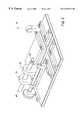
- FIG. 1depicts a machine base without cutting tools or modules.
- FIG. 2depicts a machine base with a cutting tool.
- FIG. 3depicts a machine base with a collet module in the perpendicular position.
- FIG. 4depicts a machine base with a collet module in the parallel position.
- FIG. 5depicts a machine base with a vise module.
- FIG. 6depicts a machine base with a threading module.
- FIG. 7depicts a collet module.
- FIG. 8depicts a vise module
- FIG. 9depicts a threading module.
- FIG. 1An embodiment of a machine base 10 without cutting tools or modules is shown in FIG. 1 .
- the machine base shownincludes perpendicular tracks defined by rails 34 , including a cutting tool track 12 and a track for the working modules 14 that intersect to form a cross shape. Both tracks contain a groove 16 to guide the motion of the various modules in the tracks.
- the machine base as shown in FIG. 1also includes a cutting tool module 18 configured to hold a standard high speed cutting tool. Such tools may be obtained from Dremel of Racine, Wis., for example. In the embodiment shown, the tool lies horizontally in the openings 20 .
- the cutting tool module 18is shown connected by an arm member 22 to a bar or rod 24 .
- the bar 24is shown attached to a knob 26 .
- bar 24may be threaded with threads 25 and may be configured to mate with threads in an opening 28 in the end of arm member 22 .
- turning knob 26is effective to move the cutting tool module 18 along the track 12 , and to thus move the cutting tool toward or away from a dowel during use.
- the embodiment shownalso includes a support member 30 having an opening 32 therethrough, which may in certain embodiments be a threaded opening configured with threads 25 to accept an extension, or a threaded extension of a working module during use.
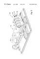
- FIG. 2A machine base 10 with a cutting tool 40 held in the cutting tool module 18 is shown in FIG. 2 .
- the cutting tool 40is connected to a switched motor by a cable (not shown) configured to turn a shaft in the tool 40 at high speed.
- Shown mounted on the cutting tool 40is a burr or bit 42 for working the dowel.
- a machine base 10 with a collet module 60 in the perpendicular positionis shown in FIG. 3.
- a collect module 60is also shown in isolation in FIG. 7 .
- the collect moduleincludes a collect 62 configured to hold a bone dowel.
- a knob 64may be connected to the collect 62 such that turning the knob turns the collect 62 and thus a dowel held in the collet 62 .
- a second knob 66may be connected to an extension 68 , preferably a threaded extension with threads 25 . As shown in FIG.
- extension 68may be received by support member 30 , such that when the extension 68 and the opening 32 include mating threading, turning of knob 66 is effective to move the collet module 60 along the track 14 , thus moving a dowel held in collect 62 perpendicular to a cutting tool 40 during use.
- the bottom to the collet modulemay include a projection 70 configured to ride in grooves 16 within tracks 12 and 14 of machine base 10 .
- flanges 72configured to mate with rails 34 . This configuration allows precise, controlled movement of the modules through the tracks.
- the collet moduleis most useful for holding a dowel by one end while smoothing and drilling holes in the opposite end of the dowel.
- a bone dowelmay be held by one end in the collet with the collet module in the perpendicular orientation.
- the collet modulemay be positioned next to the support member, so that the dowel does not extend over the cutting tool track 12 .
- the cutting tool modulemay be positioned such that the burr may extend over the track 14 .
- the cutting tool motormay be turned on so the burr is turning at high speed.
- FIG. 4depicts a machine base 10 with a collet module 60 in the parallel orientation as described. In the parallel orientation, the collet module 60 is preferably pushed along the track 12 by free hand, as the extension 68 is typically not engaged with a threaded opening.
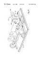
- a machine base 10 with a vise module 80is shown in FIG. 5 .
- An example of a vise module 80is shown in isolation in FIG. 8 .
- the vise module 80may be configured to hold a dowel so that an end of the dowel may be machined.
- a vise module 80may include a bottom as described for the collet module 60 , including a projection 90 configured to ride in grooves 16 within tracks 12 and 14 of machine base 10 . Also shown are flanges 92 , configured to mate with rails 34 .
- the bottom or base 96 of the vise module 80may also include a track 94 on its top for a moveable vise jaw 84 .
- the vise module 80may also include a stationary vise jaw 86 that provides a groove 88 configured to hold one side of a dowel.
- the vise module 80may also include a knob 82 connected to the moveable vise jaw 84 by a rod 95 .
- the rod 95may have threads 25 .
- Support member 98may provide a threaded opening, with threads that mate with threads on rod 95 such that turning knob 82 threads the rod 95 through the support member 98 , thus moving the moveable jaw 84 until it contacts the stationary jaw 86 , or a dowel held between the jaws of the vise.
- a dowelmay be held in the vise by force applied through turning of knob 82 .
- the vise module 80may be placed on the machine base 10 in the perpendicular orientation as shown in FIG. 5.
- a dowelmay be placed in the vise and secured by turning knob 82 until the pressure of the jaws is sufficient to hold the dowel.
- a cutting tool burrconfigured to produce a straight sided groove is mounted on the cutting tool and the tool is turned on.
- the vise modulemay then be moved past the cutting tool burr so that a groove is cut in the end of the dowel.
- the cutting tool modulemay then be moved closer to the vise module and the process repeated to deepen the groove as necessary.
- such a grooveis useful to mate with a screwdriver apparatus.
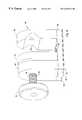
- a machine base 10 with a threading module 110 in the perpendicular orientationis shown in FIG. 6.
- a threading module 110is shown in isolation in FIG. 9 .
- the bottom of base 116 of the threading module 110may have the same configuration as the previously described modules including a projection 112 and flanges 114 for riding in the tracks 12 , 14 of machine base 10 .
- Base 116may also provide a groove 118 for tracking of the moveable member 120 of the threading module 110 .
- the moduleincludes a first support member 136 that provides an opening for a rod 138 that may pass through support member 136 and a moveable member 120 , and provide a dead center 130 configured to insert a point into a center hole drilled in the end of a dowel to be threaded.
- the rod 138may be bonded to member 120 and may also pass through a spring 132 disposed between member 136 and 120 during use. In the described configuration, the spring biases moveable member 120 toward member 134 .
- a disc 140may also be attached to member 120 to provide a solid surface for spring 132 .
- a threading module 110may also include an immobile support member 134 that provides a turning member or chuck 142 to hold a dowel to be threaded. As shown, a projection 128 may be provided to mate with a groove machined in an end of the dowel as described above. Also included in the embodiment of a threading module 110 is support member 122 , which provides an opening for threaded projection 126 . Threaded projection 126 may be configured with threads 25 to mate with the threaded opening 32 in support member 30 (FIG. 1 ). Threaded projection 126 may also be attached to a knob 124 configured such that turning the knob 124 is effective to thread the projection 126 through the opening 32 . The knob 124 may also be attached to the chuck 142 , such that turning the knob 124 also turns a dowel held by the chuck.
- the threading modulemay be placed on the machine base in the perpendicular orientation with projection 126 threaded through opening 32 , and a dowel may be placed in the threading module.
- the end having a centered drilled holemay contact the dead center, and the grooved end may contact the other member 142 of the module.
- the springmay provide the tension to hold a dowel in place.
- a threading burrmay be mounted on the cutting tool and the tool turned on.
- the cutting tool modulemay be moved toward the dowel by turning knob 26 as described above until the burr contacts the dowel.
- the burrmay contact the dowel at one end of the dowel. While the burr contacts the dowel, an operator may turn knob 124 , threading the projection through opening 32 .
- This motionmay serve to move the dowel past the burr and to simultaneously turn the dowel so that a thread is cut in the dowel.
- the threads in the dowelwill thus have the same pitch as the threads in opening 32 .
- the cutting toolmay then be moved closer to the dowel and the process repeated to make deeper threads as needed.
- the first step in a manufacturing proceduremay be to determine the size of the first dowel.
- Donor bonemay be first processed according to normal procedures of a bone tissue bank. The largest width of the medullary space may be measured and 6 mm may be added to this measurement to determine the smallest possible dowel that can be manufactured. The number may then be rounded up to the closest even number size (14, 16, 18, or 20 mm, for example).
- the medullary spacemay be then deburred with a small file, and the dowel may be washed and stored.
- the next step in processing the bonemay be to determine the size of the remaining dowels.
- the largest width of the exposed medullary spacemay be measured and a ring may be cut with a width equal to this largest width plus 8 mm.
- the largest width of the exposed medullary spacemay be measured on both sides of the ring and 6 mm may be added to this number to determine the smallest possible dowel that can be manufactured from this ring.
- the numbermay be rounded up as above (14, 16, 18, or 20 mm, for example). If the number is smaller than 14 mm, then preferably no dowel is made from that ring.
- a cylindrical dowelmay be cut from the ring (14.5, 16.5, 18.5, and 20.5 mm for this example), using care to ensure that the medullary space is centered in the dowel.
- the medullary spacemay be then deburred with a small file, and the dowel may be washed and stored.
- the dowelsare then machined to length. First the length of the medullary space may be measured, 6 mm may be added to the measurement, and the number may be rounded up to determine the smallest possible dowel length (18, 22, or 26 mm, for example). The dowel may be cut with a band saw to 2 mm longer than the length determined as the smallest possible length for that dowel while centering the medullary space. The dowel may be then washed and stored.
- the dowel prepared as describedmay be then ready for machining to its final shape.
- the machine basemay be set up with the cutting tool in place and the burr attached.
- the dowelmay be secured in the collet module, which may be placed in the base oriented perpendicular to the cutting tool.
- the distal end of the dowelmay then be machined until smooth, removing no more than 1 mm.
- the colletmay be then oriented parallel to the cutting tool and a pilot hole may be drilled in the center of the distal end of the dowel, using a drill bit.
- the dowelmay be flipped in the collet module and the proximal end machined until smooth and a pilot hole drilled as was done to the distal end.
- the drilled pilot holepreferably penetrates to the medullary space.
- a burrmay then be placed on the cutting tool and the dowel may be placed in the vise module.
- the vise modulemay be placed in the machine base in the parallel orientation and a groove machined into the proximal end of the dowel.
- the dowelmay be next mounted in the threading module, which may be placed in the machine base in the perpendicular orientation.
- the dowelmay be preferably mounted by supporting the pilot hole in the distal end of the dowel with the dead center and capturing the proximal end by the hole and groove.
- the thread cutting burrmay be mounted on the cutting tool.
- the threading moduleBefore cutting, the threading module may be moved into the base as far as possible.
- the cutting toolmay be turned on and advanced until the burr touches the dowel.
- the knob on the threading modulemay then be turned until the entire dowel has moved past the burr.
- the threading modulemay then be returned to the starting position, the burr may be advanced approximately 0.020 inches, and the knob may be turned to move the dowel past the burr.
- the diameter of the dowelmay then be measured using calipers, for example, and the process repeated until the desired diameter is achieved.
- the dowelmay then be processed, packaged and stored according to normal tissue bank procedures, or it may be
Landscapes
- Health & Medical Sciences (AREA)
- Engineering & Computer Science (AREA)
- Orthopedic Medicine & Surgery (AREA)
- Transplantation (AREA)
- Heart & Thoracic Surgery (AREA)
- Oral & Maxillofacial Surgery (AREA)
- Cardiology (AREA)
- Biomedical Technology (AREA)
- Vascular Medicine (AREA)
- Life Sciences & Earth Sciences (AREA)
- Animal Behavior & Ethology (AREA)
- General Health & Medical Sciences (AREA)
- Public Health (AREA)
- Veterinary Medicine (AREA)
- Physical Education & Sports Medicine (AREA)
- Mechanical Engineering (AREA)
- Surgical Instruments (AREA)
Abstract
Description
Claims (72)
Priority Applications (2)
| Application Number | Priority Date | Filing Date | Title |
|---|---|---|---|
| US09/298,269US6442814B1 (en) | 1999-04-23 | 1999-04-23 | Apparatus for manufacturing a bone dowel |
| US09/369,964US6557226B1 (en) | 1999-04-23 | 1999-08-06 | Apparatus for manufacturing a bone dowel |
Applications Claiming Priority (1)
| Application Number | Priority Date | Filing Date | Title |
|---|---|---|---|
| US09/298,269US6442814B1 (en) | 1999-04-23 | 1999-04-23 | Apparatus for manufacturing a bone dowel |
Related Child Applications (1)
| Application Number | Title | Priority Date | Filing Date |
|---|---|---|---|
| US09/369,964Continuation-In-PartUS6557226B1 (en) | 1999-04-23 | 1999-08-06 | Apparatus for manufacturing a bone dowel |
Publications (1)
| Publication Number | Publication Date |
|---|---|
| US6442814B1true US6442814B1 (en) | 2002-09-03 |
Family
ID=23149783
Family Applications (1)
| Application Number | Title | Priority Date | Filing Date |
|---|---|---|---|
| US09/298,269Expired - Fee RelatedUS6442814B1 (en) | 1999-04-23 | 1999-04-23 | Apparatus for manufacturing a bone dowel |
Country Status (1)
| Country | Link |
|---|---|
| US (1) | US6442814B1 (en) |
Cited By (60)
| Publication number | Priority date | Publication date | Assignee | Title |
|---|---|---|---|---|
| US6887248B2 (en) | 1998-05-27 | 2005-05-03 | Nuvasive, Inc. | Bone blocks and methods for inserting bone blocks into intervertebral spaces |
| US20050125986A1 (en)* | 2003-12-16 | 2005-06-16 | Stryker Spine | Apparatus and method for cutting spinal implants |
| US6923814B1 (en) | 2001-10-30 | 2005-08-02 | Nuvasive, Inc. | System and methods for cervical spinal fusion |
| USD530423S1 (en) | 2005-03-29 | 2006-10-17 | Nuvasive, Inc. | Intervertebral implant |
| US20070135917A1 (en)* | 2005-10-26 | 2007-06-14 | Malinin Theodore I | Instrumentation for the preparation and transplantation of osteochondral allografts |
| US20080011133A1 (en)* | 2006-06-27 | 2008-01-17 | Karahalios Dean G | Devices and methods for cutting a vertebral implant |
| US20090093853A1 (en)* | 2007-10-05 | 2009-04-09 | Biomet Manufacturing Corp. | System For Forming A Tendon-Bone Graft |
| US20090173195A1 (en)* | 2008-01-04 | 2009-07-09 | Jack Yang | Adjustable wood lathe |
| USD599019S1 (en) | 2008-03-07 | 2009-08-25 | Nuvasive, Inc. | Spinal fusion implant |
| US20090222052A1 (en)* | 2007-10-05 | 2009-09-03 | Biomet Manufacturing Corp. | System For Forming A Tendon-Bone Graft |
| US7618423B1 (en) | 2002-06-15 | 2009-11-17 | Nuvasive, Inc. | System and method for performing spinal fusion |
| US7708778B2 (en) | 2003-08-05 | 2010-05-04 | Flexuspine, Inc. | Expandable articulating intervertebral implant with cam |
| US7776049B1 (en) | 2002-10-02 | 2010-08-17 | Nuvasive, Inc. | Spinal implant inserter, implant, and method |
| US7785351B2 (en) | 2003-08-05 | 2010-08-31 | Flexuspine, Inc. | Artificial functional spinal implant unit system and method for use |
| US7887568B2 (en) | 2000-07-17 | 2011-02-15 | Nuvasive, Inc. | Stackable spinal support system and related methods |
| US7909869B2 (en) | 2003-08-05 | 2011-03-22 | Flexuspine, Inc. | Artificial spinal unit assemblies |
| US7918891B1 (en) | 2004-03-29 | 2011-04-05 | Nuvasive Inc. | Systems and methods for spinal fusion |
| US7959677B2 (en) | 2007-01-19 | 2011-06-14 | Flexuspine, Inc. | Artificial functional spinal unit system and method for use |
| US8118869B2 (en) | 2006-03-08 | 2012-02-21 | Flexuspine, Inc. | Dynamic interbody device |
| US8157844B2 (en) | 2007-10-22 | 2012-04-17 | Flexuspine, Inc. | Dampener system for a posterior stabilization system with a variable length elongated member |
| US8162994B2 (en) | 2007-10-22 | 2012-04-24 | Flexuspine, Inc. | Posterior stabilization system with isolated, dual dampener systems |
| US8182514B2 (en) | 2007-10-22 | 2012-05-22 | Flexuspine, Inc. | Dampener system for a posterior stabilization system with a fixed length elongated member |
| US8187330B2 (en) | 2007-10-22 | 2012-05-29 | Flexuspine, Inc. | Dampener system for a posterior stabilization system with a variable length elongated member |
| US8202304B2 (en) | 2002-08-21 | 2012-06-19 | Theken Spine, Llc | Methods and systems for performing spinal surgery |
| US8267965B2 (en) | 2007-10-22 | 2012-09-18 | Flexuspine, Inc. | Spinal stabilization systems with dynamic interbody devices |
| US8287597B1 (en) | 2009-04-16 | 2012-10-16 | Nuvasive, Inc. | Method and apparatus for performing spine surgery |
| USD671645S1 (en) | 2007-09-18 | 2012-11-27 | Nuvasive, Inc. | Intervertebral implant |
| US8328851B2 (en) | 2005-07-28 | 2012-12-11 | Nuvasive, Inc. | Total disc replacement system and related methods |
| US8523912B2 (en) | 2007-10-22 | 2013-09-03 | Flexuspine, Inc. | Posterior stabilization systems with shared, dual dampener systems |
| US8623088B1 (en) | 2005-07-15 | 2014-01-07 | Nuvasive, Inc. | Spinal fusion implant and related methods |
| US8673005B1 (en) | 2007-03-07 | 2014-03-18 | Nuvasive, Inc. | System and methods for spinal fusion |
| US8747476B2 (en) | 1999-03-07 | 2014-06-10 | Nuvasive, Inc. | Spinal implant system |
| US8940051B2 (en) | 2011-03-25 | 2015-01-27 | Flexuspine, Inc. | Interbody device insertion systems and methods |
| USD721808S1 (en) | 2011-11-03 | 2015-01-27 | Nuvasive, Inc. | Intervertebral implant |
| USD731063S1 (en) | 2009-10-13 | 2015-06-02 | Nuvasive, Inc. | Spinal fusion implant |
| USD735336S1 (en) | 2008-10-15 | 2015-07-28 | Nuvasive, Inc. | Intervertebral implant |
| US9101491B2 (en) | 2007-12-28 | 2015-08-11 | Nuvasive, Inc. | Spinal surgical implant and related methods |
| USD741488S1 (en) | 2006-07-17 | 2015-10-20 | Nuvasive, Inc. | Spinal fusion implant |
| US9168152B2 (en) | 2008-02-29 | 2015-10-27 | Nuvasive, Inc. | Implants and methods for spinal fusion |
| US9198765B1 (en) | 2011-10-31 | 2015-12-01 | Nuvasive, Inc. | Expandable spinal fusion implants and related methods |
| USD745159S1 (en) | 2013-10-10 | 2015-12-08 | Nuvasive, Inc. | Intervertebral implant |
| USD747485S1 (en) | 2011-11-03 | 2016-01-12 | Nuvasive, Inc. | Intervertebral implant |
| USD754346S1 (en) | 2009-03-02 | 2016-04-19 | Nuvasive, Inc. | Spinal fusion implant |
| US9351845B1 (en) | 2009-04-16 | 2016-05-31 | Nuvasive, Inc. | Method and apparatus for performing spine surgery |
| US9387090B2 (en) | 2009-03-12 | 2016-07-12 | Nuvasive, Inc. | Vertebral body replacement |
| US9492288B2 (en) | 2013-02-20 | 2016-11-15 | Flexuspine, Inc. | Expandable fusion device for positioning between adjacent vertebral bodies |
| US9517144B2 (en) | 2014-04-24 | 2016-12-13 | Exactech, Inc. | Limited profile intervertebral implant with incorporated fastening mechanism |
| US9526627B2 (en) | 2011-11-17 | 2016-12-27 | Exactech, Inc. | Expandable interbody device system and method |
| US9687357B2 (en) | 2009-03-12 | 2017-06-27 | Nuvasive, Inc. | Vertebral body replacement |
| US9750490B2 (en) | 2002-06-26 | 2017-09-05 | Nuvasive, Inc. | Surgical access system and related methods |
| US9788822B2 (en) | 2003-09-25 | 2017-10-17 | Nuvasive, Inc. | Surgical access system and related methods |
| US9795371B2 (en) | 2003-01-16 | 2017-10-24 | Nuvasive, Inc. | Surgical access system and related methods |
| US9820729B2 (en) | 2002-10-08 | 2017-11-21 | Nuvasive, Inc. | Surgical access system and related methods |
| US9931077B2 (en) | 2001-07-11 | 2018-04-03 | Nuvasive, Inc. | System and methods for determining nerve proximity, direction and pathology during surgery |
| US9949840B1 (en) | 2011-04-01 | 2018-04-24 | William D. Smith | Systems and methods for performing spine surgery |
| USD858769S1 (en) | 2014-11-20 | 2019-09-03 | Nuvasive, Inc. | Intervertebral implant |
| US10398565B2 (en) | 2014-04-24 | 2019-09-03 | Choice Spine, Llc | Limited profile intervertebral implant with incorporated fastening and locking mechanism |
| US10507120B2 (en) | 2001-09-25 | 2019-12-17 | Nuvasive, Inc. | Systems and methods for performing surgical procedures and assessments |
| US10653308B2 (en) | 2003-10-17 | 2020-05-19 | Nuvasive, Inc. | Surgical access system and related methods |
| US11213406B2 (en)* | 2019-07-10 | 2022-01-04 | Arthrex, Inc. | Graft preparation station for repairing bone defects |
Citations (84)
| Publication number | Priority date | Publication date | Assignee | Title |
|---|---|---|---|---|
| US1358040A (en)* | 1918-02-23 | 1920-11-09 | American Multigraph Co | Milling-machine |
| US2028727A (en)* | 1933-11-23 | 1936-01-21 | Ingersoll Milling Machine Co | Construction of machine tools |
| US2370286A (en)* | 1941-12-18 | 1945-02-27 | Karl F Berger | Lathe |
| US2378302A (en)* | 1942-08-22 | 1945-06-12 | Micromatic Hone Corp | Method and means for generating helices |
| US2388152A (en)* | 1944-01-08 | 1945-10-30 | Western Electric Co | Material working apparatus |
| US3222052A (en)* | 1963-10-18 | 1965-12-07 | Freda Francis | Controllably adjustable mounting means |
| US3470789A (en)* | 1967-02-23 | 1969-10-07 | Glenn B Morse | Multiple purpose machine |
| US3704648A (en)* | 1971-07-12 | 1972-12-05 | Walter S Burfoot | Thread milling attachment for engine lathes |
| US3848601A (en) | 1972-06-14 | 1974-11-19 | G Ma | Method for interbody fusion of the spine |
| US3988814A (en) | 1973-03-21 | 1976-11-02 | Hoffman Robert E | Milling machine |
| US4044650A (en) | 1976-01-16 | 1977-08-30 | Hardinge Brothers, Inc. | Milling attachment for a lathe |
| US4057893A (en) | 1976-04-07 | 1977-11-15 | Still-Walter Tool & Manufacturing Company | Milling table lathe |
| GB2025282A (en)* | 1978-07-17 | 1980-01-23 | Heinemann R A | Multi-purpose Machine Tool |
| US4401112A (en) | 1980-09-15 | 1983-08-30 | Rezaian Seyed M | Spinal fixator |
| US4501269A (en) | 1981-12-11 | 1985-02-26 | Washington State University Research Foundation, Inc. | Process for fusing bone joints |
| US4515191A (en) | 1983-08-22 | 1985-05-07 | Fetty James R | Radial universal tool |
| US4566169A (en)* | 1983-01-10 | 1986-01-28 | Maier & Co. | Set of parts for building small machine tools |
| US4625377A (en)* | 1983-12-20 | 1986-12-02 | Kavthekar Keshav S | Method for manufacturing universal joints |
| US4714469A (en) | 1987-02-26 | 1987-12-22 | Pfizer Hospital Products Group, Inc. | Spinal implant |
| US4719676A (en)* | 1984-09-10 | 1988-01-19 | Wadell Equipment Company, Inc. | Flexible machining system |
| EP0260044A1 (en) | 1986-08-29 | 1988-03-16 | John Anthony Norman Shepperd | Spinal implant |
| US4743146A (en) | 1986-10-02 | 1988-05-10 | Kharkovsky Filial Golovnogo Spetsialnogo Proizvodstvennogo Konstruktorsko-Tekhnologicheskogo Bjuro Po Ratsionalnomu Primeneniju Rezhuschego Instrumenta "Orgpriminstrument" | Tool for cutting external threads |
| US4743256A (en) | 1985-10-04 | 1988-05-10 | Brantigan John W | Surgical prosthetic implant facilitating vertebral interbody fusion and method |
| WO1988006943A1 (en)* | 1987-03-17 | 1988-09-22 | Kitamura Machinery Co., Ltd. | Machine tool |
| SU1424826A1 (en) | 1986-05-22 | 1988-09-23 | Белорусский научно-исследовательский институт травматологии и ортопедии | Fixative for spinal column |
| US4777713A (en)* | 1986-04-04 | 1988-10-18 | Kitamura Machinery Co., Ltd. | Machine tool |
| EP0307241A2 (en) | 1987-09-11 | 1989-03-15 | John W. Brantigan | Surgical prosthetic implant |
| US4856503A (en) | 1987-08-15 | 1989-08-15 | Orthoplant Endoprothetik Gmbh | Device for cutting a thread in a cup-shaped bone |
| US4867620A (en) | 1988-10-13 | 1989-09-19 | Newact, Incorporated | Protective device for a machine tool |
| US4877020A (en) | 1984-11-30 | 1989-10-31 | Vich Jose M O | Apparatus for bone graft |
| US4904261A (en) | 1987-08-06 | 1990-02-27 | A. W. Showell (Surgicraft) Limited | Spinal implants |
| US4936848A (en) | 1989-09-22 | 1990-06-26 | Bagby George W | Implant for vertebrae |
| US4950296A (en) | 1988-04-07 | 1990-08-21 | Mcintyre Jonathan L | Bone grafting units |
| US4961740A (en) | 1988-10-17 | 1990-10-09 | Surgical Dynamics, Inc. | V-thread fusion cage and method of fusing a bone joint |
| JPH0386407A (en)* | 1989-08-31 | 1991-04-11 | Okuma Mach Works Ltd | Y-axis machining device |
| US5015255A (en) | 1989-05-10 | 1991-05-14 | Spine-Tech, Inc. | Spinal stabilization method |
| US5015247A (en) | 1988-06-13 | 1991-05-14 | Michelson Gary K | Threaded spinal implant |
| US5052089A (en)* | 1988-05-25 | 1991-10-01 | Somab, S.A. | Multi-function machine tool which permits complex machining of long pieces |
| US5055104A (en) | 1989-11-06 | 1991-10-08 | Surgical Dynamics, Inc. | Surgically implanting threaded fusion cages between adjacent low-back vertebrae by an anterior approach |
| US5090279A (en) | 1989-09-06 | 1992-02-25 | Emco Maier Gmbh | Vertical spindle pedestal |
| US5112354A (en) | 1989-11-16 | 1992-05-12 | Northwestern University | Bone allograft material and method |
| US5123926A (en) | 1991-02-22 | 1992-06-23 | Madhavan Pisharodi | Artificial spinal prosthesis |
| US5147402A (en) | 1990-12-05 | 1992-09-15 | Sulzer Brothers Limited | Implant for ingrowth of osseous tissue |
| US5171278A (en) | 1991-02-22 | 1992-12-15 | Madhavan Pisharodi | Middle expandable intervertebral disk implants |
| US5192327A (en) | 1991-03-22 | 1993-03-09 | Brantigan John W | Surgical prosthetic implant for vertebrae |
| US5263953A (en) | 1991-12-31 | 1993-11-23 | Spine-Tech, Inc. | Apparatus and system for fusing bone joints |
| US5301405A (en) | 1993-01-11 | 1994-04-12 | Maker Richard A | Milling machine lathe attachment |
| US5306307A (en) | 1991-07-22 | 1994-04-26 | Calcitek, Inc. | Spinal disk implant |
| US5306309A (en) | 1992-05-04 | 1994-04-26 | Calcitek, Inc. | Spinal disk implant and implantation kit |
| US5333657A (en) | 1992-10-13 | 1994-08-02 | Larry Hart | Workpiece turing and milling apparatus |
| US5336240A (en) | 1991-03-04 | 1994-08-09 | Liebscherkunststofftechnik | Bone-dowel assembly for anchoring a suture |
| US5370697A (en) | 1992-04-21 | 1994-12-06 | Sulzer Medizinaltechnik Ag | Artificial intervertebral disk member |
| US5390683A (en) | 1991-02-22 | 1995-02-21 | Pisharodi; Madhavan | Spinal implantation methods utilizing a middle expandable implant |
| US5397364A (en) | 1993-10-12 | 1995-03-14 | Danek Medical, Inc. | Anterior interbody fusion device |
| US5425772A (en) | 1993-09-20 | 1995-06-20 | Brantigan; John W. | Prosthetic implant for intervertebral spinal fusion |
| US5443514A (en) | 1993-10-01 | 1995-08-22 | Acromed Corporation | Method for using spinal implants |
| FR2717068A1 (en) | 1994-03-14 | 1995-09-15 | Biomat | Intersomatic cage insertable between two vertebral bodies |
| US5458638A (en) | 1989-07-06 | 1995-10-17 | Spine-Tech, Inc. | Non-threaded spinal implant |
| US5484437A (en) | 1988-06-13 | 1996-01-16 | Michelson; Gary K. | Apparatus and method of inserting spinal implants |
| US5489307A (en) | 1993-02-10 | 1996-02-06 | Spine-Tech, Inc. | Spinal stabilization surgical method |
| US5522899A (en) | 1988-06-28 | 1996-06-04 | Sofamor Danek Properties, Inc. | Artificial spinal fusion implants |
| US5536271A (en) | 1994-06-02 | 1996-07-16 | Depuy, Inc. | Patella reaming system |
| US5571195A (en) | 1995-05-30 | 1996-11-05 | Johnson; Lanny L. | Prothesis for an artificial joint having a wear particle collection capability |
| WO1997000054A1 (en) | 1995-06-19 | 1997-01-03 | Sven Olerud | An adjustable spacing device and a method of adjusting the distance between two vertebrae with the aid of said spacing device in spinal surgical operations |
| US5593409A (en) | 1988-06-13 | 1997-01-14 | Sofamor Danek Group, Inc. | Interbody spinal fusion implants |
| US5601556A (en) | 1994-03-18 | 1997-02-11 | Pisharodi; Madhavan | Apparatus for spondylolisthesis reduction |
| WO1997006753A2 (en) | 1995-08-11 | 1997-02-27 | Bernhard Zientek | Intervertebral implant, process for widening and instruments for implanting an intervertebral implant |
| US5607424A (en) | 1995-04-10 | 1997-03-04 | Tropiano; Patrick | Domed cage |
| US5609636A (en) | 1994-05-23 | 1997-03-11 | Spine-Tech, Inc. | Spinal implant |
| US5609635A (en) | 1988-06-28 | 1997-03-11 | Michelson; Gary K. | Lordotic interbody spinal fusion implants |
| US5632747A (en) | 1995-03-15 | 1997-05-27 | Osteotech, Inc. | Bone dowel cutter |
| US5645598A (en) | 1996-01-16 | 1997-07-08 | Smith & Nephew, Inc. | Spinal fusion device with porous material |
| US5653763A (en) | 1996-03-29 | 1997-08-05 | Fastenetix, L.L.C. | Intervertebral space shape conforming cage device |
| US5665122A (en) | 1995-01-31 | 1997-09-09 | Kambin; Parviz | Expandable intervertebral cage and surgical method |
| US5669909A (en) | 1995-03-27 | 1997-09-23 | Danek Medical, Inc. | Interbody fusion device and method for restoration of normal spinal anatomy |
| WO1998017209A2 (en) | 1996-10-23 | 1998-04-30 | Sdgi Holdings, Inc. | Spinal spacer |
| US5797917A (en) | 1995-06-07 | 1998-08-25 | Sdgi Holdings, Inc. | Anterior spinal instrumentation and method for implantation and revision |
| US5814084A (en) | 1996-01-16 | 1998-09-29 | University Of Florida Tissue Bank, Inc. | Diaphysial cortical dowel |
| WO1998055052A1 (en) | 1997-06-03 | 1998-12-10 | Sdgi Holdings, Inc. | Open intervertebral spacer |
| US5964016A (en)* | 1996-09-04 | 1999-10-12 | Kawasaki Jukogyo Kabushiki Kaisha | Long bar member machining apparatus |
| US6095728A (en) | 1997-04-29 | 2000-08-01 | Howie; Frederick Victor Steven | Translation apparatus |
| US6131259A (en) | 1996-08-30 | 2000-10-17 | Stama Maschinenfabrik Gmbh | Drilling and milling mechanism for machining material rods |
| US6155756A (en) | 1998-12-30 | 2000-12-05 | Musculoskeletal Transplant Foundation | Thread forming machine for bone material |
| US6231577B1 (en) | 1999-08-12 | 2001-05-15 | James T. Canedy | Device for creating cylindrical bone plugs for patella-patellar tendon-tibia grafts |
- 1999
- 1999-04-23USUS09/298,269patent/US6442814B1/ennot_activeExpired - Fee Related
Patent Citations (95)
| Publication number | Priority date | Publication date | Assignee | Title |
|---|---|---|---|---|
| US1358040A (en)* | 1918-02-23 | 1920-11-09 | American Multigraph Co | Milling-machine |
| US2028727A (en)* | 1933-11-23 | 1936-01-21 | Ingersoll Milling Machine Co | Construction of machine tools |
| US2370286A (en)* | 1941-12-18 | 1945-02-27 | Karl F Berger | Lathe |
| US2378302A (en)* | 1942-08-22 | 1945-06-12 | Micromatic Hone Corp | Method and means for generating helices |
| US2388152A (en)* | 1944-01-08 | 1945-10-30 | Western Electric Co | Material working apparatus |
| US3222052A (en)* | 1963-10-18 | 1965-12-07 | Freda Francis | Controllably adjustable mounting means |
| US3470789A (en)* | 1967-02-23 | 1969-10-07 | Glenn B Morse | Multiple purpose machine |
| US3704648A (en)* | 1971-07-12 | 1972-12-05 | Walter S Burfoot | Thread milling attachment for engine lathes |
| US3848601A (en) | 1972-06-14 | 1974-11-19 | G Ma | Method for interbody fusion of the spine |
| US3988814A (en) | 1973-03-21 | 1976-11-02 | Hoffman Robert E | Milling machine |
| US4044650A (en) | 1976-01-16 | 1977-08-30 | Hardinge Brothers, Inc. | Milling attachment for a lathe |
| US4057893A (en) | 1976-04-07 | 1977-11-15 | Still-Walter Tool & Manufacturing Company | Milling table lathe |
| GB2025282A (en)* | 1978-07-17 | 1980-01-23 | Heinemann R A | Multi-purpose Machine Tool |
| US4401112A (en) | 1980-09-15 | 1983-08-30 | Rezaian Seyed M | Spinal fixator |
| US4501269A (en) | 1981-12-11 | 1985-02-26 | Washington State University Research Foundation, Inc. | Process for fusing bone joints |
| US4566169A (en)* | 1983-01-10 | 1986-01-28 | Maier & Co. | Set of parts for building small machine tools |
| US4515191A (en) | 1983-08-22 | 1985-05-07 | Fetty James R | Radial universal tool |
| US4625377A (en)* | 1983-12-20 | 1986-12-02 | Kavthekar Keshav S | Method for manufacturing universal joints |
| US4719676A (en)* | 1984-09-10 | 1988-01-19 | Wadell Equipment Company, Inc. | Flexible machining system |
| US4877020A (en) | 1984-11-30 | 1989-10-31 | Vich Jose M O | Apparatus for bone graft |
| US4743256A (en) | 1985-10-04 | 1988-05-10 | Brantigan John W | Surgical prosthetic implant facilitating vertebral interbody fusion and method |
| US4777713A (en)* | 1986-04-04 | 1988-10-18 | Kitamura Machinery Co., Ltd. | Machine tool |
| SU1424826A1 (en) | 1986-05-22 | 1988-09-23 | Белорусский научно-исследовательский институт травматологии и ортопедии | Fixative for spinal column |
| US4863476A (en) | 1986-08-29 | 1989-09-05 | Shepperd John A N | Spinal implant |
| EP0260044A1 (en) | 1986-08-29 | 1988-03-16 | John Anthony Norman Shepperd | Spinal implant |
| US4743146A (en) | 1986-10-02 | 1988-05-10 | Kharkovsky Filial Golovnogo Spetsialnogo Proizvodstvennogo Konstruktorsko-Tekhnologicheskogo Bjuro Po Ratsionalnomu Primeneniju Rezhuschego Instrumenta "Orgpriminstrument" | Tool for cutting external threads |
| US4834757A (en) | 1987-01-22 | 1989-05-30 | Brantigan John W | Prosthetic implant |
| US4878915A (en) | 1987-01-22 | 1989-11-07 | Brantigan John W | Surgical prosthetic implant facilitating vertebral interbody fusion |
| US4714469A (en) | 1987-02-26 | 1987-12-22 | Pfizer Hospital Products Group, Inc. | Spinal implant |
| WO1988006943A1 (en)* | 1987-03-17 | 1988-09-22 | Kitamura Machinery Co., Ltd. | Machine tool |
| US4904261A (en) | 1987-08-06 | 1990-02-27 | A. W. Showell (Surgicraft) Limited | Spinal implants |
| US4856503A (en) | 1987-08-15 | 1989-08-15 | Orthoplant Endoprothetik Gmbh | Device for cutting a thread in a cup-shaped bone |
| EP0307241A2 (en) | 1987-09-11 | 1989-03-15 | John W. Brantigan | Surgical prosthetic implant |
| US4950296A (en) | 1988-04-07 | 1990-08-21 | Mcintyre Jonathan L | Bone grafting units |
| US5052089A (en)* | 1988-05-25 | 1991-10-01 | Somab, S.A. | Multi-function machine tool which permits complex machining of long pieces |
| US5484437A (en) | 1988-06-13 | 1996-01-16 | Michelson; Gary K. | Apparatus and method of inserting spinal implants |
| US5593409A (en) | 1988-06-13 | 1997-01-14 | Sofamor Danek Group, Inc. | Interbody spinal fusion implants |
| US5785710A (en) | 1988-06-13 | 1998-07-28 | Sofamor Danek Group, Inc. | Interbody spinal fusion implants |
| US5505732A (en) | 1988-06-13 | 1996-04-09 | Michelson; Gary K. | Apparatus and method of inserting spinal implants |
| US5015247A (en) | 1988-06-13 | 1991-05-14 | Michelson Gary K | Threaded spinal implant |
| US5776199A (en) | 1988-06-28 | 1998-07-07 | Sofamor Danek Properties | Artificial spinal fusion implants |
| US5522899A (en) | 1988-06-28 | 1996-06-04 | Sofamor Danek Properties, Inc. | Artificial spinal fusion implants |
| US5609635A (en) | 1988-06-28 | 1997-03-11 | Michelson; Gary K. | Lordotic interbody spinal fusion implants |
| US4867620A (en) | 1988-10-13 | 1989-09-19 | Newact, Incorporated | Protective device for a machine tool |
| US4961740A (en) | 1988-10-17 | 1990-10-09 | Surgical Dynamics, Inc. | V-thread fusion cage and method of fusing a bone joint |
| US4961740B1 (en) | 1988-10-17 | 1997-01-14 | Surgical Dynamics Inc | V-thread fusion cage and method of fusing a bone joint |
| US5026373A (en) | 1988-10-17 | 1991-06-25 | Surgical Dynamics, Inc. | Surgical method and apparatus for fusing adjacent bone structures |
| US5015255A (en) | 1989-05-10 | 1991-05-14 | Spine-Tech, Inc. | Spinal stabilization method |
| US5489308A (en) | 1989-07-06 | 1996-02-06 | Spine-Tech, Inc. | Spinal implant |
| US5458638A (en) | 1989-07-06 | 1995-10-17 | Spine-Tech, Inc. | Non-threaded spinal implant |
| JPH0386407A (en)* | 1989-08-31 | 1991-04-11 | Okuma Mach Works Ltd | Y-axis machining device |
| US5090279A (en) | 1989-09-06 | 1992-02-25 | Emco Maier Gmbh | Vertical spindle pedestal |
| US4936848A (en) | 1989-09-22 | 1990-06-26 | Bagby George W | Implant for vertebrae |
| US5055104A (en) | 1989-11-06 | 1991-10-08 | Surgical Dynamics, Inc. | Surgically implanting threaded fusion cages between adjacent low-back vertebrae by an anterior approach |
| US5112354A (en) | 1989-11-16 | 1992-05-12 | Northwestern University | Bone allograft material and method |
| US5147402A (en) | 1990-12-05 | 1992-09-15 | Sulzer Brothers Limited | Implant for ingrowth of osseous tissue |
| US5123926A (en) | 1991-02-22 | 1992-06-23 | Madhavan Pisharodi | Artificial spinal prosthesis |
| US5171278A (en) | 1991-02-22 | 1992-12-15 | Madhavan Pisharodi | Middle expandable intervertebral disk implants |
| US5390683A (en) | 1991-02-22 | 1995-02-21 | Pisharodi; Madhavan | Spinal implantation methods utilizing a middle expandable implant |
| US5336240A (en) | 1991-03-04 | 1994-08-09 | Liebscherkunststofftechnik | Bone-dowel assembly for anchoring a suture |
| US5192327A (en) | 1991-03-22 | 1993-03-09 | Brantigan John W | Surgical prosthetic implant for vertebrae |
| US5306307A (en) | 1991-07-22 | 1994-04-26 | Calcitek, Inc. | Spinal disk implant |
| US5263953A (en) | 1991-12-31 | 1993-11-23 | Spine-Tech, Inc. | Apparatus and system for fusing bone joints |
| US5370697A (en) | 1992-04-21 | 1994-12-06 | Sulzer Medizinaltechnik Ag | Artificial intervertebral disk member |
| US5306309A (en) | 1992-05-04 | 1994-04-26 | Calcitek, Inc. | Spinal disk implant and implantation kit |
| US5333657A (en) | 1992-10-13 | 1994-08-02 | Larry Hart | Workpiece turing and milling apparatus |
| US5301405A (en) | 1993-01-11 | 1994-04-12 | Maker Richard A | Milling machine lathe attachment |
| US5489307A (en) | 1993-02-10 | 1996-02-06 | Spine-Tech, Inc. | Spinal stabilization surgical method |
| US5425772A (en) | 1993-09-20 | 1995-06-20 | Brantigan; John W. | Prosthetic implant for intervertebral spinal fusion |
| US5443514A (en) | 1993-10-01 | 1995-08-22 | Acromed Corporation | Method for using spinal implants |
| US5397364A (en) | 1993-10-12 | 1995-03-14 | Danek Medical, Inc. | Anterior interbody fusion device |
| FR2717068A1 (en) | 1994-03-14 | 1995-09-15 | Biomat | Intersomatic cage insertable between two vertebral bodies |
| US5601556A (en) | 1994-03-18 | 1997-02-11 | Pisharodi; Madhavan | Apparatus for spondylolisthesis reduction |
| US5609636A (en) | 1994-05-23 | 1997-03-11 | Spine-Tech, Inc. | Spinal implant |
| US5658337A (en) | 1994-05-23 | 1997-08-19 | Spine-Tech, Inc. | Intervertebral fusion implant |
| US5536271A (en) | 1994-06-02 | 1996-07-16 | Depuy, Inc. | Patella reaming system |
| US5665122A (en) | 1995-01-31 | 1997-09-09 | Kambin; Parviz | Expandable intervertebral cage and surgical method |
| US5632747A (en) | 1995-03-15 | 1997-05-27 | Osteotech, Inc. | Bone dowel cutter |
| US5669909A (en) | 1995-03-27 | 1997-09-23 | Danek Medical, Inc. | Interbody fusion device and method for restoration of normal spinal anatomy |
| US5607424A (en) | 1995-04-10 | 1997-03-04 | Tropiano; Patrick | Domed cage |
| US5571195A (en) | 1995-05-30 | 1996-11-05 | Johnson; Lanny L. | Prothesis for an artificial joint having a wear particle collection capability |
| US5797917A (en) | 1995-06-07 | 1998-08-25 | Sdgi Holdings, Inc. | Anterior spinal instrumentation and method for implantation and revision |
| WO1997000054A1 (en) | 1995-06-19 | 1997-01-03 | Sven Olerud | An adjustable spacing device and a method of adjusting the distance between two vertebrae with the aid of said spacing device in spinal surgical operations |
| WO1997006753A2 (en) | 1995-08-11 | 1997-02-27 | Bernhard Zientek | Intervertebral implant, process for widening and instruments for implanting an intervertebral implant |
| US6096081A (en) | 1996-01-16 | 2000-08-01 | University Of Florida Tissue Bank, Inc. | Diaphysial cortical dowel |
| US5645598A (en) | 1996-01-16 | 1997-07-08 | Smith & Nephew, Inc. | Spinal fusion device with porous material |
| US5814084A (en) | 1996-01-16 | 1998-09-29 | University Of Florida Tissue Bank, Inc. | Diaphysial cortical dowel |
| US5653763A (en) | 1996-03-29 | 1997-08-05 | Fastenetix, L.L.C. | Intervertebral space shape conforming cage device |
| US6131259A (en) | 1996-08-30 | 2000-10-17 | Stama Maschinenfabrik Gmbh | Drilling and milling mechanism for machining material rods |
| US5964016A (en)* | 1996-09-04 | 1999-10-12 | Kawasaki Jukogyo Kabushiki Kaisha | Long bar member machining apparatus |
| WO1998017209A2 (en) | 1996-10-23 | 1998-04-30 | Sdgi Holdings, Inc. | Spinal spacer |
| US6095728A (en) | 1997-04-29 | 2000-08-01 | Howie; Frederick Victor Steven | Translation apparatus |
| WO1998055052A1 (en) | 1997-06-03 | 1998-12-10 | Sdgi Holdings, Inc. | Open intervertebral spacer |
| US6155756A (en) | 1998-12-30 | 2000-12-05 | Musculoskeletal Transplant Foundation | Thread forming machine for bone material |
| US6231577B1 (en) | 1999-08-12 | 2001-05-15 | James T. Canedy | Device for creating cylindrical bone plugs for patella-patellar tendon-tibia grafts |
Non-Patent Citations (52)
Cited By (160)
| Publication number | Priority date | Publication date | Assignee | Title |
|---|---|---|---|---|
| US7776094B2 (en) | 1998-05-27 | 2010-08-17 | Nuvasive, Inc. | Spinal implants and methods for inserting spinal implants into intervertebral spaces |
| US6887248B2 (en) | 1998-05-27 | 2005-05-03 | Nuvasive, Inc. | Bone blocks and methods for inserting bone blocks into intervertebral spaces |
| US8747476B2 (en) | 1999-03-07 | 2014-06-10 | Nuvasive, Inc. | Spinal implant system |
| US9398962B2 (en) | 1999-03-07 | 2016-07-26 | Nuvasive, Inc. | Spinal implant system |
| US8460384B2 (en) | 2000-07-17 | 2013-06-11 | Nuvasive, Inc. | Stackable spinal support system |
| US10390961B2 (en) | 2000-07-17 | 2019-08-27 | Nuvasive, Inc. | Stackable interlocking intervertebral support system |
| US7887568B2 (en) | 2000-07-17 | 2011-02-15 | Nuvasive, Inc. | Stackable spinal support system and related methods |
| US9101484B2 (en) | 2000-07-17 | 2015-08-11 | Nuvasive, Inc. | Stackable spinal support system |
| US8475496B2 (en) | 2000-07-17 | 2013-07-02 | Nuvasive, Inc. | Stackable spinal support system |
| US9931077B2 (en) | 2001-07-11 | 2018-04-03 | Nuvasive, Inc. | System and methods for determining nerve proximity, direction and pathology during surgery |
| US10507120B2 (en) | 2001-09-25 | 2019-12-17 | Nuvasive, Inc. | Systems and methods for performing surgical procedures and assessments |
| US6923814B1 (en) | 2001-10-30 | 2005-08-02 | Nuvasive, Inc. | System and methods for cervical spinal fusion |
| US7618423B1 (en) | 2002-06-15 | 2009-11-17 | Nuvasive, Inc. | System and method for performing spinal fusion |
| US9833227B2 (en) | 2002-06-26 | 2017-12-05 | Nuvasive, Inc. | Surgical access system and related methods |
| US9750490B2 (en) | 2002-06-26 | 2017-09-05 | Nuvasive, Inc. | Surgical access system and related methods |
| US9826968B2 (en) | 2002-06-26 | 2017-11-28 | Nuvasive, Inc. | Surgical access system and related methods |
| US9848861B2 (en) | 2002-06-26 | 2017-12-26 | Nuvasive, Inc. | Surgical access system and related methods |
| US10251633B2 (en) | 2002-06-26 | 2019-04-09 | Nuvasive, Inc. | Surgical access system and related methods |
| US8202304B2 (en) | 2002-08-21 | 2012-06-19 | Theken Spine, Llc | Methods and systems for performing spinal surgery |
| US8382802B2 (en) | 2002-08-21 | 2013-02-26 | Theken Spine, Llc | Systems, methods and devices for placement of bone anchors and connectors |
| US8579942B2 (en) | 2002-08-21 | 2013-11-12 | Theken Spine, Llc | Systems, methods and tools for spinal surgery |
| US7776049B1 (en) | 2002-10-02 | 2010-08-17 | Nuvasive, Inc. | Spinal implant inserter, implant, and method |
| US9820729B2 (en) | 2002-10-08 | 2017-11-21 | Nuvasive, Inc. | Surgical access system and related methods |
| US10695044B2 (en) | 2002-10-08 | 2020-06-30 | Nuvasive, Inc. | Surgical access system and related methods |
| US9795371B2 (en) | 2003-01-16 | 2017-10-24 | Nuvasive, Inc. | Surgical access system and related methods |
| US10357238B2 (en) | 2003-01-16 | 2019-07-23 | Nuvasive, Inc. | Surgical access system and related methods |
| US11219440B2 (en) | 2003-01-16 | 2022-01-11 | Nuvasive, Inc. | Surgical access system and related methods |
| US8257440B2 (en) | 2003-08-05 | 2012-09-04 | Gordon Charles R | Method of insertion of an expandable intervertebral implant |
| US8118871B2 (en) | 2003-08-05 | 2012-02-21 | Flexuspine, Inc. | Expandable articulating intervertebral implant |
| US8118870B2 (en) | 2003-08-05 | 2012-02-21 | Flexuspine, Inc. | Expandable articulating intervertebral implant with spacer |
| US7753958B2 (en) | 2003-08-05 | 2010-07-13 | Gordon Charles R | Expandable intervertebral implant |
| US8123810B2 (en) | 2003-08-05 | 2012-02-28 | Gordon Charles R | Expandable intervertebral implant with wedged expansion member |
| US8147550B2 (en) | 2003-08-05 | 2012-04-03 | Flexuspine, Inc. | Expandable articulating intervertebral implant with limited articulation |
| US7909869B2 (en) | 2003-08-05 | 2011-03-22 | Flexuspine, Inc. | Artificial spinal unit assemblies |
| US8753398B2 (en) | 2003-08-05 | 2014-06-17 | Charles R. Gordon | Method of inserting an expandable intervertebral implant without overdistraction |
| US8172903B2 (en) | 2003-08-05 | 2012-05-08 | Gordon Charles R | Expandable intervertebral implant with spacer |
| US9579124B2 (en) | 2003-08-05 | 2017-02-28 | Flexuspine, Inc. | Expandable articulating intervertebral implant with limited articulation |
| US7794480B2 (en) | 2003-08-05 | 2010-09-14 | Flexuspine, Inc. | Artificial functional spinal unit system and method for use |
| US7785351B2 (en) | 2003-08-05 | 2010-08-31 | Flexuspine, Inc. | Artificial functional spinal implant unit system and method for use |
| US8052723B2 (en) | 2003-08-05 | 2011-11-08 | Flexuspine Inc. | Dynamic posterior stabilization systems and methods of use |
| US8647386B2 (en) | 2003-08-05 | 2014-02-11 | Charles R. Gordon | Expandable intervertebral implant system and method |
| US8603168B2 (en) | 2003-08-05 | 2013-12-10 | Flexuspine, Inc. | Artificial functional spinal unit system and method for use |
| US7799082B2 (en) | 2003-08-05 | 2010-09-21 | Flexuspine, Inc. | Artificial functional spinal unit system and method for use |
| US7708778B2 (en) | 2003-08-05 | 2010-05-04 | Flexuspine, Inc. | Expandable articulating intervertebral implant with cam |
| US9974531B2 (en) | 2003-09-25 | 2018-05-22 | Nuvasive, Inc. | Surgical access system and related methods |
| US10357233B2 (en) | 2003-09-25 | 2019-07-23 | Nuvasive, Inc. | Surgical access system and related methods |
| US9788822B2 (en) | 2003-09-25 | 2017-10-17 | Nuvasive, Inc. | Surgical access system and related methods |
| US11064934B2 (en) | 2003-09-25 | 2021-07-20 | Nuvasive, Inc. | Surgical access system and related methods |
| US10653308B2 (en) | 2003-10-17 | 2020-05-19 | Nuvasive, Inc. | Surgical access system and related methods |
| WO2005058208A3 (en)* | 2003-12-16 | 2005-08-25 | Stryker Spine | Apparatus and method for cutting spinal implants |
| US7347130B2 (en) | 2003-12-16 | 2008-03-25 | Stryker Spine | Apparatus and method for cutting spinal implants |
| US20050125986A1 (en)* | 2003-12-16 | 2005-06-16 | Stryker Spine | Apparatus and method for cutting spinal implants |
| EP1543800A1 (en)* | 2003-12-16 | 2005-06-22 | Stryker Spine | Apparatus and method for cutting spinal implants |
| US8574301B2 (en) | 2004-03-29 | 2013-11-05 | Nuvasive, Inc. | Systems and methods for spinal fusion |
| US8814940B2 (en)* | 2004-03-29 | 2014-08-26 | Nuvasive, Inc. | Systems and methods for spinal fusion |
| US7918891B1 (en) | 2004-03-29 | 2011-04-05 | Nuvasive Inc. | Systems and methods for spinal fusion |
| US9180021B2 (en) | 2004-03-29 | 2015-11-10 | Nuvasive, Inc. | Systems and methods for spinal fusion |
| US20170007421A1 (en)* | 2004-03-29 | 2017-01-12 | Nuvasive, Inc. | Systems and methods for spinal fusion |
| US8361156B2 (en) | 2004-03-29 | 2013-01-29 | Nuvasive, Inc. | Systems and methods for spinal fusion |
| US8608804B2 (en)* | 2004-03-29 | 2013-12-17 | Nuvasive, Inc. | Systems and methods for spinal fusion |
| US9744053B2 (en)* | 2004-03-29 | 2017-08-29 | Nuvasive, Inc. | Systems and methods for spinal fusion |
| US8246686B1 (en) | 2004-03-29 | 2012-08-21 | Nuvasive, Inc. | Systems and methods for spinal fusion |
| US9474627B2 (en) | 2004-03-29 | 2016-10-25 | Nuvasive, Inc. | Systems and methods for spinal fusion |
| US8685105B2 (en) | 2004-03-29 | 2014-04-01 | Nuvasive, Inc. | Systems and methods for spinal fusion |
| US8187334B2 (en) | 2004-03-29 | 2012-05-29 | Nuvasive, Inc. | System and methods for spinal fusion |
| USD530423S1 (en) | 2005-03-29 | 2006-10-17 | Nuvasive, Inc. | Intervertebral implant |
| US8623088B1 (en) | 2005-07-15 | 2014-01-07 | Nuvasive, Inc. | Spinal fusion implant and related methods |
| US8328851B2 (en) | 2005-07-28 | 2012-12-11 | Nuvasive, Inc. | Total disc replacement system and related methods |
| US8870960B2 (en) | 2005-07-28 | 2014-10-28 | Nuvasive, Inc. | Total disc replacement system and related methods |
| US9610171B2 (en) | 2005-07-28 | 2017-04-04 | Nuvasive, Inc. | Total disc replacement system and related methods |
| US9168149B2 (en) | 2005-07-28 | 2015-10-27 | NaVasive, Inc. | Total disc replacement system and related methods |
| US20070135918A1 (en)* | 2005-10-26 | 2007-06-14 | Malinin Theodore I | Instrumentation for the preparation and transplantation of osteochondral allografts |
| US20070135917A1 (en)* | 2005-10-26 | 2007-06-14 | Malinin Theodore I | Instrumentation for the preparation and transplantation of osteochondral allografts |
| US8523864B2 (en) | 2005-10-26 | 2013-09-03 | Biomet Sports Medicine, Llc | Instrumentation for the preparation and transplantation of osteochondral allografts |
| US8882774B2 (en) | 2005-10-26 | 2014-11-11 | Biomet Sports Medicine, Llc | Instrumentation for the preparation and transplantation of osteochondral allografts |
| US8118869B2 (en) | 2006-03-08 | 2012-02-21 | Flexuspine, Inc. | Dynamic interbody device |
| US7819043B2 (en) | 2006-06-27 | 2010-10-26 | Warsaw Orthopedic, Inc. | Devices and methods for cutting a vertebral implant |
| US20080011133A1 (en)* | 2006-06-27 | 2008-01-17 | Karahalios Dean G | Devices and methods for cutting a vertebral implant |
| USD741488S1 (en) | 2006-07-17 | 2015-10-20 | Nuvasive, Inc. | Spinal fusion implant |
| US8597358B2 (en) | 2007-01-19 | 2013-12-03 | Flexuspine, Inc. | Dynamic interbody devices |
| US8377098B2 (en) | 2007-01-19 | 2013-02-19 | Flexuspine, Inc. | Artificial functional spinal unit system and method for use |
| US9066811B2 (en) | 2007-01-19 | 2015-06-30 | Flexuspine, Inc. | Artificial functional spinal unit system and method for use |
| US7959677B2 (en) | 2007-01-19 | 2011-06-14 | Flexuspine, Inc. | Artificial functional spinal unit system and method for use |
| US8940022B2 (en) | 2007-01-19 | 2015-01-27 | Flexuspine, Inc. | Artificial functional spinal unit system and method for use |
| US9486329B2 (en) | 2007-03-07 | 2016-11-08 | Nuvasive, Inc. | System and methods for spinal fusion |
| US8673005B1 (en) | 2007-03-07 | 2014-03-18 | Nuvasive, Inc. | System and methods for spinal fusion |
| US9918852B2 (en) | 2007-03-07 | 2018-03-20 | Nuvasive, Inc. | System and methods for spinal fusion |
| US9186261B2 (en) | 2007-03-07 | 2015-11-17 | Nuvasive, Inc. | System and methods for spinal fusion |
| US11638652B2 (en) | 2007-03-07 | 2023-05-02 | Nuvasive, Inc. | Systems and methods for spinal fusion |
| USD671645S1 (en) | 2007-09-18 | 2012-11-27 | Nuvasive, Inc. | Intervertebral implant |
| USD788308S1 (en) | 2007-09-18 | 2017-05-30 | Nuvasive, Inc. | Intervertebral implant |
| USD770045S1 (en) | 2007-09-18 | 2016-10-25 | Nuvasive, Inc. | Intervertebral implant |
| US8322256B2 (en)* | 2007-10-05 | 2012-12-04 | Biomet Manufacturing Corp. | System for forming a tendon-bone graft |
| US20090222052A1 (en)* | 2007-10-05 | 2009-09-03 | Biomet Manufacturing Corp. | System For Forming A Tendon-Bone Graft |
| US20090093853A1 (en)* | 2007-10-05 | 2009-04-09 | Biomet Manufacturing Corp. | System For Forming A Tendon-Bone Graft |
| US8303592B2 (en) | 2007-10-05 | 2012-11-06 | Biomet Manufacturing Corp. | System for forming a tendon-bone graft |
| US8182514B2 (en) | 2007-10-22 | 2012-05-22 | Flexuspine, Inc. | Dampener system for a posterior stabilization system with a fixed length elongated member |
| US8187330B2 (en) | 2007-10-22 | 2012-05-29 | Flexuspine, Inc. | Dampener system for a posterior stabilization system with a variable length elongated member |
| US8162994B2 (en) | 2007-10-22 | 2012-04-24 | Flexuspine, Inc. | Posterior stabilization system with isolated, dual dampener systems |
| US8267965B2 (en) | 2007-10-22 | 2012-09-18 | Flexuspine, Inc. | Spinal stabilization systems with dynamic interbody devices |
| US8157844B2 (en) | 2007-10-22 | 2012-04-17 | Flexuspine, Inc. | Dampener system for a posterior stabilization system with a variable length elongated member |
| US8523912B2 (en) | 2007-10-22 | 2013-09-03 | Flexuspine, Inc. | Posterior stabilization systems with shared, dual dampener systems |
| US9943415B2 (en) | 2007-12-28 | 2018-04-17 | Nuvasive, Inc. | Spinal surgical implant and related methods |
| US10898339B2 (en) | 2007-12-28 | 2021-01-26 | Nuvasive, Inc. | Spinal surgical implant and related methods |
| US9101491B2 (en) | 2007-12-28 | 2015-08-11 | Nuvasive, Inc. | Spinal surgical implant and related methods |
| US20090173195A1 (en)* | 2008-01-04 | 2009-07-09 | Jack Yang | Adjustable wood lathe |
| US9907672B1 (en) | 2008-02-29 | 2018-03-06 | Nuvasive, Inc. | Implants and methods for spinal fusion |
| US10842646B2 (en) | 2008-02-29 | 2020-11-24 | Nuvasive, In.C | Implants and methods for spinal fusion |
| US12016783B2 (en) | 2008-02-29 | 2024-06-25 | Nuvasive, Inc. | Implants and methods for spinal fusion |
| US9168152B2 (en) | 2008-02-29 | 2015-10-27 | Nuvasive, Inc. | Implants and methods for spinal fusion |
| USD599019S1 (en) | 2008-03-07 | 2009-08-25 | Nuvasive, Inc. | Spinal fusion implant |
| USD735336S1 (en) | 2008-10-15 | 2015-07-28 | Nuvasive, Inc. | Intervertebral implant |
| USD781423S1 (en) | 2008-10-15 | 2017-03-14 | Nuvasive, Inc. | Intervertebral implant |
| USD750252S1 (en) | 2008-10-15 | 2016-02-23 | Nuvasive, Inc. | Intervertebral implant |
| USD797934S1 (en) | 2009-03-02 | 2017-09-19 | Nuvasive, Inc. | Spinal fusion implant |
| USD754346S1 (en) | 2009-03-02 | 2016-04-19 | Nuvasive, Inc. | Spinal fusion implant |
| US10413421B2 (en) | 2009-03-12 | 2019-09-17 | Nuvasive, Inc. | Vertebral body replacement |
| US10390960B2 (en) | 2009-03-12 | 2019-08-27 | Nuvasive, Inc. | Vertebral body replacement |
| US9687357B2 (en) | 2009-03-12 | 2017-06-27 | Nuvasive, Inc. | Vertebral body replacement |
| US9636233B2 (en) | 2009-03-12 | 2017-05-02 | Nuvasive, Inc. | Vertebral body replacement |
| US9387090B2 (en) | 2009-03-12 | 2016-07-12 | Nuvasive, Inc. | Vertebral body replacement |
| US11458025B2 (en) | 2009-03-12 | 2022-10-04 | Nuvasive, Inc. | Vertebral body replacement |
| US11712344B2 (en) | 2009-03-12 | 2023-08-01 | Nuvasive, Inc. | Vertebral body replacement |
| US12350169B2 (en) | 2009-03-12 | 2025-07-08 | Nuvasive, Inc. | Vertebral body replacement |
| US9351845B1 (en) | 2009-04-16 | 2016-05-31 | Nuvasive, Inc. | Method and apparatus for performing spine surgery |
| US12396863B2 (en) | 2009-04-16 | 2025-08-26 | Globus Medical Inc. | Methods and apparatus for performing spine surgery |
| US10426627B2 (en) | 2009-04-16 | 2019-10-01 | Nuvasive, Inc. | Methods and apparatus for performing spine surgery |
| US9192482B1 (en) | 2009-04-16 | 2015-11-24 | Nuvasive, Inc. | Methods and apparatus for performing spine surgery |
| US8287597B1 (en) | 2009-04-16 | 2012-10-16 | Nuvasive, Inc. | Method and apparatus for performing spine surgery |
| US10327750B1 (en) | 2009-04-16 | 2019-06-25 | Nuvasive, Inc. | Method and apparatus for performing spine surgery |
| US9757246B1 (en) | 2009-04-16 | 2017-09-12 | Nuvasive, Inc. | Methods and apparatus for performing spine surgery |
| US8920500B1 (en) | 2009-04-16 | 2014-12-30 | Nuvasive, Inc. | Methods and apparatus for performing spine surgery |
| US11246713B2 (en) | 2009-04-16 | 2022-02-15 | Nuvasive, Inc. | Methods and apparatus for performing spine surgery |
| US11647999B1 (en) | 2009-04-16 | 2023-05-16 | Nuvasive, Inc. | Method and apparatus for performing spine surgery |
| USD731063S1 (en) | 2009-10-13 | 2015-06-02 | Nuvasive, Inc. | Spinal fusion implant |
| US8940051B2 (en) | 2011-03-25 | 2015-01-27 | Flexuspine, Inc. | Interbody device insertion systems and methods |
| US9949840B1 (en) | 2011-04-01 | 2018-04-24 | William D. Smith | Systems and methods for performing spine surgery |
| US9198765B1 (en) | 2011-10-31 | 2015-12-01 | Nuvasive, Inc. | Expandable spinal fusion implants and related methods |
| US9655744B1 (en) | 2011-10-31 | 2017-05-23 | Nuvasive, Inc. | Expandable spinal fusion implants and related methods |
| USD791949S1 (en) | 2011-11-03 | 2017-07-11 | Nuvasive, Inc. | Intervertebral implant |
| USD747485S1 (en) | 2011-11-03 | 2016-01-12 | Nuvasive, Inc. | Intervertebral implant |
| USD721808S1 (en) | 2011-11-03 | 2015-01-27 | Nuvasive, Inc. | Intervertebral implant |
| USD788307S1 (en) | 2011-11-03 | 2017-05-30 | Nuvasive, Inc. | Intervertebral implant |
| USD759248S1 (en) | 2011-11-03 | 2016-06-14 | Nuvasive, Inc. | Intervertebral implant |
| USD767762S1 (en) | 2011-11-03 | 2016-09-27 | Nuvasive, Inc. | Intervertebral implant |
| US9526627B2 (en) | 2011-11-17 | 2016-12-27 | Exactech, Inc. | Expandable interbody device system and method |
| US12433764B2 (en) | 2013-02-20 | 2025-10-07 | Tyler Fusion Technologies, Llc | Expandable fusion device for positioning between adjacent vertebral bodies |
| US9492288B2 (en) | 2013-02-20 | 2016-11-15 | Flexuspine, Inc. | Expandable fusion device for positioning between adjacent vertebral bodies |
| US11766341B2 (en) | 2013-02-20 | 2023-09-26 | Tyler Fusion Technologies, Llc | Expandable fusion device for positioning between adjacent vertebral bodies |
| US11369484B2 (en) | 2013-02-20 | 2022-06-28 | Flexuspine Inc. | Expandable fusion device for positioning between adjacent vertebral bodies |
| USD767137S1 (en) | 2013-10-10 | 2016-09-20 | Nuvasive, Inc. | Intervertebral implant |
| USD794796S1 (en) | 2013-10-10 | 2017-08-15 | Nuvasive, Inc. | Intervertebral implant |
| USD745159S1 (en) | 2013-10-10 | 2015-12-08 | Nuvasive, Inc. | Intervertebral implant |
| US11253373B2 (en) | 2014-04-24 | 2022-02-22 | Choice Spine, Llc | Limited profile intervertebral implant with incorporated fastening and locking mechanism |
| US9517144B2 (en) | 2014-04-24 | 2016-12-13 | Exactech, Inc. | Limited profile intervertebral implant with incorporated fastening mechanism |
| US10398565B2 (en) | 2014-04-24 | 2019-09-03 | Choice Spine, Llc | Limited profile intervertebral implant with incorporated fastening and locking mechanism |
| USD858769S1 (en) | 2014-11-20 | 2019-09-03 | Nuvasive, Inc. | Intervertebral implant |
| US20220117758A1 (en)* | 2019-07-10 | 2022-04-21 | Arthrex, Inc. | Graft preparation station for repairing bone defects |
| US11801150B2 (en)* | 2019-07-10 | 2023-10-31 | Arthrex, Inc. | Graft preparation station for repairing bone defects |
| US11213406B2 (en)* | 2019-07-10 | 2022-01-04 | Arthrex, Inc. | Graft preparation station for repairing bone defects |
Similar Documents
| Publication | Publication Date | Title |
|---|---|---|
| US6442814B1 (en) | Apparatus for manufacturing a bone dowel | |
| US5284482A (en) | Universal patellar clamp | |
| US7255702B2 (en) | Bone milling instrument | |
| AU690828B2 (en) | Patella clamp apparatus | |
| US6277121B1 (en) | Patella reaming system | |
| US6858032B2 (en) | Rotating track cutting guide system | |
| US5616146A (en) | Method and apparatus for machining bone to fit an orthopedic surgical implant | |
| JP2983485B2 (en) | Patella cutting instrument | |
| US6557226B1 (en) | Apparatus for manufacturing a bone dowel | |
| US6852115B2 (en) | Multi-functional orthopedic surgical instrument and method of using same | |
| EP3085349B1 (en) | Rotatable seat clamps for rail clamp | |
| US4399813A (en) | Apparatus and method for removing a prosthesis embedded in skeletal bone | |
| EP2575640B1 (en) | Guiding tool | |
| EP0778751B1 (en) | Tibial resection method and apparatus | |
| US7635370B2 (en) | Bone removal device | |
| CA2243152C (en) | Diaphysial cortical dowel | |
| AU590807B2 (en) | Method and apparatus for removing prosthetic cement | |
| US8882774B2 (en) | Instrumentation for the preparation and transplantation of osteochondral allografts | |
| US5129909A (en) | Apparatus and method for making precise bone cuts in total knee replacement | |
| KR20060081705A (en) | Techniques and instruments for the preparation of the spine | |
| US20100185204A1 (en) | Apparatus and method for performing spinal surgery | |
| EP0624075A4 (en) | Method for implanting a patellar prosthesis. | |
| JPH05277130A (en) | Rotatable and angle adjustable tibia cutting guide and using method thereof | |
| US7189241B2 (en) | Apparatus for preparing femoral cavity using vibration under operation of fixing guide unit | |
| JPH11262499A (en) | Orthopaedic surgery perforator |
Legal Events
| Date | Code | Title | Description |
|---|---|---|---|
| AS | Assignment | Owner name:SPINAL CONCEPTS, INC., TEXAS Free format text:ASSIGNMENT OF ASSIGNORS INTEREST;ASSIGNORS:LANDRY, MICHAEL E.;WAGNER, ERIK J.;REEL/FRAME:010085/0138;SIGNING DATES FROM 19990622 TO 19990629 | |
| FEPP | Fee payment procedure | Free format text:PAT HOLDER NO LONGER CLAIMS SMALL ENTITY STATUS, ENTITY STATUS SET TO UNDISCOUNTED (ORIGINAL EVENT CODE: STOL); ENTITY STATUS OF PATENT OWNER: LARGE ENTITY | |
| FPAY | Fee payment | Year of fee payment:4 | |
| REMI | Maintenance fee reminder mailed | ||
| AS | Assignment | Owner name:ABBOTT SPINE, INC., TEXAS Free format text:CHANGE OF NAME;ASSIGNOR:SPINAL CONCEPTS, INC.;REEL/FRAME:021824/0852 Effective date:20050420 | |
| AS | Assignment | Owner name:ZIMMER SPINE AUSTIN, INC., TEXAS Free format text:CHANGE OF NAME;ASSIGNOR:ABBOTT SPINE INC.;REEL/FRAME:023304/0880 Effective date:20081215 | |
| AS | Assignment | Owner name:ZIMMER SPINE, INC., MINNESOTA Free format text:MERGER;ASSIGNOR:ZIMMER SPINE AUSTIN, INC.;REEL/FRAME:023312/0440 Effective date:20090828 | |
| REMI | Maintenance fee reminder mailed | ||
| LAPS | Lapse for failure to pay maintenance fees | ||
| STCH | Information on status: patent discontinuation | Free format text:PATENT EXPIRED DUE TO NONPAYMENT OF MAINTENANCE FEES UNDER 37 CFR 1.362 | |
| FP | Lapsed due to failure to pay maintenance fee | Effective date:20100903 |