US6441586B1 - State of charge prediction method and apparatus for a battery - Google Patents
State of charge prediction method and apparatus for a batteryDownload PDFInfo
- Publication number
- US6441586B1 US6441586B1US09/814,528US81452801AUS6441586B1US 6441586 B1US6441586 B1US 6441586B1US 81452801 AUS81452801 AUS 81452801AUS 6441586 B1US6441586 B1US 6441586B1
- Authority
- US
- United States
- Prior art keywords
- battery
- state
- vector
- estimate
- generating
- Prior art date
- Legal status (The legal status is an assumption and is not a legal conclusion. Google has not performed a legal analysis and makes no representation as to the accuracy of the status listed.)
- Expired - Lifetime, expires
Links
Images


Classifications
- G—PHYSICS
- G01—MEASURING; TESTING
- G01R—MEASURING ELECTRIC VARIABLES; MEASURING MAGNETIC VARIABLES
- G01R31/00—Arrangements for testing electric properties; Arrangements for locating electric faults; Arrangements for electrical testing characterised by what is being tested not provided for elsewhere
- G01R31/36—Arrangements for testing, measuring or monitoring the electrical condition of accumulators or electric batteries, e.g. capacity or state of charge [SoC]
- G01R31/3644—Constructional arrangements
- G01R31/3648—Constructional arrangements comprising digital calculation means, e.g. for performing an algorithm
- G—PHYSICS
- G01—MEASURING; TESTING
- G01R—MEASURING ELECTRIC VARIABLES; MEASURING MAGNETIC VARIABLES
- G01R31/00—Arrangements for testing electric properties; Arrangements for locating electric faults; Arrangements for electrical testing characterised by what is being tested not provided for elsewhere
- G01R31/36—Arrangements for testing, measuring or monitoring the electrical condition of accumulators or electric batteries, e.g. capacity or state of charge [SoC]
- G01R31/367—Software therefor, e.g. for battery testing using modelling or look-up tables
- G—PHYSICS
- G01—MEASURING; TESTING
- G01R—MEASURING ELECTRIC VARIABLES; MEASURING MAGNETIC VARIABLES
- G01R31/00—Arrangements for testing electric properties; Arrangements for locating electric faults; Arrangements for electrical testing characterised by what is being tested not provided for elsewhere
- G01R31/36—Arrangements for testing, measuring or monitoring the electrical condition of accumulators or electric batteries, e.g. capacity or state of charge [SoC]
- G01R31/378—Arrangements for testing, measuring or monitoring the electrical condition of accumulators or electric batteries, e.g. capacity or state of charge [SoC] specially adapted for the type of battery or accumulator
- G01R31/379—Arrangements for testing, measuring or monitoring the electrical condition of accumulators or electric batteries, e.g. capacity or state of charge [SoC] specially adapted for the type of battery or accumulator for lead-acid batteries
- G—PHYSICS
- G01—MEASURING; TESTING
- G01R—MEASURING ELECTRIC VARIABLES; MEASURING MAGNETIC VARIABLES
- G01R31/00—Arrangements for testing electric properties; Arrangements for locating electric faults; Arrangements for electrical testing characterised by what is being tested not provided for elsewhere
- G01R31/36—Arrangements for testing, measuring or monitoring the electrical condition of accumulators or electric batteries, e.g. capacity or state of charge [SoC]
- G01R31/382—Arrangements for monitoring battery or accumulator variables, e.g. SoC
- G01R31/3828—Arrangements for monitoring battery or accumulator variables, e.g. SoC using current integration
- G—PHYSICS
- G01—MEASURING; TESTING
- G01R—MEASURING ELECTRIC VARIABLES; MEASURING MAGNETIC VARIABLES
- G01R31/00—Arrangements for testing electric properties; Arrangements for locating electric faults; Arrangements for electrical testing characterised by what is being tested not provided for elsewhere
- G01R31/36—Arrangements for testing, measuring or monitoring the electrical condition of accumulators or electric batteries, e.g. capacity or state of charge [SoC]
- G01R31/389—Measuring internal impedance, internal conductance or related variables
Definitions
- the present inventionrelates to a method and apparatus for determining the state of a battery. More specifically, the present invention relates to a prediction and correction method for determining the state of charge of a battery.
- propulsion or drive technologiesused to power vehicles.
- the technologiesinclude internal combustion engines (ICEs), electric drive systems utilizing batteries and/or fuel cells as an energy source, and hybrid systems utilizing a combination of internal combustion engines and electric drive systems.
- ICEsinternal combustion engines
- electric drive systemsutilizing batteries and/or fuel cells as an energy source
- hybrid systemsutilizing a combination of internal combustion engines and electric drive systems.
- the propulsion systemseach have specific technological, financial, and performance advantages and disadvantages, depending on the state of energy prices, energy infrastructure developments, environmental laws, and government incentives.
- Hybrid vehiclesare classified as vehicles having at least two separate power sources, typically an internal combustion engine and an electric traction motor.
- Hybrid vehiclesas compared to standard vehicles driven by an ICE, have improved fuel economy and reduced emissions.
- hybrid vehicleswill alternate between separate power sources, depending on the most efficient manner of operation of each power source. For example, a hybrid vehicle equipped with an ICE and an electric motor will shut down the ICE during a stopped or idle condition, allowing the electric motor to propel the vehicle and eventually restart the ICE, improving fuel economy for the hybrid vehicle.
- Hybrid vehiclesare broadly classified into series or parallel drivetrains, depending upon the configuration of the drivetrains.
- a series drivetrainutilizing an ICE and an electric traction motor
- the ICEconverts a fuel source to mechanical energy to turn a generator which converts the mechanical energy to electrical energy to drive the electric motor.
- a parallel hybrid drivetrain systemtwo power sources such as an ICE and an electric traction motor operate in parallel to propel a vehicle.
- a hybrid vehicle having a parallel drivetraincombines the power and range advantages of a conventional ICE with the efficiency and electrical regeneration capability of an electric motor to increase fuel economy and lower emissions, as compared with a traditional ICE vehicle.
- Battery packs having secondary/rechargeable batteriesare an important component of hybrid or electrical vehicle systems, as they enable an electric motor/generator (MoGen) to store braking energy in the battery pack during regeneration and charging by the ICE.
- MoGenutilizes the stored energy in the battery pack to propel or drive the vehicle when the ICE is not operating.
- the ICEwill be turned on and off intermittently, according to driving conditions, causing the battery pack to be constantly charged and discharged by the MoGen.
- the state of charge(SOC, defined as the percentage of the full capacity of a battery that is still available for further discharge) is used to regulate the charging and discharging of the battery.
- Rechargeable batteriesare also an important component in other applications where a battery pack is continually cycled, such as in solar-powered battery packs for satellites, portable communication apparatus and non-interruptable power supplies.
- NiMHnickel/metal hydride
- Mmetal alloy
- the positive electrodetypically consists of nickel hydroxide loaded in a nickel foam substrate
- a hydrogen ionis ejected and the nickel is oxidized to a higher valency.
- the reactionsreverse.
- the reaction at the negative electrodeis more clearly shown by the following reaction diagram:
- the discharging directionis represented by ⁇ ; the charging direction is represented by ⁇ .
- a difficulty with NiMH batteriesis predicting their SOC because of the charging and discharging characteristics of NiMH battery technology.
- FIG. 1typical charge increasing 10 and charging decreasing 12 curves are illustrated for a NiMH battery. Referencing points A and B and points C and D, it can be shown that the voltages are the same while the SOCs are substantially different. Thus, it is very difficult to use an open circuit voltage to accurately predict the SOC of the NiMH battery, as the battery operating operation (charge increasing, charge sustaining or charge decreasing) must be known. Furthermore, coulombic integration methods to determine the SOC of a battery suffer from accumulated errors. When used with a hybrid vehicle, the intermittent charging and discharging of the battery pack amplifies the problems associated with predicting the SOC of a NiMH battery pack. To successfully operate a hybrid powertrain of a vehicle incorporating a battery pack, an accurate and repeatable estimate of battery SOC is needed.
- a technique used by the present invention to describe the SOC and operating characteristics of a batteryis state estimation.
- state estimationWhen a system can be described by either a differential or difference equation, there are state variables associated with that system. These systems are typically referred to as dynamical (or dynamic) systems.
- the notation ⁇ dot over (x) ⁇is used to denote differentiation with respect to time. This is a system without an input that has a state x that evolves over time according to the function ⁇ . The values at a given time are completely determined by the initial value x 0 .
- a more complex systemincludes inputs and observations (or measurements). An example of such a system is
- uis an input and y is an observable output of the system.
- ⁇ smaps the current state, x k , and input, u, to the next state X k+1 .
- ⁇ mmaps the current state and input to the measurement y.
- n pis the noise associated with the evolution of the state.
- n mdescribes noise associated with measurement.
- State estimationrefers to the set of techniques used to determine the state x given the measurements y for dynamical systems illustrated above.
- KFKalman Filter
- EKFExtended Kalman Filter
- HMFHybrid Kalman Filter
- the present inventionincludes a method and apparatus to determine the state of charge (SOC) and operating characteristics of a battery pack utilizing NiMH batteries or any other rechargeable battery technology known in the art including, but not limited to, lead acid and lithium polymer batteries.
- the method of the present inventionincludes an SOC algorithm that combines the concepts of state estimation with the concepts of system identification in a prediction-correction model.
- the SOC in a battery and the voltage hysteresis of the batteryare estimated as states of the battery.
- the resistance and impulse response of the batteryare estimated using system identification techniques.
- the state and the system identificationare used in combination to establish an optimal estimation of the SOC and other characteristics of a battery.
- the SOC algorithm of the present inventionrelies on a simplified model of the battery behavior that includes an amp-hour integrator, a first order differential equation describing voltage hysteresis, an adaptive description of battery impedance, a function which relates battery charge hysteresis, impedance and current to terminal voltage, and a description of the measurement errors and modeling errors.
- the model of the battery behavior and description of the measurement and modeling errorsare combined into an Extended Kalman Filter (EKF).
- EKFuses the model of the battery to predict the voltage on the terminals due to the current on the terminals.
- the difference between the predicted voltage and the measured voltageis then used to correct the state variables.
- the correction to the state variablesis a near optimal method for minimizing the sum of squared errors between the estimated values and the actual values.
- the present inventionin the preferred embodiment, further includes a vehicle having a parallel hybrid drive system incorporating an energy management controller and hybrid system controller executing the methods of the present invention, an internal combustion engine (ICE), and a motor-generator (MoGen) that charges and discharges the battery pack.
- ICEinternal combustion engine
- MoGenmotor-generator
- the MoGennot only provides for propulsion of the vehicle during certain vehicle operating conditions but also replaces an alternator to charge the battery pack in the vehicle and replaces a conventional starter motor to start the ICE.
- the hybrid drive system of the present inventionwill utilize the ICE and MoGen to propel or motor the vehicle during the vehicle conditions which are most efficient for the ICE or MoGen operation.
- the MoGen systembecomes the active propulsion or motoring system during this fuel cut-off feature and powers the vehicle without noticeably disturbing the operation of the vehicle or sacrificing driveability.
- the MoGenwill propel the vehicle and smoothly transition the vehicle from the idle or stopped state and start the ICE for ICE driving conditions.
- the transfer of power between the MoGen and ICE or vice versais transparent to the operator or driver, as the vehicle will perform as if there is only one drive system propelling the vehicle.
- the MoGenwill act as an electrical generator to supply electrical power to the vehicle's electrical infrastructure (fans, radios, instrumentation, control, etc.) as well as recharging the battery pack.
- the battery pack and a power supplysuch as a DC—DC converter, will supply power to the vehicle electrical infrastructure and power the MoGen when it is operating as the motoring device for the vehicle.
- the MoGenis an electrical load drawing current from the battery pack.
- FIG. 1is a diagrammatic drawing of a NiMH battery potential for rates of charge (upper curve) and discharge (lower curve);
- FIG. 2is a diagrammatic drawing of the hybrid vehicle of the present invention.
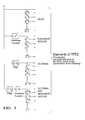
- FIG. 3is a process control flow diagram of the function generating the RTDL vector in the preferred method of the present invention.
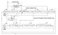
- FIG. 4is a process control flow diagram of the preferred method of the present invention.
- FIG. 2is a diagrammatic drawing of a hybrid vehicle 14 of the present invention.
- the hybrid vehicle 14includes a battery pack 16 having a single battery module or individual battery modules.
- the battery pack 16comprises a plurality of NiMH batteries connected in series to produce a 36 Volt nominal bus.
- the battery pack 16may comprise any known battery technology, including but not limited to lead acid and lithium polymer.
- a motor generator (MoGen) 20is dynamically coupled to an internal combustion engine (ICE) 22 and functions as either a motor to propel the vehicle 14 or a generator to charge the battery pack 16 , depending on the operating state of the vehicle 14 (i.e., braking, stopped, or operating at a constant speed on a highway).
- the MoGen 20is preferably an AC induction machine but may comprise any known electrical motor/generator technology, including, but not limited to, DC machines, synchronous machines, and switched reluctance machines.
- the MoGen 20 in the preferred embodimentis located on the rear of the vehicle to drive the rear wheels 17 .
- a similar MoGen 20is located on the front of the vehicle to drive the front wheels 18 .
- the MoGens 20are controlled by an electrical control system comprising a hybrid system controller 23 , DC—DC converters 24 and power inverter modules 25 .
- the controller 23 , DC—DC converters 24 , and power inverter modules 25may be configured as a unitary system.
- the hybrid system controller 23may comprise any type of control module or vehicle controller known in the art, and is equipped with nonvolatile memory (NVM), random access memory (RAM), discrete and analog input/output (I/O), a central processing unit, communications interfaces for conventional and wireless (Bluetooth®) networking within an automotive communications network, etc.
- NVMnonvolatile memory
- RAMrandom access memory
- I/Odiscrete and analog input/output
- central processing unitcommunications interfaces for conventional and wireless (Bluetooth®) networking within an automotive communications network, etc.
- the MoGens 20 in generator modegenerate electrical energy that is transferred to the battery pack 16 and the DC—DC converters 24 by the controller 23 and inverter modules 25 .
- the controller 23 and inverter modules 25determine the direction of current flow for the MoGens 20 , according to the vehicle 14 operating state.
- the DC—DC converters 24provide and regulate the DC bus that is pulse-width-modulated by the inverter modules 25 to supply time varying current to the MoGens 20 .
- a regeneration state(such as during braking) or charging condition
- currentwill flow from the MoGens 20 , via the inverter modules 25 , to charge the battery pack 16 and provide current to the DC—DC converters 24 .
- a state where the MoGens 20 are needed to provide propulsioncurrent will flow from the battery pack 16 to the MoGens 20 , via the DC—DC converters 24 and inverter modules 25 , to power the MoGens 20 .
- the SOC of the battery pack 16is dynamically tracked to determine when to charge the battery pack 16 .
- the hybrid controller 23 of the present inventionwill control a battery pack's SOC near 50% to 80% so that the charge acceptance and efficiency during regenerative braking can be realized, although controlling the battery pack 16 to any SOC percentage is within the scope of the present invention.
- the elements of the vectorare current values which are subjected to one or more of the following operations: delays in time, resampling, frequency filtering, linear scaling and nonlinear scaling, units of amps.
- T value of cell skin temperature at sample kunits of degrees Kelvin Ts sample time in seconds, nominal value of 1.00 U ⁇ pivot voltage in Nernst Equations, nominal value of 1.345 volts V value of cell terminal voltage at sample k, units of volts x ⁇ vector containing the states and parameter estimates of the battery prior to correction from the measurements [Q Q H ⁇ T ] T x + vector containing the states and parameter estimations of the battery after the correction from measurements [Q Q H ⁇ T ] T ⁇ rate of hysteresis charge change, nominal value of 1.6 hr ⁇ ratio of hysteresis charge to cell voltage, nominal value of 0.02222 V/amp-hr ⁇ reciprocal of amount of charge required to saturate hysteresis, nominal ⁇
- next_QQ+((I ⁇ (Q,T) ⁇ I SD (Q,T))/3600) ⁇ Ts
- next_x[next_Q next_Q H next_ ⁇ T ] T
- this functionreturns [ ( 1 + ⁇ ⁇ ⁇ ⁇ ⁇ ⁇ Q ⁇ ( I , Q , T ) ⁇ Ts ⁇ I 3600 - Ts ⁇ I SD ⁇ ( Q , T ) Q ⁇ 3600 ) 0 0 ( ⁇ ⁇ Ts ⁇ ( - I SD ⁇ ( Q , T ) Q ⁇ 3600 ) ⁇ Q H ⁇ ⁇ max ⁇ ( Q ) - Q H Q H ⁇ ⁇ max ⁇ ( Q ) ) ( 1 - ⁇ ⁇ I - I SD ⁇ ( Q , T ) 3600 ⁇ Ts ) 0 0 0 diag ⁇ ( 1 ) ]
- yh(x,u,RTDL)—a function which forms voltage estimate from states and currents
- dhdx(x,u,RTDL)a function which returns the Jacobian of h( ⁇ ) with respect to x
- ⁇ h ⁇ x[ ⁇ ⁇ Q ⁇ ⁇ ⁇ h ⁇ Q H ⁇ ⁇ ⁇ h ⁇ a T ]
- Q HVar (Q)process noise variance associated with propagation of the hysteresis estimate. This variance is associated with battery charge. All values are linearly interpolated.
- QtoV(Q,T)equation which converts charge and temperature to open circuit voltage using the Nernst equation.
- Qis in amp-hrs and T is in Kelvin
- fF N Rg ⁇ T
- SOCQ
- VU ⁇ + 1 f ⁇ log ⁇ ( SOC 1.0001 - SOC + 0.0001 ) , volts ⁇ ⁇ per ⁇ ⁇ cell
- ⁇ (Q,Q H ,I)process noise variance as a function of charge, hysteresis charge and current.
- ⁇[ Q Var ⁇ ( Q ) 0 0 0 ( Q HVar ⁇ ( Q ) + Q HVar ⁇ ( Q H , I ) ) 0 0 0 a Var ⁇ ( I ) ]
- the nominal value for this functionis 0.99.
- This inventionprovides a method to estimate the state, including but not limited to the SOC, temperature, and power of a battery that relies on two distinct steps: a prediction of the next battery response and a correction based on the differences (i.e., quality of the prediction) between the prediction and the measured response of the battery.
- the correctionis based on a statistically optimal method.
- the method of the present inventionin a first embodiment, produces a state vector which preferably comprises a state of charge estimate, Q, a hysteresis charge estimate, Q H , and a q ⁇ 1 vector of learned battery responses, ⁇ .
- the learned battery responsesare used to predict the terminal voltage that occurs under load.
- This dynamic voltageis formed by multiplying the learned battery response by a vector of current measurements which have been modified and time shifted.
- the first step in the preferred methodis initialization.
- an initial valueis selected for each of the state variables.
- a covariance matrixis initialized, P 0 .
- a vector that contains the current historyis also initialized to a set of values that represents the currents prior to initialization. This vector is referred to as resampled, tap delay line (RTDL).
- the RTDL vectorcan be expanded.
- the illustrated functionforms the elements of the RTDL vector in combination of the following:
- Recover x + from nonvolatile memoryRecover T from nonvolatile memory and store in oldT. Sample temperature and store in T.
- Recover RTDL from nonvolatile memoryCalculate the time in seconds since the last update of x + and store in t.
- x ⁇x + .
- P ⁇P + .
- II Parasitic Update RTDL using I.
- u[I ⁇ circumflex over (T) ⁇ ] T .
- Every iteration of the preferred methodcomprises one or more prediction steps.
- a prediction stepoccurs, three things happen.
- the nonlinear modelis linearized about the current state, then this linear model is used to propagate the covariance of the estimate.
- the nonlinear model of the methodis used to predict the next state the system.
- the modified current history vector(RTDL) is updated based on the current estimate.
- a simple embodiment of the modified current history vectoris a tap delay line.
- the input vector umay be based on a measurement of current, or carried forward from a previous measurement. With reference to the signal flow diagram of FIG. 4, the following prediction steps may be executed.
- Update the RTDL vector using uSee block 30 of FIG. 4 .
- Block 36generates a quality estimate of the state estimate before the correction step.
- Blocks 38 and 39represent unit time delays.
- a measurementis made of current and voltage. Based on a linearized model of the battery, about its present state estimate, the measurement correction is performed as follows.
- Blocks 46 and 48generate a quality estimate of the ?? after the correction steps.
- the present inventionfurther includes an acceptance and discharge capability predictor algorithm (i.e., power) that utilizes the SOC methods of the present invention.
- the SOC methodconstructs a model of the battery in the process of predicting SOC. This model can be used to predict the charge acceptance of the battery or the discharge capability of the battery.
- charge acceptanceis a measure of the amount of power that can be accepted by the battery until a defined voltage lid is reached.
- Discharge capabilityis defined as a measure of the amount of power that can be sourced by the battery until a defined voltage floor is reached.
- One measure of charge acceptanceis the amount of time that a fixed power level can be accepted or delivered by the battery. The following method will calculate this:
- V Lidthe highest voltage that can be sustained
- V Floorthe lowest voltage that can be sustained by executing the following:
Landscapes
- Physics & Mathematics (AREA)
- General Physics & Mathematics (AREA)
- Secondary Cells (AREA)
- Electric Propulsion And Braking For Vehicles (AREA)
Abstract
Description


| abs(I) | |||
| 0 | 0.0000055 | ||
| 1 | 0.0000060 | ||
| 5 | 0.0000100 | ||
| 25 | 0.0000250 | ||
| 100 | 0.0001000 | ||


| Q/Qmax | Variance | ||
| 0.0 | 0.00001 | ||
| 0.1 | 0.00010 | ||
| 0.2 | 0.00020 | ||
| 0.4 | 0.00030 | ||
| 0.5 | 0.00050 | ||
| 0.6 | 0.00030 | ||
| 0.8 | 0.00020 | ||
| 0.9 | 0.00010 | ||
| 1.0 | 0.00001 | ||
| QH/QH max inc(Q) | Variance | ||
| −1.0 | 0.050 | ||
| −0.8 | 0.050 | ||
| −0.6 | 0.050 | ||
| −0.4 | 0.050 | ||
| −0.2 | 0.050 | ||
| 0.0 | 0.050 | ||
| 0.2 | 0.050 | ||
| 0.4 | 0.040 | ||
| 0.6 | 0.030 | ||
| 0.8 | 0.020 | ||
| 1.0 | 0.001 | ||
| QH/QH max dec(Q) | Variance | ||
| −1.0 | 0.001 | ||
| −0.8 | 0.020 | ||
| −0.6 | 0.030 | ||
| −0.4 | 0.040 | ||
| −0.2 | 0.050 | ||
| 0.0 | 0.050 | ||
| 0.2 | 0.050 | ||
| 0.4 | 0.050 | ||
| 0.6 | 0.050 | ||
| 0.8 | 0.050 | ||
| 1.0 | 0.050 | ||

| Q/Qmax | Variance | ||
| 0.0 | 0.00002 | ||
| 0.2 | 0.00001 | ||
| 0.4 | 0.00001 | ||
| 0.5 | 0.00001 | ||
| 0.6 | 0.00001 | ||
| 0.8 | 0.00005 | ||
| 1.0 | 0.00010 | ||


| Recover x+from nonvolatile memory. |
| Recover T from nonvolatile memory and store in oldT. |
| Sample temperature and store in T. |
| Recover RTDL from nonvolatile memory. |
| Calculate the time in seconds since the last update of x+ and store in t. |

| model: x− = f (x−, u). |
| Linearize the model about the current operating point, let |
| F = dfdx(x−,u). |
| Get Q and QHfrom the x− vector. | ||
| Propagate the covariance estimate, Let P− = F · P− · FT+ φ(Q, Qh, I) | ||


Claims (21)
Priority Applications (4)
| Application Number | Priority Date | Filing Date | Title |
|---|---|---|---|
| US09/814,528US6441586B1 (en) | 2001-03-23 | 2001-03-23 | State of charge prediction method and apparatus for a battery |
| EP02001512AEP1243933B1 (en) | 2001-03-23 | 2002-01-22 | State of charge prediction method and apparatus for a battery |
| DE60231446TDE60231446D1 (en) | 2001-03-23 | 2002-01-22 | Prediction method for the state of charge and device for a battery |
| JP2002084095AJP4073228B2 (en) | 2001-03-23 | 2002-03-25 | Charge state prediction method and apparatus for battery |
Applications Claiming Priority (1)
| Application Number | Priority Date | Filing Date | Title |
|---|---|---|---|
| US09/814,528US6441586B1 (en) | 2001-03-23 | 2001-03-23 | State of charge prediction method and apparatus for a battery |
Publications (1)
| Publication Number | Publication Date |
|---|---|
| US6441586B1true US6441586B1 (en) | 2002-08-27 |
Family
ID=25215319
Family Applications (1)
| Application Number | Title | Priority Date | Filing Date |
|---|---|---|---|
| US09/814,528Expired - LifetimeUS6441586B1 (en) | 2001-03-23 | 2001-03-23 | State of charge prediction method and apparatus for a battery |
Country Status (4)
| Country | Link |
|---|---|
| US (1) | US6441586B1 (en) |
| EP (1) | EP1243933B1 (en) |
| JP (1) | JP4073228B2 (en) |
| DE (1) | DE60231446D1 (en) |
Cited By (112)
| Publication number | Priority date | Publication date | Assignee | Title |
|---|---|---|---|---|
| US20020169581A1 (en)* | 2001-02-13 | 2002-11-14 | Christel Sarfert | Method and device for state sensing of technical systems such as energy stores |
| US6515454B2 (en)* | 2001-02-13 | 2003-02-04 | Robert Bosch Gmbh | Method and system for determining the capacity of a battery |
| US20030231005A1 (en)* | 2002-03-18 | 2003-12-18 | Hirofumi Kohama | Battery control apparatus |
| US20040095143A1 (en)* | 2002-08-13 | 2004-05-20 | Vb Autobatterie Gmbh | Method for determining the amount of charge which can be drawn from a storage battery and a monitoring device for a storage battery |
| US20040113629A1 (en)* | 2002-07-26 | 2004-06-17 | Helmut Laig-Hoerstebrock | Energy store and method for determining the wear to an electrochemical energy store |
| US20040158418A1 (en)* | 2003-02-07 | 2004-08-12 | Espec Corp. | Battery state diagnosing device and battery state diagnosing method |
| US20050046388A1 (en)* | 2003-08-28 | 2005-03-03 | Tate Edward D. | Simple optimal estimator for PbA state of charge |
| US20050052810A1 (en)* | 2001-12-03 | 2005-03-10 | Teuvo Suntio | Method and apparatus for soft-sensor characterization of batteries |
| US20050057255A1 (en)* | 2003-09-17 | 2005-03-17 | Tate Edward D. | Generalized electrochemical cell state and parameter estimator |
| US20050168180A1 (en)* | 2002-05-14 | 2005-08-04 | Hideto Minekawa | Method and device for controlling fan for cooling vehicle-mounted battery |
| US6947855B2 (en) | 2003-08-07 | 2005-09-20 | General Motors Corporation | Adaptive algorithm to control and characterize super-capacitor performance |
| US20050231164A1 (en)* | 2004-04-06 | 2005-10-20 | Robert Melichar | State of charge tracking system for battery systems |
| US20050231165A1 (en)* | 2004-04-06 | 2005-10-20 | Robert Melichar | State of charge tracking system for battery systems based on relaxation voltage |
| US20050231166A1 (en)* | 2004-04-06 | 2005-10-20 | Robert Melichar | State of charge tracking system for battery systems based on relaxation voltage |
| US20050275407A1 (en)* | 2004-06-11 | 2005-12-15 | Nissan Motor Co., Ltd. | Available input-output power estimating device for secondary battery |
| US20060091861A1 (en)* | 2004-04-06 | 2006-05-04 | Cobasys, Llc | Battery state of charge reset |
| US20060100833A1 (en)* | 2004-11-11 | 2006-05-11 | Plett Gregory L | State and parameter estimation for an electrochemical cell |
| US20060125319A1 (en)* | 2004-12-15 | 2006-06-15 | King Robert D | System and method for providing power control of an energy storage system |
| WO2007024093A1 (en) | 2005-08-23 | 2007-03-01 | Lg Chem, Ltd. | System and method for estimating a state vector associated with a battery |
| US20070065713A1 (en)* | 2003-04-11 | 2007-03-22 | Lutz Rauchfuss | Method for detecting acid stratification in a battery |
| WO2007045673A1 (en)* | 2005-10-21 | 2007-04-26 | Robert Bosch Gmbh | Method for predicting the power capacity of an electrical energy store |
| WO2007064143A1 (en) | 2005-11-30 | 2007-06-07 | Lg Chem, Ltd. | System, method, and article of manufacture for determining an estimated battery parameter vector |
| WO2007100189A1 (en)* | 2006-03-02 | 2007-09-07 | Lg Chem, Ltd | System and method for determining both an estimated battery state vector and an estimated battery parameter vector |
| US7280301B1 (en)* | 2003-10-07 | 2007-10-09 | Maxtor Corporation | Temperature estimator for electronic device |
| US20080094035A1 (en)* | 2003-11-20 | 2008-04-24 | Lg Chem Ltd. | Method for calculating power capability of battery packs using advanced cell model predictive techniques |
| US20080249726A1 (en)* | 2006-02-09 | 2008-10-09 | Lg Twin Towers 20 | System, method, and article of manufacture for determining an estimated combined battery state-parameter vector |
| US20090009183A1 (en)* | 2007-07-05 | 2009-01-08 | Mousavi Mirrasoul J | System and method for predictive maintenance of a battery assembly using temporal signal processing |
| US20090030627A1 (en)* | 2005-11-10 | 2009-01-29 | Lg Chem, Ltd. | System, method, and article of manufacture for determining an estimated battery state vector |
| US20090027007A1 (en)* | 2006-01-12 | 2009-01-29 | The Furukawa Electric Co, Ltd. | Method and device for determining battery discharge capability, and power supply system |
| US20090186265A1 (en)* | 2008-01-18 | 2009-07-23 | Lg Chem, Ltd | Battery cell assembly and method for assembling the battery cell assembly |
| US20090189613A1 (en)* | 2008-01-30 | 2009-07-30 | Lg Chem Ltd. | System, method, and article of manufacture for determining an estimated battery cell module state |
| US20090210179A1 (en)* | 2008-02-19 | 2009-08-20 | Gm Global Technology Operations, Inc. | Model-based estimation of battery hysteresis |
| US20090325059A1 (en)* | 2008-06-30 | 2009-12-31 | Lg Chem, Ltd. | Battery Module Having Battery Cell Assemblies With Alignment-Coupling Features |
| US20090325052A1 (en)* | 2008-06-30 | 2009-12-31 | Lg Chem, Ltd. | Battery Module Having Cooling Manifold and Method for Cooling Battery Module |
| US20090325053A1 (en)* | 2008-06-30 | 2009-12-31 | Lg Chem, Ltd. | Battery Module Having Battery Cell Assembly with Heat Exchanger |
| US20090325051A1 (en)* | 2008-06-30 | 2009-12-31 | Lg Chem, Ltd. | Battery Module Having a Rubber Cooling Manifold |
| US20090325054A1 (en)* | 2008-06-30 | 2009-12-31 | Lg Chem, Ltd. | Battery Cell Assembly Having Heat Exchanger With Serpentine Flow Path |
| US20090325055A1 (en)* | 2008-06-30 | 2009-12-31 | Lg Chem, Ltd. | Battery module having cooling manifold with ported screws and method for cooling the battery module |
| US20100076705A1 (en)* | 2008-09-25 | 2010-03-25 | Gm Global Technology Operations, Inc. | Method and system for determining a state of charge of a battery based on a transient response |
| FR2941053A1 (en)* | 2009-01-15 | 2010-07-16 | Peugeot Citroen Automobiles Sa | Device for estimating charge state of battery of motor vehicle e.g. car, has calculating unit estimating charge state of battery based on voltage correspondence table of deduced off-load voltage/ charge state |
| US20100225325A1 (en)* | 2009-03-03 | 2010-09-09 | Robert Bosch Gmbh | Battery System and Method for System State of Charge Determination |
| US20100266883A1 (en)* | 2009-04-20 | 2010-10-21 | Lg Chem, Ltd. | Frame member, frame assembly and battery cell assembly made therefrom and methods of making the same |
| US20100276132A1 (en)* | 2009-04-30 | 2010-11-04 | Lg Chem, Ltd. | Cooling manifold and method for manufacturing the cooling manifold |
| US20100279152A1 (en)* | 2009-04-30 | 2010-11-04 | Lg Chem, Ltd. | Battery systems, battery modules, and method for cooling a battery module |
| US20100279153A1 (en)* | 2009-04-30 | 2010-11-04 | Lg Chem, Ltd. | Battery systems, battery module, and method for cooling the battery module |
| US20100275619A1 (en)* | 2009-04-30 | 2010-11-04 | Lg Chem, Ltd. | Cooling system for a battery system and a method for cooling the battery system |
| US20100279154A1 (en)* | 2009-04-30 | 2010-11-04 | Lg Chem, Ltd. | Battery systems, battery modules, and method for cooling a battery module |
| US7868592B2 (en) | 2007-12-10 | 2011-01-11 | Visteon Global Technologies, Inc. | Method of automotive electrical bus management |
| US20110027625A1 (en)* | 2009-07-29 | 2011-02-03 | Lg Chem, Ltd. | Battery module and method for cooling the battery module |
| US20110027640A1 (en)* | 2009-07-29 | 2011-02-03 | Lg Chem, Ltd. | Battery module and method for cooling the battery module |
| US20110031938A1 (en)* | 2009-08-04 | 2011-02-10 | Yosuke Ishikawa | Method of Estimating Battery State of Charge |
| US20110052959A1 (en)* | 2009-08-28 | 2011-03-03 | Lg Chem, Ltd. | Battery module and method for cooling the battery module |
| US20110226559A1 (en)* | 2008-11-17 | 2011-09-22 | Otis Elevator Company | Battery state-of-charge calibration |
| DE102010003421A1 (en)* | 2010-03-30 | 2011-10-06 | Bayerische Motoren Werke Aktiengesellschaft | Energy storage device operating method for e.g. hybrid car, involves determining initial sizes of energy storage voltage and current, determining two state of charge, and determining state of charge loss dependent on two state of charge |
| CN102289535A (en)* | 2011-06-07 | 2011-12-21 | 北京航空航天大学 | Spacecraft power system energy analysis simulation platform |
| EP2400313A1 (en)* | 2010-06-17 | 2011-12-28 | Volvo Car Corporation | Method and arrangement for ensuring sufficient electrical power supply for different electrically powered vehicle systems |
| US8202645B2 (en) | 2008-10-06 | 2012-06-19 | Lg Chem, Ltd. | Battery cell assembly and method for assembling the battery cell assembly |
| US20120179435A1 (en)* | 2011-01-10 | 2012-07-12 | Ford Global Technologies, Llc | Method For Determining A Power Capability For A Battery |
| US20120200298A1 (en)* | 2011-02-09 | 2012-08-09 | GM Global Technology Operations LLC | Automotive Battery SOC Estimation Based on Voltage Decay |
| US8288031B1 (en) | 2011-03-28 | 2012-10-16 | Lg Chem, Ltd. | Battery disconnect unit and method of assembling the battery disconnect unit |
| WO2012098523A3 (en)* | 2011-01-19 | 2012-11-15 | Sendyne Corp. | Converging algorithm for real-time battery prediction |
| US8341449B2 (en) | 2010-04-16 | 2012-12-25 | Lg Chem, Ltd. | Battery management system and method for transferring data within the battery management system |
| US8353315B2 (en) | 2010-08-23 | 2013-01-15 | Lg Chem, Ltd. | End cap |
| DE102011079469A1 (en) | 2011-07-20 | 2013-01-24 | Ford Global Technologies, Llc | Method for determining charge acceptance and method for charging a rechargeable battery |
| US8368357B2 (en) | 2010-06-24 | 2013-02-05 | Qnovo Inc. | Method and circuitry to adaptively charge a battery/cell |
| US20130099752A1 (en)* | 2011-10-25 | 2013-04-25 | Kia Motors Corporation | Battery system for protecting battery management system from electromagnetic waves |
| US20130119921A1 (en)* | 2011-11-14 | 2013-05-16 | Auburn University | Rapid battery charging method and system |
| US8449998B2 (en) | 2011-04-25 | 2013-05-28 | Lg Chem, Ltd. | Battery system and method for increasing an operational life of a battery cell |
| CN103135065A (en)* | 2013-01-25 | 2013-06-05 | 文创太阳能(福建)科技有限公司 | Iron phosphate lithium battery electric quantity detecting method based on feature points |
| US8469404B2 (en) | 2010-08-23 | 2013-06-25 | Lg Chem, Ltd. | Connecting assembly |
| US20130300190A1 (en)* | 2012-05-08 | 2013-11-14 | GM Global Technology Operations LLC | Battery state-of-charge observer |
| US8638070B2 (en) | 2010-05-21 | 2014-01-28 | Qnovo Inc. | Method and circuitry to adaptively charge a battery/cell |
| US8662153B2 (en) | 2010-10-04 | 2014-03-04 | Lg Chem, Ltd. | Battery cell assembly, heat exchanger, and method for manufacturing the heat exchanger |
| US8712595B2 (en) | 2011-01-18 | 2014-04-29 | General Electric Company | Dynamic load profiling in a power network |
| US8758922B2 (en) | 2010-08-23 | 2014-06-24 | Lg Chem, Ltd. | Battery system and manifold assembly with two manifold members removably coupled together |
| US20140244225A1 (en)* | 2013-02-24 | 2014-08-28 | The University Of Connecticut | Battery state of charge tracking, equivalent circuit selection and benchmarking |
| US8859119B2 (en) | 2011-06-30 | 2014-10-14 | Lg Chem, Ltd. | Heating system for a battery module and method of heating the battery module |
| US8872518B2 (en) | 2010-06-25 | 2014-10-28 | Atieva, Inc. | Determining the state of-charge of batteries via selective sampling of extrapolated open circuit voltage |
| US8880253B2 (en) | 2011-06-28 | 2014-11-04 | Ford Global Technologies, Llc | Nonlinear adaptive observation approach to battery state of charge estimation |
| US8920956B2 (en) | 2010-08-23 | 2014-12-30 | Lg Chem, Ltd. | Battery system and manifold assembly having a manifold member and a connecting fitting |
| US8970178B2 (en) | 2010-06-24 | 2015-03-03 | Qnovo Inc. | Method and circuitry to calculate the state of charge of a battery/cell |
| US8974928B2 (en) | 2011-06-30 | 2015-03-10 | Lg Chem, Ltd. | Heating system for a battery module and method of heating the battery module |
| US8974929B2 (en) | 2011-06-30 | 2015-03-10 | Lg Chem, Ltd. | Heating system for a battery module and method of heating the battery module |
| US8993136B2 (en) | 2011-06-30 | 2015-03-31 | Lg Chem, Ltd. | Heating system for a battery module and method of heating the battery module |
| US9005799B2 (en) | 2010-08-25 | 2015-04-14 | Lg Chem, Ltd. | Battery module and methods for bonding cell terminals of battery cells together |
| US9063018B1 (en) | 2012-10-22 | 2015-06-23 | Qnovo Inc. | Method and circuitry to determine temperature and/or state of health of a battery/cell |
| US9142994B2 (en) | 2012-09-25 | 2015-09-22 | Qnovo, Inc. | Method and circuitry to adaptively charge a battery/cell |
| US9147916B2 (en) | 2010-04-17 | 2015-09-29 | Lg Chem, Ltd. | Battery cell assemblies |
| US9178192B2 (en) | 2011-05-13 | 2015-11-03 | Lg Chem, Ltd. | Battery module and method for manufacturing the battery module |
| WO2016083753A1 (en) | 2014-11-28 | 2016-06-02 | Renault S.A.S. | Automatic method of estimating the charge state of a battery cell |
| US9461492B1 (en) | 2013-04-19 | 2016-10-04 | Qnovo Inc. | Method and circuitry to adaptively charge a battery/cell using a charge-time parameter |
| US20160306342A1 (en)* | 2015-04-17 | 2016-10-20 | Lsis Co., Ltd. | Communication system and operating method thereof |
| US9496544B2 (en) | 2011-07-28 | 2016-11-15 | Lg Chem. Ltd. | Battery modules having interconnect members with vibration dampening portions |
| US9555718B2 (en) | 2013-12-06 | 2017-01-31 | Ford Global Technologies, Llc | Estimation and compensation of battery measurement and asynchronization biases |
| US9658291B1 (en)* | 2012-10-06 | 2017-05-23 | Hrl Laboratories, Llc | Methods and apparatus for dynamic estimation of battery open-circuit voltage |
| US20170338667A1 (en)* | 2016-05-23 | 2017-11-23 | Nxp B.V. | Model-based fast-charging method based on lithium surface concentration |
| US9928938B2 (en) | 2015-02-10 | 2018-03-27 | Lisle Corporation | Parasitic battery drain test assembly for multiple component vehicle circuitry analysis |
| US9987942B2 (en)* | 2014-09-03 | 2018-06-05 | Ford Global Technologies, Llc | Method of operating vehicle powertrain based on prediction of how different chemical type batteries connected in parallel will operate to output demanded current |
| US9989595B1 (en)* | 2013-12-31 | 2018-06-05 | Hrl Laboratories, Llc | Methods for on-line, high-accuracy estimation of battery state of power |
| US10067198B2 (en) | 2010-05-21 | 2018-09-04 | Qnovo Inc. | Method and circuitry to adaptively charge a battery/cell using the state of health thereof |
| US10234512B2 (en) | 2011-06-11 | 2019-03-19 | Sendyne Corporation | Current-based cell modeling |
| US10338149B2 (en)* | 2016-10-13 | 2019-07-02 | Contemporary Amperex Technology Co., Limited | Method and apparatus for calculating SOC of a battery being charged and battery pack including the apparatus |
| US10389156B2 (en) | 2010-05-21 | 2019-08-20 | Qnovo Inc. | Method and circuitry to adaptively charge a battery/cell |
| US10451678B2 (en) | 2014-07-17 | 2019-10-22 | Ford Global Technologies, Llc | Battery system identification through impulse injection |
| CN110573893A (en)* | 2017-10-10 | 2019-12-13 | 株式会社Lg化学 | Apparatus and method for estimating state of charge of secondary battery |
| US10574079B1 (en) | 2014-06-20 | 2020-02-25 | Qnovo Inc. | Wireless charging techniques and circuitry for a battery |
| US20200175212A1 (en)* | 2017-02-21 | 2020-06-04 | Shandong University | FRACTIONAL-ORDER KiBaM BATTERY MODEL CONSIDERING NONLINEAR CAPACITY CHARACTERISTICS AND PARAMETER IDENTIFICATION METHOD |
| US11040624B2 (en) | 2014-10-15 | 2021-06-22 | Cps Technology Holdings Llc | Cooling strategy for battery systems |
| US11397215B2 (en) | 2010-05-21 | 2022-07-26 | Qnovo Inc. | Battery adaptive charging using battery physical phenomena |
| US11397216B2 (en) | 2010-05-21 | 2022-07-26 | Qnovo Inc. | Battery adaptive charging using a battery model |
| US11791647B2 (en) | 2010-05-21 | 2023-10-17 | Qnovo Inc. | Method and circuitry to adaptively charge a battery/cell |
| US12081057B2 (en) | 2010-05-21 | 2024-09-03 | Qnovo Inc. | Method and circuitry to adaptively charge a battery/cell |
Families Citing this family (8)
| Publication number | Priority date | Publication date | Assignee | Title |
|---|---|---|---|---|
| US7076350B2 (en)* | 2003-12-19 | 2006-07-11 | Lear Corporation | Vehicle energy management system using prognostics |
| US7525285B2 (en)* | 2004-11-11 | 2009-04-28 | Lg Chem, Ltd. | Method and system for cell equalization using state of charge |
| CN101067644B (en)* | 2007-04-20 | 2010-05-26 | 杭州高特电子设备有限公司 | Storage battery performance analytical expert diagnosing method |
| JP5875037B2 (en) | 2011-07-08 | 2016-03-02 | インターナショナル・ビジネス・マシーンズ・コーポレーションInternational Business Machines Corporation | Battery state prediction system, method and program |
| JP5852399B2 (en)* | 2011-10-17 | 2016-02-03 | インターナショナル・ビジネス・マシーンズ・コーポレーションInternational Business Machines Corporation | Battery state prediction system, method and program |
| JP5892182B2 (en)* | 2014-01-09 | 2016-03-23 | トヨタ自動車株式会社 | Vehicle power supply |
| JP6455914B2 (en)* | 2014-05-27 | 2019-01-23 | 学校法人立命館 | Storage power remaining amount estimation device, method for estimating remaining power storage amount of storage battery, and computer program |
| CN110208704B (en)* | 2019-04-29 | 2021-08-06 | 北京航空航天大学 | A lithium battery modeling method and system based on voltage hysteresis effect |
Citations (3)
| Publication number | Priority date | Publication date | Assignee | Title |
|---|---|---|---|---|
| US5570087A (en)* | 1994-02-18 | 1996-10-29 | Lemelson; Jerome H. | Motor vehicle performance monitor and method |
| US5714866A (en)* | 1994-09-08 | 1998-02-03 | National Semiconductor Corporation | Method and apparatus for fast battery charging using neural network fuzzy logic based control |
| US6329793B1 (en)* | 1996-07-29 | 2001-12-11 | Midtronics, Inc. | Method and apparatus for charging a battery |
Family Cites Families (2)
| Publication number | Priority date | Publication date | Assignee | Title |
|---|---|---|---|---|
| US6157169A (en)* | 1997-04-30 | 2000-12-05 | Samsung Electronics Co., Ltd. | Monitoring technique for accurately determining residual capacity of a battery |
| US5936383A (en)* | 1998-04-02 | 1999-08-10 | Lucent Technologies, Inc. | Self-correcting and adjustable method and apparatus for predicting the remaining capacity and reserve time of a battery on discharge |
- 2001
- 2001-03-23USUS09/814,528patent/US6441586B1/ennot_activeExpired - Lifetime
- 2002
- 2002-01-22EPEP02001512Apatent/EP1243933B1/ennot_activeExpired - Lifetime
- 2002-01-22DEDE60231446Tpatent/DE60231446D1/ennot_activeExpired - Lifetime
- 2002-03-25JPJP2002084095Apatent/JP4073228B2/ennot_activeExpired - Fee Related
Patent Citations (3)
| Publication number | Priority date | Publication date | Assignee | Title |
|---|---|---|---|---|
| US5570087A (en)* | 1994-02-18 | 1996-10-29 | Lemelson; Jerome H. | Motor vehicle performance monitor and method |
| US5714866A (en)* | 1994-09-08 | 1998-02-03 | National Semiconductor Corporation | Method and apparatus for fast battery charging using neural network fuzzy logic based control |
| US6329793B1 (en)* | 1996-07-29 | 2001-12-11 | Midtronics, Inc. | Method and apparatus for charging a battery |
Cited By (209)
| Publication number | Priority date | Publication date | Assignee | Title |
|---|---|---|---|---|
| US6515454B2 (en)* | 2001-02-13 | 2003-02-04 | Robert Bosch Gmbh | Method and system for determining the capacity of a battery |
| US20020169581A1 (en)* | 2001-02-13 | 2002-11-14 | Christel Sarfert | Method and device for state sensing of technical systems such as energy stores |
| US6829562B2 (en)* | 2001-02-13 | 2004-12-07 | Robert Bosch Gmbh | Method and device for state sensing of technical systems such as energy stores |
| US7711538B2 (en)* | 2001-12-03 | 2010-05-04 | Teuvo Suntio | Method and apparatus for soft-sensor characterization of batteries |
| US20050052810A1 (en)* | 2001-12-03 | 2005-03-10 | Teuvo Suntio | Method and apparatus for soft-sensor characterization of batteries |
| US20030231005A1 (en)* | 2002-03-18 | 2003-12-18 | Hirofumi Kohama | Battery control apparatus |
| US7015676B2 (en)* | 2002-03-18 | 2006-03-21 | Mitsubishi Jidosha Kogyo Kabushiki Kaisha | Battery control apparatus |
| US20050168180A1 (en)* | 2002-05-14 | 2005-08-04 | Hideto Minekawa | Method and device for controlling fan for cooling vehicle-mounted battery |
| US7348741B2 (en)* | 2002-05-14 | 2008-03-25 | Toyota Jidosha Kabushiki Kaisha | Method and device for controlling fan for cooling vehicle-mounted battery |
| US20040113629A1 (en)* | 2002-07-26 | 2004-06-17 | Helmut Laig-Hoerstebrock | Energy store and method for determining the wear to an electrochemical energy store |
| US6949911B2 (en)* | 2002-08-13 | 2005-09-27 | Vb Autobatterie Gmbh | Method for determining the amount of charge which can be drawn from a storage battery and a monitoring device for a storage battery |
| US20040095143A1 (en)* | 2002-08-13 | 2004-05-20 | Vb Autobatterie Gmbh | Method for determining the amount of charge which can be drawn from a storage battery and a monitoring device for a storage battery |
| US20040158418A1 (en)* | 2003-02-07 | 2004-08-12 | Espec Corp. | Battery state diagnosing device and battery state diagnosing method |
| US7216044B2 (en)* | 2003-02-07 | 2007-05-08 | Espec Corporation | Battery state diagnosing device and battery state diagnosing method |
| US7701175B2 (en)* | 2003-04-11 | 2010-04-20 | Robert Bosch Gmbh | Method for detecting acid stratification in a battery |
| US20070065713A1 (en)* | 2003-04-11 | 2007-03-22 | Lutz Rauchfuss | Method for detecting acid stratification in a battery |
| US6947855B2 (en) | 2003-08-07 | 2005-09-20 | General Motors Corporation | Adaptive algorithm to control and characterize super-capacitor performance |
| US6927554B2 (en)* | 2003-08-28 | 2005-08-09 | General Motors Corporation | Simple optimal estimator for PbA state of charge |
| US20050046388A1 (en)* | 2003-08-28 | 2005-03-03 | Tate Edward D. | Simple optimal estimator for PbA state of charge |
| US7109685B2 (en)* | 2003-09-17 | 2006-09-19 | General Motors Corporation | Method for estimating states and parameters of an electrochemical cell |
| US20050057255A1 (en)* | 2003-09-17 | 2005-03-17 | Tate Edward D. | Generalized electrochemical cell state and parameter estimator |
| US7280301B1 (en)* | 2003-10-07 | 2007-10-09 | Maxtor Corporation | Temperature estimator for electronic device |
| US20100174500A1 (en)* | 2003-11-20 | 2010-07-08 | Lg Chem Ltd. | Method for calculating power capability of battery packs using advanced cell model predictive techniques |
| US7969120B2 (en) | 2003-11-20 | 2011-06-28 | Lg Chem, Ltd. | Method for calculating power capability of battery packs using advanced cell model predictive techniques |
| US20080094035A1 (en)* | 2003-11-20 | 2008-04-24 | Lg Chem Ltd. | Method for calculating power capability of battery packs using advanced cell model predictive techniques |
| US7453238B2 (en) | 2004-04-06 | 2008-11-18 | Cobasys, Llc | State of charge tracking system for battery systems based on relaxation voltage |
| US20060091861A1 (en)* | 2004-04-06 | 2006-05-04 | Cobasys, Llc | Battery state of charge reset |
| US8427109B2 (en) | 2004-04-06 | 2013-04-23 | Chevron Technology Ventures Llc | Battery state of charge reset |
| US20050231166A1 (en)* | 2004-04-06 | 2005-10-20 | Robert Melichar | State of charge tracking system for battery systems based on relaxation voltage |
| US8878539B2 (en) | 2004-04-06 | 2014-11-04 | Robert Bosch Gmbh | State of charge tracking system for battery systems based on relaxation voltage |
| US20050231164A1 (en)* | 2004-04-06 | 2005-10-20 | Robert Melichar | State of charge tracking system for battery systems |
| US20050231165A1 (en)* | 2004-04-06 | 2005-10-20 | Robert Melichar | State of charge tracking system for battery systems based on relaxation voltage |
| US7375497B2 (en) | 2004-04-06 | 2008-05-20 | Cobasys, Llc | State of charge tracking system for battery systems |
| US20050275407A1 (en)* | 2004-06-11 | 2005-12-15 | Nissan Motor Co., Ltd. | Available input-output power estimating device for secondary battery |
| US7486079B2 (en)* | 2004-06-11 | 2009-02-03 | Nissan Motor Co., Ltd. | Available input-output power estimating device for secondary battery |
| US8103485B2 (en)* | 2004-11-11 | 2012-01-24 | Lg Chem, Ltd. | State and parameter estimation for an electrochemical cell |
| US20060100833A1 (en)* | 2004-11-11 | 2006-05-11 | Plett Gregory L | State and parameter estimation for an electrochemical cell |
| US7960855B2 (en)* | 2004-12-15 | 2011-06-14 | General Electric Company | System and method for providing power control of an energy storage system |
| US20060125319A1 (en)* | 2004-12-15 | 2006-06-15 | King Robert D | System and method for providing power control of an energy storage system |
| EP1917536A4 (en)* | 2005-08-23 | 2017-08-23 | LG Chem, Ltd. | System and method for estimating a state vector associated with a battery |
| CN101248365B (en)* | 2005-08-23 | 2010-11-10 | Lg化学株式会社 | System and method for estimating a state vector associated with a battery |
| US7800375B2 (en) | 2005-08-23 | 2010-09-21 | Lg Chem, Ltd. | System and method for estimating a state vector associated with a battery |
| WO2007024093A1 (en) | 2005-08-23 | 2007-03-01 | Lg Chem, Ltd. | System and method for estimating a state vector associated with a battery |
| KR100952049B1 (en)* | 2005-08-23 | 2010-04-07 | 주식회사 엘지화학 | System and method for estimating a state vector associated with a battery |
| US20090261837A1 (en)* | 2005-08-23 | 2009-10-22 | Lg Chem, Ltd. | System and method for estimating a state vector associated with a battery |
| WO2007045673A1 (en)* | 2005-10-21 | 2007-04-26 | Robert Bosch Gmbh | Method for predicting the power capacity of an electrical energy store |
| US20090306915A1 (en)* | 2005-10-21 | 2009-12-10 | Eberhard Schoch | Method for predicting the power capacity of electrical energy stores |
| US7884613B2 (en)* | 2005-11-10 | 2011-02-08 | Lg Chem, Ltd. | System, method, and article of manufacture for determining an estimated battery state vector |
| CN101305509B (en)* | 2005-11-10 | 2010-12-29 | Lg化学株式会社 | System and method for determining an estimated battery state vector |
| US20090030627A1 (en)* | 2005-11-10 | 2009-01-29 | Lg Chem, Ltd. | System, method, and article of manufacture for determining an estimated battery state vector |
| US20100191491A1 (en)* | 2005-11-30 | 2010-07-29 | Lg Chem, Ltd. | System, method, and article of manufacture for determining an estimated battery parameter vector |
| CN101322039B (en)* | 2005-11-30 | 2011-04-06 | Lg化学株式会社 | System, method, and article of manufacture for determining an estimated battery parameter vector |
| WO2007064143A1 (en) | 2005-11-30 | 2007-06-07 | Lg Chem, Ltd. | System, method, and article of manufacture for determining an estimated battery parameter vector |
| EP1971872A4 (en)* | 2005-11-30 | 2017-08-23 | LG Chem, Ltd. | System, method, and article of manufacture for determining an estimated battery parameter vector |
| US7965059B2 (en) | 2005-11-30 | 2011-06-21 | Lg Chem, Ltd. | System, method, and article of manufacture for determining an estimated battery parameter vector |
| KR101355958B1 (en)* | 2005-11-30 | 2014-02-11 | 주식회사 엘지화학 | System, method and article of manufacture for determining an estimated battery parameter vector |
| US7764049B2 (en)* | 2006-01-12 | 2010-07-27 | The Furukawa Electric Co., Ltd. | Method and device for determining battery discharge capability, and power supply system |
| US20090027007A1 (en)* | 2006-01-12 | 2009-01-29 | The Furukawa Electric Co, Ltd. | Method and device for determining battery discharge capability, and power supply system |
| US20080249726A1 (en)* | 2006-02-09 | 2008-10-09 | Lg Twin Towers 20 | System, method, and article of manufacture for determining an estimated combined battery state-parameter vector |
| US7893694B2 (en)* | 2006-02-09 | 2011-02-22 | Lg Chem, Ltd. | System, method, and article of manufacture for determining an estimated combined battery state-parameter vector |
| EP3264562A1 (en)* | 2006-02-09 | 2018-01-03 | Lg Chem, Ltd. | System, method, and article of manufacture for determining an estimated combined battery state-parameter vector |
| KR101355959B1 (en)* | 2006-03-02 | 2014-02-03 | 주식회사 엘지화학 | System and method for determining both an estimated battery state vector and an estimated battery parameter vector |
| WO2007100189A1 (en)* | 2006-03-02 | 2007-09-07 | Lg Chem, Ltd | System and method for determining both an estimated battery state vector and an estimated battery parameter vector |
| CN101395489B (en)* | 2006-03-02 | 2011-11-02 | 株式会社Lg化学 | Systems and methods for determining an estimated battery state vector and an estimated battery parameter vector |
| US8154297B2 (en) | 2007-07-05 | 2012-04-10 | Abb Technology Ag | System and method for predictive maintenance of a battery assembly using temporal signal processing |
| US20090009183A1 (en)* | 2007-07-05 | 2009-01-08 | Mousavi Mirrasoul J | System and method for predictive maintenance of a battery assembly using temporal signal processing |
| US7868592B2 (en) | 2007-12-10 | 2011-01-11 | Visteon Global Technologies, Inc. | Method of automotive electrical bus management |
| US20090186265A1 (en)* | 2008-01-18 | 2009-07-23 | Lg Chem, Ltd | Battery cell assembly and method for assembling the battery cell assembly |
| US8628872B2 (en) | 2008-01-18 | 2014-01-14 | Lg Chem, Ltd. | Battery cell assembly and method for assembling the battery cell assembly |
| US7994755B2 (en)* | 2008-01-30 | 2011-08-09 | Lg Chem, Ltd. | System, method, and article of manufacture for determining an estimated battery cell module state |
| US8519675B2 (en) | 2008-01-30 | 2013-08-27 | Lg Chem, Ltd. | System, method, and article of manufacture for determining an estimated battery cell module state |
| US20090189613A1 (en)* | 2008-01-30 | 2009-07-30 | Lg Chem Ltd. | System, method, and article of manufacture for determining an estimated battery cell module state |
| US7957921B2 (en)* | 2008-02-19 | 2011-06-07 | GM Global Technology Operations LLC | Model-based estimation of battery hysteresis |
| CN101946187A (en)* | 2008-02-19 | 2011-01-12 | 通用汽车环球科技运作公司 | Battery hysteresis based on model is estimated |
| CN101946187B (en)* | 2008-02-19 | 2013-06-19 | 通用汽车环球科技运作公司 | Model-based battery hysteresis estimation |
| WO2009108494A1 (en)* | 2008-02-19 | 2009-09-03 | Gm Global Technology Operations, Inc. | Model-based estimation of battery hysteresis |
| US20090210179A1 (en)* | 2008-02-19 | 2009-08-20 | Gm Global Technology Operations, Inc. | Model-based estimation of battery hysteresis |
| US9759495B2 (en) | 2008-06-30 | 2017-09-12 | Lg Chem, Ltd. | Battery cell assembly having heat exchanger with serpentine flow path |
| US20090325059A1 (en)* | 2008-06-30 | 2009-12-31 | Lg Chem, Ltd. | Battery Module Having Battery Cell Assemblies With Alignment-Coupling Features |
| US20090325054A1 (en)* | 2008-06-30 | 2009-12-31 | Lg Chem, Ltd. | Battery Cell Assembly Having Heat Exchanger With Serpentine Flow Path |
| US7883793B2 (en) | 2008-06-30 | 2011-02-08 | Lg Chem, Ltd. | Battery module having battery cell assemblies with alignment-coupling features |
| US20090325055A1 (en)* | 2008-06-30 | 2009-12-31 | Lg Chem, Ltd. | Battery module having cooling manifold with ported screws and method for cooling the battery module |
| US20090325053A1 (en)* | 2008-06-30 | 2009-12-31 | Lg Chem, Ltd. | Battery Module Having Battery Cell Assembly with Heat Exchanger |
| US8426050B2 (en) | 2008-06-30 | 2013-04-23 | Lg Chem, Ltd. | Battery module having cooling manifold and method for cooling battery module |
| US20090325052A1 (en)* | 2008-06-30 | 2009-12-31 | Lg Chem, Ltd. | Battery Module Having Cooling Manifold and Method for Cooling Battery Module |
| US20090325051A1 (en)* | 2008-06-30 | 2009-12-31 | Lg Chem, Ltd. | Battery Module Having a Rubber Cooling Manifold |
| US9140501B2 (en) | 2008-06-30 | 2015-09-22 | Lg Chem, Ltd. | Battery module having a rubber cooling manifold |
| US8067111B2 (en) | 2008-06-30 | 2011-11-29 | Lg Chem, Ltd. | Battery module having battery cell assembly with heat exchanger |
| US20100076705A1 (en)* | 2008-09-25 | 2010-03-25 | Gm Global Technology Operations, Inc. | Method and system for determining a state of charge of a battery based on a transient response |
| US8321164B2 (en)* | 2008-09-25 | 2012-11-27 | GM Global Technology Operations LLC | Method and system for determining a state of charge of a battery based on a transient response |
| US8202645B2 (en) | 2008-10-06 | 2012-06-19 | Lg Chem, Ltd. | Battery cell assembly and method for assembling the battery cell assembly |
| US20110226559A1 (en)* | 2008-11-17 | 2011-09-22 | Otis Elevator Company | Battery state-of-charge calibration |
| US8887872B2 (en) | 2008-11-17 | 2014-11-18 | Otis Elevator Company | Method of determining state of charge of energy storage system |
| FR2941053A1 (en)* | 2009-01-15 | 2010-07-16 | Peugeot Citroen Automobiles Sa | Device for estimating charge state of battery of motor vehicle e.g. car, has calculating unit estimating charge state of battery based on voltage correspondence table of deduced off-load voltage/ charge state |
| US9030169B2 (en)* | 2009-03-03 | 2015-05-12 | Robert Bosch Gmbh | Battery system and method for system state of charge determination |
| US20100225325A1 (en)* | 2009-03-03 | 2010-09-09 | Robert Bosch Gmbh | Battery System and Method for System State of Charge Determination |
| US9337456B2 (en) | 2009-04-20 | 2016-05-10 | Lg Chem, Ltd. | Frame member, frame assembly and battery cell assembly made therefrom and methods of making the same |
| US20100266883A1 (en)* | 2009-04-20 | 2010-10-21 | Lg Chem, Ltd. | Frame member, frame assembly and battery cell assembly made therefrom and methods of making the same |
| US8663829B2 (en) | 2009-04-30 | 2014-03-04 | Lg Chem, Ltd. | Battery systems, battery modules, and method for cooling a battery module |
| US8663828B2 (en) | 2009-04-30 | 2014-03-04 | Lg Chem, Ltd. | Battery systems, battery module, and method for cooling the battery module |
| US8852778B2 (en) | 2009-04-30 | 2014-10-07 | Lg Chem, Ltd. | Battery systems, battery modules, and method for cooling a battery module |
| US20100275619A1 (en)* | 2009-04-30 | 2010-11-04 | Lg Chem, Ltd. | Cooling system for a battery system and a method for cooling the battery system |
| US20100276132A1 (en)* | 2009-04-30 | 2010-11-04 | Lg Chem, Ltd. | Cooling manifold and method for manufacturing the cooling manifold |
| US20100279152A1 (en)* | 2009-04-30 | 2010-11-04 | Lg Chem, Ltd. | Battery systems, battery modules, and method for cooling a battery module |
| US20100279153A1 (en)* | 2009-04-30 | 2010-11-04 | Lg Chem, Ltd. | Battery systems, battery module, and method for cooling the battery module |
| US8403030B2 (en) | 2009-04-30 | 2013-03-26 | Lg Chem, Ltd. | Cooling manifold |
| US20100279154A1 (en)* | 2009-04-30 | 2010-11-04 | Lg Chem, Ltd. | Battery systems, battery modules, and method for cooling a battery module |
| US8399118B2 (en) | 2009-07-29 | 2013-03-19 | Lg Chem, Ltd. | Battery module and method for cooling the battery module |
| US20110027640A1 (en)* | 2009-07-29 | 2011-02-03 | Lg Chem, Ltd. | Battery module and method for cooling the battery module |
| US20110027625A1 (en)* | 2009-07-29 | 2011-02-03 | Lg Chem, Ltd. | Battery module and method for cooling the battery module |
| US8703318B2 (en) | 2009-07-29 | 2014-04-22 | Lg Chem, Ltd. | Battery module and method for cooling the battery module |
| US20110031938A1 (en)* | 2009-08-04 | 2011-02-10 | Yosuke Ishikawa | Method of Estimating Battery State of Charge |
| US8207706B2 (en) | 2009-08-04 | 2012-06-26 | Honda Motor Co., Ltd. | Method of estimating battery state of charge |
| US20110052959A1 (en)* | 2009-08-28 | 2011-03-03 | Lg Chem, Ltd. | Battery module and method for cooling the battery module |
| US8399119B2 (en) | 2009-08-28 | 2013-03-19 | Lg Chem, Ltd. | Battery module and method for cooling the battery module |
| DE102010003421A1 (en)* | 2010-03-30 | 2011-10-06 | Bayerische Motoren Werke Aktiengesellschaft | Energy storage device operating method for e.g. hybrid car, involves determining initial sizes of energy storage voltage and current, determining two state of charge, and determining state of charge loss dependent on two state of charge |
| DE102010003421B4 (en) | 2010-03-30 | 2021-09-02 | Bayerische Motoren Werke Aktiengesellschaft | Method and device for operating an energy store |
| US8341449B2 (en) | 2010-04-16 | 2012-12-25 | Lg Chem, Ltd. | Battery management system and method for transferring data within the battery management system |
| US9147916B2 (en) | 2010-04-17 | 2015-09-29 | Lg Chem, Ltd. | Battery cell assemblies |
| US8638070B2 (en) | 2010-05-21 | 2014-01-28 | Qnovo Inc. | Method and circuitry to adaptively charge a battery/cell |
| US12176497B2 (en) | 2010-05-21 | 2024-12-24 | Qnovo Inc. | Battery adaptive charging |
| US12081057B2 (en) | 2010-05-21 | 2024-09-03 | Qnovo Inc. | Method and circuitry to adaptively charge a battery/cell |
| US11791647B2 (en) | 2010-05-21 | 2023-10-17 | Qnovo Inc. | Method and circuitry to adaptively charge a battery/cell |
| US11728525B2 (en) | 2010-05-21 | 2023-08-15 | Qnovo Inc. | Battery adaptive charging |
| US12438386B2 (en) | 2010-05-21 | 2025-10-07 | Qnovo Inc. | Method and circuitry to adaptively charge a battery/cell |
| US12132339B2 (en) | 2010-05-21 | 2024-10-29 | Qnovo Inc. | Battery adaptive charging using a battery model |
| US11397216B2 (en) | 2010-05-21 | 2022-07-26 | Qnovo Inc. | Battery adaptive charging using a battery model |
| US9373972B2 (en) | 2010-05-21 | 2016-06-21 | Qnovo Inc. | Method and circuitry to determine the relaxation time of a battery/cell |
| US9385555B2 (en) | 2010-05-21 | 2016-07-05 | Qnovo Inc. | Method and circuitry to determine the relaxation time of a battery/cell |
| US11397215B2 (en) | 2010-05-21 | 2022-07-26 | Qnovo Inc. | Battery adaptive charging using battery physical phenomena |
| US12249694B2 (en) | 2010-05-21 | 2025-03-11 | Qnovo Inc. | Battery adaptive charging |
| US11063459B2 (en) | 2010-05-21 | 2021-07-13 | Qnovo Inc. | Method and circuitry to adaptively charge a battery/cell |
| US12136708B2 (en) | 2010-05-21 | 2024-11-05 | Qnovo Inc. | Battery adaptive charging using battery physical phenomena |
| US10389156B2 (en) | 2010-05-21 | 2019-08-20 | Qnovo Inc. | Method and circuitry to adaptively charge a battery/cell |
| US8975874B2 (en) | 2010-05-21 | 2015-03-10 | Qnovo Inc. | Method and circuitry to adaptively charge a battery/cell |
| US10067198B2 (en) | 2010-05-21 | 2018-09-04 | Qnovo Inc. | Method and circuitry to adaptively charge a battery/cell using the state of health thereof |
| EP2400313A1 (en)* | 2010-06-17 | 2011-12-28 | Volvo Car Corporation | Method and arrangement for ensuring sufficient electrical power supply for different electrically powered vehicle systems |
| US9121910B2 (en) | 2010-06-24 | 2015-09-01 | Qnovo Inc. | Method and circuitry to adaptively charge a battery/cell using the state of health thereof |
| US8368357B2 (en) | 2010-06-24 | 2013-02-05 | Qnovo Inc. | Method and circuitry to adaptively charge a battery/cell |
| US8791669B2 (en) | 2010-06-24 | 2014-07-29 | Qnovo Inc. | Method and circuitry to calculate the state of charge of a battery/cell |
| US9791513B2 (en) | 2010-06-24 | 2017-10-17 | Qnovo Inc. | Method and circuitry to adjust, correct and/or compensate an SOC of a battery based on relaxation time thereof |
| US8427112B2 (en) | 2010-06-24 | 2013-04-23 | Qnovo Inc. | Method and circuitry to calculate the state of charge of a battery/cell |
| US8513921B2 (en) | 2010-06-24 | 2013-08-20 | Qnovo Inc. | Method and circuitry to adaptively charge a battery/cell |
| US8970178B2 (en) | 2010-06-24 | 2015-03-03 | Qnovo Inc. | Method and circuitry to calculate the state of charge of a battery/cell |
| US9035621B2 (en) | 2010-06-24 | 2015-05-19 | Qnovo Inc. | Method and circuitry to calculate the state of charge of a battery/cell |
| US8872518B2 (en) | 2010-06-25 | 2014-10-28 | Atieva, Inc. | Determining the state of-charge of batteries via selective sampling of extrapolated open circuit voltage |
| US8920956B2 (en) | 2010-08-23 | 2014-12-30 | Lg Chem, Ltd. | Battery system and manifold assembly having a manifold member and a connecting fitting |
| US8353315B2 (en) | 2010-08-23 | 2013-01-15 | Lg Chem, Ltd. | End cap |
| US8469404B2 (en) | 2010-08-23 | 2013-06-25 | Lg Chem, Ltd. | Connecting assembly |
| US8758922B2 (en) | 2010-08-23 | 2014-06-24 | Lg Chem, Ltd. | Battery system and manifold assembly with two manifold members removably coupled together |
| US9005799B2 (en) | 2010-08-25 | 2015-04-14 | Lg Chem, Ltd. | Battery module and methods for bonding cell terminals of battery cells together |
| US8662153B2 (en) | 2010-10-04 | 2014-03-04 | Lg Chem, Ltd. | Battery cell assembly, heat exchanger, and method for manufacturing the heat exchanger |
| US20120179435A1 (en)* | 2011-01-10 | 2012-07-12 | Ford Global Technologies, Llc | Method For Determining A Power Capability For A Battery |
| US8712595B2 (en) | 2011-01-18 | 2014-04-29 | General Electric Company | Dynamic load profiling in a power network |
| WO2012098523A3 (en)* | 2011-01-19 | 2012-11-15 | Sendyne Corp. | Converging algorithm for real-time battery prediction |
| US9702940B2 (en) | 2011-02-04 | 2017-07-11 | Qnovo Inc. | Method and circuitry to calculate the state of charge of a battery/cell |
| US10128678B2 (en) | 2011-02-04 | 2018-11-13 | Qnovo Inc. | Method and circuitry to adaptively charge a battery/cell |
| US20120200298A1 (en)* | 2011-02-09 | 2012-08-09 | GM Global Technology Operations LLC | Automotive Battery SOC Estimation Based on Voltage Decay |
| US8288031B1 (en) | 2011-03-28 | 2012-10-16 | Lg Chem, Ltd. | Battery disconnect unit and method of assembling the battery disconnect unit |
| US8449998B2 (en) | 2011-04-25 | 2013-05-28 | Lg Chem, Ltd. | Battery system and method for increasing an operational life of a battery cell |
| US9178192B2 (en) | 2011-05-13 | 2015-11-03 | Lg Chem, Ltd. | Battery module and method for manufacturing the battery module |
| CN102289535A (en)* | 2011-06-07 | 2011-12-21 | 北京航空航天大学 | Spacecraft power system energy analysis simulation platform |
| US10234512B2 (en) | 2011-06-11 | 2019-03-19 | Sendyne Corporation | Current-based cell modeling |
| US8880253B2 (en) | 2011-06-28 | 2014-11-04 | Ford Global Technologies, Llc | Nonlinear adaptive observation approach to battery state of charge estimation |
| US8859119B2 (en) | 2011-06-30 | 2014-10-14 | Lg Chem, Ltd. | Heating system for a battery module and method of heating the battery module |
| US8993136B2 (en) | 2011-06-30 | 2015-03-31 | Lg Chem, Ltd. | Heating system for a battery module and method of heating the battery module |
| US8974929B2 (en) | 2011-06-30 | 2015-03-10 | Lg Chem, Ltd. | Heating system for a battery module and method of heating the battery module |
| US8974928B2 (en) | 2011-06-30 | 2015-03-10 | Lg Chem, Ltd. | Heating system for a battery module and method of heating the battery module |
| DE102011079469A1 (en) | 2011-07-20 | 2013-01-24 | Ford Global Technologies, Llc | Method for determining charge acceptance and method for charging a rechargeable battery |
| US9496544B2 (en) | 2011-07-28 | 2016-11-15 | Lg Chem. Ltd. | Battery modules having interconnect members with vibration dampening portions |
| US9024587B2 (en)* | 2011-10-25 | 2015-05-05 | Hyundai Motor Company | Battery system for protecting battery management system from electromagnetic waves |
| US20130099752A1 (en)* | 2011-10-25 | 2013-04-25 | Kia Motors Corporation | Battery system for protecting battery management system from electromagnetic waves |
| US9197089B2 (en)* | 2011-11-14 | 2015-11-24 | Auburn University | Rapid battery charging method and system |
| US20130119921A1 (en)* | 2011-11-14 | 2013-05-16 | Auburn University | Rapid battery charging method and system |
| US20130300190A1 (en)* | 2012-05-08 | 2013-11-14 | GM Global Technology Operations LLC | Battery state-of-charge observer |
| US8922217B2 (en)* | 2012-05-08 | 2014-12-30 | GM Global Technology Operations LLC | Battery state-of-charge observer |
| US9787122B2 (en) | 2012-09-25 | 2017-10-10 | Qnovo Inc. | Method and circuitry to adaptively charge a battery/cell |
| US9142994B2 (en) | 2012-09-25 | 2015-09-22 | Qnovo, Inc. | Method and circuitry to adaptively charge a battery/cell |
| US9658291B1 (en)* | 2012-10-06 | 2017-05-23 | Hrl Laboratories, Llc | Methods and apparatus for dynamic estimation of battery open-circuit voltage |
| US9726554B1 (en) | 2012-10-22 | 2017-08-08 | Qnovo Inc. | Method and circuitry to determine temperature and/or state of health of a battery/cell |
| US9063018B1 (en) | 2012-10-22 | 2015-06-23 | Qnovo Inc. | Method and circuitry to determine temperature and/or state of health of a battery/cell |
| CN103135065A (en)* | 2013-01-25 | 2013-06-05 | 文创太阳能(福建)科技有限公司 | Iron phosphate lithium battery electric quantity detecting method based on feature points |
| US10664562B2 (en)* | 2013-02-24 | 2020-05-26 | Fairchild Semiconductor Corporation and University of Connecticut | Battery state of charge tracking, equivalent circuit selection and benchmarking |
| US20140244225A1 (en)* | 2013-02-24 | 2014-08-28 | The University Of Connecticut | Battery state of charge tracking, equivalent circuit selection and benchmarking |
| US9461492B1 (en) | 2013-04-19 | 2016-10-04 | Qnovo Inc. | Method and circuitry to adaptively charge a battery/cell using a charge-time parameter |
| US10447055B1 (en) | 2013-04-19 | 2019-10-15 | Qnovo Inc. | Method and circuitry to adaptively charge a battery/cell using a charge-time parameter |
| US10124696B2 (en) | 2013-12-06 | 2018-11-13 | Ford Global Technologies, Llc | Estimation and compensation of battery measurement and asynchronization biases |
| US9555718B2 (en) | 2013-12-06 | 2017-01-31 | Ford Global Technologies, Llc | Estimation and compensation of battery measurement and asynchronization biases |
| US9989595B1 (en)* | 2013-12-31 | 2018-06-05 | Hrl Laboratories, Llc | Methods for on-line, high-accuracy estimation of battery state of power |
| US10574079B1 (en) | 2014-06-20 | 2020-02-25 | Qnovo Inc. | Wireless charging techniques and circuitry for a battery |
| US10451678B2 (en) | 2014-07-17 | 2019-10-22 | Ford Global Technologies, Llc | Battery system identification through impulse injection |
| US9987942B2 (en)* | 2014-09-03 | 2018-06-05 | Ford Global Technologies, Llc | Method of operating vehicle powertrain based on prediction of how different chemical type batteries connected in parallel will operate to output demanded current |
| US11040624B2 (en) | 2014-10-15 | 2021-06-22 | Cps Technology Holdings Llc | Cooling strategy for battery systems |
| US12005810B2 (en) | 2014-10-15 | 2024-06-11 | Cps Technology Holdings Llc | Cooling strategy for battery systems |
| US10267861B2 (en) | 2014-11-28 | 2019-04-23 | Renault S.A.S. | Automatic method for estimating the state of charge of a battery cell |
| WO2016083753A1 (en) | 2014-11-28 | 2016-06-02 | Renault S.A.S. | Automatic method of estimating the charge state of a battery cell |
| JP2017539060A (en)* | 2014-11-28 | 2017-12-28 | ルノー エス.ア.エス. | Method for automatically estimating the state of charge of a battery cell |
| FR3029296A1 (en)* | 2014-11-28 | 2016-06-03 | Renault Sa | AUTOMATIC METHOD OF ESTIMATING THE CHARGING STATE OF A CELL OF A BATTERY |
| US9928938B2 (en) | 2015-02-10 | 2018-03-27 | Lisle Corporation | Parasitic battery drain test assembly for multiple component vehicle circuitry analysis |
| US20160306342A1 (en)* | 2015-04-17 | 2016-10-20 | Lsis Co., Ltd. | Communication system and operating method thereof |
| US10444736B2 (en)* | 2015-04-17 | 2019-10-15 | Lsis Co., Ltd. | Communication system and operating method thereof |
| US10014706B2 (en)* | 2016-05-23 | 2018-07-03 | Nxp B.V. | Model-based fast-charging method based on lithium surface concentration |
| US20170338667A1 (en)* | 2016-05-23 | 2017-11-23 | Nxp B.V. | Model-based fast-charging method based on lithium surface concentration |
| US10338149B2 (en)* | 2016-10-13 | 2019-07-02 | Contemporary Amperex Technology Co., Limited | Method and apparatus for calculating SOC of a battery being charged and battery pack including the apparatus |
| US11526639B2 (en)* | 2017-02-21 | 2022-12-13 | Shandong University | Fractional-order KiBaM battery model considering nonlinear capacity characteristics and parameter identification method |
| US20200175212A1 (en)* | 2017-02-21 | 2020-06-04 | Shandong University | FRACTIONAL-ORDER KiBaM BATTERY MODEL CONSIDERING NONLINEAR CAPACITY CHARACTERISTICS AND PARAMETER IDENTIFICATION METHOD |
| US11372050B2 (en) | 2017-10-10 | 2022-06-28 | Lg Energy Solution, Ltd. | Apparatus and method for estimating state of charge of secondary battery |
| CN110573893A (en)* | 2017-10-10 | 2019-12-13 | 株式会社Lg化学 | Apparatus and method for estimating state of charge of secondary battery |
| EP3623829A4 (en)* | 2017-10-10 | 2020-07-08 | LG Chem, Ltd. | Apparatus for estimating state-of-charge of secondary battery and method thereof |
Also Published As
| Publication number | Publication date |
|---|---|
| EP1243933B1 (en) | 2009-03-11 |
| JP2002319438A (en) | 2002-10-31 |
| DE60231446D1 (en) | 2009-04-23 |
| JP4073228B2 (en) | 2008-04-09 |
| EP1243933A1 (en) | 2002-09-25 |
Similar Documents
| Publication | Publication Date | Title |
|---|---|---|
| US6441586B1 (en) | State of charge prediction method and apparatus for a battery | |
| US6359419B1 (en) | Quasi-adaptive method for determining a battery's state of charge | |
| US6639385B2 (en) | State of charge method and apparatus | |
| US6653817B2 (en) | State-of-charge detection device for a battery | |
| US6356083B1 (en) | State of charge algorithm for a battery | |
| EP3410138B1 (en) | Battery system in vehicle and aging deterioration estimation method for battery | |
| US10343544B2 (en) | Apparatus and method for controlling charging of battery for hybrid vehicle | |
| CN110549876B (en) | Energy output control method and device and hydrogen fuel hybrid electric vehicle | |
| US6646419B1 (en) | State of charge algorithm for lead-acid battery in a hybrid electric vehicle | |
| US9475480B2 (en) | Battery charge/discharge control device and hybrid vehicle using the same | |
| US7768233B2 (en) | Dynamically adaptive method for determining the state of charge of a battery | |
| US9533597B2 (en) | Parameter identification offloading using cloud computing resources | |
| EP1460709B1 (en) | Method and device for estimating remaining capacity of secondary cell, battery pack system, and electric vehicle | |
| EP3245096B1 (en) | Method and arrangement for determining a value of the state of energy of a battery in a vehicle | |
| US9312722B2 (en) | System and method for battery power management | |
| CN102368091B (en) | Method for estimating battery parameter | |
| US8054046B2 (en) | Fast search algorithm for finding initial diffusion voltage in electro-chemical systems | |
| US20070069692A1 (en) | Maximum and minimum power limit calculator for batteries and battery subpacks | |
| CN102253342A (en) | Battery state estimator using multiple sampling rates | |
| KR101486629B1 (en) | Apparatus and method of estimating state of health for battery | |
| JP2024031219A (en) | Full charge capacity estimation method | |
| EP4078206B1 (en) | A method for estimating capacity of a battery unit | |
| Eissa et al. | Aging-aware Optimal Charging Threshold for EV Driving Range Estimating Based on Depth of Discharge (DOD) Modeling | |
| US20250244397A1 (en) | Method for estimating full charge capacity of battery | |
| Karden et al. | How can we make high dynamic charge acceptance a standard feature of automotive batteries again? |
Legal Events
| Date | Code | Title | Description |
|---|---|---|---|
| AS | Assignment | Owner name:GENERAL MOTORS CORPORATION, MICHIGAN Free format text:ASSIGNMENT OF ASSIGNORS INTEREST;ASSIGNORS:TATE, JR. EDWARD DEAN;VERBRUGGE, MARK WILLIAM;SARBACKER, SHAWN D.;REEL/FRAME:011665/0636 Effective date:20010315 | |
| STCF | Information on status: patent grant | Free format text:PATENTED CASE | |
| FPAY | Fee payment | Year of fee payment:4 | |
| AS | Assignment | Owner name:GM GLOBAL TECHNOLOGY OPERATIONS, INC., MICHIGAN Free format text:ASSIGNMENT OF ASSIGNORS INTEREST;ASSIGNOR:GENERAL MOTORS CORPORATION;REEL/FRAME:022117/0001 Effective date:20050119 Owner name:GM GLOBAL TECHNOLOGY OPERATIONS, INC.,MICHIGAN Free format text:ASSIGNMENT OF ASSIGNORS INTEREST;ASSIGNOR:GENERAL MOTORS CORPORATION;REEL/FRAME:022117/0001 Effective date:20050119 | |
| AS | Assignment | Owner name:UNITED STATES DEPARTMENT OF THE TREASURY, DISTRICT Free format text:SECURITY AGREEMENT;ASSIGNOR:GM GLOBAL TECHNOLOGY OPERATIONS, INC.;REEL/FRAME:022201/0501 Effective date:20081231 | |
| AS | Assignment | Owner name:CITICORP USA, INC. AS AGENT FOR BANK PRIORITY SECU Free format text:SECURITY AGREEMENT;ASSIGNOR:GM GLOBAL TECHNOLOGY OPERATIONS, INC.;REEL/FRAME:022556/0013 Effective date:20090409 Owner name:CITICORP USA, INC. AS AGENT FOR HEDGE PRIORITY SEC Free format text:SECURITY AGREEMENT;ASSIGNOR:GM GLOBAL TECHNOLOGY OPERATIONS, INC.;REEL/FRAME:022556/0013 Effective date:20090409 | |
| AS | Assignment | Owner name:GM GLOBAL TECHNOLOGY OPERATIONS, INC., MICHIGAN Free format text:RELEASE BY SECURED PARTY;ASSIGNOR:UNITED STATES DEPARTMENT OF THE TREASURY;REEL/FRAME:023238/0015 Effective date:20090709 | |
| XAS | Not any more in us assignment database | Free format text:RELEASE BY SECURED PARTY;ASSIGNOR:UNITED STATES DEPARTMENT OF THE TREASURY;REEL/FRAME:023124/0383 | |
| AS | Assignment | Owner name:GM GLOBAL TECHNOLOGY OPERATIONS, INC., MICHIGAN Free format text:RELEASE BY SECURED PARTY;ASSIGNORS:CITICORP USA, INC. AS AGENT FOR BANK PRIORITY SECURED PARTIES;CITICORP USA, INC. AS AGENT FOR HEDGE PRIORITY SECURED PARTIES;REEL/FRAME:023127/0326 Effective date:20090814 | |
| AS | Assignment | Owner name:UNITED STATES DEPARTMENT OF THE TREASURY, DISTRICT Free format text:SECURITY AGREEMENT;ASSIGNOR:GM GLOBAL TECHNOLOGY OPERATIONS, INC.;REEL/FRAME:023155/0922 Effective date:20090710 | |
| AS | Assignment | Owner name:UAW RETIREE MEDICAL BENEFITS TRUST, MICHIGAN Free format text:SECURITY AGREEMENT;ASSIGNOR:GM GLOBAL TECHNOLOGY OPERATIONS, INC.;REEL/FRAME:023161/0864 Effective date:20090710 | |
| FPAY | Fee payment | Year of fee payment:8 | |
| AS | Assignment | Owner name:GM GLOBAL TECHNOLOGY OPERATIONS, INC., MICHIGAN Free format text:RELEASE BY SECURED PARTY;ASSIGNOR:UNITED STATES DEPARTMENT OF THE TREASURY;REEL/FRAME:025245/0273 Effective date:20100420 Owner name:GM GLOBAL TECHNOLOGY OPERATIONS, INC., MICHIGAN Free format text:RELEASE BY SECURED PARTY;ASSIGNOR:UAW RETIREE MEDICAL BENEFITS TRUST;REEL/FRAME:025311/0680 Effective date:20101026 | |
| AS | Assignment | Owner name:WILMINGTON TRUST COMPANY, DELAWARE Free format text:SECURITY AGREEMENT;ASSIGNOR:GM GLOBAL TECHNOLOGY OPERATIONS, INC.;REEL/FRAME:025327/0222 Effective date:20101027 | |
| AS | Assignment | Owner name:GM GLOBAL TECHNOLOGY OPERATIONS LLC, MICHIGAN Free format text:CHANGE OF NAME;ASSIGNOR:GM GLOBAL TECHNOLOGY OPERATIONS, INC.;REEL/FRAME:025780/0795 Effective date:20101202 | |
| FPAY | Fee payment | Year of fee payment:12 | |
| AS | Assignment | Owner name:GM GLOBAL TECHNOLOGY OPERATIONS LLC, MICHIGAN Free format text:RELEASE BY SECURED PARTY;ASSIGNOR:WILMINGTON TRUST COMPANY;REEL/FRAME:034183/0680 Effective date:20141017 |