US6441578B1 - Method and apparatus for torque linearization in an electric power steering system - Google Patents
Method and apparatus for torque linearization in an electric power steering systemDownload PDFInfo
- Publication number
- US6441578B1 US6441578B1US09/652,237US65223700AUS6441578B1US 6441578 B1US6441578 B1US 6441578B1US 65223700 AUS65223700 AUS 65223700AUS 6441578 B1US6441578 B1US 6441578B1
- Authority
- US
- United States
- Prior art keywords
- duty cycle
- motor
- initial
- initial duty
- threshold
- Prior art date
- Legal status (The legal status is an assumption and is not a legal conclusion. Google has not performed a legal analysis and makes no representation as to the accuracy of the status listed.)
- Expired - Lifetime
Links
- 238000000034methodMethods0.000titleclaimsabstractdescription33
- 230000004044responseEffects0.000claimsabstractdescription7
- 238000004590computer programMethods0.000claimsdescription8
- 230000008901benefitEffects0.000description3
- 238000010586diagramMethods0.000description3
- 230000036316preloadEffects0.000description3
- 230000008859changeEffects0.000description2
- 230000000694effectsEffects0.000description2
- 230000008569processEffects0.000description2
- 238000012545processingMethods0.000description2
- 206010007134Candida infectionsDiseases0.000description1
- 208000007027Oral CandidiasisDiseases0.000description1
- 241000287411TurdidaeSpecies0.000description1
- 230000003321amplificationEffects0.000description1
- 238000004458analytical methodMethods0.000description1
- 238000013459approachMethods0.000description1
- 230000005540biological transmissionEffects0.000description1
- 201000003984candidiasisDiseases0.000description1
- 230000001934delayEffects0.000description1
- 230000001419dependent effectEffects0.000description1
- 238000011161developmentMethods0.000description1
- 230000009977dual effectEffects0.000description1
- 238000009429electrical wiringMethods0.000description1
- 230000005670electromagnetic radiationEffects0.000description1
- 239000000835fiberSubstances0.000description1
- 230000005669field effectEffects0.000description1
- 239000000446fuelSubstances0.000description1
- 238000012986modificationMethods0.000description1
- 230000004048modificationEffects0.000description1
- 238000003199nucleic acid amplification methodMethods0.000description1
- 230000009467reductionEffects0.000description1
- 238000006467substitution reactionMethods0.000description1
- 238000004804windingMethods0.000description1
Images


Classifications
- G—PHYSICS
- G05—CONTROLLING; REGULATING
- G05B—CONTROL OR REGULATING SYSTEMS IN GENERAL; FUNCTIONAL ELEMENTS OF SUCH SYSTEMS; MONITORING OR TESTING ARRANGEMENTS FOR SUCH SYSTEMS OR ELEMENTS
- G05B11/00—Automatic controllers
- G05B11/01—Automatic controllers electric
- G05B11/26—Automatic controllers electric in which the output signal is a pulse-train
- G05B11/28—Automatic controllers electric in which the output signal is a pulse-train using pulse-height modulation; using pulse-width modulation
- B—PERFORMING OPERATIONS; TRANSPORTING
- B62—LAND VEHICLES FOR TRAVELLING OTHERWISE THAN ON RAILS
- B62D—MOTOR VEHICLES; TRAILERS
- B62D5/00—Power-assisted or power-driven steering
- B62D5/04—Power-assisted or power-driven steering electrical, e.g. using an electric servo-motor connected to, or forming part of, the steering gear
- B62D5/0457—Power-assisted or power-driven steering electrical, e.g. using an electric servo-motor connected to, or forming part of, the steering gear characterised by control features of the drive means as such
- B62D5/046—Controlling the motor
Definitions
- This inventionrelates to electric power steering systems.
- Electric power steering (EPS) systemshave been the subject of development by auto manufacturers and suppliers for over a decade because of fuel economy and ease-of-control advantages compared with the traditional hydraulic power steering (HPS).
- Commercialization of EPS systemshas been slow and is presently limited to small and midget-class cars due to cost and performance challenges.
- the pulsating feel at the hand wheelalso referred to as torque ripple
- the audible noise associated with the type of high performance electric drives needed to meet the steering requirementsis also referred to as torque ripple
- Existing EPS systemsemploy various methods of controlling a sinusoidal brushless motor to assist steering.
- the power to the sine motoris provided by a by a electric power converter.
- the power converterconverts the input voltage from a constant voltage source to desired voltage by controlling the width (also known as duty cycle) of the voltage pulses during a constant switching period. Also the sinusoidal shape of the line voltage and therefore the current is achieved by pulse width modulating the input voltage with respect to the motor position.
- Two existing control methodsare the 50 percent duty modulation (or dual edge modulation) method and the phase grounding method. In 50% modulation technique all three phases are pulse width modulated resulting into a positive and negative voltage is being applied across the phase during a switching period so the at the average voltage across the phase is equal the desired voltage at the operating point.
- phase to grounding method techniqueeach phase of the motor is completely grounded for 120 electrical degrees and the other two phases are pulse width modulated resulting into a unipolar voltage across the phases the average of which is equal to the desired voltage across the phase at that operating point.
- Each methodhas advantages and disadvantages, but the 50 percent duty modulation method has been preferred due to its superior torque ripple “on-center” (i.e., when the vehicle hand wheel is close to its center position).
- phase to grounding techniqueat very small torque levels which happens when the steering wheel is near the center the desired width of the voltage pulses is very small. This also appears near the zero crossing of the sine wave.
- An exemplary embodiment of the inventionis a method of controlling a motor in an electric power steering system.
- the methodincludes modifying the desired duty cycle to compensate for the nonlinearities caused by the switching devices that appear in the voltage and therefore in the current and torque of the motor. This is achieved by obtaining a motor control signal having an initial duty cycle and linearizing the initial duty cycle to obtain a secondary duty cycle. An offset is added to the secondary duty cycle to obtain an adjusted duty cycle. The motor is controlled using the adjusted duty cycle.
- An alternative embodimentis a torque linearization device for linearizing torque produced by a motor in response to a motor control signal having an initial duty cycle.
- the torque linearization deviceincludes a comparator for receiving the initial duty cycle and comparing the initial duty cycle to a threshold (below which the linearization is needed). If the duty cycle is below the threshold a table converts a linearization table converts the initial duty cycle to a linearized duty cycle. A selector receives the initial duty cycle and the linearized duty cycle and selects one of the initial duty cycle or the linearized duty cycle as a secondary duty cycle. An offset is then added to the secondary duty cycle.
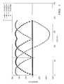
- FIG. 1is a graph of phase voltage versus motor position.
- FIG. 2is a graph of phase current versus duty cycle count without linearization.
- FIG. 3is a graph of FET gate voltage versus time depicting increasing duty cycles.
- FIG. 4is a schematic diagram of an exemplary EPS motor drive.
- FIG. 5is block diagram of an exemplary torque linearization device.
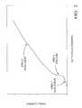
- FIG. 6is a graph of current versus duty cycle without linearization.
- FIG. 7graphically depicts an exemplary linearization table.
- FIG. 8depicts the relationship between duty cycle command count and current after linearization.
- the inventionmay be used in EPS systems using phase grounding pulse width modulation technique to control of a motor.
- a controllerwhich includes of a vehicle interface stage, a microprocessor, motor control logic and a power inverter stage.
- Control of the motoris achieved by providing a pulse width modulated signal having a duty cycle to a power inverter (also referred to as a gate drive) which utilizes a number of switching devices (e.g., field effect transistors or FET's) to provide current to the phase windings in the motor.
- a power inverteralso referred to as a gate drive
- An increase in duty cycleincreases the current delivered to the motor and thus increases the steering assistance provide by the motor.
- the phase grounding control methodgenerates non-linear torque near the on-center condition where the duty cycle is low.
- a point on the sinusoidal look up table(LUT) is chosen.
- the sinusoidal LUT'sare used to determine the voltage applied to each phase of the motor.
- FIG. 1displays the sine LUT's plotted as magnitude vs. motor position.
- a point on the LUTis selected where the phase An upper gate drive is the only upper gate that will be enhanced.
- the other two upper FET's for phases B and Cwill not be pulse width modulating at this point due to the voltage magnitude being zero. This point is shown at motor position 64 in FIG. 1 . Selecting this point isolates phase A for torque linearization analysis.
- FIG. 2With the motor position value locked at 64 counts, a typical plot of duty cycle command vs. phase current is depicted in FIG. 2 .
- FIG. 2there are basically two different non-linear portions of the curve along with a jump in current that is commonly referred to as preload.
- preloadThere is also a “dead band” area at the first few duty cycle counts that results because there is not enough voltage at the gate drive to enhance the FET.
- FIG. 3approximates gate drive voltages for the gate An upper FET during turn on for several incremental duty cycle commands.
- state 1is the “dead band state” because the FET gate drive voltage is not high enough to drive the FET into its linear region. This results in the phase current “dead band” in FIG. 2 at the first few duty cycles.
- State 2 in FIG. 3represents the FET gate drive voltage in the linear region when the FET is not fully enhanced. Incremental duty cycles ending in this region result in drain current that increase in a non-linear fashion. When duty cycles end in this region the non-linearity shown in Area 1 of FIG. 2 is evident. During the end of State 2 the FET becomes fully enhanced which causes a rise in current that is shown as the preload in Area 2 of FIG. 2 . Duty cycles that end after the FET has been fully enhanced now increase in a linear fashion.
- the torque rippleoccurs when a small amount of torque is applied to the hand wheel “on-center” or in the neighborhood of a center position of the hand wheel, but receives little or no assist from the motor because the FET's in the gate drive are operating in Area 1 of FIG. 2 .
- the FET's in the gate driveare operating in Area 1 of FIG. 2 .
- the driverincreases torque to the hand wheel the FET's become fully enhanced and the preload effect of Area 2 in FIG. 2 results in an overshoot (or amplification) of torque assist.
- This scenariocreates one or multiple torque ripple bumps when the hand wheel is at or near the on-center position.
- the non-linearity of Area 3also results in improper torque assistance but is not as prevalent and may be reduced through software calibration.
- One embodiment of the inventionsolves this on-center torque ripple problem by altering the duty cycle of the motor control signal based on the phase current needed to maintain a smooth feel to the driver.
- a tablecan be developed to linearize FIG. 2 . This table is dependent on factors in the power stage and the motor itself and may of course be altered as motor and power stage parameters change. Generation of the linearization table and its implementation are described herein.
- reference numeral 10generally designates an EPS system suitable for implementation of the invention.
- a brushless motor 12provides a position signal ⁇ via line 14 into a torque control device 16 .
- the torque control device 16 , a sine PWM generator 20 and voltage-torque linearization device 32may be implemented using a controller (e.g., a microprocessor) executing a stored computer program.
- the position signal ⁇along with a torque command signal Tcmd provide the inputs of the torque control device 16 .
- the outputs of the torque control device 16 , a V signal and a ⁇ signalare provided to a sine pulse width modulation (PWM) generator 20 .
- PWMsine pulse width modulation
- the outputs of the sine pulse width modulation (PWM) generator 20is a control signal having duty cycle Da, Db and Dc which correspond to the duty cycles for each phase of the motor.
- the initial duty cycles, Da, Db and Dcare inputted to a torque linearization device 32 .
- This torque linearization device 32is described in detail with reference to FIG. 5 .
- the torque linearization device 32generates adjusted duty cycles, Da′, Db′ and Dc′ which are applied to an inverter 40 .
- the inverter 40may include a set of power switches such as FET's.
- the outputs of the inverter 40are applied to the stator of the brushless motor 12 .
- FIG. 5is a block diagram of the torque linearization device 32 of FIG. 4 .
- the processing performed by the torque linearization device 32is described with reference to a singe phase and it is understood that similar processing may be performed for all phases of a multi-phase motor.
- the input duty cycle D inis compared to a threshold DL max at comparator 50 . As described above, linearization is needed primarily for low duty cycle counts and thus, if the initial duty cycle is greater than the threshold, linearization is not needed.
- the result of the comparatoris provided to a duty cycle selector 54 described herein.
- the initial duty cycle D inis provided to a linearization table 52 which linearizes the initial duty cycle values.
- the linearization table 52is described herein with reference to FIGS. 6-8.
- the initial duty cycle and the linearized duty cycleare provided to duty cycle selector 54 which selects the initial duty cycle if the initial duty cycle exceeds the threshold DL max and selects the linearized duty cycle otherwise.
- the output of the selector 54is referred to as the secondary duty cycle.
- the output of selector 54is provided to summer 56 where a duty cycle offset D offset is added to generate an adjusted duty cycle D out .
- FIG. 6is plot of phase current vs. duty cycle count for one phase of the motor 12 and shows the non-linearity particularly for low duty cycles.
- a line 80is fit to the linear portion of the plot.
- the offsetis 15 duty cycle counts.
- the offset D offsetis used so that the linearized curve passes through zero duty cycle counts.
- the vertical lineshows the point (approximately 40 counts) at which the original curve starts to become linear.
- the linearization tableshould be one-to-one meaning the linearized duty cycle count equals the initial duty cycle count.
- the threshold DL maxmay be set at a somewhat higher duty cycle count (e.g. 60 counts).
- Table 1displays the linearization table that will be used in the for linearization table 52 for the example shown in FIG. 6 .
- FIG. 7is a graphical depiction of the linearization table represented in Table 1.
- FIG. 8is a graph of current versus duty cycle count upon applying the linearization table 52 and adding the duty cycle offset D offset . As shown in FIG. 8, the current follows duty cycle count in a linear fashion.
- the present inventionprovides a method and apparatus for linearizing torque in an EPS system.
- the linearization tablethat will be used in the phase grounding method of sinusoidal control results in the reduction of on-center feel problems (torque ripple) in the electric power steering system.
- the present inventioncan be embodied in the form of computer-implemented processes and apparatuses for practicing those processes.
- the present inventioncan also be embodied in the form of computer program code containing instructions embodied in tangible media, such as floppy diskettes, CD-ROMs, hard drives, or any other computer-readable storage medium, wherein, when the computer program code is loaded into and executed by a computer, the computer becomes an apparatus for practicing the invention.
- the present inventioncan also be embodied in the form of computer program code, for example, whether stored in a storage medium, loaded into and/or executed by a computer, or transmitted over some transmission medium, such as over electrical wiring or cabling, through fiber optics, or via electromagnetic radiation, wherein, when the computer program code is loaded into and executed by a computer, the computer becomes an apparatus for practicing the invention.
- computer program code segmentsconfigure the microprocessor to create specific logic circuits.
Landscapes
- Engineering & Computer Science (AREA)
- Physics & Mathematics (AREA)
- General Physics & Mathematics (AREA)
- Automation & Control Theory (AREA)
- Chemical & Material Sciences (AREA)
- Combustion & Propulsion (AREA)
- Transportation (AREA)
- Mechanical Engineering (AREA)
- Control Of Motors That Do Not Use Commutators (AREA)
- Power Steering Mechanism (AREA)
- Steering Control In Accordance With Driving Conditions (AREA)
Abstract
Description
| TABLE 1 | |||
| Duty | |||
| Input | Output | ||
| 0 | 0 | ||
| 1 | 0 | ||
| 2 | 0 | ||
| 3 | 9 | ||
| 4 | 9 | ||
| 5 | 10 | ||
| 6 | 10 | ||
| 7 | 11 | ||
| 8 | 11 | ||
| 9 | 12 | ||
| 10 | 12 | ||
| 11 | 13 | ||
| 12 | 14 | ||
| 13 | 15 | ||
| 14 | 16 | ||
| 15 | 16 | ||
| 16 | 17 | ||
| 17 | 18 | ||
| 18 | 19 | ||
| 19 | 20 | ||
| 20 | 21 | ||
| 21 | 22 | ||
| 22 | 22 | ||
| 23 | 23 | ||
| 24 | 24 | ||
| 25 | 25 | ||
| 26 | 26 | ||
| 27 | 27 | ||
| 28 | 28 | ||
| 29 | 29 | ||
| 30 | 30 | ||
| 31 | 31 | ||
| 32 | 32 | ||
| 33 | 33 | ||
| 34 | 34 | ||
| 35 | 35 | ||
| 36 | 36 | ||
| 37 | 37 | ||
| 38 | 38 | ||
| 39 | 39 | ||
| 40 | 40 | ||
| 41 | 41 | ||
| 42 | 42 | ||
| 43 | 43 | ||
| 44 | 44 | ||
| 45 | 45 | ||
| 46 | 46 | ||
| 47 | 47 | ||
| 48 | 48 | ||
| 49 | 49 | ||
| 50 | 50 | ||
| 51 | 51 | ||
| 52 | 52 | ||
| 53 | 53 | ||
| 54 | 54 | ||
| 55 | 55 | ||
| 56 | 56 | ||
| 57 | 57 | ||
| 58 | 58 | ||
| 59 | 59 | ||
| 60 | 60 | ||
| 61 | 61 | ||
| 62 | 62 | ||
| 63 | 63 | ||
Claims (14)
Priority Applications (1)
| Application Number | Priority Date | Filing Date | Title |
|---|---|---|---|
| US09/652,237US6441578B1 (en) | 1999-09-16 | 2000-08-31 | Method and apparatus for torque linearization in an electric power steering system |
Applications Claiming Priority (2)
| Application Number | Priority Date | Filing Date | Title |
|---|---|---|---|
| US15405299P | 1999-09-16 | 1999-09-16 | |
| US09/652,237US6441578B1 (en) | 1999-09-16 | 2000-08-31 | Method and apparatus for torque linearization in an electric power steering system |
Publications (1)
| Publication Number | Publication Date |
|---|---|
| US6441578B1true US6441578B1 (en) | 2002-08-27 |
Family
ID=22549797
Family Applications (1)
| Application Number | Title | Priority Date | Filing Date |
|---|---|---|---|
| US09/652,237Expired - LifetimeUS6441578B1 (en) | 1999-09-16 | 2000-08-31 | Method and apparatus for torque linearization in an electric power steering system |
Country Status (5)
| Country | Link |
|---|---|
| US (1) | US6441578B1 (en) |
| EP (1) | EP1216437B1 (en) |
| JP (1) | JP2003509277A (en) |
| DE (1) | DE60043893D1 (en) |
| WO (1) | WO2001020411A1 (en) |
Cited By (8)
| Publication number | Priority date | Publication date | Assignee | Title |
|---|---|---|---|---|
| US20030071595A1 (en)* | 2001-10-11 | 2003-04-17 | Hyun-Min Cho | Motor control drive circuit |
| US6639375B2 (en)* | 2001-10-30 | 2003-10-28 | Harold Beck And Sons, Inc. | Control device and method for controlling a control element |
| US20040000889A1 (en)* | 2002-06-26 | 2004-01-01 | Collier-Hallman Steven James | Method of inverter linearization in electric machines through secondary modulation |
| US6690135B2 (en)* | 2002-01-24 | 2004-02-10 | Delphi Technologies, Inc. | Method for compensating for dead time non-linearities in a pulse width modulation controlled switching scheme |
| CN100350735C (en)* | 2004-09-21 | 2007-11-21 | 摩托罗拉公司 | Torque ripple reduction for a voltage mode motor controller |
| US20080299182A1 (en)* | 2007-03-01 | 2008-12-04 | Shuyuan Zhang | Methods and formulations for topical gene therapy |
| US20090128072A1 (en)* | 2007-11-16 | 2009-05-21 | Honeywell International, Inc. | Dual lane control of a permanent magnet brushless motor using non-trapezoidal commutation control |
| CN109000846A (en)* | 2018-05-25 | 2018-12-14 | 万向钱潮传动轴有限公司 | A kind of EPS torque angle sensor detection device |
Families Citing this family (3)
| Publication number | Priority date | Publication date | Assignee | Title |
|---|---|---|---|---|
| DE10160477A1 (en)* | 2001-12-08 | 2003-06-18 | Ballard Power Systems | Method for control of an actuator for adjustment of a hydraulic valve by use of a pulse width modulated signal, involves controlling operating time intervals to optimize valve switching |
| KR101280141B1 (en) | 2009-03-06 | 2013-06-28 | 주식회사 만도 | Method for Controlling Fail-Safe and Electric Power Steering Apparatus Therefor |
| CN107117205B (en)* | 2017-05-11 | 2018-12-14 | 安徽江淮汽车集团股份有限公司 | A kind of electric boosting steering system with fault diagnosis |
Citations (49)
| Publication number | Priority date | Publication date | Assignee | Title |
|---|---|---|---|---|
| US3919609A (en) | 1972-07-14 | 1975-11-11 | Siemens Ag | Method and circuit for reducing the torque ripple of a rotating-field machine |
| US4027213A (en) | 1974-03-28 | 1977-05-31 | Valroger Pierre Albert Marie D | Electronic switching arrangement for energizing electric motors |
| US4217508A (en) | 1977-04-08 | 1980-08-12 | Sony Corporation | DC motor |
| US4240020A (en) | 1977-07-04 | 1980-12-16 | Hitachi, Ltd. | Control system for suppressing torque ripple in synchronous motor |
| US4300081A (en) | 1980-03-14 | 1981-11-10 | General Motors Corporation | Motor voltage feedback for a servo motor control system |
| US4392094A (en) | 1979-09-19 | 1983-07-05 | Siemens Aktiengesellschaft | Brushless D-C motor |
| US4447771A (en) | 1981-08-31 | 1984-05-08 | Kollmorgen Technologies Corporation | Control system for synchronous brushless motors |
| US4458192A (en) | 1982-03-12 | 1984-07-03 | Fanuc Ltd. | A.C. Motor drive apparatus |
| US4511827A (en) | 1981-08-03 | 1985-04-16 | Hitachi, Ltd. | Apparatus for driving a polyphase brushless motor with a suppressed torque ripple |
| US4556811A (en) | 1980-01-10 | 1985-12-03 | Electric Indicator Company, Inc. | Coil unit and coil form for electrical machines |
| US4628499A (en) | 1984-06-01 | 1986-12-09 | Scientific-Atlanta, Inc. | Linear servoactuator with integrated transformer position sensor |
| US4661756A (en)* | 1984-10-19 | 1987-04-28 | Kollmorgen Technologies Corporation | Servomotor control systems |
| US4691269A (en) | 1983-11-28 | 1987-09-01 | Matsushita Electric Industrial Co., Ltd. | PWM inverter apparatus |
| US4825132A (en) | 1987-05-21 | 1989-04-25 | Eaton Corporation | Current mode motor control |
| US4868477A (en) | 1987-06-23 | 1989-09-19 | The Superior Electric Company | Method and apparatus for controlling torque and torque ripple in a variable reluctance motor |
| US4868970A (en) | 1985-03-08 | 1989-09-26 | Kolimorgen Corporation | Method of making an electric motor |
| US4882524A (en) | 1987-04-22 | 1989-11-21 | I Soo Lee | Multi-phase bipolar brushless D.C. motor |
| US5063011A (en) | 1989-06-12 | 1991-11-05 | Hoeganaes Corporation | Doubly-coated iron particles |
| US5069972A (en) | 1988-09-12 | 1991-12-03 | Versic Ronald J | Moldable microcapsule that contains a high percentage of solid core material, and method of manufacture thereof |
| US5122719A (en) | 1991-02-27 | 1992-06-16 | Eastman Kodak Company | Method and apparatus for reducing recurrent fluctuations in motor torque |
| US5155419A (en) | 1989-10-19 | 1992-10-13 | Sankyo Seiki Mfg. Co., Ltd. | Brushless motor drive circuit having a highly accurate sinusoidal output signal |
| US5223775A (en) | 1991-10-28 | 1993-06-29 | Eml Research, Inc. | Apparatus and related method to compensate for torque ripple in a permanent magnet electric motor |
| US5257828A (en) | 1992-06-03 | 1993-11-02 | Trw Inc. | Method and apparatus for controlling damping in an electric assist steering system for vehicle yaw rate control |
| US5319294A (en) | 1992-05-28 | 1994-06-07 | Matsushita Electric Industrial Co., Ltd. | Apparatus for automatically adjusting offset correction values for current detectors |
| US5444341A (en) | 1993-11-04 | 1995-08-22 | Cincinnati Milacron Inc. | Method and apparatus for torque ripple compensation |
| US5451900A (en) | 1993-03-17 | 1995-09-19 | Kabushiki Kaisha Toshiba | Pulse width modulation circuit |
| US5469215A (en) | 1993-08-02 | 1995-11-21 | Okuma Corporation | Method and apparatus for controlling an electric motor with compensation or torque ripple |
| US5579188A (en) | 1995-06-06 | 1996-11-26 | Seagate Technology, Inc. | Ironless spindle motor for disc drive |
| US5616999A (en) | 1994-02-10 | 1997-04-01 | Nippondenso Co., Ltd. | Torque detecting apparatus for reducing torque ripple in an AC motor |
| US5625542A (en) | 1994-06-03 | 1997-04-29 | Inventio Ag | Low-noise operation of a machine fed by a pulse inverter |
| US5645496A (en) | 1993-12-28 | 1997-07-08 | Sumitomo Rubber Industries, Ltd. | Two-piece golf ball |
| US5672944A (en) | 1994-09-07 | 1997-09-30 | Itt Automotive Electrical Systems Inc. | Method and apparatus for minimizing torque ripple in a DC brushless motor using phase current overlap |
| US5760562A (en) | 1994-11-08 | 1998-06-02 | Dana Corporation | Apparatus and method for generating digital position signals for a rotatable shaft |
| US5777449A (en) | 1996-12-31 | 1998-07-07 | Sgs-Thomson Microelectronics, Inc. | Torque ripple reduction using back-emf feedback |
| US5780986A (en)* | 1995-03-02 | 1998-07-14 | Hewlett-Packard Company | Soft switching, PWM controller and method for reducing torque ripple in multiphase DC motor |
| US5852355A (en) | 1996-05-23 | 1998-12-22 | Switched Reluctance Drives Limited | Output smoothing in a switched reluctance machine |
| US5867380A (en) | 1996-03-26 | 1999-02-02 | Lg Industrial Systems Co., Ltd. | Method and apparatus for compensating voltage error caused by dead time of motor driving inverter |
| US5898990A (en) | 1997-04-14 | 1999-05-04 | General Motors Corporation | Method of assembling a magnet ring on a rotor |
| US5920161A (en) | 1997-05-26 | 1999-07-06 | Hitachi, Ltd. | Driving system for permanent magnet type synchronous machine suitable for electric vehicle and driving control method using the same |
| US5963706A (en) | 1997-10-23 | 1999-10-05 | Baik; Edward Hyeen | Control system for multi-phase brushless DC motor |
| US5977740A (en) | 1997-05-14 | 1999-11-02 | Itt Manufacturing Enterprises, Inc. | Brake-by-wire system with switched reluctance motor controller |
| US5998945A (en) | 1996-12-12 | 1999-12-07 | Switched Reluctance Drives Limited | Hysteresis current controller for a reluctance machine |
| US6002226A (en)* | 1998-06-17 | 1999-12-14 | General Motors Corporation | Brushless DC motor control method and apparatus for reduced commutation noise |
| US6008599A (en) | 1994-11-04 | 1999-12-28 | Trw Inc. | Method and apparatus for controlling an electric assist motor |
| US6046560A (en) | 1998-03-20 | 2000-04-04 | Trw Inc. | Electric assist steering system having an improved motor current controller with gain scheduler |
| US6049473A (en) | 1999-02-11 | 2000-04-11 | Delta Electronics, Inc. | Harmonic-injection control technique for three-phase, discontinuous-conduction-mode, high-power-factor boost rectifiers with improved line-transient response |
| US6051942A (en)* | 1996-04-12 | 2000-04-18 | Emerson Electric Motor Co. | Method and apparatus for controlling a switched reluctance machine |
| US6107767A (en) | 1998-03-20 | 2000-08-22 | Trw Inc. | Electric assist steering system having an improved motor current controller with notch filter |
| US6124688A (en)* | 1996-01-11 | 2000-09-26 | Lucas Industries Public Limited Company | Motor drive control |
- 2000
- 2000-08-31USUS09/652,237patent/US6441578B1/ennot_activeExpired - Lifetime
- 2000-08-31EPEP00959691Apatent/EP1216437B1/ennot_activeExpired - Lifetime
- 2000-08-31JPJP2001523930Apatent/JP2003509277A/ennot_activeWithdrawn
- 2000-08-31DEDE60043893Tpatent/DE60043893D1/ennot_activeExpired - Lifetime
- 2000-08-31WOPCT/US2000/023959patent/WO2001020411A1/enactiveApplication Filing
Patent Citations (49)
| Publication number | Priority date | Publication date | Assignee | Title |
|---|---|---|---|---|
| US3919609A (en) | 1972-07-14 | 1975-11-11 | Siemens Ag | Method and circuit for reducing the torque ripple of a rotating-field machine |
| US4027213A (en) | 1974-03-28 | 1977-05-31 | Valroger Pierre Albert Marie D | Electronic switching arrangement for energizing electric motors |
| US4217508A (en) | 1977-04-08 | 1980-08-12 | Sony Corporation | DC motor |
| US4240020A (en) | 1977-07-04 | 1980-12-16 | Hitachi, Ltd. | Control system for suppressing torque ripple in synchronous motor |
| US4392094A (en) | 1979-09-19 | 1983-07-05 | Siemens Aktiengesellschaft | Brushless D-C motor |
| US4556811A (en) | 1980-01-10 | 1985-12-03 | Electric Indicator Company, Inc. | Coil unit and coil form for electrical machines |
| US4300081A (en) | 1980-03-14 | 1981-11-10 | General Motors Corporation | Motor voltage feedback for a servo motor control system |
| US4511827A (en) | 1981-08-03 | 1985-04-16 | Hitachi, Ltd. | Apparatus for driving a polyphase brushless motor with a suppressed torque ripple |
| US4447771A (en) | 1981-08-31 | 1984-05-08 | Kollmorgen Technologies Corporation | Control system for synchronous brushless motors |
| US4458192A (en) | 1982-03-12 | 1984-07-03 | Fanuc Ltd. | A.C. Motor drive apparatus |
| US4691269A (en) | 1983-11-28 | 1987-09-01 | Matsushita Electric Industrial Co., Ltd. | PWM inverter apparatus |
| US4628499A (en) | 1984-06-01 | 1986-12-09 | Scientific-Atlanta, Inc. | Linear servoactuator with integrated transformer position sensor |
| US4661756A (en)* | 1984-10-19 | 1987-04-28 | Kollmorgen Technologies Corporation | Servomotor control systems |
| US4868970A (en) | 1985-03-08 | 1989-09-26 | Kolimorgen Corporation | Method of making an electric motor |
| US4882524A (en) | 1987-04-22 | 1989-11-21 | I Soo Lee | Multi-phase bipolar brushless D.C. motor |
| US4825132A (en) | 1987-05-21 | 1989-04-25 | Eaton Corporation | Current mode motor control |
| US4868477A (en) | 1987-06-23 | 1989-09-19 | The Superior Electric Company | Method and apparatus for controlling torque and torque ripple in a variable reluctance motor |
| US5069972A (en) | 1988-09-12 | 1991-12-03 | Versic Ronald J | Moldable microcapsule that contains a high percentage of solid core material, and method of manufacture thereof |
| US5063011A (en) | 1989-06-12 | 1991-11-05 | Hoeganaes Corporation | Doubly-coated iron particles |
| US5155419A (en) | 1989-10-19 | 1992-10-13 | Sankyo Seiki Mfg. Co., Ltd. | Brushless motor drive circuit having a highly accurate sinusoidal output signal |
| US5122719A (en) | 1991-02-27 | 1992-06-16 | Eastman Kodak Company | Method and apparatus for reducing recurrent fluctuations in motor torque |
| US5223775A (en) | 1991-10-28 | 1993-06-29 | Eml Research, Inc. | Apparatus and related method to compensate for torque ripple in a permanent magnet electric motor |
| US5319294A (en) | 1992-05-28 | 1994-06-07 | Matsushita Electric Industrial Co., Ltd. | Apparatus for automatically adjusting offset correction values for current detectors |
| US5257828A (en) | 1992-06-03 | 1993-11-02 | Trw Inc. | Method and apparatus for controlling damping in an electric assist steering system for vehicle yaw rate control |
| US5451900A (en) | 1993-03-17 | 1995-09-19 | Kabushiki Kaisha Toshiba | Pulse width modulation circuit |
| US5469215A (en) | 1993-08-02 | 1995-11-21 | Okuma Corporation | Method and apparatus for controlling an electric motor with compensation or torque ripple |
| US5444341A (en) | 1993-11-04 | 1995-08-22 | Cincinnati Milacron Inc. | Method and apparatus for torque ripple compensation |
| US5645496A (en) | 1993-12-28 | 1997-07-08 | Sumitomo Rubber Industries, Ltd. | Two-piece golf ball |
| US5616999A (en) | 1994-02-10 | 1997-04-01 | Nippondenso Co., Ltd. | Torque detecting apparatus for reducing torque ripple in an AC motor |
| US5625542A (en) | 1994-06-03 | 1997-04-29 | Inventio Ag | Low-noise operation of a machine fed by a pulse inverter |
| US5672944A (en) | 1994-09-07 | 1997-09-30 | Itt Automotive Electrical Systems Inc. | Method and apparatus for minimizing torque ripple in a DC brushless motor using phase current overlap |
| US6008599A (en) | 1994-11-04 | 1999-12-28 | Trw Inc. | Method and apparatus for controlling an electric assist motor |
| US5760562A (en) | 1994-11-08 | 1998-06-02 | Dana Corporation | Apparatus and method for generating digital position signals for a rotatable shaft |
| US5780986A (en)* | 1995-03-02 | 1998-07-14 | Hewlett-Packard Company | Soft switching, PWM controller and method for reducing torque ripple in multiphase DC motor |
| US5579188A (en) | 1995-06-06 | 1996-11-26 | Seagate Technology, Inc. | Ironless spindle motor for disc drive |
| US6124688A (en)* | 1996-01-11 | 2000-09-26 | Lucas Industries Public Limited Company | Motor drive control |
| US5867380A (en) | 1996-03-26 | 1999-02-02 | Lg Industrial Systems Co., Ltd. | Method and apparatus for compensating voltage error caused by dead time of motor driving inverter |
| US6051942A (en)* | 1996-04-12 | 2000-04-18 | Emerson Electric Motor Co. | Method and apparatus for controlling a switched reluctance machine |
| US5852355A (en) | 1996-05-23 | 1998-12-22 | Switched Reluctance Drives Limited | Output smoothing in a switched reluctance machine |
| US5998945A (en) | 1996-12-12 | 1999-12-07 | Switched Reluctance Drives Limited | Hysteresis current controller for a reluctance machine |
| US5777449A (en) | 1996-12-31 | 1998-07-07 | Sgs-Thomson Microelectronics, Inc. | Torque ripple reduction using back-emf feedback |
| US5898990A (en) | 1997-04-14 | 1999-05-04 | General Motors Corporation | Method of assembling a magnet ring on a rotor |
| US5977740A (en) | 1997-05-14 | 1999-11-02 | Itt Manufacturing Enterprises, Inc. | Brake-by-wire system with switched reluctance motor controller |
| US5920161A (en) | 1997-05-26 | 1999-07-06 | Hitachi, Ltd. | Driving system for permanent magnet type synchronous machine suitable for electric vehicle and driving control method using the same |
| US5963706A (en) | 1997-10-23 | 1999-10-05 | Baik; Edward Hyeen | Control system for multi-phase brushless DC motor |
| US6046560A (en) | 1998-03-20 | 2000-04-04 | Trw Inc. | Electric assist steering system having an improved motor current controller with gain scheduler |
| US6107767A (en) | 1998-03-20 | 2000-08-22 | Trw Inc. | Electric assist steering system having an improved motor current controller with notch filter |
| US6002226A (en)* | 1998-06-17 | 1999-12-14 | General Motors Corporation | Brushless DC motor control method and apparatus for reduced commutation noise |
| US6049473A (en) | 1999-02-11 | 2000-04-11 | Delta Electronics, Inc. | Harmonic-injection control technique for three-phase, discontinuous-conduction-mode, high-power-factor boost rectifiers with improved line-transient response |
Cited By (12)
| Publication number | Priority date | Publication date | Assignee | Title |
|---|---|---|---|---|
| US20030071595A1 (en)* | 2001-10-11 | 2003-04-17 | Hyun-Min Cho | Motor control drive circuit |
| US6861815B2 (en)* | 2001-10-11 | 2005-03-01 | Fairchild Korea Semiconductor Ltd. | Motor control drive circuit |
| US6639375B2 (en)* | 2001-10-30 | 2003-10-28 | Harold Beck And Sons, Inc. | Control device and method for controlling a control element |
| US6690135B2 (en)* | 2002-01-24 | 2004-02-10 | Delphi Technologies, Inc. | Method for compensating for dead time non-linearities in a pulse width modulation controlled switching scheme |
| US20040000889A1 (en)* | 2002-06-26 | 2004-01-01 | Collier-Hallman Steven James | Method of inverter linearization in electric machines through secondary modulation |
| US7190135B2 (en) | 2002-06-26 | 2007-03-13 | Delphi Technologies, Inc. | Method of inverter linearization in electric machines through secondary modulation |
| CN100350735C (en)* | 2004-09-21 | 2007-11-21 | 摩托罗拉公司 | Torque ripple reduction for a voltage mode motor controller |
| US20080299182A1 (en)* | 2007-03-01 | 2008-12-04 | Shuyuan Zhang | Methods and formulations for topical gene therapy |
| US20090128072A1 (en)* | 2007-11-16 | 2009-05-21 | Honeywell International, Inc. | Dual lane control of a permanent magnet brushless motor using non-trapezoidal commutation control |
| US8084972B2 (en)* | 2007-11-16 | 2011-12-27 | Honeywell International Inc. | Dual lane control of a permanent magnet brushless motor using non-trapezoidal commutation control |
| CN109000846A (en)* | 2018-05-25 | 2018-12-14 | 万向钱潮传动轴有限公司 | A kind of EPS torque angle sensor detection device |
| CN109000846B (en)* | 2018-05-25 | 2024-05-24 | 万向钱潮传动轴有限公司 | EPS moment of torsion corner sensor detection device |
Also Published As
| Publication number | Publication date |
|---|---|
| JP2003509277A (en) | 2003-03-11 |
| DE60043893D1 (en) | 2010-04-08 |
| EP1216437A4 (en) | 2009-04-08 |
| WO2001020411A1 (en) | 2001-03-22 |
| EP1216437A1 (en) | 2002-06-26 |
| WO2001020411A9 (en) | 2002-09-12 |
| EP1216437B1 (en) | 2010-02-24 |
Similar Documents
| Publication | Publication Date | Title |
|---|---|---|
| US10494017B2 (en) | Electric power steering apparatus | |
| US11097772B2 (en) | Motor control unit and electric power steering apparatus equipped with the same | |
| US9553540B2 (en) | Power converter with pre-compensation for dead-time insertion | |
| US6441578B1 (en) | Method and apparatus for torque linearization in an electric power steering system | |
| CN102047552B (en) | Motor control device and electric power steering device | |
| US7106017B2 (en) | Motor control device | |
| US20040007999A1 (en) | Active deadtime control for improved torque ripple performance in electric machines | |
| CN101083448A (en) | Method and apparatus for PWM control of voltage source inverter | |
| KR20110021710A (en) | Pulse width modulation dead time compensation method and apparatus | |
| EP3614558B1 (en) | Motor control device and electric power steering device equipped with same | |
| US9960726B1 (en) | Electric drive power converter with low distortion dead-time insertion | |
| WO2018155321A1 (en) | Control device and electric power steering device using same | |
| US11637502B2 (en) | Startup process for a dual active bridge converter to prevent over-voltage failure and thermal run-away | |
| JP7609705B2 (en) | Power Conversion Equipment | |
| US20200395882A1 (en) | Electric power steering apparatus | |
| WO2022018841A1 (en) | Power conversion device and electric power steering device | |
| US12176826B2 (en) | Inverter driving apparatus and control method thereof | |
| EP4120559B1 (en) | Pwm driving method for an electric motor with zero-crossing compensation | |
| JP5515787B2 (en) | Rotating electrical machine control system | |
| CN102177655B (en) | Method and device for reducing electromagnetic emissions during switch-on of power semiconductors | |
| US7049777B2 (en) | Motor control device and motor control method | |
| CN112385137A (en) | Control device for electric power steering device | |
| JP2018148642A (en) | Motor drive circuit | |
| JP2023009867A (en) | Control device | |
| JP3804707B2 (en) | Motor control device and motor control switching method |
Legal Events
| Date | Code | Title | Description |
|---|---|---|---|
| AS | Assignment | Owner name:DELPHI TECHNOLOGIES, INC., MICHIGAN Free format text:ASSIGNMENT OF ASSIGNORS INTEREST;ASSIGNORS:MIR, SAYEED A.;SKELLENGER, DENNIS B.;REEL/FRAME:011222/0684 Effective date:20000920 | |
| STCF | Information on status: patent grant | Free format text:PATENTED CASE | |
| FPAY | Fee payment | Year of fee payment:4 | |
| AS | Assignment | Owner name:GM GLOBAL TECHNOLOGY OPERATIONS, INC., MICHIGAN Free format text:ASSIGNMENT OF ASSIGNORS INTEREST;ASSIGNOR:DELPHI TECHNOLOGIES, INC.;REEL/FRAME:023449/0065 Effective date:20091002 Owner name:GM GLOBAL TECHNOLOGY OPERATIONS, INC.,MICHIGAN Free format text:ASSIGNMENT OF ASSIGNORS INTEREST;ASSIGNOR:DELPHI TECHNOLOGIES, INC.;REEL/FRAME:023449/0065 Effective date:20091002 | |
| FPAY | Fee payment | Year of fee payment:8 | |
| AS | Assignment | Owner name:GM GLOBAL TECHNOLOGY OPERATIONS, INC.,MICHIGAN Free format text:ASSIGNMENT OF ASSIGNORS INTEREST;ASSIGNOR:DELPHI TECHNOLOGIES, INC.;REEL/FRAME:023988/0754 Effective date:20091002 Owner name:UNITED STATES DEPARTMENT OF THE TREASURY,DISTRICT Free format text:SECURITY AGREEMENT;ASSIGNOR:GM GLOBAL TECHNOLOGY OPERATIONS, INC.;REEL/FRAME:023990/0349 Effective date:20090710 Owner name:UAW RETIREE MEDICAL BENEFITS TRUST,MICHIGAN Free format text:SECURITY AGREEMENT;ASSIGNOR:GM GLOBAL TECHNOLOGY OPERATIONS, INC.;REEL/FRAME:023990/0831 Effective date:20090710 Owner name:GM GLOBAL TECHNOLOGY OPERATIONS, INC., MICHIGAN Free format text:ASSIGNMENT OF ASSIGNORS INTEREST;ASSIGNOR:DELPHI TECHNOLOGIES, INC.;REEL/FRAME:023988/0754 Effective date:20091002 Owner name:UNITED STATES DEPARTMENT OF THE TREASURY, DISTRICT Free format text:SECURITY AGREEMENT;ASSIGNOR:GM GLOBAL TECHNOLOGY OPERATIONS, INC.;REEL/FRAME:023990/0349 Effective date:20090710 Owner name:UAW RETIREE MEDICAL BENEFITS TRUST, MICHIGAN Free format text:SECURITY AGREEMENT;ASSIGNOR:GM GLOBAL TECHNOLOGY OPERATIONS, INC.;REEL/FRAME:023990/0831 Effective date:20090710 | |
| AS | Assignment | Owner name:GM GLOBAL TECHNOLOGY OPERATIONS, INC., MICHIGAN Free format text:ASSIGNMENT OF ASSIGNORS INTEREST;ASSIGNOR:DELPHI TECHNOLOGIES, INC.;REEL/FRAME:025204/0846 Effective date:20101014 | |
| AS | Assignment | Owner name:GM GLOBAL TECHNOLOGY OPERATIONS, INC., MICHIGAN Free format text:RELEASE BY SECURED PARTY;ASSIGNOR:UAW RETIREE MEDICAL BENEFITS TRUST;REEL/FRAME:025386/0503 Effective date:20101026 Owner name:GM GLOBAL TECHNOLOGY OPERATIONS, INC., MICHIGAN Free format text:RELEASE BY SECURED PARTY;ASSIGNOR:UNITED STATES DEPARTMENT OF THE TREASURY;REEL/FRAME:025386/0591 Effective date:20100420 | |
| AS | Assignment | Owner name:GM GLOBAL TECHNOLOGY OPERATIONS, INC., MICHIGAN Free format text:ASSIGNMENT OF ASSIGNORS INTEREST;ASSIGNOR:GM GLOBAL TECHNOLOGY OPERATIONS, INC.;REEL/FRAME:027842/0918 Effective date:20101130 Owner name:PACIFIC CENTURY MOTORS, INC., CHINA Free format text:ASSIGNMENT OF ASSIGNORS INTEREST;ASSIGNOR:GM GLOBAL TECHNOLOGY OPERATIONS, INC.;REEL/FRAME:027842/0918 Effective date:20101130 | |
| AS | Assignment | Owner name:STEERING SOLUTIONS IP HOLDING CORPORATION, MICHIGA Free format text:ASSIGNMENT OF ASSIGNORS INTEREST;ASSIGNORS:PACIFIC CENTURY MOTORS, INC.;NEXTEER (BEIJING) TECHNOLOGY CO., LTD.;REEL/FRAME:027870/0666 Effective date:20120126 | |
| FPAY | Fee payment | Year of fee payment:12 |