US6441503B1 - Bond wire pressure sensor die package - Google Patents
Bond wire pressure sensor die packageDownload PDFInfo
- Publication number
- US6441503B1 US6441503B1US09/754,393US75439301AUS6441503B1US 6441503 B1US6441503 B1US 6441503B1US 75439301 AUS75439301 AUS 75439301AUS 6441503 B1US6441503 B1US 6441503B1
- Authority
- US
- United States
- Prior art keywords
- pressure sensor
- substrate
- die
- sensor die
- encapsulant
- Prior art date
- Legal status (The legal status is an assumption and is not a legal conclusion. Google has not performed a legal analysis and makes no representation as to the accuracy of the status listed.)
- Expired - Lifetime
Links
Images


Classifications
- G—PHYSICS
- G01—MEASURING; TESTING
- G01L—MEASURING FORCE, STRESS, TORQUE, WORK, MECHANICAL POWER, MECHANICAL EFFICIENCY, OR FLUID PRESSURE
- G01L19/00—Details of, or accessories for, apparatus for measuring steady or quasi-steady pressure of a fluent medium insofar as such details or accessories are not special to particular types of pressure gauges
- G01L19/14—Housings
- G01L19/141—Monolithic housings, e.g. molded or one-piece housings
- G—PHYSICS
- G01—MEASURING; TESTING
- G01L—MEASURING FORCE, STRESS, TORQUE, WORK, MECHANICAL POWER, MECHANICAL EFFICIENCY, OR FLUID PRESSURE
- G01L19/00—Details of, or accessories for, apparatus for measuring steady or quasi-steady pressure of a fluent medium insofar as such details or accessories are not special to particular types of pressure gauges
- G01L19/06—Means for preventing overload or deleterious influence of the measured medium on the measuring device or vice versa
- G01L19/0627—Protection against aggressive medium in general
- G01L19/0645—Protection against aggressive medium in general using isolation membranes, specially adapted for protection
- G—PHYSICS
- G01—MEASURING; TESTING
- G01L—MEASURING FORCE, STRESS, TORQUE, WORK, MECHANICAL POWER, MECHANICAL EFFICIENCY, OR FLUID PRESSURE
- G01L19/00—Details of, or accessories for, apparatus for measuring steady or quasi-steady pressure of a fluent medium insofar as such details or accessories are not special to particular types of pressure gauges
- G01L19/14—Housings
- G01L19/147—Details about the mounting of the sensor to support or covering means
- H—ELECTRICITY
- H01—ELECTRIC ELEMENTS
- H01L—SEMICONDUCTOR DEVICES NOT COVERED BY CLASS H10
- H01L21/00—Processes or apparatus adapted for the manufacture or treatment of semiconductor or solid state devices or of parts thereof
- H01L21/02—Manufacture or treatment of semiconductor devices or of parts thereof
- H01L21/04—Manufacture or treatment of semiconductor devices or of parts thereof the devices having potential barriers, e.g. a PN junction, depletion layer or carrier concentration layer
- H01L21/50—Assembly of semiconductor devices using processes or apparatus not provided for in a single one of the groups H01L21/18 - H01L21/326 or H10D48/04 - H10D48/07 e.g. sealing of a cap to a base of a container
- H01L21/56—Encapsulations, e.g. encapsulation layers, coatings
- H01L21/565—Moulds
- H—ELECTRICITY
- H01—ELECTRIC ELEMENTS
- H01L—SEMICONDUCTOR DEVICES NOT COVERED BY CLASS H10
- H01L23/00—Details of semiconductor or other solid state devices
- H01L23/28—Encapsulations, e.g. encapsulating layers, coatings, e.g. for protection
- H01L23/31—Encapsulations, e.g. encapsulating layers, coatings, e.g. for protection characterised by the arrangement or shape
- H01L23/3107—Encapsulations, e.g. encapsulating layers, coatings, e.g. for protection characterised by the arrangement or shape the device being completely enclosed
- H01L23/3121—Encapsulations, e.g. encapsulating layers, coatings, e.g. for protection characterised by the arrangement or shape the device being completely enclosed a substrate forming part of the encapsulation
- H01L23/3128—Encapsulations, e.g. encapsulating layers, coatings, e.g. for protection characterised by the arrangement or shape the device being completely enclosed a substrate forming part of the encapsulation the substrate having spherical bumps for external connection
- H—ELECTRICITY
- H01—ELECTRIC ELEMENTS
- H01L—SEMICONDUCTOR DEVICES NOT COVERED BY CLASS H10
- H01L2224/00—Indexing scheme for arrangements for connecting or disconnecting semiconductor or solid-state bodies and methods related thereto as covered by H01L24/00
- H01L2224/01—Means for bonding being attached to, or being formed on, the surface to be connected, e.g. chip-to-package, die-attach, "first-level" interconnects; Manufacturing methods related thereto
- H01L2224/02—Bonding areas; Manufacturing methods related thereto
- H01L2224/04—Structure, shape, material or disposition of the bonding areas prior to the connecting process
- H01L2224/05—Structure, shape, material or disposition of the bonding areas prior to the connecting process of an individual bonding area
- H01L2224/0554—External layer
- H01L2224/05599—Material
- H—ELECTRICITY
- H01—ELECTRIC ELEMENTS
- H01L—SEMICONDUCTOR DEVICES NOT COVERED BY CLASS H10
- H01L2224/00—Indexing scheme for arrangements for connecting or disconnecting semiconductor or solid-state bodies and methods related thereto as covered by H01L24/00
- H01L2224/01—Means for bonding being attached to, or being formed on, the surface to be connected, e.g. chip-to-package, die-attach, "first-level" interconnects; Manufacturing methods related thereto
- H01L2224/42—Wire connectors; Manufacturing methods related thereto
- H01L2224/44—Structure, shape, material or disposition of the wire connectors prior to the connecting process
- H01L2224/45—Structure, shape, material or disposition of the wire connectors prior to the connecting process of an individual wire connector
- H01L2224/45001—Core members of the connector
- H01L2224/45099—Material
- H—ELECTRICITY
- H01—ELECTRIC ELEMENTS
- H01L—SEMICONDUCTOR DEVICES NOT COVERED BY CLASS H10
- H01L2224/00—Indexing scheme for arrangements for connecting or disconnecting semiconductor or solid-state bodies and methods related thereto as covered by H01L24/00
- H01L2224/01—Means for bonding being attached to, or being formed on, the surface to be connected, e.g. chip-to-package, die-attach, "first-level" interconnects; Manufacturing methods related thereto
- H01L2224/42—Wire connectors; Manufacturing methods related thereto
- H01L2224/47—Structure, shape, material or disposition of the wire connectors after the connecting process
- H01L2224/48—Structure, shape, material or disposition of the wire connectors after the connecting process of an individual wire connector
- H01L2224/4805—Shape
- H01L2224/4809—Loop shape
- H01L2224/48091—Arched
- H—ELECTRICITY
- H01—ELECTRIC ELEMENTS
- H01L—SEMICONDUCTOR DEVICES NOT COVERED BY CLASS H10
- H01L2224/00—Indexing scheme for arrangements for connecting or disconnecting semiconductor or solid-state bodies and methods related thereto as covered by H01L24/00
- H01L2224/01—Means for bonding being attached to, or being formed on, the surface to be connected, e.g. chip-to-package, die-attach, "first-level" interconnects; Manufacturing methods related thereto
- H01L2224/42—Wire connectors; Manufacturing methods related thereto
- H01L2224/47—Structure, shape, material or disposition of the wire connectors after the connecting process
- H01L2224/48—Structure, shape, material or disposition of the wire connectors after the connecting process of an individual wire connector
- H01L2224/481—Disposition
- H01L2224/48151—Connecting between a semiconductor or solid-state body and an item not being a semiconductor or solid-state body, e.g. chip-to-substrate, chip-to-passive
- H01L2224/48221—Connecting between a semiconductor or solid-state body and an item not being a semiconductor or solid-state body, e.g. chip-to-substrate, chip-to-passive the body and the item being stacked
- H01L2224/48225—Connecting between a semiconductor or solid-state body and an item not being a semiconductor or solid-state body, e.g. chip-to-substrate, chip-to-passive the body and the item being stacked the item being non-metallic, e.g. insulating substrate with or without metallisation
- H01L2224/48227—Connecting between a semiconductor or solid-state body and an item not being a semiconductor or solid-state body, e.g. chip-to-substrate, chip-to-passive the body and the item being stacked the item being non-metallic, e.g. insulating substrate with or without metallisation connecting the wire to a bond pad of the item
- H—ELECTRICITY
- H01—ELECTRIC ELEMENTS
- H01L—SEMICONDUCTOR DEVICES NOT COVERED BY CLASS H10
- H01L2224/00—Indexing scheme for arrangements for connecting or disconnecting semiconductor or solid-state bodies and methods related thereto as covered by H01L24/00
- H01L2224/80—Methods for connecting semiconductor or other solid state bodies using means for bonding being attached to, or being formed on, the surface to be connected
- H01L2224/85—Methods for connecting semiconductor or other solid state bodies using means for bonding being attached to, or being formed on, the surface to be connected using a wire connector
- H01L2224/8538—Bonding interfaces outside the semiconductor or solid-state body
- H01L2224/85399—Material
- H—ELECTRICITY
- H01—ELECTRIC ELEMENTS
- H01L—SEMICONDUCTOR DEVICES NOT COVERED BY CLASS H10
- H01L2224/00—Indexing scheme for arrangements for connecting or disconnecting semiconductor or solid-state bodies and methods related thereto as covered by H01L24/00
- H01L2224/93—Batch processes
- H01L2224/95—Batch processes at chip-level, i.e. with connecting carried out on a plurality of singulated devices, i.e. on diced chips
- H01L2224/97—Batch processes at chip-level, i.e. with connecting carried out on a plurality of singulated devices, i.e. on diced chips the devices being connected to a common substrate, e.g. interposer, said common substrate being separable into individual assemblies after connecting
- H—ELECTRICITY
- H01—ELECTRIC ELEMENTS
- H01L—SEMICONDUCTOR DEVICES NOT COVERED BY CLASS H10
- H01L24/00—Arrangements for connecting or disconnecting semiconductor or solid-state bodies; Methods or apparatus related thereto
- H01L24/01—Means for bonding being attached to, or being formed on, the surface to be connected, e.g. chip-to-package, die-attach, "first-level" interconnects; Manufacturing methods related thereto
- H01L24/42—Wire connectors; Manufacturing methods related thereto
- H01L24/47—Structure, shape, material or disposition of the wire connectors after the connecting process
- H01L24/48—Structure, shape, material or disposition of the wire connectors after the connecting process of an individual wire connector
- H—ELECTRICITY
- H01—ELECTRIC ELEMENTS
- H01L—SEMICONDUCTOR DEVICES NOT COVERED BY CLASS H10
- H01L2924/00—Indexing scheme for arrangements or methods for connecting or disconnecting semiconductor or solid-state bodies as covered by H01L24/00
- H01L2924/0001—Technical content checked by a classifier
- H01L2924/00014—Technical content checked by a classifier the subject-matter covered by the group, the symbol of which is combined with the symbol of this group, being disclosed without further technical details
- H—ELECTRICITY
- H01—ELECTRIC ELEMENTS
- H01L—SEMICONDUCTOR DEVICES NOT COVERED BY CLASS H10
- H01L2924/00—Indexing scheme for arrangements or methods for connecting or disconnecting semiconductor or solid-state bodies as covered by H01L24/00
- H01L2924/10—Details of semiconductor or other solid state devices to be connected
- H01L2924/102—Material of the semiconductor or solid state bodies
- H01L2924/1025—Semiconducting materials
- H01L2924/10251—Elemental semiconductors, i.e. Group IV
- H01L2924/10253—Silicon [Si]
- H—ELECTRICITY
- H01—ELECTRIC ELEMENTS
- H01L—SEMICONDUCTOR DEVICES NOT COVERED BY CLASS H10
- H01L2924/00—Indexing scheme for arrangements or methods for connecting or disconnecting semiconductor or solid-state bodies as covered by H01L24/00
- H01L2924/15—Details of package parts other than the semiconductor or other solid state devices to be connected
- H01L2924/151—Die mounting substrate
- H01L2924/1515—Shape
- H01L2924/15151—Shape the die mounting substrate comprising an aperture, e.g. for underfilling, outgassing, window type wire connections
- H—ELECTRICITY
- H01—ELECTRIC ELEMENTS
- H01L—SEMICONDUCTOR DEVICES NOT COVERED BY CLASS H10
- H01L2924/00—Indexing scheme for arrangements or methods for connecting or disconnecting semiconductor or solid-state bodies as covered by H01L24/00
- H01L2924/15—Details of package parts other than the semiconductor or other solid state devices to be connected
- H01L2924/181—Encapsulation
- H01L2924/1815—Shape
- H—ELECTRICITY
- H01—ELECTRIC ELEMENTS
- H01L—SEMICONDUCTOR DEVICES NOT COVERED BY CLASS H10
- H01L2924/00—Indexing scheme for arrangements or methods for connecting or disconnecting semiconductor or solid-state bodies as covered by H01L24/00
- H01L2924/30—Technical effects
- H01L2924/301—Electrical effects
- H01L2924/3025—Electromagnetic shielding
Definitions
- the present inventionrelates generally to the packaging of electronic components. More particularly, the present invention relates to methods for making bond wire pressure sensor die packages.
- FIG. 1Aillustrates a pressure sensor die 10 suitable for use with the present invention.
- pressure sensor die 10is a piezoresistive pressure sensor. Piezoresistive pressure sensors are discussed, and one method for making piezoresistive pressure sensors is disclosed, in U.S. Pat. No. 5,719,069, entitled “ONE-CHIP INTEGRATED SENSOR PROCESS”, issued Feb. 17, 1998 to Sparks, which is incorporated, in its entirety, by reference herein. Another type of pressure sensor is disclosed in U.S. Pat. No. 3,748,571, entitled “PRESSURE SENSITIVE TRANSDUCERS EMPLOYING CAPACITIVE AND RESISTIVE VARIATIONS”, issued Jul. 24, 1973 to Kurtz, which is also incorporated, in its entirety, by reference herein.
- Pressure sensors and pressure sensor die assembliesare well known to those of skill in the art and come in a large variety of sizes and configurations. Consequently, while one embodiment of a pressure sensor die 10 is discussed below, it will be recognized by those of skill in the art that numerous other types of pressure sensors will work equally well with the present invention.
- pressure sensor die 10includes a pressure sensitive micro-machine element 54 which is a pressure sensing membrane composed of a portion of the epitaxial silicon layer 16 .
- Pressure sensor die 10also includes a plurality of piezoresistors 14 formed in epitaxial silicon layer 16 . Piezoresistors 14 serve as sensing elements for micro-machine element 54 .
- Pressure sensor die 10is formed by bonding a substrate 18 to a glass or silicon wafer 20 .
- Substrate 18includes a cavity 22 such that when substrate 18 is bonded to wafer 20 , wafer 20 seals cavity 22 .
- Cavity 22is positioned directly below micro-machine element 54 .
- wafer 20hermetically seals cavity 22 so that pressure sensor die 10 is an absolute pressure sensor.
- FIG. 1Bshows another embodiment of a pressure sensor die 10 B, which includes a die hole 60 through wafer 20 to vent cavity 22 making pressure sensor die 10 B a differential pressure sensor.
- a pressure sensor die 10 Bwhich includes a die hole 60 through wafer 20 to vent cavity 22 making pressure sensor die 10 B a differential pressure sensor.
- absolute pressure sensorssuch as pressure sensor die 10
- differential pressure sensorssuch as pressure sensor die 10 B.
- Pressure sensor die 10 or 10 Bis typically used to monitor the pressure of an external fluid, i.e., a gas or liquid, by placing first or outer surface 56 of pressure sensor die 10 or pressure sensor die 10 B, including micro-machine element 54 , in contact with the external fluid.
- micro-machine element 54flexes in response to pressure on first or outer surface 56 . This flex is sensed by piezoresistors 14 and processed to determine the pressure exerted on first or outer surface 56 by the external fluid, i.e., the pressure of the liquid or gas.
- first or outer surface 56including micro-machine element 54 must be flexibly coupled to the surrounding environment and cannot be shielded from that environment by interposing layers of packaging material such as plastics or epoxies.
- FIG. 1Cis an enlarged cross-sectional view of a pressure sensor sub-assembly 100 including a pressure sensor die 110 mounted on a substrate 102 in die attach region 131 .
- pressure sensor die 110(FIG. 1C) includes a pressure sensitive micro-machine element 154 composed of a portion of the epitaxial silicon layer 116 .
- pressure sensor die 110is formed by bonding a substrate 118 to a glass or silicon wafer 120 .
- Substrate 118includes a cavity 122 such that when substrate 118 is bonded to wafer 120 , wafer 120 seals cavity 122 .
- Cavity 122is positioned directly below micro-machine element 154 .
- Pressure sensor die 110is attached to a first surface 111 (a die attach surface) of substrate 102 in die attach region 131 using any one of several well-known adhesives 104 .
- Substrate 102is typically a printed circuit board (PCB).
- electrically conductive contacts or pads 106 on first or outer surface 130 of pressure sensor die 110are connected with electrically conductive bond wires 103 to electrically conductive traces 112 and/or electrically conductive regions (not shown) formed on first surface 111 of substrate 102 .
- Electrically conductive vias 114are formed through substrate 102 , from traces 112 and/or regions on first surface 111 to a second surface (the mounting surface) 140 of substrate 102 which is opposite first surface 111 .
- Electrically conductive traces 113 formed on second surface 140 of substrate 102extend to electrically conductive contact or pads 115 formed on second surface 140 of substrate 102 .
- Electrically conductive contacts 115are used to connect substrate 102 and pressure sensor die 110 to a larger system, such as a mother board (not shown), using well known methods such as solder balls, pins, leadless carrier chip (LCC) contacts or other surface mounts.
- a plurality of pressure sensor die packagesare fabricated simultaneously, in an array, to minimize the cost associated with each individual pressure sensor die package.
- a plurality of pressure sensor diceare attached to an array of pressure sensor die sites located on a substrate.
- the pressure sensor diceare then electrically connected to the pressure sensor die sites using, in one embodiment, standard wire bond techniques.
- the resulting array of pressure sensor die sub-assembliesis then molded, in one embodiment of the invention, using a mold tool that closes on three sides of the substrate so that a cavity is formed that is open on the fourth side.
- a first portion of the molding toolhas a plurality of insert pins that close on the outer surface of each pressure sensor die.
- a portion of the outer surface of the micro-machine element of each pressure sensor dieis left exposed at the bottom of a cavity in the molding encapsulant.
- the exposed outer surface of the micro-machine elementis covered with a pressure coupling gel that is applied in the shallow cavity.
- the coupling gelprotects micro-machine elements from the environment, yet is compressible and is capable of coupling pressure from the external environment to the micro-machine elements.
- the resulting array of packaged pressure sensor diceare then sigulated using well known sawing or laser techniques or by snapping a specially formed snap array.
- a holeis formed in the array substrate and the pressure sensor substrate to accommodate a differential pressure sensor die.
- a custom substrateis formed with a plurality of holes formed, one each, at pressure sensor die mounting sites.
- a plurality of pressure sensor diceare then attached to pressure sensor die mounting sites located on the substrate.
- the pressure sensor diceare then electrically connected to the pressure sensor sites using, in this embodiment, standard flip-chip techniques.
- the resulting array of pressure sensor die sub-assembliesis then molded, using a mold tool that closes on the substrate and is filled with encapsulant.
- a portion of the outer surface of the micro-machine element of each pressure sensor dieis left exposed at the bottom of the holes in the substrate.
- the exposed outer surface of the micro-machine elementis covered with a,pressure coupling gel applied in the hole in the substrate.
- the resulting array of packaged pressure sensorsare then sigulated using well known sawing or laser techniques or by snapping a specially formed snap array.
- a cavityis formed in the encapsulant and the pressure sensor substrate to accommodate a differential pressure sensor die.
- one embodiment of the inventionincludes: a pressure sensor die, the pressure sensor die having a pressure sensor die first surface and a pressure sensor die second surface, opposite the pressure sensor die first surface; a substrate, the substrate having a substrate first surface and a substrate second surface, opposite the substrate first surface, the substrate first surface having a die attach region, the pressure sensor die second surface being attached to the substrate first surface in the die attach region; and encapsulant, the encapsulant having an outer surface, the encapsulant covering a portion of the substrate first surface and the pressure sensor die, the encapsulant including a cavity over the pressure sensor die first surface such that a first region of the pressure sensor die first surface is not covered by the encapsulant.
- the pressure sensor die packagealso includes a coupling gel, the coupling gel filling at least a portion of the cavity in the encapsulant such that the coupling gel covers the first region of the pressure sensor die first surface.
- FIG. 1Aillustrates an absolute pressure sensor die suitable for use with the present invention
- FIG. 1Billustrates a differential pressure sensor die suitable for use with the present invention
- FIG. 1Cis an enlarged cross-sectional view of a pressure sensor die mounted on a substrate prior to packaging using prior art methods
- FIG. 2Ashows an enlarged cross-sectional view of one embodiment of an absolute sensor die package in accordance with the invention
- FIG. 2Bshows an enlarged cross-sectional view of a differential sensor die package according to another embodiment of the invention.
- FIG. 3Ashows a multi-package array sub-assembly according to the principles of the invention
- FIG. 3Bshows a lower mold section of a mold used to fabricate pressure sensor die packages according to one embodiment of the invention
- FIG. 3Cshows the multi-package array sub-assembly of FIG. 3A positioned a cavity of the lower mold section of FIG. 3B on a cavity bottom surface according to the principles of the invention
- FIG. 3Dshows the multi-package array sub-assembly of FIG. 3A positioned in the cavity of the lower mold section on the cavity bottom surface with an upper mold section positioned above the lower mold section according to the principles of the invention
- FIG. 3Eshows the upper mold section positioned on the lower mold section just prior to introduction of encapsulant according to the principles of the invention
- FIG. 3Fshows the upper mold section positioned on the lower mold section, as in FIG. 3E, with encapsulant being introduced to the structure according to the principles of the invention
- FIG. 3Gshows the upper mold section positioned on the lower mold section, as in FIG. 3F, with encapsulant having been introduced and flowed throughout the structure according to the principles of the invention.
- FIG. 3Hshows the upper mold section removed from the lower mold section after molding according to the principles of the invention
- FIG. 3Ishows the multi-package array sub-assembly removed from the lower mold section after molding according to the principles of the invention
- FIG. 3Jshows the multi-package array sub-assembly of FIG. 3I with a coupling gel applied to, and filling, a portion of the cavities formed according to the principles of the invention
- FIG. 3Kshows the multi-package array sub-assembly of FIG. 3J with solder balls attached, thereby forming a ball grid array pressure sensor die array according to the principles of the invention
- FIG. 3Lshows a ball grid array pressure sensor die package of FIG. 3K after singulation from the multi-package array sub-assembly according to the principles of the invention
- FIG. 4Ashows an enlarged cross-sectional view of a flip-chip absolute pressure sensor die package in accordance with the principles of the invention
- FIG. 4Bshows an enlarged cross-sectional view of a flip-chip differential pressure sensor die package according to the principles of another embodiment of the invention
- FIG. 5Ashows a multi-package array substrate customized according to the principles of the invention to include holes
- FIG. 5Bshows a multi-package array sub-assembly according to the principles of the invention
- FIG. 5Cshows a lower mold section of a mold used to fabricate flip-chip pressure sensor die packages according to the principles of one embodiment of the invention
- FIG. 5Dshows the multi-package array sub-assembly of FIG. 5B positioned in a cavity of the lower mold section on the cavity bottom surface according to the principles of the invention
- FIG. 5Eshows the multi-package array sub-assembly of FIG. 5B positioned in the cavity of the lower mold section on the cavity bottom surface with an upper mold section positioned above the lower mold section according to the principles of the invention
- FIG. 5Fshows the upper mold section positioned on the lower mold section just prior to introduction of encapsulant according to the principles of the invention
- FIG. 5Gshows the upper mold section positioned on the lower mold section, as in FIG. 5F, with encapsulant being introduced to the structure according to the principles of the invention
- FIG. 5Hshows the upper mold section positioned on the lower mold section, as in FIG. 5G, with encapsulant having been introduced and flowed throughout the structure according to the principles of the invention
- FIG. 5Ishows the upper mold section removed from the lower mold section after molding according to the principles of the invention
- FIG. 5Jshows the multi-package array sub-assembly removed from the lower mold section after molding according to the principles of the invention
- FIG. 5Kshows the multi-package array sub-assembly of FIG. 5J with a coupling gel applied to, and filling a portion of, the holes according to the principles of the invention
- FIG. 5Lshows the multi-package array sub-assembly of FIG. 5K with solder balls attached, thereby forming a flip-chip ball grid array pressure sensor die package array according to the principles of the invention.
- FIG. 5Mshows ball grid array pressure sensor die package of FIG. 5L after singulation from multi-package array sub-assembly according to the principles of the invention.
- a plurality of pressure sensor die packages(FIGS. 2A, 2 B, 3 L, 4 A, 4 B and 5 M) are fabricated simultaneously in an array (FIGS. 3K and 5L) to minimize the cost associated with each individual pressure sensor die package (FIGS. 2A, 2 B, 3 L, 4 A, 4 B and 5 M).
- a plurality of pressure sensor dice( 310 A, 310 B and 310 C in FIG. 3A) are attached to an array of pressure sensor sites located on a substrate (FIG. 3 A).
- the pressure sensor diceare then electrically connected to the pressure sensor die attach sites using, in one embodiment, standard wire bond techniques (FIG. 3 A).
- the resulting array of pressure sensor die sub-assemblies ( 300 in FIG. 3A)is then molded, using a mold tool ( 370 and 376 in FIGS. 3B to 3 I) that closes on three sides of the substrate so that a cavity ( 362 A, 362 B and 362 C in FIG. 3I) is formed that is open on the fourth side.
- a first portion of the molding tool ( 376 in FIGS. 3F to 3 I)has a plurality of insert pins ( 378 A, 378 B and 378 C in FIG. 3F) that close on the outer surface of each pressure sensor die ( 310 A, 310 B and 310 C In FIG. 3 F).
- a portion of the outer surface ( 354 A, 354 B, and 354 C in FIG. 3I) of the micro-machine element of each pressure sensor die ( 310 A, 310 B and 310 C in FIG. 3I)is left exposed at the bottom of a cavity ( 362 A, 362 B and 362 C in FIG. 3I) in the molding encapsulant ( 364 in FIG. 3I) .
- the exposed outer surface of the micro-machine element ( 354 A, 354 B, and 354 C in FIG. 3I)is covered with a pressure coupling gel ( 360 A, 360 B and 360 C in FIG. 3J) applied in the cavity ( 362 A, 362 B and 362 C in FIG. 3 J).
- Coupling gel 360 A, 360 B and 360 Cprotects micro-machine elements 354 A, 354 B and 354 C, respectively, from the environment, yet is compressible and is capable of coupling pressure from the external environment to micro-machine elements 354 A, 354 B and 354 C, respectively.
- the resulting array of packaged pressure sensors( 300 A, 300 B, and 300 C in FIG. 3K) are then sigulated using well know sawing or laser techniques or by snapping a specially formed snap array.
- a hole ( 290 in FIG. 2B)is formed in the array substrate ( 202 in FIG. 2B) and the pressure sensor substrate ( 220 in FIG. 2B) to accommodate a differential pressure sensor die ( 210 B in FIG. 2 B).
- a custom substrate( 502 In FIG. 5A) is formed with a plurality of holes ( 462 , 560 , 561 , 562 A, 562 B, and 562 C in FIG. 5A) formed, one each, at pressure sensor die mounting sites ( 402 , 502 A, 502 B, 502 C, 502 D and 502 E in FIG. 5 A).
- a plurality of pressure sensor dice( 510 A, 510 B and 510 C in FIG. 5B) is then attached to pressure sensor die mounting sites located on the substrate (FIG. 5 B). The pressure sensor dice are then electrically connected to the pressure sensor sites using, in this embodiment, standard flip-chip techniques (FIG. 5 B).
- the resulting array of pressure sensor die sub-assemblies( 511 A, 511 B and 511 C in FIG. 5B) is then molded, using a mold tool ( 570 and 576 in FIGS. 5C to 5 I) that closes on the substrate and is filled with encapsulant (FIGS. 5C to 5 I).
- a portion of the outer surface ( 554 A, 554 B, and 554 C in FIG. 5J) of the micro-machine element of each pressure sensor die ( 510 A, 510 B and 510 C in FIG. 5J)is left exposed at the bottom of the holes ( 562 A, 562 B and 562 C in FIG. 5J) in the substrate ( 502 in FIG. 5 J).
- the exposed outer surface of the micro-machine element ( 554 A, 554 B, and 554 C in FIG. 5J)is covered with a pressure coupling gel ( 560 A, 560 B and 560 C in FIG. 5K) applied in the holes ( 562 A, 562 B and 562 C in FIG. 5 K).
- the resulting array of packaged pressure sensors ( 500 A, 500 B, and 500 C in FIG. 5L)are then sigulated using well know sawing or laser techniques or by snapping a specially formed snap array.
- a second hole( 490 in FIG. 4B) is formed in the encapsulant ( 464 in FIG. 4B) and the pressure sensor substrate ( 420 in FIG. 4B) to accommodate a differential pressure sensor die ( 410 B in FIG. 4 B).
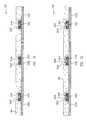
- FIG. 2Ashows an enlarged cross-sectional view of one embodiment of a pressure sensor die package 200 A in accordance with the invention.
- Pressure sensor die package 200 Aincludes a pressure sensor die 210 mounted on a substrate 202 in a die attach region 231 .
- pressure sensor die 210(FIG. 2A) includes a pressure sensitive micro-machine element 254 composed of a portion of the epitaxial silicon layer 216 .
- pressure sensor die 210is formed by bonding a substrate 218 to a glass or silicon wafer 220 .
- Substrate 218includes a cavity 222 such that when substrate 218 is bonded to wafer 220 , wafer 220 seals cavity 222 .
- Cavity 222is positioned directly below micro-machine element 254 .
- Pressure sensor die 210is attached to a first surface 211 (a die attach surface) of substrate 202 in die attach region 231 using any one of several well-known adhesives 204 .
- Substrate 202is typically a printed circuit board (PCB).
- electrically conductive pads 206 on first surface 230 of pressure sensor die 210are connected with electrically conductive bond wires 203 to electrically conductive traces 212 and/or electrically conductive regions (not shown) formed on first surface 211 of substrate 202 .
- electrically conductive vias 214are formed by methods well know to those of skill in the art.
- Electrically conductive vias 214are formed through substrate 202 , from traces 212 and/or regions on first surface 211 to a second surface (the mounting surface) 240 of substrate 202 which is opposite first surface 211 . Electrically conductive traces 213 formed on second surface 240 of substrate 202 extend to electrically conductive contacts or pads 215 formed on second surface 240 of substrate 202 . Electrically conductive pads 215 are used to connect substrate 202 and pressure sensor die 210 to a larger system, such as a mother board (not shown), using well known methods such as solder balls, pins, leadless carrier chip (LCC) contacts or other surface mounts.
- a mother boardnot shown
- pressure sensor die package 200 Aalso includes encapsulant 264 that forms, as discussed in more detail below, cavity 262 with sides 266 and 267 .
- cavity 262has length parallel to micro-machine element 254 of approximately 0.5 mm to 1.0 mm (19.7 mils to 39.4 mils) and a depth perpendicular to micro-machine element 254 that varies from application to application from 25 to 100 microns.
- Cavity 262is positioned directly over micro-machine element 254 .
- a bottom portion 263 of cavity 262is filled, according to the invention, with coupling gel 260 .
- Coupling gel 260is, in one embodiment, typically a silicon gel such as those produced by Dow Corning and well known to those of skill in the art.
- FIG. 2Bshows an enlarged cross-sectional view of a pressure sensor die package 200 B according to another embodiment of the invention.
- pressure sensor die 210 Bis a differential pressure sensor die.
- the operation of differential pressure sensors and differential pressure sensor dice, such as pressure sensor die 210 B,is well known to those of skill in the art. Therefore, the operation of differential sensor die 210 B will not be discussed in detail herein to avoid detracting from the invention.
- Pressure sensor die package 200 Bis identical to pressure sensor die package 200 A, discussed above with respect to FIG. 2A, except that pressure sensor die package 200 B includes a die hole 290 through wafer 220 to cavity 222 of sensor die 210 and a substrate through hole 292 through substrate 202 which is at least partially aligned with die hole 290 . Hole 290 die hole 290 and substrate through hole 292 allow pressure sensor die 210 to act as a differential pressure sensor.
- FIGS. 3A to 3 Lshow the significant steps involved in making one embodiment of a pressure sensor die package according to the invention.
- a method for making an absolute pressure sensor die packagesuch as pressure sensor die package 200 A in FIG. 2A, is shown in detail.
- substrate 502 in FIG. 5Adiscussed below
- substrate 202 in FIG. 2Ba standard substrate
- the method of the inventioncan be used to fabricate a differential pressure sensor package, such as differential pressure sensor package 200 B in FIG. 2B.
- a differential pressure sensor packagesuch as differential pressure sensor package 200 B in FIG. 2B.
- a method for making an absolute pressure sensor packageis discussed in detail below, and shown in FIGS. 3A to 3 L, for simplicity sake only and to keep the present discussion as brief and simple as possible. Consequently, the choice of this one embodiment of the invention for the discussion below is not meant to limit the scope of the present invention to this embodiment.
- FIG. 3Ashows a multi-package array sub-assembly 300 .
- Multi-package array sub-assembly 300includes substrate 302 made up of individual package substrate sections 302 A, 302 B and 302 C. Individual package substrate sections 302 A, 302 B and 302 C are identical to substrate 202 of FIG. 2A discussed above. As shown in FIG. 3A, each individual package substrate section 302 A, 302 B and 302 C has a pressure sensor die 310 A, 310 B and 310 C, respectively, mounted on a first surface 311 A, 311 B and 311 C, respectively.
- FIG. 3Bshows a lower mold section 370 of a custom mold used to fabricate pressure sensor die packages according to one embodiment of the invention.
- Lower mold section 370includes cavity 374 with cavity bottom surface 372 .
- FIG. 3Cshows multi-package array sub-assembly 300 positioned in cavity 374 of lower mold section 370 on cavity bottom surface 372 .
- FIG. 3Dshows multi-package array sub-assembly 300 positioned in cavity 374 of lower mold section 370 on cavity bottom surface 372 with upper mold section 376 positioned above lower mold section 370 .
- Upper mold section 376includes pins 378 A, 378 B and 378 C that extend from surface 379 of upper mold section 376 .
- FIG. 3Eshows upper mold section 376 positioned on lower mold section 370 just prior to introduction of encapsulant.
- pins 378 A, 378 B and 378 C of upper mold section 376make physical contact with micro-machine elements 354 A, 354 B and 354 C, respectively, of pressure sensor dice 310 A, 310 B and 310 C, respectively.
- a channel 375is formed for the introduction of liquid encapsulant.
- FIG. 3Fshows upper mold section 376 positioned on lower mold section 370 , as in FIG. 3E, with encapsulant 364 being introduced to the structure.
- FIG. 3Gshows upper mold section 376 positioned on lower mold section 370 , as in FIG. 3F, with encapsulant 364 having been introduced and flowed throughout the structure.
- encapsulant 364covers the entire first surfaces 311 A, 311 B and 311 C of individual package substrate sections 302 A, 302 B, 302 C, respectively, as well as the majority of pressure sensors 310 A, 310 B and 310 C.
- encapsulant 364is prevented for covering a first region of the first surfaces of pressure sensors 310 A, 310 B and 310 C including micro-machine elements 354 A, 354 B and 354 C by pins 378 A, 378 B and 378 C, respectively.
- FIG. 3Hshows upper mold section 376 removed from lower section 370 after molding.
- cavities 362 A, 362 B and 362 Care formed in encapsulant 364 such that a first region of the first surfaces of pressure sensors 310 A, 310 B and 310 C including micro-machine elements 354 A, 354 B and 354 C remain exposed at the bottom of cavities 362 A, 362 B and 362 C, respectively.
- FIG. 3Ishows multi-package array sub-assembly 300 removed from lower mold section 370 (FIG. 3G) after molding.
- each pressure sensor die 310 A, 310 B and 310 Chas a first region of the first surfaces of pressure sensors 310 A, 310 B and 310 C including micro-machine element 354 A, 354 B and 354 C, respectively, exposed to the environment at the bottom of cavities 362 A, 362 B and 362 C, respectively.
- FIG. 3Jshows multi-package array sub-assembly 300 of FIG. 3I with a coupling gel 360 A, 360 B and 360 C applied to, and filling a portion of, cavities 362 A, 362 B and 362 C, respectively.
- Coupling gel 360 A, 360 B and 360 Cprotects micro-machine elements 354 A, 354 B and 354 C, respectively, from the environment, yet is compressible and is capable of coupling pressure from the external environment to micro-machine elements 354 A, 354 B and 354 C, respectively.
- FIG. 3Kshows multi-package array sub-assembly 300 of FIG. 3J with solder balls 390 attached, thereby forming ball grid array pressure sensor die package array 399 including ball grid array pressure sensor packages 300 A, 300 B and 300 C.
- FIG. 3Lshows ball grid array pressure sensor package 300 B of FIG. 3K after singulation from multi-package array sub-assembly 300 .
- Singulation of ball grid array pressure sensor die package 300 Bis achieved by any singulation method such as sawing, laser or snapping methods.
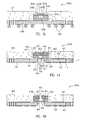
- FIG. 4Ashows an enlarged cross-sectional view of another embodiment of a pressure sensor die package 400 A in accordance with the invention.
- Pressure sensor die package 400 Aincludes a pressure sensor die 410 mounted on a substrate 402 .
- pressure sensor die 410(FIG. 4A) includes a pressure sensitive micro-machine element 454 composed of a portion of the epitaxial silicon layer 416 .
- pressure sensor die 410is formed by bonding a substrate 418 to a glass or silicon wafer 420 .
- Substrate 418includes a cavity 422 such that when substrate 418 is bonded to wafer 420 , wafer 420 seals cavity 422 .
- Cavity 422is positioned directly below micro-machine element 454 .
- pressure sensor die 410is attached to a first surface 411 (a die attach surface) of substrate 402 in a “flip-chip” configuration.
- Flip-chip configurationsare well known to those of skill in the art and are therefore not discussed in detail here to avoid detracting from the invention.
- an under fill material 404is applied between first surface 411 and pressure sensor die 410 .
- Under filling and under fill materialsare well known to those of skill in the art.
- Substrate 402is typically a printed circuit board (PCB) that, as discussed in more detail below, is customized according to the invention for flip-chip applications of pressure sensor die 410 .
- substrate 402includes pre-cut hole 462 with sides 466 and 467 .
- hole 462has a length of 1.0 mm (39.4 mils) and a width of 1.0 mm (39.4 mils).
- Hole 462is positioned directly over micro-machine element 454 and a first region of a first surface 430 of pressure sensor die 410 .
- a bottom portion 463 of hole 462is, according to the invention, filled with coupling gel 460 .
- Coupling gel 460protects micro-machine element 454 from the environment, yet is compressible and is capable of coupling pressure from the external environment to micro-machine element 454 .
- Coupling gel 460is, in one embodiment, typically a silicon gel such as those produced by Dow Corning and well known to those of skill in the art.
- electrically conductive pads 406 first surface 430 of pressure sensor die 410are connected directly to electrically conductive traces 412 and/or electrically conductive regions (not shown) formed on first surface 411 of substrate 402 .
- electrically conductive vias 414are formed through substrate 402 , from traces 412 and/or regions on first surface 411 to a second surface (the mounting surface) 440 of substrate 402 which is opposite first surface 411 .
- Electrically conductive traces 413 formed on second surface 440 of substrate 402extend to electrically conductive contacts or pads 415 formed on second surface 440 of substrate 402 .
- Electrically conductive pads 415are used to connect substrate 402 and pressure sensor die 410 to a larger system, such as a mother board (not shown), using well known methods such as solder balls, pins, leadless carrier chip (LCC) contacts or other surface mounts.
- pressure sensor die package 400 Aalso includes encapsulant 464 that protects pressure sensor die 410 and first surface 411 of substrate 402 from the elements.
- FIG. 4Bshows an enlarged cross-sectional view of a pressure sensor die package 400 B according to another embodiment of the invention.
- pressure sensor die 410 Bis a differential pressure sensor die.
- the operation of differential pressure sensors and differential pressure sensor dice, such as pressure sensor die 410 B,is well known to those of skill in the art. Therefore, the operation of differential sensor die 410 B will not be discussed in detail herein to avoid detracting from the invention.
- Pressure sensor die package 400 Bis identical to pressure sensor die package 400 A, discussed above with respect to FIG. 4A, except that pressure sensor die package 400 B includes a die hole 490 through wafer 420 to cavity 422 of sensor die 410 and encapsulant through hole 492 through encapsulant 464 which is at least partially aligned with die hole 490 .
- Through hole 490allows pressure sensor die 410 to act as a differential pressure sensor package.
- FIGS. 5A to 5 Mshow the significant steps involved for making one embodiment of a pressure sensor package according to the invention.
- a method for making an absolute pressure sensor die packagesuch as pressure sensor die package 400 A in FIG. 4A, is discussed in detail.
- a custom moldsuch as mold 370 and 376 in FIG. 3E (discussed above), or by forming cutting an encapsulation through hole 492 in encapsulant 464 in FIG.
- the method of the inventioncan be used to fabricate a differential pressure sensor die package, such as differential pressure sensor die package 400 B in FIG. 4B.
- a method for making an absolute pressure sensor packageis discussed in detail below, and shown in FIGS. 5A to 5 M, for simplicity sake only and to keep the present discussion as brief and simple as possible. Consequently, the choice of this one embodiment of the invention for the discussion below is not meant to limit the scope of the present invention to this embodiment.
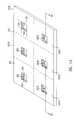
- FIG. 5Ashows a multi-package array substrate 502 customized according to the invention to include substrate holes 462 , 560 , 561 , 562 A, 562 B and 562 C.
- multi-package array substrate 502is a PCB and includes substrate 402 of FIG. 4A with hole 462 having sides 467 and 466 .
- multi-package array substrate 502includes substrates 502 A, 502 B, 502 C, 502 D and 502 E that are discussed in more detail below.
- Holes 462 , 560 , 561 , 562 A, 562 B and 562 Care formed by methods well know to those of skill in the art such as punching the holes bore firing.
- hole,s 462 , 560 , 561 , 562 A, 562 B and 562 Chave a length 593 of 1.0 mm (39.4 mils) and a width 595 of 1.0 mm (39.4 mils).
- multi-package array substrate 502includes a nine by nine (9 ⁇ 9) array of substrates such as substrates 402 , 502 A, 502 B, 502 C, 502 D and 502 E.
- multi-package array substrate 502can include any number of substrates such as substrates 402 , 502 A, 502 B, 502 C, 502 D and 502 E. Only six such substrates are shown in FIG. 5A for simplicity sake.
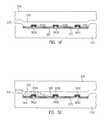
- FIG. 5Bshows a multi-package array sub-assembly 500 .
- Multi-package array sub-assembly 500includes multi-package array substrate 502 , as seen along line 5 B— 5 B of FIG. 5A, made up of individual package substrates 502 A, 502 B and 502 C. Individual package substrates 502 A, 502 B and 502 C are identical to substrate 402 of FIG. 4A discussed above. As shown in FIG. 5B, each individual package substrate 502 A, 502 B and 502 C has a pressure sensor die 510 A, 510 B and 510 C, respectively, mounted on a first surface 511 A, 511 B and 511 C, respectively, in a flip-chip configuration.
- FIG. 5Cshows a lower mold section 570 of a mold used to fabricate pressure sensor die packages according to one embodiment of the invention.
- Lower mold section 570includes cavity 574 with cavity bottom surface 572 .
- FIG. 5Dshows multi-package array sub-assembly 500 positioned in cavity 574 of lower mold section 570 on cavity bottom surface 572 .
- FIG. 5Eshows multi-package array sub-assembly 500 positioned in cavity 574 of lower mold section 570 on cavity bottom surface 572 with upper mold section 576 positioned above lower mold section 570 .
- FIG. 5Fshows upper mold section 576 positioned on lower mold section 570 just prior to introduction of encapsulant. As shown in FIG. 5F, when upper mold section 576 is in place on lower mold section 570 , a channel 575 is formed for the introduction of liquid encapsulant.
- FIG. 5Gshows upper mold section 576 positioned on lower mold section 570 , as in FIG. 5F, with encapsulant 564 being introduced to the structure.
- FIG. 5Hshows upper mold section 576 positioned on lower mold section 570 , as in FIG. 5G, with encapsulant 564 having been introduced and flowed throughout the structure.
- encapsulant 564covers the entire first surfaces 511 A, 511 B and 511 C of individual package substrates 502 A, 502 B, 502 C, respectively, as well as pressure sensor dice 510 A, 510 B and 510 C.
- FIG. 5Ishows upper mold section 576 removed from lower section 570 after molding.
- holes 562 A, 562 B and 562 C of substrates 502 A, 502 B 502 Care positioned such that micro-machine elements 554 A, 554 B and 554 C remain exposed at the bottom of holes 562 A, 562 B and 562 C, respectively.
- FIG. 5Jshows multi-package array sub-assembly 500 removed from lower mold section 570 (FIG. 5H) after molding.
- each pressure sensor die 510 A, 510 B and 510 Chas its micro-machine element 554 A, 554 B and 554 C, respectively, exposed to the environment at the bottom of holes 562 A, 562 B and 562 C, respectively.
- FIG. 5Kshows multi-package array sub-assembly 500 of FIG. 5J with a coupling gel 560 A, 560 B and 560 C applied to, and filling a portion, of holes 562 A, 562 B and 562 C, respectively.
- Coupling gel 560 A, 560 B and 560 Cprotects micro-machine elements 554 A, 554 B and 554 C, respectively, from the environment, yet is compressible and is capable of coupling pressure from the external environment to micro-machine elements 554 A, 554 B and 554 C, respectively.
- FIG. 5Lshows multi-package array sub-assembly 500 of FIG. 5K with solder balls 590 attached, thereby forming ball grid array pressure sensor die array 599 including ball grid array pressure sensor die packages 500 A, 500 B and 500 C.
- FIG. 5Mshows ball grid array pressure sensor die package 500 B of FIG. 5L after singulation from multi-package array sub-assembly 500 .
- Singulation of ball grid array pressure sensor die package 500 Bis achieved by any singulation method such as sawing, laser or snapping methods.
- FIGS. 3A to 3 L and FIGS. 5A to 5 Mshow a method for making an absolute pressure sensor die package.
- the method of the inventioncan be used to fabricate a differential pressure sensor package.
- a method for making an absolute pressure sensor packageis discussed in detail above, and shown in FIGS. 3A to 3 L and 5 A to 5 M, for simplicity sake only and to keep the present discussion as brief and simple as possible.
- the scope of the inventionis at least as broad as given by the following claims.
Landscapes
- Physics & Mathematics (AREA)
- General Physics & Mathematics (AREA)
- Engineering & Computer Science (AREA)
- Microelectronics & Electronic Packaging (AREA)
- Condensed Matter Physics & Semiconductors (AREA)
- Computer Hardware Design (AREA)
- Power Engineering (AREA)
- Chemical & Material Sciences (AREA)
- Analytical Chemistry (AREA)
- Manufacturing & Machinery (AREA)
- Measuring Fluid Pressure (AREA)
Abstract
Description
Claims (28)
Priority Applications (1)
| Application Number | Priority Date | Filing Date | Title |
|---|---|---|---|
| US09/754,393US6441503B1 (en) | 2001-01-03 | 2001-01-03 | Bond wire pressure sensor die package |
Applications Claiming Priority (1)
| Application Number | Priority Date | Filing Date | Title |
|---|---|---|---|
| US09/754,393US6441503B1 (en) | 2001-01-03 | 2001-01-03 | Bond wire pressure sensor die package |
Publications (1)
| Publication Number | Publication Date |
|---|---|
| US6441503B1true US6441503B1 (en) | 2002-08-27 |
Family
ID=25034599
Family Applications (1)
| Application Number | Title | Priority Date | Filing Date |
|---|---|---|---|
| US09/754,393Expired - LifetimeUS6441503B1 (en) | 2001-01-03 | 2001-01-03 | Bond wire pressure sensor die package |
Country Status (1)
| Country | Link |
|---|---|
| US (1) | US6441503B1 (en) |
Cited By (56)
| Publication number | Priority date | Publication date | Assignee | Title |
|---|---|---|---|---|
| US20030186482A1 (en)* | 2001-05-11 | 2003-10-02 | Melexis Nv Microelectronic Integrated Systems | Integrated sensor packages and methods of making the same |
| US6660559B1 (en) | 2001-06-25 | 2003-12-09 | Amkor Technology, Inc. | Method of making a chip carrier package using laser ablation |
| US20040053447A1 (en)* | 2001-06-29 | 2004-03-18 | Foster Donald Craig | Leadframe having fine pitch bond fingers formed using laser cutting method |
| US20040112138A1 (en)* | 2002-12-16 | 2004-06-17 | Knirck Jeffrey G. | Measuring pressure exerted by a rigid surface |
| US20040197954A1 (en)* | 2003-04-07 | 2004-10-07 | Walter Moden | Chip scale image sensor semiconductor package and method of fabrication |
| US20050062121A1 (en)* | 2003-09-24 | 2005-03-24 | Inao Toyoda | Sensor device having thin membrane and method of manufacturing the same |
| US20050190152A1 (en)* | 2003-12-29 | 2005-09-01 | Vladimir Vaganov | Three-dimensional analog input control device |
| US20060196412A1 (en)* | 2005-03-03 | 2006-09-07 | Atmel Germany Gmbh | Method and casting mold for producing an optical semiconductor module |
| US7145253B1 (en)* | 2004-06-09 | 2006-12-05 | Amkor Technology, Inc. | Encapsulated sensor device |
| US20070126130A1 (en)* | 2005-11-14 | 2007-06-07 | Alfons Dehe | Sensor Module And Method For Manufacturing Same |
| US20070222005A1 (en)* | 2006-03-13 | 2007-09-27 | Infineon Technologies Ag | Integrated circuit having a semiconductor sensor device and method for producing the same |
| US20070264743A1 (en)* | 2004-12-28 | 2007-11-15 | Vladimir Vaganov | Semiconductor input control device |
| EP1901050A2 (en) | 2005-05-09 | 2008-03-19 | Delphi Technologies, Inc. | Pressure transducer |
| US20090007679A1 (en)* | 2007-07-03 | 2009-01-08 | Endotronix, Inc. | Wireless pressure sensor and method for fabricating wireless pressure sensor for integration with an implantable device |
| US20090020862A1 (en)* | 2007-05-30 | 2009-01-22 | Industrial Technology Research Institute | Device structure with preformed ring and method therefor |
| US20090212377A1 (en)* | 2003-12-29 | 2009-08-27 | Vladimir Vaganov | Semiconductor input control device |
| US7632698B2 (en) | 2006-05-16 | 2009-12-15 | Freescale Semiconductor, Inc. | Integrated circuit encapsulation and method therefor |
| US7781852B1 (en)* | 2006-12-05 | 2010-08-24 | Amkor Technology, Inc. | Membrane die attach circuit element package and method therefor |
| US20100242605A1 (en)* | 2009-03-27 | 2010-09-30 | Klaus Offterdinger | Sensor component |
| US20100317139A1 (en)* | 2003-12-29 | 2010-12-16 | Vladimir Vaganov | Three-dimensional force input control device and fabrication |
| CN101337652B (en)* | 2008-08-11 | 2011-08-10 | 美新半导体(无锡)有限公司 | Packaging of contact surface of sensor element and packaging method thereof |
| US8350345B2 (en) | 2003-12-29 | 2013-01-08 | Vladimir Vaganov | Three-dimensional input control device |
| US20130175527A1 (en)* | 2012-01-09 | 2013-07-11 | Infineon Technologies Ag | Sensor arrangement, a measurement circuit, chip-packages and a method for forming a sensor arrangement |
| US8617934B1 (en) | 2000-11-28 | 2013-12-31 | Knowles Electronics, Llc | Methods of manufacture of top port multi-part surface mount silicon condenser microphone packages |
| US8624386B1 (en) | 2000-11-28 | 2014-01-07 | Knowles Electronics, Llc | Bottom port multi-part surface mount silicon condenser microphone package |
| US20140084478A1 (en)* | 2012-09-26 | 2014-03-27 | Bogdan M. Simion | Mold chase for integrated circuit package assembly and associated techniques and configurations |
| US9034666B2 (en) | 2003-12-29 | 2015-05-19 | Vladimir Vaganov | Method of testing of MEMS devices on a wafer level |
| US9078063B2 (en) | 2012-08-10 | 2015-07-07 | Knowles Electronics, Llc | Microphone assembly with barrier to prevent contaminant infiltration |
| DE102014208100A1 (en)* | 2014-04-29 | 2015-10-29 | Robert Bosch Gmbh | sensor arrangement |
| JP2016045049A (en)* | 2014-08-21 | 2016-04-04 | 株式会社テージーケー | Pressure sensor module and manufacturing method of pressure sensor module |
| US20160116359A1 (en)* | 2014-10-28 | 2016-04-28 | Lingsen Precision Industries, Ltd. | Pressure sensor package |
| US9374643B2 (en) | 2011-11-04 | 2016-06-21 | Knowles Electronics, Llc | Embedded dielectric as a barrier in an acoustic device and method of manufacture |
| US9598280B2 (en)* | 2014-11-10 | 2017-03-21 | Nxp Usa, Inc. | Environmental sensor structure |
| DE102015116081A1 (en)* | 2015-09-23 | 2017-03-23 | Infineon Technologies Ag | An electronic sensor device comprising a flip-chip mounted semiconductor chip and a substrate having an opening |
| US20170101307A1 (en)* | 2015-10-08 | 2017-04-13 | Samsung Electro-Mechanics Co., Ltd. | Semiconductor package |
| WO2017147234A1 (en)* | 2016-02-24 | 2017-08-31 | Honeywell International Inc. | Flip chip pressure sensor assembly |
| US9794661B2 (en) | 2015-08-07 | 2017-10-17 | Knowles Electronics, Llc | Ingress protection for reducing particle infiltration into acoustic chamber of a MEMS microphone package |
| US20180174935A1 (en)* | 2016-12-13 | 2018-06-21 | Infineon Technologies Ag | Semiconductor package and method for fabricating a semiconductor package |
| US20190206752A1 (en)* | 2017-12-29 | 2019-07-04 | Texas Instruments Incorporated | Integrated circuit packages with cavities and methods of manufacturing the same |
| US10430624B2 (en) | 2017-02-24 | 2019-10-01 | Endotronix, Inc. | Wireless sensor reader assembly |
| US10481024B2 (en) | 2017-04-20 | 2019-11-19 | Honeywell International Inc. | Pressure sensor assembly including a cured elastomeric force transmitting member |
| US20200182715A1 (en)* | 2018-12-05 | 2020-06-11 | 4Iiii Innovations Inc. | Adhesive strain sensing pods |
| US10684184B2 (en)* | 2017-04-20 | 2020-06-16 | Honeywell International Inc. | Pressure sensor assembly having a cavity filled with gel or fluid |
| US10964623B2 (en)* | 2015-04-22 | 2021-03-30 | Zf Friedrichshafen Ag | Electronic module and method for encapsulation thereof |
| US11047753B2 (en) | 2018-12-27 | 2021-06-29 | Therm-O-Disc, Incorporated | Pressure sensor assembly and method for manufacturing a pressure sensor assembly |
| US11225409B2 (en) | 2018-09-17 | 2022-01-18 | Invensense, Inc. | Sensor with integrated heater |
| WO2022132042A1 (en)* | 2020-12-14 | 2022-06-23 | Ams Sensors Singapore Pte. Ltd. | Wafer-level manufacture of optical packages |
| US11397120B2 (en)* | 2020-09-23 | 2022-07-26 | Apple Inc. | Interface pressure sensor system for electronic device |
| US20220254720A1 (en)* | 2021-02-05 | 2022-08-11 | Changxin Memory Technologies, Inc. | Package substrate and semiconductor structure with same |
| US11506549B2 (en)* | 2019-01-24 | 2022-11-22 | Coretronic Mems Corporation | Force sensor |
| US20220396474A1 (en)* | 2021-06-11 | 2022-12-15 | Texas Instruments Incorporated | Semiconductor package with metal column mold barrier |
| US11615257B2 (en) | 2017-02-24 | 2023-03-28 | Endotronix, Inc. | Method for communicating with implant devices |
| US20230129699A1 (en)* | 2021-10-22 | 2023-04-27 | Texas Instruments Incorporated | Ic package with interface region |
| US11839450B2 (en) | 2020-09-23 | 2023-12-12 | Apple Inc. | Pressure sensor module for wearable applanation tonometer |
| US11839451B2 (en) | 2020-09-23 | 2023-12-12 | Apple Inc. | Sensing structure for pulse-wave velocity measurement |
| US12293964B2 (en) | 2021-02-05 | 2025-05-06 | Changxin Memory Technologies, Inc. | Package substrate and semiconductor structure with package substrate |
Citations (25)
| Publication number | Priority date | Publication date | Assignee | Title |
|---|---|---|---|---|
| US3748571A (en) | 1972-09-07 | 1973-07-24 | Kulite Semiconductors Products | Pressure sensitive transducers employing capacitive and resistive variations |
| US4874500A (en)* | 1987-07-15 | 1989-10-17 | Sri International | Microelectrochemical sensor and sensor array |
| US5037779A (en) | 1989-05-19 | 1991-08-06 | Whalley Peter D | Method of encapsulating a sensor device using capillary action and the device so encapsulated |
| US5096851A (en) | 1988-05-19 | 1992-03-17 | Semiconductor Energy Laboratory Co., Ltd. | Method of packaging an electronic device using a common holder to carry the device in both a cvd and molding step |
| US5148266A (en) | 1990-09-24 | 1992-09-15 | Ist Associates, Inc. | Semiconductor chip assemblies having interposer and flexible lead |
| US5173836A (en) | 1992-03-05 | 1992-12-22 | Motorola, Inc. | Hermetically sealed interface |
| US5177661A (en) | 1989-01-13 | 1993-01-05 | Kopin Corporation | SOI diaphgram sensor |
| US5296730A (en) | 1992-01-16 | 1994-03-22 | Oki Electric Industry Co., Ltd. | Semiconductor pressure sensor for sensing pressure applied thereto |
| US5438877A (en) | 1994-06-13 | 1995-08-08 | Motorola, Inc. | Pressure sensor package for reducing stress-induced measurement error |
| US5635671A (en) | 1994-03-16 | 1997-06-03 | Amkor Electronics, Inc. | Mold runner removal from a substrate-based packaged electronic device |
| US5719069A (en) | 1994-09-14 | 1998-02-17 | Delco Electronics Corporation | One-chip integrated sensor process |
| US5721446A (en) | 1995-01-19 | 1998-02-24 | Mitsubishi Denki Kabushiki Kaisha | Semiconductor pressure sensor with spacing member disposed between sensor and substrate |
| US5852320A (en) | 1996-02-19 | 1998-12-22 | Mitsubishi Denki Kabushiki Kaisha | Semiconductor sensor with protective cap covering exposed conductive through-holes |
| US5981361A (en) | 1996-09-13 | 1999-11-09 | Fujitsu Limited | Fabrication process of a semiconductor device including a dicing process of a semiconductor wafer |
| US6140144A (en)* | 1996-08-08 | 2000-10-31 | Integrated Sensing Systems, Inc. | Method for packaging microsensors |
| US6150681A (en) | 1998-07-24 | 2000-11-21 | Silicon Microstructures, Inc. | Monolithic flow sensor and pressure sensor |
| US6155119A (en)* | 1996-02-16 | 2000-12-05 | Ami Doduco Gmbh | Arrangement comprising an electrical printed-circuit board and an electrical pressure pick-up |
| US6201285B1 (en) | 1997-07-04 | 2001-03-13 | Kabushiki Kaisha Tokai Rika Denki Seisakusho | Sensor with diaphragm sensor chip |
| US6229190B1 (en) | 1998-12-18 | 2001-05-08 | Maxim Integrated Products, Inc. | Compensated semiconductor pressure sensor |
| US6255728B1 (en) | 1999-01-15 | 2001-07-03 | Maxim Integrated Products, Inc. | Rigid encapsulation package for semiconductor devices |
| US6254815B1 (en) | 1994-07-29 | 2001-07-03 | Motorola, Inc. | Molded packaging method for a sensing die having a pressure sensing diaphragm |
| US6278167B1 (en) | 1998-08-14 | 2001-08-21 | Infineon Technologies Ag | Semiconductor sensor with a base element and at least one deformation element |
| US6326682B1 (en) | 1998-12-21 | 2001-12-04 | Kulite Semiconductor Products | Hermetically sealed transducer and methods for producing the same |
| US6338985B1 (en) | 2000-02-04 | 2002-01-15 | Amkor Technology, Inc. | Making chip size semiconductor packages |
| US6346742B1 (en) | 1998-11-12 | 2002-02-12 | Maxim Integrated Products, Inc. | Chip-scale packaged pressure sensor |
- 2001
- 2001-01-03USUS09/754,393patent/US6441503B1/ennot_activeExpired - Lifetime
Patent Citations (25)
| Publication number | Priority date | Publication date | Assignee | Title |
|---|---|---|---|---|
| US3748571A (en) | 1972-09-07 | 1973-07-24 | Kulite Semiconductors Products | Pressure sensitive transducers employing capacitive and resistive variations |
| US4874500A (en)* | 1987-07-15 | 1989-10-17 | Sri International | Microelectrochemical sensor and sensor array |
| US5096851A (en) | 1988-05-19 | 1992-03-17 | Semiconductor Energy Laboratory Co., Ltd. | Method of packaging an electronic device using a common holder to carry the device in both a cvd and molding step |
| US5177661A (en) | 1989-01-13 | 1993-01-05 | Kopin Corporation | SOI diaphgram sensor |
| US5037779A (en) | 1989-05-19 | 1991-08-06 | Whalley Peter D | Method of encapsulating a sensor device using capillary action and the device so encapsulated |
| US5148266A (en) | 1990-09-24 | 1992-09-15 | Ist Associates, Inc. | Semiconductor chip assemblies having interposer and flexible lead |
| US5296730A (en) | 1992-01-16 | 1994-03-22 | Oki Electric Industry Co., Ltd. | Semiconductor pressure sensor for sensing pressure applied thereto |
| US5173836A (en) | 1992-03-05 | 1992-12-22 | Motorola, Inc. | Hermetically sealed interface |
| US5635671A (en) | 1994-03-16 | 1997-06-03 | Amkor Electronics, Inc. | Mold runner removal from a substrate-based packaged electronic device |
| US5438877A (en) | 1994-06-13 | 1995-08-08 | Motorola, Inc. | Pressure sensor package for reducing stress-induced measurement error |
| US6254815B1 (en) | 1994-07-29 | 2001-07-03 | Motorola, Inc. | Molded packaging method for a sensing die having a pressure sensing diaphragm |
| US5719069A (en) | 1994-09-14 | 1998-02-17 | Delco Electronics Corporation | One-chip integrated sensor process |
| US5721446A (en) | 1995-01-19 | 1998-02-24 | Mitsubishi Denki Kabushiki Kaisha | Semiconductor pressure sensor with spacing member disposed between sensor and substrate |
| US6155119A (en)* | 1996-02-16 | 2000-12-05 | Ami Doduco Gmbh | Arrangement comprising an electrical printed-circuit board and an electrical pressure pick-up |
| US5852320A (en) | 1996-02-19 | 1998-12-22 | Mitsubishi Denki Kabushiki Kaisha | Semiconductor sensor with protective cap covering exposed conductive through-holes |
| US6140144A (en)* | 1996-08-08 | 2000-10-31 | Integrated Sensing Systems, Inc. | Method for packaging microsensors |
| US5981361A (en) | 1996-09-13 | 1999-11-09 | Fujitsu Limited | Fabrication process of a semiconductor device including a dicing process of a semiconductor wafer |
| US6201285B1 (en) | 1997-07-04 | 2001-03-13 | Kabushiki Kaisha Tokai Rika Denki Seisakusho | Sensor with diaphragm sensor chip |
| US6150681A (en) | 1998-07-24 | 2000-11-21 | Silicon Microstructures, Inc. | Monolithic flow sensor and pressure sensor |
| US6278167B1 (en) | 1998-08-14 | 2001-08-21 | Infineon Technologies Ag | Semiconductor sensor with a base element and at least one deformation element |
| US6346742B1 (en) | 1998-11-12 | 2002-02-12 | Maxim Integrated Products, Inc. | Chip-scale packaged pressure sensor |
| US6229190B1 (en) | 1998-12-18 | 2001-05-08 | Maxim Integrated Products, Inc. | Compensated semiconductor pressure sensor |
| US6326682B1 (en) | 1998-12-21 | 2001-12-04 | Kulite Semiconductor Products | Hermetically sealed transducer and methods for producing the same |
| US6255728B1 (en) | 1999-01-15 | 2001-07-03 | Maxim Integrated Products, Inc. | Rigid encapsulation package for semiconductor devices |
| US6338985B1 (en) | 2000-02-04 | 2002-01-15 | Amkor Technology, Inc. | Making chip size semiconductor packages |
Cited By (124)
| Publication number | Priority date | Publication date | Assignee | Title |
|---|---|---|---|---|
| US8623709B1 (en) | 2000-11-28 | 2014-01-07 | Knowles Electronics, Llc | Methods of manufacture of top port surface mount silicon condenser microphone packages |
| US8623710B1 (en) | 2000-11-28 | 2014-01-07 | Knowles Electronics, Llc | Methods of manufacture of bottom port multi-part surface mount silicon condenser microphone packages |
| US9040360B1 (en) | 2000-11-28 | 2015-05-26 | Knowles Electronics, Llc | Methods of manufacture of bottom port multi-part surface mount MEMS microphones |
| US9024432B1 (en) | 2000-11-28 | 2015-05-05 | Knowles Electronics, Llc | Bottom port multi-part surface mount MEMS microphone |
| US9023689B1 (en) | 2000-11-28 | 2015-05-05 | Knowles Electronics, Llc | Top port multi-part surface mount MEMS microphone |
| US9006880B1 (en) | 2000-11-28 | 2015-04-14 | Knowles Electronics, Llc | Top port multi-part surface mount silicon condenser microphone |
| US8765530B1 (en) | 2000-11-28 | 2014-07-01 | Knowles Electronics, Llc | Methods of manufacture of top port surface mount silicon condenser microphone packages |
| US9061893B1 (en) | 2000-11-28 | 2015-06-23 | Knowles Electronics, Llc | Methods of manufacture of top port multi-part surface mount silicon condenser microphones |
| US8704360B1 (en) | 2000-11-28 | 2014-04-22 | Knowles Electronics, Llc | Top port surface mount silicon condenser microphone package |
| US9067780B1 (en) | 2000-11-28 | 2015-06-30 | Knowles Electronics, Llc | Methods of manufacture of top port surface mount MEMS microphones |
| US8652883B1 (en) | 2000-11-28 | 2014-02-18 | Knowles Electronics, Llc | Methods of manufacture of bottom port surface mount silicon condenser microphone packages |
| US9150409B1 (en) | 2000-11-28 | 2015-10-06 | Knowles Electronics, Llc | Methods of manufacture of bottom port surface mount MEMS microphones |
| US8629005B1 (en) | 2000-11-28 | 2014-01-14 | Knowles Electronics, Llc | Methods of manufacture of bottom port surface mount silicon condenser microphone packages |
| US8629551B1 (en) | 2000-11-28 | 2014-01-14 | Knowles Electronics, Llc | Bottom port surface mount silicon condenser microphone package |
| US8629552B1 (en) | 2000-11-28 | 2014-01-14 | Knowles Electronics, Llc | Top port multi-part surface mount silicon condenser microphone package |
| US8624384B1 (en) | 2000-11-28 | 2014-01-07 | Knowles Electronics, Llc | Bottom port surface mount silicon condenser microphone package |
| US8624385B1 (en) | 2000-11-28 | 2014-01-07 | Knowles Electronics, Llc | Top port surface mount silicon condenser microphone package |
| US9051171B1 (en) | 2000-11-28 | 2015-06-09 | Knowles Electronics, Llc | Bottom port surface mount MEMS microphone |
| US8624387B1 (en) | 2000-11-28 | 2014-01-07 | Knowles Electronics, Llc | Top port multi-part surface mount silicon condenser microphone package |
| US8624386B1 (en) | 2000-11-28 | 2014-01-07 | Knowles Electronics, Llc | Bottom port multi-part surface mount silicon condenser microphone package |
| US8617934B1 (en) | 2000-11-28 | 2013-12-31 | Knowles Electronics, Llc | Methods of manufacture of top port multi-part surface mount silicon condenser microphone packages |
| US9096423B1 (en) | 2000-11-28 | 2015-08-04 | Knowles Electronics, Llc | Methods of manufacture of top port multi-part surface mount MEMS microphones |
| US9133020B1 (en) | 2000-11-28 | 2015-09-15 | Knowles Electronics, Llc | Methods of manufacture of bottom port surface mount MEMS microphones |
| US10321226B2 (en) | 2000-11-28 | 2019-06-11 | Knowles Electronics, Llc | Top port multi-part surface mount MEMS microphone |
| US9139422B1 (en) | 2000-11-28 | 2015-09-22 | Knowles Electronics, Llc | Bottom port surface mount MEMS microphone |
| US9980038B2 (en) | 2000-11-28 | 2018-05-22 | Knowles Electronics, Llc | Top port multi-part surface mount silicon condenser microphone |
| US9139421B1 (en) | 2000-11-28 | 2015-09-22 | Knowles Electronics, Llc | Top port surface mount MEMS microphone |
| US9156684B1 (en) | 2000-11-28 | 2015-10-13 | Knowles Electronics, Llc | Methods of manufacture of top port surface mount MEMS microphones |
| US8633064B1 (en) | 2000-11-28 | 2014-01-21 | Knowles Electronics, Llc | Methods of manufacture of top port multipart surface mount silicon condenser microphone package |
| US9148731B1 (en) | 2000-11-28 | 2015-09-29 | Knowles Electronics, Llc | Top port surface mount MEMS microphone |
| US9338560B1 (en) | 2000-11-28 | 2016-05-10 | Knowles Electronics, Llc | Top port multi-part surface mount silicon condenser microphone |
| US20030186482A1 (en)* | 2001-05-11 | 2003-10-02 | Melexis Nv Microelectronic Integrated Systems | Integrated sensor packages and methods of making the same |
| US6762077B2 (en)* | 2001-05-11 | 2004-07-13 | Melexis Nv | Integrated sensor packages and methods of making the same |
| US20040197957A1 (en)* | 2001-05-11 | 2004-10-07 | Melexis Nv | Integrated sensor packages and methods of making the same |
| US6917089B2 (en) | 2001-05-11 | 2005-07-12 | Melexis Nv | Integrated sensor packages and methods of making the same |
| US6660559B1 (en) | 2001-06-25 | 2003-12-09 | Amkor Technology, Inc. | Method of making a chip carrier package using laser ablation |
| US20040053447A1 (en)* | 2001-06-29 | 2004-03-18 | Foster Donald Craig | Leadframe having fine pitch bond fingers formed using laser cutting method |
| US20040112138A1 (en)* | 2002-12-16 | 2004-06-17 | Knirck Jeffrey G. | Measuring pressure exerted by a rigid surface |
| US6931938B2 (en) | 2002-12-16 | 2005-08-23 | Jeffrey G. Knirck | Measuring pressure exerted by a rigid surface |
| US7215015B2 (en) | 2003-04-07 | 2007-05-08 | Micron Technology, Inc. | Imaging system |
| US20040197954A1 (en)* | 2003-04-07 | 2004-10-07 | Walter Moden | Chip scale image sensor semiconductor package and method of fabrication |
| US20040214372A1 (en)* | 2003-04-07 | 2004-10-28 | Walter Moden | Method for fabricating image sensor semiconductor package |
| US20050003579A1 (en)* | 2003-04-07 | 2005-01-06 | Walter Moden | Imaging system |
| US6917090B2 (en)* | 2003-04-07 | 2005-07-12 | Micron Technology, Inc. | Chip scale image sensor package |
| US6969632B2 (en)* | 2003-04-07 | 2005-11-29 | Micron Technology, Inc. | Method for fabricating image sensor semiconductor package |
| US7211873B2 (en)* | 2003-09-24 | 2007-05-01 | Denso Corporation | Sensor device having thin membrane and method of manufacturing the same |
| US20050062121A1 (en)* | 2003-09-24 | 2005-03-24 | Inao Toyoda | Sensor device having thin membrane and method of manufacturing the same |
| US8350345B2 (en) | 2003-12-29 | 2013-01-08 | Vladimir Vaganov | Three-dimensional input control device |
| US8004052B2 (en) | 2003-12-29 | 2011-08-23 | Vladimir Vaganov | Three-dimensional analog input control device |
| US7554167B2 (en) | 2003-12-29 | 2009-06-30 | Vladimir Vaganov | Three-dimensional analog input control device |
| US9034666B2 (en) | 2003-12-29 | 2015-05-19 | Vladimir Vaganov | Method of testing of MEMS devices on a wafer level |
| US7880247B2 (en)* | 2003-12-29 | 2011-02-01 | Vladimir Vaganov | Semiconductor input control device |
| US20090212377A1 (en)* | 2003-12-29 | 2009-08-27 | Vladimir Vaganov | Semiconductor input control device |
| US20050190152A1 (en)* | 2003-12-29 | 2005-09-01 | Vladimir Vaganov | Three-dimensional analog input control device |
| US20090237275A1 (en)* | 2003-12-29 | 2009-09-24 | Vladimir Vaganov | Three-dimensional analog input control device |
| US20100317139A1 (en)* | 2003-12-29 | 2010-12-16 | Vladimir Vaganov | Three-dimensional force input control device and fabrication |
| US8053267B2 (en) | 2003-12-29 | 2011-11-08 | Vladimir Vaganov | Three-dimensional force input control device and fabrication |
| US7145253B1 (en)* | 2004-06-09 | 2006-12-05 | Amkor Technology, Inc. | Encapsulated sensor device |
| US20070264743A1 (en)* | 2004-12-28 | 2007-11-15 | Vladimir Vaganov | Semiconductor input control device |
| US7476952B2 (en)* | 2004-12-28 | 2009-01-13 | Vladimir Vaganov | Semiconductor input control device |
| US20060196412A1 (en)* | 2005-03-03 | 2006-09-07 | Atmel Germany Gmbh | Method and casting mold for producing an optical semiconductor module |
| US7740465B2 (en)* | 2005-03-03 | 2010-06-22 | Atmel Automotive Gmbh | Casting mold for producing an optical semiconductor module |
| EP1901050A3 (en)* | 2005-05-09 | 2009-09-16 | Delphi Technologies, Inc. | Pressure transducer |
| EP1901050A2 (en) | 2005-05-09 | 2008-03-19 | Delphi Technologies, Inc. | Pressure transducer |
| US7994618B2 (en)* | 2005-11-14 | 2011-08-09 | Infineon Technologies Ag | Sensor module and method for manufacturing same |
| US20070126130A1 (en)* | 2005-11-14 | 2007-06-07 | Alfons Dehe | Sensor Module And Method For Manufacturing Same |
| US20070222005A1 (en)* | 2006-03-13 | 2007-09-27 | Infineon Technologies Ag | Integrated circuit having a semiconductor sensor device and method for producing the same |
| US7964954B2 (en)* | 2006-03-13 | 2011-06-21 | Infineon Technologies Ag | Integrated circuit having a semiconductor sensor device with embedded column-like spacers |
| US7632698B2 (en) | 2006-05-16 | 2009-12-15 | Freescale Semiconductor, Inc. | Integrated circuit encapsulation and method therefor |
| US7859068B2 (en) | 2006-05-16 | 2010-12-28 | Freescale Semiconductor, Inc. | Integrated circuit encapsulation and method therefor |
| US7781852B1 (en)* | 2006-12-05 | 2010-08-24 | Amkor Technology, Inc. | Membrane die attach circuit element package and method therefor |
| US7791181B2 (en)* | 2007-05-30 | 2010-09-07 | Industrial Technology Research Institute | Device structure with preformed ring and method therefor |
| US20090020862A1 (en)* | 2007-05-30 | 2009-01-22 | Industrial Technology Research Institute | Device structure with preformed ring and method therefor |
| US20090007679A1 (en)* | 2007-07-03 | 2009-01-08 | Endotronix, Inc. | Wireless pressure sensor and method for fabricating wireless pressure sensor for integration with an implantable device |
| US7677107B2 (en) | 2007-07-03 | 2010-03-16 | Endotronix, Inc. | Wireless pressure sensor and method for fabricating wireless pressure sensor for integration with an implantable device |
| CN101337652B (en)* | 2008-08-11 | 2011-08-10 | 美新半导体(无锡)有限公司 | Packaging of contact surface of sensor element and packaging method thereof |
| US8584525B2 (en)* | 2009-03-27 | 2013-11-19 | Robert Bosch Gmbh | Sensor component |
| US20100242605A1 (en)* | 2009-03-27 | 2010-09-30 | Klaus Offterdinger | Sensor component |
| US9374643B2 (en) | 2011-11-04 | 2016-06-21 | Knowles Electronics, Llc | Embedded dielectric as a barrier in an acoustic device and method of manufacture |
| US20130175527A1 (en)* | 2012-01-09 | 2013-07-11 | Infineon Technologies Ag | Sensor arrangement, a measurement circuit, chip-packages and a method for forming a sensor arrangement |
| US8729697B2 (en)* | 2012-01-09 | 2014-05-20 | Infineon Technologies Ag | Sensor arrangement, a measurement circuit, chip-packages and a method for forming a sensor arrangement |
| US9078063B2 (en) | 2012-08-10 | 2015-07-07 | Knowles Electronics, Llc | Microphone assembly with barrier to prevent contaminant infiltration |
| US20140084478A1 (en)* | 2012-09-26 | 2014-03-27 | Bogdan M. Simion | Mold chase for integrated circuit package assembly and associated techniques and configurations |
| US9067342B2 (en)* | 2012-09-26 | 2015-06-30 | Intel Corporation | Mold chase for integrated circuit package assembly and associated techniques and configurations |
| US9899362B2 (en) | 2012-09-26 | 2018-02-20 | Intel Corporation | Mold chase for integrated circuit package assembly and associated techniques and configurations |
| DE102014208100A1 (en)* | 2014-04-29 | 2015-10-29 | Robert Bosch Gmbh | sensor arrangement |
| JP2016045049A (en)* | 2014-08-21 | 2016-04-04 | 株式会社テージーケー | Pressure sensor module and manufacturing method of pressure sensor module |
| US20160116359A1 (en)* | 2014-10-28 | 2016-04-28 | Lingsen Precision Industries, Ltd. | Pressure sensor package |
| US9618415B2 (en)* | 2014-10-28 | 2017-04-11 | Lingsen Precision Industries, Ltd. | Pressure sensor package |
| US9598280B2 (en)* | 2014-11-10 | 2017-03-21 | Nxp Usa, Inc. | Environmental sensor structure |
| US10964623B2 (en)* | 2015-04-22 | 2021-03-30 | Zf Friedrichshafen Ag | Electronic module and method for encapsulation thereof |
| US9794661B2 (en) | 2015-08-07 | 2017-10-17 | Knowles Electronics, Llc | Ingress protection for reducing particle infiltration into acoustic chamber of a MEMS microphone package |
| US10155657B2 (en) | 2015-09-23 | 2018-12-18 | Infineon Technologies Ag | Electronic sensor device including a flip-chip mounted semiconductor chip and a substrate with an opening |
| DE102015116081A1 (en)* | 2015-09-23 | 2017-03-23 | Infineon Technologies Ag | An electronic sensor device comprising a flip-chip mounted semiconductor chip and a substrate having an opening |
| US20170101307A1 (en)* | 2015-10-08 | 2017-04-13 | Samsung Electro-Mechanics Co., Ltd. | Semiconductor package |
| US10113927B2 (en) | 2016-02-24 | 2018-10-30 | Honeywell International Inc. | Flip chip pressure sensor assembly |
| WO2017147234A1 (en)* | 2016-02-24 | 2017-08-31 | Honeywell International Inc. | Flip chip pressure sensor assembly |
| US20180174935A1 (en)* | 2016-12-13 | 2018-06-21 | Infineon Technologies Ag | Semiconductor package and method for fabricating a semiconductor package |
| US10490470B2 (en)* | 2016-12-13 | 2019-11-26 | Infineon Technologies Ag | Semiconductor package and method for fabricating a semiconductor package |
| US12067448B2 (en) | 2017-02-24 | 2024-08-20 | Endotronix, Inc. | Wireless sensor reader assembly |
| US10430624B2 (en) | 2017-02-24 | 2019-10-01 | Endotronix, Inc. | Wireless sensor reader assembly |
| US11615257B2 (en) | 2017-02-24 | 2023-03-28 | Endotronix, Inc. | Method for communicating with implant devices |
| US11461568B2 (en) | 2017-02-24 | 2022-10-04 | Endotronix, Inc. | Wireless sensor reader assembly |
| US10481024B2 (en) | 2017-04-20 | 2019-11-19 | Honeywell International Inc. | Pressure sensor assembly including a cured elastomeric force transmitting member |
| US10684184B2 (en)* | 2017-04-20 | 2020-06-16 | Honeywell International Inc. | Pressure sensor assembly having a cavity filled with gel or fluid |
| US20190206752A1 (en)* | 2017-12-29 | 2019-07-04 | Texas Instruments Incorporated | Integrated circuit packages with cavities and methods of manufacturing the same |
| US12165942B2 (en) | 2017-12-29 | 2024-12-10 | Texas Instruments Incorporated | Integrated circuit packages with cavities and methods of manufacturing the same |
| US11225409B2 (en) | 2018-09-17 | 2022-01-18 | Invensense, Inc. | Sensor with integrated heater |
| US11604105B2 (en)* | 2018-12-05 | 2023-03-14 | 4Iiii Innovations Inc. | Adhesive strain sensing pods with improved protection |
| US20200182715A1 (en)* | 2018-12-05 | 2020-06-11 | 4Iiii Innovations Inc. | Adhesive strain sensing pods |
| US11047753B2 (en) | 2018-12-27 | 2021-06-29 | Therm-O-Disc, Incorporated | Pressure sensor assembly and method for manufacturing a pressure sensor assembly |
| US11506549B2 (en)* | 2019-01-24 | 2022-11-22 | Coretronic Mems Corporation | Force sensor |
| US11397120B2 (en)* | 2020-09-23 | 2022-07-26 | Apple Inc. | Interface pressure sensor system for electronic device |
| US11624667B2 (en) | 2020-09-23 | 2023-04-11 | Apple Inc. | Interface pressure sensor system for electronic device |
| US11839450B2 (en) | 2020-09-23 | 2023-12-12 | Apple Inc. | Pressure sensor module for wearable applanation tonometer |
| US11839451B2 (en) | 2020-09-23 | 2023-12-12 | Apple Inc. | Sensing structure for pulse-wave velocity measurement |
| US12207905B2 (en) | 2020-09-23 | 2025-01-28 | Apple Inc. | Pressure sensing in portable electronic devices |
| WO2022132042A1 (en)* | 2020-12-14 | 2022-06-23 | Ams Sensors Singapore Pte. Ltd. | Wafer-level manufacture of optical packages |
| US20220254720A1 (en)* | 2021-02-05 | 2022-08-11 | Changxin Memory Technologies, Inc. | Package substrate and semiconductor structure with same |
| US12224244B2 (en)* | 2021-02-05 | 2025-02-11 | Changxin Memory Technologies, Inc. | Package substrate and semiconductor structure with same |
| US12293964B2 (en) | 2021-02-05 | 2025-05-06 | Changxin Memory Technologies, Inc. | Package substrate and semiconductor structure with package substrate |
| US20220396474A1 (en)* | 2021-06-11 | 2022-12-15 | Texas Instruments Incorporated | Semiconductor package with metal column mold barrier |
| US12319563B2 (en)* | 2021-06-11 | 2025-06-03 | Texas Instruments Incorporated | Semiconductor package with metal column mold barrier |
| US20230129699A1 (en)* | 2021-10-22 | 2023-04-27 | Texas Instruments Incorporated | Ic package with interface region |
Similar Documents
| Publication | Publication Date | Title |
|---|---|---|
| US6441503B1 (en) | Bond wire pressure sensor die package | |
| US6432737B1 (en) | Method for forming a flip chip pressure sensor die package | |
| US6420201B1 (en) | Method for forming a bond wire pressure sensor die package | |
| US7788976B2 (en) | Semiconductor acceleration sensor device and method for manufacturing the same | |
| US9846095B2 (en) | 3D stacked piezoresistive pressure sensor | |
| CA1149192A (en) | Pressure sensor assembly | |
| US7793550B2 (en) | Sensor device including two sensors embedded in a mold material | |
| US6255728B1 (en) | Rigid encapsulation package for semiconductor devices | |
| US7671432B2 (en) | Dynamic quantity sensor | |
| US8378435B2 (en) | Pressure sensor and method of assembling same | |
| EP3032227B1 (en) | Flow sensor package | |
| US20110156176A1 (en) | Leadframe-Based Premolded Package Having Acoustic Air Channel for Micro-Electro-Mechanical System | |
| KR100200254B1 (en) | Semiconductor device and manufacturing method thereof | |
| US20090314095A1 (en) | Pressure sensing device package and manufacturing method thereof | |
| US5604363A (en) | Semiconductor pressure sensor with package | |
| EP1202350B1 (en) | Semiconductor device and manufacturing method thereof | |
| US7629660B2 (en) | Semiconductor sensor component including a sensor chip and methods for the manufacturing thereof | |
| CN101337652A (en) | Packaging of sensor element contact surfaces and packaging method thereof | |
| CN107527874A (en) | Cavate pressure transducer devices | |
| EP3647755A1 (en) | Sensor device with flip-chip die and interposer | |
| JP4326609B2 (en) | Method for manufacturing a semiconductor device | |
| CN111033704B (en) | Integrated circuit package with stress directing material | |
| CN112499577A (en) | Packaging structure, preparation method thereof and electronic device | |
| CN215828359U (en) | TO packaging structure of MEMS chip | |
| EP3451374B1 (en) | Semiconductor device package |
Legal Events
| Date | Code | Title | Description |
|---|---|---|---|
| AS | Assignment | Owner name:AMKOR TECHNOLOGY, INC., ARIZONA Free format text:ASSIGNMENT OF ASSIGNORS INTEREST;ASSIGNOR:WEBSTER, STEVEN;REEL/FRAME:011429/0215 Effective date:20001226 | |
| AS | Assignment | Owner name:AMKOR TECHNOLOGY, INC., ARIZONA Free format text:TO CORRECT THE STATE OF INCORPORATION OF ASSIGNEE ON ASSIGNMENT PREVIOUSLY RECORDED AT REEL/FRAME 011429/0215.;ASSIGNOR:WEBSTER, STEVEN;REEL/FRAME:013062/0037 Effective date:20001226 | |
| STCF | Information on status: patent grant | Free format text:PATENTED CASE | |
| AS | Assignment | Owner name:CITICORP USA, INC. AS "COLLATERAL AGENT", DELAWARE Free format text:SECURITY INTEREST;ASSIGNORS:AMKOR TECHNOLOGY, INC.;GUARDIAN ASSETS, INC.;REEL/FRAME:013974/0893 Effective date:20030422 | |
| AS | Assignment | Owner name:CITICORP NORTH AMERICA, INC. AS ADMINISTRATIVE AGE Free format text:SECURITY AGREEMENT;ASSIGNORS:AMKOR TECHNOLOGY, INC.;GUARDIAN ASSETS, INC.;REEL/FRAME:014885/0691 Effective date:20040629 | |
| AS | Assignment | Owner name:AMKOR TECHNOLOGY, INC., PENNSYLVANIA Free format text:RELEASE OF LIEN ON PATENTS;ASSIGNOR:CITICORP USA, INC. AS COLLATERAL AGENT;REEL/FRAME:015603/0572 Effective date:20040629 | |
| AS | Assignment | Owner name:CITICORP NORTH AMERICA, INC. AS "AGENT", NEW YORK Free format text:SECURITY AGREEMENT;ASSIGNORS:AMKOR TECHNOLOGY, INC.;GUARDIAN ASSETS, INC.;REEL/FRAME:015942/0521 Effective date:20041027 | |
| AS | Assignment | Owner name:AMKOR TECHNOLOGY, INC., ARIZONA Free format text:TERMINATION & RELEASE OF PATENT SECURITY AGREEMENT;ASSIGNOR:CITICORP NORTH AMERICA, INC.;REEL/FRAME:017388/0868 Effective date:20051128 Owner name:BANK OF AMERICA, N.A., TEXAS Free format text:SECURITY AGREEMENT;ASSIGNOR:AMKOR TECHNOLOGY, INC.;REEL/FRAME:017379/0630 Effective date:20051123 | |
| FPAY | Fee payment | Year of fee payment:4 | |
| FPAY | Fee payment | Year of fee payment:8 | |
| FPAY | Fee payment | Year of fee payment:12 | |
| AS | Assignment | Owner name:BANK OF AMERICA, N.A., AS AGENT, CALIFORNIA Free format text:SECURITY INTEREST;ASSIGNOR:AMKOR TECHNOLOGY, INC.;REEL/FRAME:046683/0139 Effective date:20180713 | |
| AS | Assignment | Owner name:AMKOR TECHNOLOGY SINGAPORE HOLDING PTE.LTD., SINGAPORE Free format text:ASSIGNMENT OF ASSIGNORS INTEREST;ASSIGNOR:AMKOR TECHNOLOGY, INC.;REEL/FRAME:054036/0599 Effective date:20191119 |