US6440373B1 - Device for collecting and storing samples - Google Patents
Device for collecting and storing samplesDownload PDFInfo
- Publication number
- US6440373B1 US6440373B1US09/418,471US41847199AUS6440373B1US 6440373 B1US6440373 B1US 6440373B1US 41847199 AUS41847199 AUS 41847199AUS 6440373 B1US6440373 B1US 6440373B1
- Authority
- US
- United States
- Prior art keywords
- cap
- sample
- container
- scoop
- coring
- Prior art date
- Legal status (The legal status is an assumption and is not a legal conclusion. Google has not performed a legal analysis and makes no representation as to the accuracy of the status listed.)
- Expired - Lifetime
Links
- 238000007789sealingMethods0.000claimsdescription10
- 239000000463materialSubstances0.000claimsdescription9
- 238000005520cutting processMethods0.000claimsdescription6
- 229920003023plasticPolymers0.000claimsdescription3
- 239000004033plasticSubstances0.000claimsdescription2
- 230000037431insertionEffects0.000claims2
- 238000003780insertionMethods0.000claims2
- 239000000047productSubstances0.000description28
- 238000004519manufacturing processMethods0.000description7
- 238000003860storageMethods0.000description7
- 235000013305foodNutrition0.000description6
- 235000013351cheeseNutrition0.000description3
- 235000015243ice creamNutrition0.000description3
- 238000000926separation methodMethods0.000description3
- 239000007787solidSubstances0.000description3
- 230000001954sterilising effectEffects0.000description3
- PPBRXRYQALVLMV-UHFFFAOYSA-NStyreneChemical compoundC=CC1=CC=CC=C1PPBRXRYQALVLMV-UHFFFAOYSA-N0.000description2
- 238000004458analytical methodMethods0.000description2
- 238000011109contaminationMethods0.000description2
- 229920005669high impact polystyrenePolymers0.000description2
- 239000004797high-impact polystyreneSubstances0.000description2
- 238000000034methodMethods0.000description2
- 238000003908quality control methodMethods0.000description2
- 238000004659sterilization and disinfectionMethods0.000description2
- 239000000853adhesiveSubstances0.000description1
- 230000001070adhesive effectEffects0.000description1
- 238000004140cleaningMethods0.000description1
- 239000000356contaminantSubstances0.000description1
- 235000014510cookyNutrition0.000description1
- 235000013365dairy productNutrition0.000description1
- 239000013536elastomeric materialSubstances0.000description1
- 210000003811fingerAnatomy0.000description1
- 239000011521glassSubstances0.000description1
- 235000021059hard foodNutrition0.000description1
- 239000004615ingredientSubstances0.000description1
- 238000005304joiningMethods0.000description1
- 238000005070samplingMethods0.000description1
- 239000012265solid productSubstances0.000description1
- 229910001220stainless steelInorganic materials0.000description1
- 239000010935stainless steelSubstances0.000description1
- 210000003813thumbAnatomy0.000description1
- 239000012780transparent materialSubstances0.000description1
- 238000003466weldingMethods0.000description1
Images


Classifications
- B—PERFORMING OPERATIONS; TRANSPORTING
- B01—PHYSICAL OR CHEMICAL PROCESSES OR APPARATUS IN GENERAL
- B01L—CHEMICAL OR PHYSICAL LABORATORY APPARATUS FOR GENERAL USE
- B01L3/00—Containers or dishes for laboratory use, e.g. laboratory glassware; Droppers
- B01L3/50—Containers for the purpose of retaining a material to be analysed, e.g. test tubes
- B01L3/508—Containers for the purpose of retaining a material to be analysed, e.g. test tubes rigid containers not provided for above
- G—PHYSICS
- G01—MEASURING; TESTING
- G01N—INVESTIGATING OR ANALYSING MATERIALS BY DETERMINING THEIR CHEMICAL OR PHYSICAL PROPERTIES
- G01N1/00—Sampling; Preparing specimens for investigation
- G01N1/02—Devices for withdrawing samples
- G01N1/04—Devices for withdrawing samples in the solid state, e.g. by cutting
- G01N1/08—Devices for withdrawing samples in the solid state, e.g. by cutting involving an extracting tool, e.g. core bit
- B—PERFORMING OPERATIONS; TRANSPORTING
- B01—PHYSICAL OR CHEMICAL PROCESSES OR APPARATUS IN GENERAL
- B01L—CHEMICAL OR PHYSICAL LABORATORY APPARATUS FOR GENERAL USE
- B01L2300/00—Additional constructional details
- B01L2300/04—Closures and closing means
- B01L2300/041—Connecting closures to device or container
- B01L2300/042—Caps; Plugs
- B—PERFORMING OPERATIONS; TRANSPORTING
- B01—PHYSICAL OR CHEMICAL PROCESSES OR APPARATUS IN GENERAL
- B01L—CHEMICAL OR PHYSICAL LABORATORY APPARATUS FOR GENERAL USE
- B01L2300/00—Additional constructional details
- B01L2300/04—Closures and closing means
- B01L2300/046—Function or devices integrated in the closure
- G—PHYSICS
- G01—MEASURING; TESTING
- G01N—INVESTIGATING OR ANALYSING MATERIALS BY DETERMINING THEIR CHEMICAL OR PHYSICAL PROPERTIES
- G01N33/00—Investigating or analysing materials by specific methods not covered by groups G01N1/00 - G01N31/00
- G01N33/02—Food
Definitions
- This inventionrelates to collecting and transporting samples, and more particularly to a device for collecting and transporting solid and semi-solid samples in food and other industries.
- the dairy industrytypically samples finished products such as hard and soft ice cream, cheese and so on, as well as loose ingredients such as cookies, nuts, chips, fudge, etc., on a daily basis for assuring that quality standards are met on a continual basis. Depending on the size of the manufacturing facility and the number of product offerings, the number of samples taken can easily reach the hundreds each day.
- the collection of relatively hard food samplestypically involves food collection systems with a corer or scoop that separates a relatively small sample from a main body of the product and a container for shipping the sample to a laboratory for analysis. Separation of the food sample with a corer involves inserting the corer into the main body of the product then rotating the corer, while separation with the scoop involves only longitudinal motion of the scoop with respect to the bulk or main body.
- the coreris formed with at least one flat surface to break the food sample from the main body during rotation. Design of the corer including an important flat surface thereof together with the hardness of the material often determine the amount of torque required to separate the food sample. For products such as hard ice cream or cheese, the required torque is relatively high and therefore demands a strenuous effort by the individual taking the sample.
- the corers, scoops and containersare typically reusable and are therefore constructed of materials that can be sterilized, such as stainless steel for the corers or scoops, and heat-resistant glass for the containers.
- the material and manufacturing costs of the corers, scoops and containers utilizing such materialsis relatively high.
- the time and resources involved in returning such food collection systems from the laboratory, as well as the cleaning and sterilizing processes prior to taking samplesgreatly increases the costs associated with quality control, especially when hundreds of samples are taken each day.
- a device for collecting and storing a sample from a productcomprises a container having an open end and a sample collection unit.
- the sample collection unithas a cap that is adapted to close the container open end, a handle that extends rearwardly from the cap, and a coring scoop that extends forwardly from the cap and being sized to fit within the container when the container is closed by the cap.
- the coring scoopincludes a pair of spaced side wall portions that are integrally joined by a curved connecting wall portion with a center of curvature to form an open channel into which a sample is received during sample collection.
- the side wall portionsare substantially straight.
- a device for collecting and storing a sample from a productcomprises a container having an open end and a sample collection unit.
- the sample collection unithas a cap that is adapted to close the container open end, a handle that extends rearwardly from the cap, and a coring scoop that extends forwardly from the cap and being sized to fit within the container when the container is closed by the cap.
- the handlecomprises first and second beams that extend rearwardly from the cap and intersect each other along a longitudinal centerline to thereby form a plurality of torque arms that extend radially from the centerline.
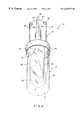
- FIG. 1is an isometric exploded view of a sample collection and storage device according to the invention
- FIG. 2is an isometric assembly view of the sample collection and storage device of FIG. 1;
- FIG. 3is a side elevational view of a sample collection unit of the sample collection and storage device with cap and coring scoop portions in partial cross section to illustrate further details of the invention
- FIG. 4is a rear view of the sample collection unit
- FIG. 5is a front view of the sample collection unit
- FIG. 6is a top plan view of the sample collection unit with the cap portion in partial cross section;
- FIG. 7is a bottom plan view of the sample collection unit
- FIG. 8is an enlarged cross sectional view of a portion of the assembled sample collection and storage device.
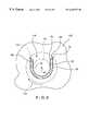
- FIG. 9is an enlarged cross sectional view of the sample collection unit taken along line 9 — 9 of FIG. 7 and showing the unit in operation for obtaining a sample.
- a sample collection and storage device 10comprises a sample collection unit 12 and a storage unit or vial 14 .
- the vial 14is preferably of a substantially cylindrical configuration and includes a continuous side wall 16 that is integrally formed with a bottom wall 18 to form a hollow interior 20 . It should be noted, however, that any conventional configuration of the vial is within the scope of the invention. Outer threads 22 are formed in the continuous side wall 16 at an upper end thereof.
- the vial 14is preferably constructed of a transparent plastic material, such as high-impact polystyrene (HIPS) or other material that can be gamma irradiated for sterilization prior to receiving a sample 24 (shown in phantom line in FIGS. 2 and 9 ). Although a transparent material is preferred for viewing the sample within the vial 14 , it is to be understood that translucent or opaque materials may be alternatively used, depending on the particular requirements of the sample and the requirements associated with sample testing.
- HIPShigh-impact polystyrene
- the sample collection unit 12includes a cap 30 , a coring scoop 32 extending forwardly from the cap, and a handle 34 extending rearwardly from the cap.
- the cap 30is preferably substantially cylindrical and includes a continuous side wall 36 that is integrally formed with a separating wall 38 to form a hollow interior 40 .
- Inner threads 42are formed in the interior area of the continuous side wall 36 which are adapted to mate with the outer threads 22 of the vial 14 when the cap and the vial are engaged.
- an annular sealing ring 44is formed on an inner surface 46 of the separating wall 38 and projects outwardly therefrom.
- the sealing ring 44has an inner surface 48 that is generally parallel with a longitudinal axis 50 (See FIG. 6) of the sample collection unit 12 and an outer surface 52 that slopes generally toward the longitudinal axis.
- annular gasket(not shown) constructed of elastomeric material or the like can be inserted into a space 56 between the wall 36 and the sealing ring 44 to contact and seal against the rim 54 .
- the coring scoop 32includes a pair of spaced side wall portions 60 , 62 that are integrally joined by a connecting wall portion 64 to form an open channel 66 into which the sample is received during sample collection.
- a rear end of the wall portionsare joined to the separating wall 38 of the cap 30 .
- the side wall portions 60 , 62are substantially straight and extend substantially parallel to each other, while the connecting wall portion 64 is curved. In an alternative arrangement, only one side wall is straight and the side wall portions 60 , 62 extend in a non-parallel fashion.
- the center of curvature of the connecting wall portion 64is coincident with the longitudinal axis 50 .
- a front end of the connecting wall portion 64includes an arcuate section 65 that curves generally downwardly.
- the wall portions 60 , 62 and 64are arranged to form a continuous front surface 68 that intersects a continuous outer surface 70 of the coring scoop at an outer cutting edge 72 .
- a continuous inner surface 74 of the coring scoopintersects the continuous front surface 68 at an inner edge 76 .
- the front engaging surface 68is formed with a first straight section 78 that extends from the separating wall 38 substantially parallel to the longitudinal axis 50 , and a second curved section 80 that extends generally downwardly and forwardly from the first section 70 to the connecting wall portion 64 .
- the front surface 68preferably slopes inwardly along its length from the cutting edge 72 to the inner edge 76 .
- the handle 34includes a first I-beam 90 that intersects a second I-beam 92 along the longitudinal axis 50 to form four torque arms 94 that extend radially from the axis 50 at about 90 degree segments and rearwardly from the separating wall 38 of the cap 30 .
- the torque arms 94are equal in radial length and in height.
- a flange 96is formed at the outer upright edge of each torque arm 94 and extends longitudinally along its length.
- Each torque arm 94includes a pair of opposed, flat surfaces 98 , 100 which can be adapted to receive a label (not shown) for identifying the contents of the vial 14 .
- the sample collection unit 12is preferably molded of a plastic material, such as high-impact styrene, that can be gamma irradiated for sterilization and that exhibits good stiffness and strength to resist forces during sampling.
- the coring scoop 32 , cap 30 and handle 34are preferably integrally molded into a unitary structure during the manufacturing process. However, each part may be formed separately and joined together through ultrasonic welding, adhesive, or other known joining techniques. If desired, the entire collection unit 12 or the handle 34 may be colored during manufacture to provide color coding for different types of samples and/or laboratory analyses.
- the sample collection unit 12is inserted into a solid or semi-solid product 110 such as cheese, ice cream, or other product, with the longitudinal axis 50 oriented generally normal to a surface of the product.
- the collection unit 12is rotated about the longitudinal axis 50 . This occurs when the user grasps the handle 34 and presses against the flat surfaces 98 or 100 (depending on the direction of rotation) and flanges 96 of the torque arms 94 with the inner surface of the hand and/or the thumb and fingers.
- the flanges 96assure a tight grip on the handle while rotating and, together with the torque arms, provide a robust grip of the handle regardless of hand size. This is especially important when obtaining samples from relatively hard products are obtained.
- the inner surface 74 of the coring scoopforms a generally cylindrical core sample 24 .
- the cutting edge 72 together with the substantially straight wall portion 62cuts through the product 110 and pushes excess product away from the core sample 24 in a circular path 114 . This motion creates a space 116 between the core sample 24 and the remainder of the product 110 .
- the core sample 24should be separated from the remainder of the product during rotation due to the forces acting on the straight wall portions 60 , 62 from the remaining product. If separation does not occur, the collection unit 12 can be tilted in a remaining space 116 to break the core sample from the product.
- the vial 14is screwed onto the cap to seal the coring scoop and the sample in the vial for storage and transportation as previously described. The position of the cap 30 with respect to the handle 34 and coring scoop 32 minimizes the risk of inadvertent contact between the user's hand and the sample, and thus minimizes the possibility of sample contamination.
Landscapes
- Chemical & Material Sciences (AREA)
- Health & Medical Sciences (AREA)
- General Health & Medical Sciences (AREA)
- Analytical Chemistry (AREA)
- Life Sciences & Earth Sciences (AREA)
- Biochemistry (AREA)
- Physics & Mathematics (AREA)
- General Physics & Mathematics (AREA)
- Immunology (AREA)
- Pathology (AREA)
- Hematology (AREA)
- Clinical Laboratory Science (AREA)
- Chemical Kinetics & Catalysis (AREA)
- Sampling And Sample Adjustment (AREA)
- Closures For Containers (AREA)
Abstract
Description
Claims (19)
Priority Applications (7)
| Application Number | Priority Date | Filing Date | Title |
|---|---|---|---|
| US09/418,471US6440373B1 (en) | 1999-10-15 | 1999-10-15 | Device for collecting and storing samples |
| CA002322108ACA2322108A1 (en) | 1999-10-15 | 2000-10-03 | Device for collecting and storing samples |
| GB0024295AGB2356193B (en) | 1999-10-15 | 2000-10-04 | Device for collecting and storing samples |
| GB0307757AGB2384772B (en) | 1999-10-15 | 2000-10-04 | Device for collecting and storing samples |
| AU62491/00AAU770711B2 (en) | 1999-10-15 | 2000-10-05 | Device for collecting and storing samples |
| DE10050120ADE10050120A1 (en) | 1999-10-15 | 2000-10-11 | Specimen sampling and storing container used in food industries, has cap from which spoon is extended towards inner side of flask |
| JP2000314007AJP2001159590A (en) | 1999-10-15 | 2000-10-13 | Device for sampling and preserving sample |
Applications Claiming Priority (1)
| Application Number | Priority Date | Filing Date | Title |
|---|---|---|---|
| US09/418,471US6440373B1 (en) | 1999-10-15 | 1999-10-15 | Device for collecting and storing samples |
Publications (1)
| Publication Number | Publication Date |
|---|---|
| US6440373B1true US6440373B1 (en) | 2002-08-27 |
Family
ID=23658247
Family Applications (1)
| Application Number | Title | Priority Date | Filing Date |
|---|---|---|---|
| US09/418,471Expired - LifetimeUS6440373B1 (en) | 1999-10-15 | 1999-10-15 | Device for collecting and storing samples |
Country Status (6)
| Country | Link |
|---|---|
| US (1) | US6440373B1 (en) |
| JP (1) | JP2001159590A (en) |
| AU (1) | AU770711B2 (en) |
| CA (1) | CA2322108A1 (en) |
| DE (1) | DE10050120A1 (en) |
| GB (1) | GB2356193B (en) |
Cited By (22)
| Publication number | Priority date | Publication date | Assignee | Title |
|---|---|---|---|---|
| US20030077838A1 (en)* | 2001-10-19 | 2003-04-24 | Monogen, Inc. | Vial system and method for processing liquid-based specimens |
| US20050149187A1 (en)* | 2000-08-28 | 2005-07-07 | Ron Clark | Method and implant for securing ligament replacement into the knee |
| US6915712B1 (en) | 2002-09-06 | 2005-07-12 | Bel-Art Products, Inc. | Detectable sampling arrangement |
| US20060122300A1 (en)* | 2004-12-07 | 2006-06-08 | Zhiyong Xia | Polyester polymer and copolymer compositions containing steel particles |
| US20070287193A1 (en)* | 2004-11-09 | 2007-12-13 | Monogen, Inc. | Vial Assembly, Sampling Apparatus And Method For Processing Liquid-Based Specimens |
| US20080295619A1 (en)* | 2007-06-04 | 2008-12-04 | Swift & Company | Device for obtaining uniform samples of meat and methods of use thereof |
| US7530999B2 (en) | 2000-08-28 | 2009-05-12 | Biomet Sports Medicine, Llc | Method and implant for securing ligament replacement into the knee |
| US20100121219A1 (en)* | 2008-11-07 | 2010-05-13 | Mccabe Edward R B | Mouth Cell Collection Device with Mechanically Rinsible Scoop |
| US20100184126A1 (en)* | 2007-07-24 | 2010-07-22 | University Of Leicester | sampling device |
| US7896917B2 (en) | 2003-10-15 | 2011-03-01 | Biomet Sports Medicine, Llc | Method and apparatus for graft fixation |
| US8002778B1 (en)* | 2004-06-28 | 2011-08-23 | Biomet Sports Medicine, Llc | Crosspin and method for inserting the same during soft ligament repair |
| US8147546B2 (en) | 2007-03-13 | 2012-04-03 | Biomet Sports Medicine, Llc | Method and apparatus for graft fixation |
| US9266633B2 (en) | 2009-09-18 | 2016-02-23 | National Beef Packing Company, Llc | Antimicrobial packaging system |
| US20170100104A1 (en)* | 2011-08-09 | 2017-04-13 | Cook Regentec Llc | Vial useable in tissue extraction procedures |
| CN106840752A (en)* | 2017-02-17 | 2017-06-13 | 南昌富泰力诺检测应用系统有限公司 | A kind of food security examines Special sample and crushes proportional sampling device soon |
| US20180154350A1 (en)* | 2015-03-16 | 2018-06-07 | Dots Technology Corp. | Portable allergen detection system |
| US10183308B2 (en) | 2014-10-14 | 2019-01-22 | Conopco, Inc. | Spraying device |
| US10385560B2 (en) | 2014-10-14 | 2019-08-20 | Conopco, Inc. | Device for spraying an enclosure triggered by inclination of a rotatable lid |
| CN111122224A (en)* | 2020-02-28 | 2020-05-08 | 呼伦贝尔市北方寒冷干旱地区内陆湖泊研究院 | Sampling device and sampling method for lake ice layer dust sedimentation and attached storage contrast ice column |
| WO2020093283A1 (en)* | 2018-11-07 | 2020-05-14 | L'oreal | Device for packaging and dispensing a product having an integrated collecting member |
| CN114878235A (en)* | 2022-06-14 | 2022-08-09 | 长沙海纳光电科技有限公司 | Cement paste sampler |
| CN117309485A (en)* | 2023-10-17 | 2023-12-29 | 江苏权正检验检测有限公司 | Food inspection detects and remains sampling device with medicine |
Families Citing this family (7)
| Publication number | Priority date | Publication date | Assignee | Title |
|---|---|---|---|---|
| DE10144127C1 (en)* | 2001-09-08 | 2003-02-27 | Utz P Merten | Apparatus or holding hold and/or taking a tissue sample, e.g. in a biological biopsy, has an arrangement of hollow cylinders within each other and a plunger, to take and hold the tissue without contamination |
| EP2027922A1 (en)* | 2007-08-02 | 2009-02-25 | Qiagen GmbH | Method and device for securing/stabilising a sample |
| JP6351187B2 (en)* | 2016-11-02 | 2018-07-04 | 国立大学法人北海道大学 | Sample collection tool, sample collection method, sample inspection method |
| CN108225812B (en)* | 2018-01-25 | 2020-01-17 | 四川大学华西医院 | sampling cup |
| AU2021275907A1 (en)* | 2020-05-22 | 2022-12-08 | Schlumberger Technology B.V. | Sidewall coring tool systems and methods |
| CN111693325B (en)* | 2020-06-18 | 2023-05-16 | 北京市农林科学院 | Portable sampling device |
| KR102698742B1 (en)* | 2021-10-26 | 2024-08-26 | 한국해양과학기술원 | Sub-sampler of core sediment and storage device of sub-sampling tip |
Citations (18)
| Publication number | Priority date | Publication date | Assignee | Title |
|---|---|---|---|---|
| US1642985A (en) | 1926-02-19 | 1927-09-20 | Ollie E Beebe | Home-baker's measure |
| US2592192A (en) | 1950-02-17 | 1952-04-08 | Charles H Sanford | Spoon with a base |
| US2718060A (en) | 1954-05-03 | 1955-09-20 | Jr James B Buck | Shortening measure |
| US2770135A (en) | 1954-01-25 | 1956-11-13 | Winifred B Parvin | Measuring and mixing spoon |
| US2799086A (en) | 1954-11-17 | 1957-07-16 | Earl S Tupper | Measuring and scooping cylinder |
| US3001404A (en) | 1959-01-29 | 1961-09-26 | Borden Co | Self-leveling measuring spoon |
| US3013436A (en) | 1958-11-28 | 1961-12-19 | Mead Johnson & Co | Dispensing measure |
| US3049014A (en) | 1958-09-18 | 1962-08-14 | Fiorence L Aue | Kitchen utensil |
| USD253869S (en) | 1977-09-14 | 1980-01-08 | O.M. Scott & Sons Company | Adjustable fertilizer applicator for house plants |
| US4735905A (en) | 1986-08-15 | 1988-04-05 | V-Tech, Inc. | Specimen-gathering apparatus and method |
| US4859610A (en)* | 1985-06-05 | 1989-08-22 | Synbiotics Corporation | Immunoassay incubation device |
| CH672873A5 (en)* | 1985-07-11 | 1990-01-15 | Barbara Streuli C O Frau R Str | Plastics container for dog dung - has lid with handle and scoop forming air- and watertight joint |
| USD328867S (en) | 1990-03-13 | 1992-08-25 | Robbins Industries, Inc. | Spice spoon |
| US5149506A (en) | 1991-08-09 | 1992-09-22 | Sage Products, Inc. | Stool collection and transport device |
| US5347865A (en) | 1992-11-05 | 1994-09-20 | Amway Corporation | Measuring scoop with molded reusable fit clip |
| US5431884A (en) | 1994-02-22 | 1995-07-11 | Sage Products, Inc. | Specimen transporting and processing system |
| US5440942A (en) | 1994-02-02 | 1995-08-15 | Hubbard; Stephen H. | Biological sample collecting and holding device |
| US5624554A (en) | 1993-11-22 | 1997-04-29 | Biomedical Polymers, Inc. | Collection and transfer device |
- 1999
- 1999-10-15USUS09/418,471patent/US6440373B1/ennot_activeExpired - Lifetime
- 2000
- 2000-10-03CACA002322108Apatent/CA2322108A1/ennot_activeAbandoned
- 2000-10-04GBGB0024295Apatent/GB2356193B/ennot_activeExpired - Fee Related
- 2000-10-05AUAU62491/00Apatent/AU770711B2/ennot_activeCeased
- 2000-10-11DEDE10050120Apatent/DE10050120A1/ennot_activeWithdrawn
- 2000-10-13JPJP2000314007Apatent/JP2001159590A/enactivePending
Patent Citations (18)
| Publication number | Priority date | Publication date | Assignee | Title |
|---|---|---|---|---|
| US1642985A (en) | 1926-02-19 | 1927-09-20 | Ollie E Beebe | Home-baker's measure |
| US2592192A (en) | 1950-02-17 | 1952-04-08 | Charles H Sanford | Spoon with a base |
| US2770135A (en) | 1954-01-25 | 1956-11-13 | Winifred B Parvin | Measuring and mixing spoon |
| US2718060A (en) | 1954-05-03 | 1955-09-20 | Jr James B Buck | Shortening measure |
| US2799086A (en) | 1954-11-17 | 1957-07-16 | Earl S Tupper | Measuring and scooping cylinder |
| US3049014A (en) | 1958-09-18 | 1962-08-14 | Fiorence L Aue | Kitchen utensil |
| US3013436A (en) | 1958-11-28 | 1961-12-19 | Mead Johnson & Co | Dispensing measure |
| US3001404A (en) | 1959-01-29 | 1961-09-26 | Borden Co | Self-leveling measuring spoon |
| USD253869S (en) | 1977-09-14 | 1980-01-08 | O.M. Scott & Sons Company | Adjustable fertilizer applicator for house plants |
| US4859610A (en)* | 1985-06-05 | 1989-08-22 | Synbiotics Corporation | Immunoassay incubation device |
| CH672873A5 (en)* | 1985-07-11 | 1990-01-15 | Barbara Streuli C O Frau R Str | Plastics container for dog dung - has lid with handle and scoop forming air- and watertight joint |
| US4735905A (en) | 1986-08-15 | 1988-04-05 | V-Tech, Inc. | Specimen-gathering apparatus and method |
| USD328867S (en) | 1990-03-13 | 1992-08-25 | Robbins Industries, Inc. | Spice spoon |
| US5149506A (en) | 1991-08-09 | 1992-09-22 | Sage Products, Inc. | Stool collection and transport device |
| US5347865A (en) | 1992-11-05 | 1994-09-20 | Amway Corporation | Measuring scoop with molded reusable fit clip |
| US5624554A (en) | 1993-11-22 | 1997-04-29 | Biomedical Polymers, Inc. | Collection and transfer device |
| US5440942A (en) | 1994-02-02 | 1995-08-15 | Hubbard; Stephen H. | Biological sample collecting and holding device |
| US5431884A (en) | 1994-02-22 | 1995-07-11 | Sage Products, Inc. | Specimen transporting and processing system |
Non-Patent Citations (1)
| Title |
|---|
| Bel-Art Products, Inc. Catalog 198 (pp. 381-413). |
Cited By (35)
| Publication number | Priority date | Publication date | Assignee | Title |
|---|---|---|---|---|
| US20050149187A1 (en)* | 2000-08-28 | 2005-07-07 | Ron Clark | Method and implant for securing ligament replacement into the knee |
| US7530999B2 (en) | 2000-08-28 | 2009-05-12 | Biomet Sports Medicine, Llc | Method and implant for securing ligament replacement into the knee |
| US7837718B2 (en) | 2000-08-28 | 2010-11-23 | Biomet Sports Medicine, Llc | Method and implant for securing ligament replacement into the knee |
| US7807476B2 (en) | 2001-10-19 | 2010-10-05 | Hologic, Inc. | Vial system and method for processing liquid-based specimens |
| US20030077838A1 (en)* | 2001-10-19 | 2003-04-24 | Monogen, Inc. | Vial system and method for processing liquid-based specimens |
| US7771662B2 (en)* | 2001-10-19 | 2010-08-10 | Hologic, Inc | Vial system and method for processing liquid-based specimens |
| US6915712B1 (en) | 2002-09-06 | 2005-07-12 | Bel-Art Products, Inc. | Detectable sampling arrangement |
| US7896917B2 (en) | 2003-10-15 | 2011-03-01 | Biomet Sports Medicine, Llc | Method and apparatus for graft fixation |
| US8784489B2 (en) | 2003-10-15 | 2014-07-22 | Biomet Sports Medicine, Llc | Method and apparatus for graft fixation |
| US8002778B1 (en)* | 2004-06-28 | 2011-08-23 | Biomet Sports Medicine, Llc | Crosspin and method for inserting the same during soft ligament repair |
| US20070287193A1 (en)* | 2004-11-09 | 2007-12-13 | Monogen, Inc. | Vial Assembly, Sampling Apparatus And Method For Processing Liquid-Based Specimens |
| US20060122300A1 (en)* | 2004-12-07 | 2006-06-08 | Zhiyong Xia | Polyester polymer and copolymer compositions containing steel particles |
| US8900301B2 (en) | 2007-03-13 | 2014-12-02 | Biomet Sports Medicine, Llc | Method and apparatus for graft fixation |
| US8147546B2 (en) | 2007-03-13 | 2012-04-03 | Biomet Sports Medicine, Llc | Method and apparatus for graft fixation |
| US7866223B2 (en) | 2007-06-04 | 2011-01-11 | Swift & Company | Method of obtaining samples of meat to assay for microbial contamination |
| US20080295619A1 (en)* | 2007-06-04 | 2008-12-04 | Swift & Company | Device for obtaining uniform samples of meat and methods of use thereof |
| US8652802B2 (en)* | 2007-07-24 | 2014-02-18 | University Of Leicester | Sampling device |
| US20100184126A1 (en)* | 2007-07-24 | 2010-07-22 | University Of Leicester | sampling device |
| US20100121219A1 (en)* | 2008-11-07 | 2010-05-13 | Mccabe Edward R B | Mouth Cell Collection Device with Mechanically Rinsible Scoop |
| US9266633B2 (en) | 2009-09-18 | 2016-02-23 | National Beef Packing Company, Llc | Antimicrobial packaging system |
| US9296504B2 (en) | 2009-09-18 | 2016-03-29 | National Beef Packing Company, Llc | Antimicrobial packaging system |
| US20170100104A1 (en)* | 2011-08-09 | 2017-04-13 | Cook Regentec Llc | Vial useable in tissue extraction procedures |
| US10653397B2 (en)* | 2011-08-09 | 2020-05-19 | Gallant Pet, Inc. | Vial useable in tissue extraction procedures |
| US10385560B2 (en) | 2014-10-14 | 2019-08-20 | Conopco, Inc. | Device for spraying an enclosure triggered by inclination of a rotatable lid |
| US10183308B2 (en) | 2014-10-14 | 2019-01-22 | Conopco, Inc. | Spraying device |
| US20180154350A1 (en)* | 2015-03-16 | 2018-06-07 | Dots Technology Corp. | Portable allergen detection system |
| US10835897B2 (en)* | 2015-03-16 | 2020-11-17 | Dots Technology Corp. | Portable allergen detection system |
| CN106840752A (en)* | 2017-02-17 | 2017-06-13 | 南昌富泰力诺检测应用系统有限公司 | A kind of food security examines Special sample and crushes proportional sampling device soon |
| CN106840752B (en)* | 2017-02-17 | 2023-05-09 | 南昌富泰力诺检测应用系统有限公司 | Special sample smashing quantitative sampler for food safety quick detection |
| WO2020093283A1 (en)* | 2018-11-07 | 2020-05-14 | L'oreal | Device for packaging and dispensing a product having an integrated collecting member |
| RU2771055C1 (en)* | 2018-11-07 | 2022-04-25 | Л'Ореаль | Device for packaging and feeding the product with a built-in collecting element |
| CN111122224A (en)* | 2020-02-28 | 2020-05-08 | 呼伦贝尔市北方寒冷干旱地区内陆湖泊研究院 | Sampling device and sampling method for lake ice layer dust sedimentation and attached storage contrast ice column |
| CN114878235A (en)* | 2022-06-14 | 2022-08-09 | 长沙海纳光电科技有限公司 | Cement paste sampler |
| CN114878235B (en)* | 2022-06-14 | 2023-08-22 | 长沙海纳光电科技有限公司 | Cement paste sampler |
| CN117309485A (en)* | 2023-10-17 | 2023-12-29 | 江苏权正检验检测有限公司 | Food inspection detects and remains sampling device with medicine |
Also Published As
| Publication number | Publication date |
|---|---|
| JP2001159590A (en) | 2001-06-12 |
| GB0024295D0 (en) | 2000-11-15 |
| CA2322108A1 (en) | 2001-04-15 |
| AU770711B2 (en) | 2004-02-26 |
| AU6249100A (en) | 2001-04-26 |
| GB2356193A (en) | 2001-05-16 |
| GB2356193B (en) | 2003-07-09 |
| DE10050120A1 (en) | 2001-04-19 |
Similar Documents
| Publication | Publication Date | Title |
|---|---|---|
| US6440373B1 (en) | Device for collecting and storing samples | |
| US5458854A (en) | Collection assembly | |
| EP0676171B1 (en) | Collection assembly | |
| US10894256B2 (en) | Ergonomic stool specimen container and enclosing holder systems, methods, and kits | |
| US12005438B2 (en) | Sample collection apparatus and uses thereof | |
| US20200369445A1 (en) | Gaskets and beverage container systems and kits comprising gaskets | |
| CA2067695C (en) | Blood microcollection tube assembly | |
| US8617487B2 (en) | Saliva sample collection systems | |
| AU748070B2 (en) | Collection container assembly | |
| US5458113A (en) | Collection assembly | |
| US20120211459A1 (en) | Package with foil seals and penetrating means | |
| US3860148A (en) | Liquid container | |
| US6293435B1 (en) | Liquid sample collection and transport system | |
| KR102111659B1 (en) | specimen container | |
| CA2245031C (en) | Collection container assembly | |
| JP2001503718A (en) | Universal plug | |
| GB2384772A (en) | Device for collecting and storing samples | |
| US4768669A (en) | Flexible sealing top | |
| AU8317598A (en) | Collection container assembly | |
| SE516248C2 (en) | Process for mixing a liquid in a largely liquid-filled container which has a top partially closed opening and containers for carrying out the process | |
| JP2589216Y2 (en) | Inspection container | |
| GB2287234A (en) | Sampling container with removable handle | |
| TR2021012980U5 (en) | CONSTRUCTION OF EASY-TO-USE BODY FOR BOXES WITH EASY OPENING LIDS | |
| AU1635899A (en) | Dispensing implement | |
| JPH0685296U (en) | Container mouth seal lid opener |
Legal Events
| Date | Code | Title | Description |
|---|---|---|---|
| AS | Assignment | Owner name:BEL-ART PRODUCTS, INC., NEW JERSEY Free format text:ASSIGNMENT OF ASSIGNORS INTEREST;ASSIGNORS:GOMES, FRANCIS;FOLLMAN, MARK;LANDSBERGER, DAVID;REEL/FRAME:010494/0863 Effective date:19991118 | |
| STCF | Information on status: patent grant | Free format text:PATENTED CASE | |
| REMI | Maintenance fee reminder mailed | ||
| FPAY | Fee payment | Year of fee payment:4 | |
| SULP | Surcharge for late payment | ||
| FPAY | Fee payment | Year of fee payment:8 | |
| FPAY | Fee payment | Year of fee payment:12 | |
| AS | Assignment | Owner name:ANTARES CAPITAL LP, AS AGENT, ILLINOIS Free format text:SECURITY INTEREST;ASSIGNORS:SP INDUSTRIES, INC.;BEL-ART PRODUCTS;APPLIED COATINGS, INC.;AND OTHERS;REEL/FRAME:037237/0647 Effective date:20151208 | |
| AS | Assignment | Owner name:MADDAK, INC., NEW JERSEY Free format text:RELEASE BY SECURED PARTY;ASSIGNOR:BANK OF MONTREAL;REEL/FRAME:037331/0559 Effective date:20151208 Owner name:GENEVAC, INC., NEW YORK Free format text:RELEASE BY SECURED PARTY;ASSIGNOR:BANK OF MONTREAL;REEL/FRAME:037331/0559 Effective date:20151208 Owner name:SP INDUSTRIES, INC., PENNSYLVANIA Free format text:RELEASE BY SECURED PARTY;ASSIGNOR:BANK OF MONTREAL;REEL/FRAME:037331/0559 Effective date:20151208 Owner name:BEL-ART PRODUCTS, NEW JERSEY Free format text:RELEASE BY SECURED PARTY;ASSIGNOR:BANK OF MONTREAL;REEL/FRAME:037331/0559 Effective date:20151208 |