US6439523B1 - Universal mounting system for a fiber optic management center - Google Patents
Universal mounting system for a fiber optic management centerDownload PDFInfo
- Publication number
- US6439523B1 US6439523B1US09/587,065US58706500AUS6439523B1US 6439523 B1US6439523 B1US 6439523B1US 58706500 AUS58706500 AUS 58706500AUS 6439523 B1US6439523 B1US 6439523B1
- Authority
- US
- United States
- Prior art keywords
- enclosure
- rack
- pattern
- orientation
- side section
- Prior art date
- Legal status (The legal status is an assumption and is not a legal conclusion. Google has not performed a legal analysis and makes no representation as to the accuracy of the status listed.)
- Expired - Fee Related
Links
- 239000000835fiberSubstances0.000titleabstractdescription15
- 238000012986modificationMethods0.000description2
- 230000004048modificationEffects0.000description2
- 238000000926separation methodMethods0.000description2
- 230000004075alterationEffects0.000description1
- 238000000034methodMethods0.000description1
- 230000008520organizationEffects0.000description1
- 230000008569processEffects0.000description1
Images

Classifications
- G—PHYSICS
- G02—OPTICS
- G02B—OPTICAL ELEMENTS, SYSTEMS OR APPARATUS
- G02B6/00—Light guides; Structural details of arrangements comprising light guides and other optical elements, e.g. couplings
- G02B6/44—Mechanical structures for providing tensile strength and external protection for fibres, e.g. optical transmission cables
- G02B6/4439—Auxiliary devices
- G02B6/444—Systems or boxes with surplus lengths
- G02B6/4452—Distribution frames
- G02B6/44526—Panels or rackmounts covering a whole width of the frame or rack
Definitions
- the present inventionrelates generally to a fiber optic communication center and more particularly to a universal system for mounting fiber optic interconnection enclosures to a fiber optic rack.
- a fiber optic communication centerrepresents a “node” where fiber optic networks are connected.
- individual fiber optic cablesare interconnected within an enclosure, such as splice, connector and modular enclosure.
- the communication centeris defined by a series of enclosures mounted on a rack, thereby facilitating organization of the various fiber optic networks.
- the industryhas multiple standards for the enclosure-carrying racks.
- WECOWestern Electric Company
- EIAElectronics Industries Alliance/Telecommunications Industry Association
- the mounting apertures of the WECO rackare equally spaced at 1 inch increments (hereinafter referred to as the “WECO Pattern”).
- WECO Patternthe mounting apertures are alternately spaced at 1.25 inches and 0.5 inch
- the horizontal spacing, or gap, between the vertical racksvaries between two unofficial standards.
- a “public network,” such as sold by WECOthe racks are separated by 23 inches, providing a useable gap of 21.5 inches.
- a “premises network,” such as sold by EIAthe separation is 19 inches with a useable gap of 17.5 inches.
- the present inventionis a universal mounting system for use ith both the WECO and EIA racks.
- the present inventionincludes a bracket having a series of mounting apertures. Regardless of the orientation of the bracket with respect to the rack, the mounting apertures at least partially match the WECO Pattern and EIA Pattern, thereby facilitating attachment.
- the term “at least partially match” and obvious modifications thereofmean alignment of at least two non-adjacent mounting apertures on the bracket with two mounting apertures of the WECO Pattern and EIA Pattern.
- Another objectis an enclosure-mounting system for use, without alteration, with WECO and EIA racks.
- Still another objectis a universal enclosure-mounting system for use with WECO and EIA racks in either network configuration, i.e., public or premises.
- Yet another object of the present inventionis a universal enclosure-mounting system wherein the enclosure is supported by a rack bracket to facilitate the attachment process. It is also an object to provide a universal enclosure-mounting system wherein the spacing between adjacent enclosures on the rack is minimized.
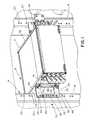
- FIG. 1is a partial perspective view of a fiber optic communication center, illustrating a preferred embodiment of the present invention in a rack having the EIA Pattern;
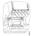
- FIG. 2is an enlarged partial perspective view
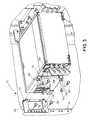
- FIG. 3is an exploded perspective view of the preferred embodiment shown in FIG. 1;
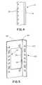
- FIG. 4is a front view of a rack with the WECO Pattern.
- FIG. 5is an enlarged perspective view of a second preferred embodiment of the present invention.
- FIGS. 1-3A first preferred embodiment of the present invention is shown in FIGS. 1-3 as a system, generally designated 10 , for attaching fiber optic enclosure 12 to a rack, generally designated 14 .
- the rack 14includes left and right vertically secured frames 16 , 18 .
- the rack 14as shown in FIGS. 1-3, is an EIA rack, having the EIA Pattern of holes 20 .
- the holes 20are alternately spaced at 1.25 inches and 0.5 inch, center-to-center.
- the system 10further accommodates the WECO Pattern of holes 22 , as shown in FIG. 4, where the spacing is equal and on 1 inch centers.
- the holes 20 , 22are threaded to receive a No. 12 screw with 24 threads per inch.
- the system 10includes a pair of substantially identical rack brackets 24 , secured in horizontal alignment to the left and right frames 16 , 18 by screws 26 .
- the first and second, or left and right, rack brackets 24are secured on the frames 16 , 18 in a reversed orientation, i.e., the first bracket 24 is rotated 180° with respect to the second.
- the bracket 24includes a substantially planar, substantially rectangular rack-mounting plate 28 and a pair of support tabs 30 , 32 , respectively.
- the width of the plate 28is about 3 inches.
- the plate 28has a first section 34 , second section 36 , first-side or rack-side section 38 , and second-side or enclosure-side section 40 , defining a central, substantially rectangular opening 42 .
- This opening 42provides fiber optic cable access to the rear of the system 10 .
- the first and second support tabs 30 , 32extend from an outer edge 44 of the enclosure-side section 40 , substantially perpendicular to the rack-mounting plate 28 . As shown, the support tabs 30 , 32 are equally displaced from the outer edges 46 , 48 of the first and second sections 34 , 36 , respectively.
- the rack-side section 38defines a series, generally designated 50 , of rack apertures 52 , 54 , 56 , 58 , 60 , 62 , 64 , 66 , 68 .
- the central aperture 60defines the center of the series 50 , and the apertures 62 , 64 , 66 , 68 are displaced therefrom at center-to-center intervals of 0.5, 1.125, 1.375 and 2 inches.
- the other apertures 52 , 54 , 56 , 58are similarly positioned from the center aperture 60 .
- the series 50allows use of the bracket 24 , in both orientations, with the WECO Pattern and EIA Pattern. That is, the series 50 results in at least partial matching of non-adjacent rack apertures 52 , 54 , 56 , 58 , 60 , 62 , 64 , 66 , 68 with at least two apertures of the WECO Pattern and EIA Pattern in both the first and second, or left and right, orientations of the bracket 24 with respect to the rack 14 .
- Use of non-adjacent apertures within the series 50enhances the structural integrity of the system 10 .
- the series 50provides the option of avoiding use of both hourglass-shaped openings, as defined by the apertures 54 , 56 and 64 , 66 , in any given application. Loosening due to the vibration is thereby substantially avoided.
- the enclosure-side section 40 of the rack bracket 24defines first and second enclosure-mounting apertures 70 , 72 .
- the apertures 70 , 72also threaded to receive a No. 12 screw, have a predetermined opposed relationship, i.e., the apertures 70 , 72 are at opposite ends of the enclosure-side section 40 , with a center-to-center separation of 4 inches.
- the support tabs 30 , 32are inwardly displaced from the enclosure-mounting apertures 70 , 72 .
- the system 10further includes a pair of substantially identical enclosure brackets 74 .
- the enclosure brackets 74are secured to opposite sides 76 , 78 of the enclosure 12 , in first and second, or left and right, reversed enclosure orientations, similar to the rack brackets 24 .
- Each of the enclosure brackets 74includes a substantially planar enclosure attaching plate 80 and first and second flanges 82 , 84 , extending substantially perpendicular therefrom.
- the width of the plate 80is about 0.5 inch.
- the plate 80defines two enclosure-attaching apertures 86 , 88 , such that the enclosure brackets are affixed by screws 90 .
- the first and second flanges 82 , 84are slotted to define third and fourth enclosure-mounting apertures 92 , 94 , respectively.
- the apertures 92 , 94have the same predetermined opposed relationship as the first and second enclosure-mounting apertures 70 , 72 of the rack bracket 24 , further facilitating attachment of the enclosure 12 to the rack 14 .
- first and second support tabs 30 , 32engage the first and second flanges 82 , 84 as the enclosure 12 is manually maneuvered onto the rack 14 .
- This engagementguides the third and fourth enclosure-mounting apertures 92 , 94 into alignment with the first and second enclosure-mounting apertures 70 , 72 .
- the tabs 30 , 32interpose the flanges 82 , 84 , thereby supporting the enclosure 12 during attachment to the rack 14 .
- a second preferred embodiment of the present inventionis shown in FIG. 5 as a single universal bracket 96 for direct attachment to both the enclosure 12 and rack 14 .
- the bracket 96is substantially L-shaped, having a plate portion 98 and a flange portion 100 .
- the plate portion 98is substantially identical to the rack-mounting plate 28 of the first preferred embodiment, described above, including the aperture series 50 .
- the flange portion 100is substantially planar and extends substantially perpendicular from the outer edge 44 of the enclosure-side section 40 thereof.
- the flange portion 100defines an aperture series, generally designated 102 .
- the series 102is substantially identical to, and horizontally aligned with, the series 50 of the plate portion 98 .
- the bracket 96can be mounted to the left and right frames 16 , 18 of the rack 14 , regardless of hole pattern. Furthermore, the bracket 96 can be used with both the 19 inch and 23 inch frame spacing. With 19 inch spacing, the flange portion 100 is affixed to the frames 16 , 18 ; with 23 inch spacing, the plate portion 98 is affixed to the frames 16 , 18 .
- Both embodimentsare designed for use with enclosures 12 having a height of about 5.25 inches.
- the enclosures 12can be mounted on the rack 14 with virtually no interposing vertical spacing or gap. As such, the number of enclosures 12 per rack 14 is maximized.
Landscapes
- Physics & Mathematics (AREA)
- General Physics & Mathematics (AREA)
- Optics & Photonics (AREA)
- Structure Of Telephone Exchanges (AREA)
Abstract
Description
This disclosure is related to the following U.S. patent applications filed on the same date as this application, each of which is owned by the assignee of this application, and the entirety of each of which is hereby incorporated herein by reference:
U.S. Patent Application entitled “Improved Cable Management System,” naming Jack E. Caveney and Dale A. Block as inventors.
U.S. Patent Application entitled “Slack Cable Management System,” naming Jack E. Caveney as an inventor.
U.S. Patent Application entitled “Improved Enclosure for Use in Fiber Optic Management Systems,” naming Michael T. Vavrik and Philip B. Chandler, Jr. as inventors.
U.S. Patent Application entitled “Modular Latch and Guide Rail Arrangement for Use in Fiber Optic Cable Management Systems,” naming Samuel M. Marrs, Robert R. Brown, and John J. Bulanda as inventors.
U.S. Patent Application entitled “Vertical Cable Management System,” naming Samuel M. Marrs, Michael T. Vavrik, and Jeff Paliga as inventors.
The present invention relates generally to a fiber optic communication center and more particularly to a universal system for mounting fiber optic interconnection enclosures to a fiber optic rack.
A fiber optic communication center represents a “node” where fiber optic networks are connected. Typically, individual fiber optic cables are interconnected within an enclosure, such as splice, connector and modular enclosure. The communication center is defined by a series of enclosures mounted on a rack, thereby facilitating organization of the various fiber optic networks.
Unfortunately, the industry has multiple standards for the enclosure-carrying racks. For example, there are presently two standards for the mounting hole pattern on the vertically extending rack. One was specified by the Western Electric Company (“WECO”); the other is specified by the Electronics Industries Alliance/Telecommunications Industry Association (“EIA”). More particularly, the mounting apertures of the WECO rack are equally spaced at 1 inch increments (hereinafter referred to as the “WECO Pattern”). In the EIA rack, the mounting apertures are alternately spaced at 1.25 inches and 0.5 inch (hereinafter referred to as the “EIA Pattern”).
Additionally the horizontal spacing, or gap, between the vertical racks varies between two unofficial standards. In a “public network,” such as sold by WECO, the racks are separated by 23 inches, providing a useable gap of 21.5 inches. In a “premises network,” such as sold by EIA, the separation is 19 inches with a useable gap of 17.5 inches.
In a principal aspect, the present invention is a universal mounting system for use ith both the WECO and EIA racks. The present invention includes a bracket having a series of mounting apertures. Regardless of the orientation of the bracket with respect to the rack, the mounting apertures at least partially match the WECO Pattern and EIA Pattern, thereby facilitating attachment. As used herein, the term “at least partially match” and obvious modifications thereof mean alignment of at least two non-adjacent mounting apertures on the bracket with two mounting apertures of the WECO Pattern and EIA Pattern.
It is thus an object of the present invention to provide an improved mounting system for attaching an enclosure to a fiber optic rack. Another object is an enclosure-mounting system for use, without alteration, with WECO and EIA racks. Still another object is a universal enclosure-mounting system for use with WECO and EIA racks in either network configuration, i.e., public or premises. Yet another object of the present invention is a universal enclosure-mounting system wherein the enclosure is supported by a rack bracket to facilitate the attachment process. It is also an object to provide a universal enclosure-mounting system wherein the spacing between adjacent enclosures on the rack is minimized.
These and other features, objects and advantages of the present invention are set forth or apparent in the following detailed description.
Various preferred embodiments of the present invention are described herein with reference to the drawing herein:
FIG. 1 is a partial perspective view of a fiber optic communication center, illustrating a preferred embodiment of the present invention in a rack having the EIA Pattern;
FIG. 2 is an enlarged partial perspective view;
FIG. 3 is an exploded perspective view of the preferred embodiment shown in FIG. 1;
FIG. 4 is a front view of a rack with the WECO Pattern; and
FIG. 5 is an enlarged perspective view of a second preferred embodiment of the present invention.
A first preferred embodiment of the present invention is shown in FIGS. 1-3 as a system, generally designated10, for attaching fiberoptic enclosure 12 to a rack, generally designated14. As is well known in the art, therack 14 includes left and right vertically securedframes rack 14, as shown in FIGS. 1-3, is an EIA rack, having the EIA Pattern ofholes 20. As shown, theholes 20 are alternately spaced at 1.25 inches and 0.5 inch, center-to-center. Thesystem 10 further accommodates the WECO Pattern ofholes 22, as shown in FIG. 4, where the spacing is equal and on 1 inch centers. Theholes
Thesystem 10 includes a pair of substantiallyidentical rack brackets 24, secured in horizontal alignment to the left andright frames screws 26. The first and second, or left and right,rack brackets 24 are secured on theframes first bracket 24 is rotated 180° with respect to the second.
Thebracket 24 includes a substantially planar, substantially rectangular rack-mounting plate 28 and a pair ofsupport tabs plate 28 is about 3 inches. Theplate 28 has afirst section 34,second section 36, first-side or rack-side section 38, and second-side or enclosure-side section 40, defining a central, substantiallyrectangular opening 42. Thisopening 42 provides fiber optic cable access to the rear of thesystem 10.
The first andsecond support tabs outer edge 44 of the enclosure-side section 40, substantially perpendicular to the rack-mounting plate 28. As shown, thesupport tabs outer edges second sections
The rack-side section 38 defines a series, generally designated50, ofrack apertures central aperture 60 defines the center of theseries 50, and theapertures other apertures center aperture 60. Theapertures apertures bracket 24 on therack 14.
Theseries 50 allows use of thebracket 24, in both orientations, with the WECO Pattern and EIA Pattern. That is, theseries 50 results in at least partial matching ofnon-adjacent rack apertures bracket 24 with respect to therack 14. Use of non-adjacent apertures within theseries 50 enhances the structural integrity of thesystem 10. Additionally, theseries 50 provides the option of avoiding use of both hourglass-shaped openings, as defined by theapertures
The enclosure-side section 40 of therack bracket 24 defines first and second enclosure-mounting apertures apertures apertures side section 40, with a center-to-center separation of 4 inches. Thesupport tabs apertures
Thesystem 10 further includes a pair of substantiallyidentical enclosure brackets 74. Theenclosure brackets 74 are secured toopposite sides enclosure 12, in first and second, or left and right, reversed enclosure orientations, similar to therack brackets 24.
Each of theenclosure brackets 74 includes a substantially planarenclosure attaching plate 80 and first andsecond flanges plate 80 is about 0.5 inch. Theplate 80 defines two enclosure-attachingapertures screws 90.
The first andsecond flanges apertures apertures apertures rack bracket 24, further facilitating attachment of theenclosure 12 to therack 14.
Additionally, the first andsecond support tabs second flanges enclosure 12 is manually maneuvered onto therack 14. This engagement guides the third and fourth enclosure-mountingapertures apertures tabs flanges enclosure 12 during attachment to therack 14.
A second preferred embodiment of the present invention is shown in FIG. 5 as a singleuniversal bracket 96 for direct attachment to both theenclosure 12 andrack 14. Thebracket 96 is substantially L-shaped, having aplate portion 98 and aflange portion 100. Theplate portion 98 is substantially identical to the rack-mountingplate 28 of the first preferred embodiment, described above, including theaperture series 50. Theflange portion 100 is substantially planar and extends substantially perpendicular from theouter edge 44 of the enclosure-side section 40 thereof.
In this preferred embodiment, theflange portion 100 defines an aperture series, generally designated102. Theseries 102 is substantially identical to, and horizontally aligned with, theseries 50 of theplate portion 98.
As such, thebracket 96 can be mounted to the left andright frames rack 14, regardless of hole pattern. Furthermore, thebracket 96 can be used with both the 19 inch and 23 inch frame spacing. With 19 inch spacing, theflange portion 100 is affixed to theframes plate portion 98 is affixed to theframes
Both embodiments are designed for use withenclosures 12 having a height of about 5.25 inches. Given the WECO and EIA Patterns, theenclosures 12 can be mounted on therack 14 with virtually no interposing vertical spacing or gap. As such, the number ofenclosures 12 perrack 14 is maximized.
Preferred embodiments of the present invention have been described herein. It is to be understood that modifications and changes can be made without departing from the true scope and spirit of the present invention, as defined by the following claims which are to be interpreted in view of the foregoing.
Claims (8)
1. A system for attaching an enclosure to a rack, having a WECO Pattern or an EIA Pattern, comprising, in combination:
first and second rack brackets secured to the rack in a first rack orientation and second rack orientation, respectively, said first rack orientation being reversed from said second rack orientation;
each of said first and second rack brackets including a rack-mounting plate, having a rack-side section and an enclosure-side section, and first and second support tabs extending from said enclosure-side section substantially perpendicular to said rack-mounting plate;
said rack-side section defining a series of rack apertures at least partially matching the WECO Pattern and the EIA Pattern in said first rack orientation and said second rack orientation;
said enclosure-side section defining first and second enclosure-mounting apertures having a predetermined opposed relationship; and
first and second enclosure brackets secured to the enclosure in a first enclosure orientation and a second enclosure orientation, said first enclosure orientation being reversed from send second enclosure orientation;
each of said first and second enclosure brackets including an enclosure-mounting plate and first and second flanges extending substantially perpendicular from said enclosure-mounting plate;
said first and second flanges defining third and fourth enclosure-mounting apertures having said predetermined opposed relationship;
said first and second support tabs engaging said first and second flanges to guide said third and fourth enclosure-mounting apertures into alignment with said first and second enclosure-mounting apertures and support the enclosure with respect to the rack, thereby facilitating attachment of the enclosure to the rack.
2. A system as claimed inclaim 1 wherein said first and second support tabs interposed said first and second flanges.
3. A system as claimed inclaim 2 wherein said first and second flanges are slotted to provide said third and fourth enclosure-mounting apertures.
4. A bracket assembly for attaching an enclosure to a rack, having a WECO Pattern or an EIA Pattern, comprising, in combination:
a rack bracket securable to the rack in first and second rack orientations, said rack bracket including a rack-mounting plate, having a rack-side section and an enclosure-side section, and first and second support tabs extending from said enclosure-side section substantially perpendicular to said rack-mounting plate;
said rack-side section defining a series of rack apertures at least partially matching the WECO Pattern and the EIA Pattern in said first rack orientation and said second rack orientation;
said enclosure-side section defining first and second enclosure-mounting apertures having a predetermined opposed relationship; and
an enclosure bracket securable to the enclosure in first and second enclosure orientations, said enclosure bracket including an enclosure-mounting plate and first and second flanges extending substantially perpendicular from said enclosure-mounting plate;
said first and second flanges defining third and fourth enclosure-mounting apertures having said predetermined opposed relationship;
said first and second support tabs engaging said first and second flanges to guide said third and fourth enclosure-mounting apertures into alignment with said first and second enclosure-mounting apertures and support the enclosure with respect to the rack, thereby facilitating attachment of the enclosure to the rack.
5. A bracket assembly as claimed inclaim 4 wherein said first and second support tabs interposed said first and second flanges.
6. A system as claimed inclaim 5 wherein said first and second flanges are slotted to provide said third and fourth enclosure-mounting apertures.
7. A bracket for attaching an enclosure to a rack, having a WECO Pattern or an EIA Pattern, said bracket having first and second mounting orientations, comprising:
a plate portion including a first-side section and a second-side section, said first-side section defining a plate series of apertures at least partially matching the WECO Pattern and the EIA Pattern in said first orientation and said second orientation.
8. A bracket for attaching an enclosure to a rack, having a WECO Pattern or an EIA Pattern, said bracket having first and second mounting orientations, comprising, in combination:
a plate portion including a first-side section and a second-side section, said first-side section defining a plate series of apertures at least partially matching the WECO Pattern and the EIA Pattern in said first orientation and said second orientation; and
a flange portion extending substantially perpendicular from said second-side section, said flange portion defining a flange series of apertures at least partially matching the WECO Pattern and the EIA Pattern in said first orientation and said second orientation, said flange series substantially aligning with said plate series.
Priority Applications (1)
| Application Number | Priority Date | Filing Date | Title |
|---|---|---|---|
| US09/587,065US6439523B1 (en) | 2000-06-02 | 2000-06-02 | Universal mounting system for a fiber optic management center |
Applications Claiming Priority (1)
| Application Number | Priority Date | Filing Date | Title |
|---|---|---|---|
| US09/587,065US6439523B1 (en) | 2000-06-02 | 2000-06-02 | Universal mounting system for a fiber optic management center |
Publications (1)
| Publication Number | Publication Date |
|---|---|
| US6439523B1true US6439523B1 (en) | 2002-08-27 |
Family
ID=24348196
Family Applications (1)
| Application Number | Title | Priority Date | Filing Date |
|---|---|---|---|
| US09/587,065Expired - Fee RelatedUS6439523B1 (en) | 2000-06-02 | 2000-06-02 | Universal mounting system for a fiber optic management center |
Country Status (1)
| Country | Link |
|---|---|
| US (1) | US6439523B1 (en) |
Cited By (49)
| Publication number | Priority date | Publication date | Assignee | Title |
|---|---|---|---|---|
| US20030079901A1 (en)* | 2001-10-18 | 2003-05-01 | I-Bus Corporation | Cable management device for rack mounted equipment |
| US20030189394A1 (en)* | 2000-02-18 | 2003-10-09 | Marc Hartel | Switchgear cabinet |
| USD484429S1 (en) | 2003-06-11 | 2003-12-30 | Heary Bros. Lightning Protection Company, Inc. | Lightning rod assembly |
| USD484428S1 (en) | 2003-06-11 | 2003-12-30 | Heary Bros. Lightning Protection Company, Inc. | Lightning rod assembly |
| US20040227041A1 (en)* | 2002-09-27 | 2004-11-18 | Lewis Norman P | Universal bracket system |
| US20040227043A1 (en)* | 2001-12-21 | 2004-11-18 | Bsh Bosch Und Siemens Hausgerate Gmbh | Fastening element for fastening a domestic appliance |
| USD536238S1 (en)* | 2004-08-18 | 2007-02-06 | Slimvac, Inc. | Mounting bracket for a fan and hard drives |
| US20070098347A1 (en)* | 2003-07-31 | 2007-05-03 | Adc Telecommunications, Inc. | Slide arrangement for cable drawer |
| USD554477S1 (en) | 2006-11-13 | 2007-11-06 | Slimvac, Inc. | Mounting bracket for a fan and hard drives |
| USD564340S1 (en) | 2006-11-13 | 2008-03-18 | Slimvac, Inc. | Mounting bracket for a fan and hard drives |
| US7558458B2 (en) | 2007-03-08 | 2009-07-07 | Adc Telecommunications, Inc. | Universal bracket for mounting a drop terminal |
| US7627222B2 (en) | 2004-11-03 | 2009-12-01 | Adc Telecommunications, Inc. | Fiber drop terminal |
| US20100108842A1 (en)* | 2008-11-05 | 2010-05-06 | Gil Ruiz | Bracket and method of mounting an object in a rack using same |
| US20120103897A1 (en)* | 2010-09-21 | 2012-05-03 | Itt Manufacturing Enterprises, Inc. | Underdrain Flume Plate |
| US20130240469A1 (en)* | 2010-11-03 | 2013-09-19 | Telefonaktiebolaget Lm Ericsson (Publ) | Rack module |
| US9002166B2 (en) | 2011-10-07 | 2015-04-07 | Adc Telecommunications, Inc. | Slidable fiber optic connection module with cable slack management |
| US9057859B2 (en) | 2011-10-07 | 2015-06-16 | Adc Telecommunications, Inc. | Slidable fiber optic connection module with cable slack management |
| US9075203B2 (en) | 2012-01-17 | 2015-07-07 | Adc Telecommunications, Inc. | Fiber optic adapter block |
| US9128262B2 (en) | 2013-02-05 | 2015-09-08 | Adc Telecommunications, Inc. | Slidable telecommunications tray with cable slack management |
| US9170391B2 (en) | 2011-10-07 | 2015-10-27 | Adc Telecommunications, Inc. | Slidable fiber optic connection module with cable slack management |
| US9195021B2 (en) | 2012-09-21 | 2015-11-24 | Adc Telecommunications, Inc. | Slidable fiber optic connection module with cable slack management |
| US9389384B2 (en) | 2013-02-27 | 2016-07-12 | Commscope Technologies Llc | Slidable fiber optic connection module with cable slack management |
| US9541726B2 (en) | 2013-04-24 | 2017-01-10 | Adc Czech Republic, S.R.O. | Optical fiber distribution system |
| US9568699B2 (en) | 2013-01-29 | 2017-02-14 | CommScope Connectivity Belgium BVBA | Optical fiber distribution system |
| US9581782B2 (en)* | 2014-08-28 | 2017-02-28 | Hubbell Incorporated | Cable management spool mounting assembly |
| US10082636B2 (en) | 2012-09-21 | 2018-09-25 | Commscope Technologies Llc | Slidable fiber optic connection module with cable slack management |
| US10247886B2 (en) | 2014-12-10 | 2019-04-02 | Commscope Technologies Llc | Fiber optic cable slack management module |
| US10261281B2 (en) | 2015-04-03 | 2019-04-16 | CommScope Connectivity Belgium BVBA | Telecommunications distribution elements |
| US10409020B2 (en) | 2013-04-24 | 2019-09-10 | CommScope Connectivity Belgium BVBA | Universal mounting mechanism for mounting a telecommunications chassis to a telecommunciations fixture |
| US10539757B2 (en) | 2016-04-19 | 2020-01-21 | Commscope, Inc. Of North Carolina | Telecommunications chassis with slidable trays |
| US20200260871A1 (en)* | 2019-02-20 | 2020-08-20 | Verdant Lighting Technology, Inc. | Bracket assembly |
| US11215767B2 (en) | 2017-06-07 | 2022-01-04 | Commscope Technologies Llc | Fiber optic adapter and cassette |
| US11256054B2 (en) | 2018-04-16 | 2022-02-22 | Commscope Technologies Llc | Adapter structure |
| US20220071043A1 (en)* | 2020-08-31 | 2022-03-03 | Ovh | Rack system and method for positioning a data center rack |
| US11385429B2 (en) | 2017-10-18 | 2022-07-12 | Commscope Technologies Llc | Fiber optic connection cassette |
| US11409067B2 (en) | 2018-08-31 | 2022-08-09 | CommScope Connectivity Belgium BVBA | Frame assemblies for optical fiber distribution elements |
| US11448845B2 (en) | 2018-08-31 | 2022-09-20 | CommScope Connectivity Belgium BVBA | Frame assemblies for optical fiber distribution elements |
| US11448831B2 (en) | 2018-08-31 | 2022-09-20 | CommScope Connectivity Belgium BVBA | Frame assemblies for optical fiber distribution elements |
| US11448844B2 (en) | 2018-08-31 | 2022-09-20 | CommScope Connectivity Belgium BVBA | Frame assemblies for optical fiber distribution elements |
| US11635578B2 (en) | 2018-04-17 | 2023-04-25 | CommScope Connectivity Belgium BVBA | Telecommunications distribution elements |
| US11674345B2 (en) | 2016-04-19 | 2023-06-13 | Commscope, Inc. Of North Carolina | Door assembly for a telecommunications chassis with a combination hinge structure |
| EP4046470A4 (en)* | 2019-10-18 | 2023-12-13 | Rack Studs Limited | IMPROVEMENTS MADE OR RELATING TO FASTENING ELEMENTS |
| US11852882B2 (en) | 2018-02-28 | 2023-12-26 | Commscope Technologies Llc | Packaging assembly for telecommunications equipment |
| US11947177B2 (en) | 2019-01-25 | 2024-04-02 | CommScope Connectivity Belgium BVBA | Frame assemblies for optical fiber distribution elements |
| US12007615B2 (en) | 2018-10-23 | 2024-06-11 | CommScope Connectivity Belgium BVBA | Frame assemblies for optical fiber distribution elements |
| US12050358B2 (en) | 2018-08-31 | 2024-07-30 | CommScope Connectivity Belgium BVBA | Frame assemblies for optical fiber distribution elements |
| US12099246B2 (en) | 2020-01-24 | 2024-09-24 | CommScope Connectivity Belgium BVBA | Telecommunications distribution elements |
| US12174443B2 (en) | 2020-01-22 | 2024-12-24 | CommScope Connectivity Belgium BVBA | Cable termination units for optical fiber distribution elements |
| US20250283611A1 (en)* | 2024-03-07 | 2025-09-11 | Gd Midea Air Conditioning Equipment Co., Ltd. | Apparatus and systems for adaptable cassette hvac bracket assembly |
Citations (8)
| Publication number | Priority date | Publication date | Assignee | Title |
|---|---|---|---|---|
| US3731956A (en)* | 1970-12-08 | 1973-05-08 | W Hanley | Panel structure and the like with connecting means |
| US3986318A (en)* | 1974-09-30 | 1976-10-19 | Interlake, Inc. | Structural member and assembly thereof |
| US5163568A (en)* | 1991-12-30 | 1992-11-17 | Rousseau Metal Inc. | Mounting bracket for shelving accessory |
| US5683001A (en)* | 1993-12-03 | 1997-11-04 | Nec Corporation | Rack for mounting electronic apparatuses |
| US5709359A (en)* | 1995-09-29 | 1998-01-20 | Hewlett-Packard Company | Equipment mounting brackets |
| US6095345A (en)* | 1998-10-22 | 2000-08-01 | Dell Usa L P | Electronics rack alignment structures |
| US6123203A (en)* | 1999-07-13 | 2000-09-26 | Dell Usa L.P. | System and method for mounting a computer system component within a housing |
| US6195493B1 (en)* | 1999-05-21 | 2001-02-27 | Scientific-Atlanta, Inc. | Universal chassis for CATV headends or telecommunications company central office for optical electronic equipment |
- 2000
- 2000-06-02USUS09/587,065patent/US6439523B1/ennot_activeExpired - Fee Related
Patent Citations (8)
| Publication number | Priority date | Publication date | Assignee | Title |
|---|---|---|---|---|
| US3731956A (en)* | 1970-12-08 | 1973-05-08 | W Hanley | Panel structure and the like with connecting means |
| US3986318A (en)* | 1974-09-30 | 1976-10-19 | Interlake, Inc. | Structural member and assembly thereof |
| US5163568A (en)* | 1991-12-30 | 1992-11-17 | Rousseau Metal Inc. | Mounting bracket for shelving accessory |
| US5683001A (en)* | 1993-12-03 | 1997-11-04 | Nec Corporation | Rack for mounting electronic apparatuses |
| US5709359A (en)* | 1995-09-29 | 1998-01-20 | Hewlett-Packard Company | Equipment mounting brackets |
| US6095345A (en)* | 1998-10-22 | 2000-08-01 | Dell Usa L P | Electronics rack alignment structures |
| US6195493B1 (en)* | 1999-05-21 | 2001-02-27 | Scientific-Atlanta, Inc. | Universal chassis for CATV headends or telecommunications company central office for optical electronic equipment |
| US6123203A (en)* | 1999-07-13 | 2000-09-26 | Dell Usa L.P. | System and method for mounting a computer system component within a housing |
Cited By (134)
| Publication number | Priority date | Publication date | Assignee | Title |
|---|---|---|---|---|
| US20030189394A1 (en)* | 2000-02-18 | 2003-10-09 | Marc Hartel | Switchgear cabinet |
| US6814417B2 (en)* | 2000-02-18 | 2004-11-09 | Rittal Gmbh & Co. Kg | Switchgear cabinet |
| WO2003034562A3 (en)* | 2001-10-18 | 2003-12-24 | I Bus Phoenix Inc | Cable management device for rack mounted equipment |
| US20030079901A1 (en)* | 2001-10-18 | 2003-05-01 | I-Bus Corporation | Cable management device for rack mounted equipment |
| US7185874B2 (en)* | 2001-12-21 | 2007-03-06 | Bsh Bosch Und Siemens Hausgeraete Gmbh | Fastening element for fastening a domestic appliance |
| US20040227043A1 (en)* | 2001-12-21 | 2004-11-18 | Bsh Bosch Und Siemens Hausgerate Gmbh | Fastening element for fastening a domestic appliance |
| US20040227041A1 (en)* | 2002-09-27 | 2004-11-18 | Lewis Norman P | Universal bracket system |
| USD484429S1 (en) | 2003-06-11 | 2003-12-30 | Heary Bros. Lightning Protection Company, Inc. | Lightning rod assembly |
| USD484428S1 (en) | 2003-06-11 | 2003-12-30 | Heary Bros. Lightning Protection Company, Inc. | Lightning rod assembly |
| US11624886B2 (en) | 2003-07-31 | 2023-04-11 | Commscope Technologies Llc | Slide arrangement for cable drawer |
| US11287594B2 (en) | 2003-07-31 | 2022-03-29 | Commscope Technologies Llc | Slide arrangement for cable drawer |
| US9565938B2 (en) | 2003-07-31 | 2017-02-14 | Commscope Technologies Llc | Slide arrangement for cable drawer |
| US7308184B2 (en)* | 2003-07-31 | 2007-12-11 | Adc Telecommunications, Inc. | Slide arrangement for cable drawer |
| US9844266B2 (en) | 2003-07-31 | 2017-12-19 | Commscope Technologies Llc | Slide arrangement for cable drawer |
| US20080069512A1 (en)* | 2003-07-31 | 2008-03-20 | Adc Telecommunications, Inc. | Slide arrangement for cable drawer |
| US7499623B2 (en) | 2003-07-31 | 2009-03-03 | Adc Telecommunications, Inc. | Slide arrangement for cable drawer |
| US10226123B2 (en) | 2003-07-31 | 2019-03-12 | Commscope Technologies Llc | Slide arrangement for cable drawer |
| US20090226142A1 (en)* | 2003-07-31 | 2009-09-10 | Adc Telecommunications, Inc | Slide arragement for cable drawer |
| US9167897B2 (en) | 2003-07-31 | 2015-10-27 | Tyco Electronics Services Gmbh | Slide arrangement for cable drawer |
| US10598885B2 (en) | 2003-07-31 | 2020-03-24 | Commscope Technologies Llc | Slide arrangement for cable drawer |
| US7869683B2 (en) | 2003-07-31 | 2011-01-11 | Adc Telecommunications, Inc. | Slide arrangement for cable drawer |
| US20110110639A1 (en)* | 2003-07-31 | 2011-05-12 | Adc Telecommunications, Inc. | Slide arrangement for cable drawer |
| US8027558B2 (en) | 2003-07-31 | 2011-09-27 | Adc Telecommunications, Inc. | Slide arrangement for cable drawer |
| US10884210B2 (en) | 2003-07-31 | 2021-01-05 | Commscope Technologies Llc | Slide arrangement for cable drawer |
| US20070098347A1 (en)* | 2003-07-31 | 2007-05-03 | Adc Telecommunications, Inc. | Slide arrangement for cable drawer |
| US8639081B2 (en) | 2003-07-31 | 2014-01-28 | Adc Telecommunications, Inc. | Slide arrangement for cable drawer |
| USD536238S1 (en)* | 2004-08-18 | 2007-02-06 | Slimvac, Inc. | Mounting bracket for a fan and hard drives |
| US7627222B2 (en) | 2004-11-03 | 2009-12-01 | Adc Telecommunications, Inc. | Fiber drop terminal |
| USD564340S1 (en) | 2006-11-13 | 2008-03-18 | Slimvac, Inc. | Mounting bracket for a fan and hard drives |
| USD554477S1 (en) | 2006-11-13 | 2007-11-06 | Slimvac, Inc. | Mounting bracket for a fan and hard drives |
| US7558458B2 (en) | 2007-03-08 | 2009-07-07 | Adc Telecommunications, Inc. | Universal bracket for mounting a drop terminal |
| US8042777B2 (en)* | 2008-11-05 | 2011-10-25 | Commscope, Inc. Of North Carolina | Bracket and method of mounting an object in a rack using same |
| US20100108842A1 (en)* | 2008-11-05 | 2010-05-06 | Gil Ruiz | Bracket and method of mounting an object in a rack using same |
| US20120103897A1 (en)* | 2010-09-21 | 2012-05-03 | Itt Manufacturing Enterprises, Inc. | Underdrain Flume Plate |
| US9199186B2 (en)* | 2010-09-21 | 2015-12-01 | Xylem Water Solutions Zelienople Llc | Underdrain flume plate |
| US20130240469A1 (en)* | 2010-11-03 | 2013-09-19 | Telefonaktiebolaget Lm Ericsson (Publ) | Rack module |
| US9521903B2 (en)* | 2010-11-03 | 2016-12-20 | Telefonaktiebolaget Lm Ericsson (Publ) | Rack module |
| US10678010B2 (en) | 2011-10-07 | 2020-06-09 | Commscope Technologies Llc | Slidable fiber optic connection module with cable slack management |
| US9002166B2 (en) | 2011-10-07 | 2015-04-07 | Adc Telecommunications, Inc. | Slidable fiber optic connection module with cable slack management |
| US9057859B2 (en) | 2011-10-07 | 2015-06-16 | Adc Telecommunications, Inc. | Slidable fiber optic connection module with cable slack management |
| US11340417B2 (en) | 2011-10-07 | 2022-05-24 | Commscope Technologies Llc | Slidable fiber optic connection module with cable slack management |
| US9354416B2 (en) | 2011-10-07 | 2016-05-31 | Commscope Technologies Llc | Slidable fiber optic connection module with cable slack management |
| US10948675B2 (en) | 2011-10-07 | 2021-03-16 | Commscope Technologies Llc | Slidable fiber optic connection module with cable slack management |
| US9541725B2 (en) | 2011-10-07 | 2017-01-10 | Commscope Technologies Llc | Slidable fiber optic connection module with cable slack management |
| US9069150B2 (en) | 2011-10-07 | 2015-06-30 | Adc Telecommunications, Inc. | Slidable fiber optic connection module with cable slack management |
| US9329353B2 (en) | 2011-10-07 | 2016-05-03 | Commscope Technologies Llc | Slidable fiber optic connection module with cable slack management |
| US10437000B2 (en) | 2011-10-07 | 2019-10-08 | Commscope Technologies Llc | Slidable fiber optic connection module with cable slack management |
| US11693203B2 (en) | 2011-10-07 | 2023-07-04 | Commscope Technologies Llc | Slidable fiber optic connection module with cable slack management |
| US9715075B2 (en) | 2011-10-07 | 2017-07-25 | Commscope Technologies Llc | Slidable fiber optic connection module with cable slack management |
| US11698501B2 (en) | 2011-10-07 | 2023-07-11 | Commscope Technologies Llc | Slidable fiber optic connection module with cable slack management |
| US9170391B2 (en) | 2011-10-07 | 2015-10-27 | Adc Telecommunications, Inc. | Slidable fiber optic connection module with cable slack management |
| US9977213B2 (en) | 2011-10-07 | 2018-05-22 | Commscope Technologies Llc | Slidable fiber optic connection module with cable slack management |
| US9784923B2 (en) | 2012-01-17 | 2017-10-10 | Commscope Technologies Llc | Fiber optic adapter block |
| US9429714B2 (en) | 2012-01-17 | 2016-08-30 | Commscope Technologies Llc | Fiber optic adapter block |
| US10884194B2 (en) | 2012-01-17 | 2021-01-05 | Commscope Technologies Llc | Fiber optic adapter block |
| US11988877B2 (en) | 2012-01-17 | 2024-05-21 | Commscope Technologies Llc | Fiber optic adapter block |
| US11604317B2 (en) | 2012-01-17 | 2023-03-14 | Commscope Technologies Llc | Fiber optic adapter block |
| US11262508B2 (en) | 2012-01-17 | 2022-03-01 | Commscope Technologies Llc | Fiber optic adapter block |
| US9075203B2 (en) | 2012-01-17 | 2015-07-07 | Adc Telecommunications, Inc. | Fiber optic adapter block |
| US10247887B2 (en) | 2012-01-17 | 2019-04-02 | Commscope Technologies Llc | Fiber optic adapter block |
| US11585997B2 (en) | 2012-09-21 | 2023-02-21 | Commscope Technologies Llc | Slidable fiber optic connection module with cable slack management |
| US10082636B2 (en) | 2012-09-21 | 2018-09-25 | Commscope Technologies Llc | Slidable fiber optic connection module with cable slack management |
| US9195021B2 (en) | 2012-09-21 | 2015-11-24 | Adc Telecommunications, Inc. | Slidable fiber optic connection module with cable slack management |
| US9519119B2 (en) | 2012-09-21 | 2016-12-13 | Commscope Technologies Llc | Slidable fiber optic connection module with cable slack management |
| US10495833B2 (en) | 2012-09-21 | 2019-12-03 | Commscope Technologies Llc | Slidable fiber optic connection module with cable slack management |
| US11022771B2 (en) | 2012-09-21 | 2021-06-01 | Commscope Technologies Llc | Slidable fiber optic connection module with cable slack management |
| US10126515B2 (en) | 2013-01-29 | 2018-11-13 | CommScope Connectivity Belgium BVBA | Optical fiber distribution system |
| US12019300B2 (en) | 2013-01-29 | 2024-06-25 | CommScope Connectivity Belgium BVBA | Optical fiber distribution system |
| US11320618B2 (en) | 2013-01-29 | 2022-05-03 | CommScope Connectivity Belgium BVBA | Optical fiber distribution system |
| US10732373B2 (en) | 2013-01-29 | 2020-08-04 | CommScope Connectivity Belgium BVBA | Optical fiber distribution system |
| US9568699B2 (en) | 2013-01-29 | 2017-02-14 | CommScope Connectivity Belgium BVBA | Optical fiber distribution system |
| US12422640B2 (en) | 2013-01-29 | 2025-09-23 | CommScope Connectivity Belgium BVBA | Optical fiber distribution system |
| US11614594B2 (en) | 2013-01-29 | 2023-03-28 | CommScope Connectivity Belgium BVBA | Optical fiber distribution system |
| US9128262B2 (en) | 2013-02-05 | 2015-09-08 | Adc Telecommunications, Inc. | Slidable telecommunications tray with cable slack management |
| US10209471B2 (en) | 2013-02-05 | 2019-02-19 | Commscope Technologies Llc | Slidable telecommunications tray with cable slack management |
| US9810869B2 (en) | 2013-02-05 | 2017-11-07 | Commscope Technologies Llc | Slidable telecommunications tray with cable slack management |
| US9523833B2 (en) | 2013-02-05 | 2016-12-20 | Commscope Technologies Llc | Slidable telecommunications tray with cable slack management |
| US11506854B2 (en) | 2013-02-05 | 2022-11-22 | Commscope Technologies Llc | Slidable telecommunications tray with cable slack management |
| US10732371B2 (en) | 2013-02-05 | 2020-08-04 | Commscope Technologies Llc | Slidable telecommunications tray with cable slack management |
| US11073672B2 (en) | 2013-02-05 | 2021-07-27 | Commscope Technologies Llc | Slidable telecommunications tray with cable slack management |
| US9958629B2 (en) | 2013-02-27 | 2018-05-01 | Commscope Technologies Llc | Slidable fiber optic connection module with cable slack management |
| US11662538B2 (en) | 2013-02-27 | 2023-05-30 | Commscope Technologies Llc | Slidable fiber optic connection module with cable slack management |
| US10684435B2 (en) | 2013-02-27 | 2020-06-16 | Commscope Technologies Llc | Slidable fiber optic connection module with cable slack management |
| US11131818B2 (en) | 2013-02-27 | 2021-09-28 | Commscope Technologies Llc | Slidable fiber optic connection module with cable slack management |
| US9389384B2 (en) | 2013-02-27 | 2016-07-12 | Commscope Technologies Llc | Slidable fiber optic connection module with cable slack management |
| US10409020B2 (en) | 2013-04-24 | 2019-09-10 | CommScope Connectivity Belgium BVBA | Universal mounting mechanism for mounting a telecommunications chassis to a telecommunciations fixture |
| US9541726B2 (en) | 2013-04-24 | 2017-01-10 | Adc Czech Republic, S.R.O. | Optical fiber distribution system |
| US11092766B2 (en) | 2013-04-24 | 2021-08-17 | CommScope Connectivity Belgium BVBA | Universal mounting mechanism for mounting a telecommunications chassis to a telecommunications fixture |
| US11988887B2 (en) | 2013-04-24 | 2024-05-21 | CommScope Connectivity Belgium BVBA | Optical fiber distribution system |
| US10107984B2 (en) | 2013-04-24 | 2018-10-23 | CommScope Connectivity Belgium BVBA | Optical fiber distribution system |
| US11982855B2 (en) | 2013-04-24 | 2024-05-14 | CommScope Connectivity Belgium BVBA | Universal mounting mechanism for mounting a telecommunications chassis to a telecommunications fixture |
| US10746950B2 (en) | 2013-04-24 | 2020-08-18 | CommScope Connectivity Belgium BVBA | Optical fiber distribution system |
| US11002936B2 (en) | 2013-04-24 | 2021-05-11 | CommScope Connectivity Belgium BVBA | Optical fiber distribution system |
| US11579395B2 (en) | 2013-04-24 | 2023-02-14 | CommScope Connectivity Belgium BVBA | Optical fiber distribution system |
| US9581782B2 (en)* | 2014-08-28 | 2017-02-28 | Hubbell Incorporated | Cable management spool mounting assembly |
| US10830959B2 (en) | 2014-12-10 | 2020-11-10 | Commscope Technologies Llc | Fiber optic cable slack management module |
| US10247886B2 (en) | 2014-12-10 | 2019-04-02 | Commscope Technologies Llc | Fiber optic cable slack management module |
| US11656413B2 (en) | 2014-12-10 | 2023-05-23 | Commscope Technologies Llc | Fiber optic cable slack management module |
| US10261281B2 (en) | 2015-04-03 | 2019-04-16 | CommScope Connectivity Belgium BVBA | Telecommunications distribution elements |
| US11592639B2 (en) | 2015-04-03 | 2023-02-28 | CommScope Connectivity Belgium BVBA | Telecommunications distribution elements |
| US10908375B2 (en) | 2015-04-03 | 2021-02-02 | CommScope Connectivity Belgium BVBA | Telecommunications distribution elements |
| US12055779B2 (en) | 2015-04-03 | 2024-08-06 | CommScope Connectivity Belgium BVBA | Telecommunications distribution elements |
| US11585996B2 (en) | 2016-04-19 | 2023-02-21 | Commscope, Inc. Of North Carolina | Telecommunications chassis with slidable trays |
| US11042001B2 (en) | 2016-04-19 | 2021-06-22 | Commscope, Inc. Of North Carolina | Telecommunications chassis with slidable trays |
| US11674345B2 (en) | 2016-04-19 | 2023-06-13 | Commscope, Inc. Of North Carolina | Door assembly for a telecommunications chassis with a combination hinge structure |
| US10539757B2 (en) | 2016-04-19 | 2020-01-21 | Commscope, Inc. Of North Carolina | Telecommunications chassis with slidable trays |
| US11215767B2 (en) | 2017-06-07 | 2022-01-04 | Commscope Technologies Llc | Fiber optic adapter and cassette |
| US11650378B2 (en) | 2017-06-07 | 2023-05-16 | Commscope Technologies Llc | Fiber optic adapter and cassette |
| US11385429B2 (en) | 2017-10-18 | 2022-07-12 | Commscope Technologies Llc | Fiber optic connection cassette |
| US11782230B2 (en) | 2017-10-18 | 2023-10-10 | Commscope Technologies Llc | Fiber optic connection cassette |
| US11852882B2 (en) | 2018-02-28 | 2023-12-26 | Commscope Technologies Llc | Packaging assembly for telecommunications equipment |
| US11635580B2 (en) | 2018-04-16 | 2023-04-25 | Commscope Technologies Llc | Adapter structure |
| US11256054B2 (en) | 2018-04-16 | 2022-02-22 | Commscope Technologies Llc | Adapter structure |
| US12055778B2 (en) | 2018-04-16 | 2024-08-06 | Commscope Technologies Llc | Adapter structure |
| US11635578B2 (en) | 2018-04-17 | 2023-04-25 | CommScope Connectivity Belgium BVBA | Telecommunications distribution elements |
| US11448831B2 (en) | 2018-08-31 | 2022-09-20 | CommScope Connectivity Belgium BVBA | Frame assemblies for optical fiber distribution elements |
| US12189188B2 (en) | 2018-08-31 | 2025-01-07 | CommScope Connectivity Belgium BVBA | Frame assemblies for optical fiber distribution elements |
| US11409067B2 (en) | 2018-08-31 | 2022-08-09 | CommScope Connectivity Belgium BVBA | Frame assemblies for optical fiber distribution elements |
| US12306451B2 (en) | 2018-08-31 | 2025-05-20 | CommScope Connectivity Belgium BVBA | Frame assemblies for optical fiber distribution elements |
| US12197027B2 (en) | 2018-08-31 | 2025-01-14 | CommScope Connectivity Belgium BVBA | Frame assemblies for optical fiber distribution elements |
| US12197025B2 (en) | 2018-08-31 | 2025-01-14 | CommScope Connectivity Belgium BVBA | Frame assemblies for optical fiber distribution elements |
| US11448845B2 (en) | 2018-08-31 | 2022-09-20 | CommScope Connectivity Belgium BVBA | Frame assemblies for optical fiber distribution elements |
| US12050358B2 (en) | 2018-08-31 | 2024-07-30 | CommScope Connectivity Belgium BVBA | Frame assemblies for optical fiber distribution elements |
| US11448844B2 (en) | 2018-08-31 | 2022-09-20 | CommScope Connectivity Belgium BVBA | Frame assemblies for optical fiber distribution elements |
| US12197026B2 (en) | 2018-08-31 | 2025-01-14 | CommScope Connectivity Belgium BVBA | Frame assemblies for optical fiber distribution elements |
| US12007615B2 (en) | 2018-10-23 | 2024-06-11 | CommScope Connectivity Belgium BVBA | Frame assemblies for optical fiber distribution elements |
| US11947177B2 (en) | 2019-01-25 | 2024-04-02 | CommScope Connectivity Belgium BVBA | Frame assemblies for optical fiber distribution elements |
| US20200260871A1 (en)* | 2019-02-20 | 2020-08-20 | Verdant Lighting Technology, Inc. | Bracket assembly |
| EP4046470A4 (en)* | 2019-10-18 | 2023-12-13 | Rack Studs Limited | IMPROVEMENTS MADE OR RELATING TO FASTENING ELEMENTS |
| US12174443B2 (en) | 2020-01-22 | 2024-12-24 | CommScope Connectivity Belgium BVBA | Cable termination units for optical fiber distribution elements |
| US12099246B2 (en) | 2020-01-24 | 2024-09-24 | CommScope Connectivity Belgium BVBA | Telecommunications distribution elements |
| US11910555B2 (en)* | 2020-08-31 | 2024-02-20 | Ovh | Rack system and method for positioning a data center rack |
| US20220071043A1 (en)* | 2020-08-31 | 2022-03-03 | Ovh | Rack system and method for positioning a data center rack |
| US20250283611A1 (en)* | 2024-03-07 | 2025-09-11 | Gd Midea Air Conditioning Equipment Co., Ltd. | Apparatus and systems for adaptable cassette hvac bracket assembly |
Similar Documents
| Publication | Publication Date | Title |
|---|---|---|
| US6439523B1 (en) | Universal mounting system for a fiber optic management center | |
| US6866541B2 (en) | Angled patch panel with cable support bar for network cable racks | |
| US7094095B1 (en) | Stair-stepped angled patch panel | |
| US7682187B2 (en) | Multi-port mounting bracket and method | |
| US5396405A (en) | Wiring cabinet having vertically aligned patch panels | |
| US6245998B1 (en) | Cable management assembly for equipment racks | |
| CA1065041A (en) | Mounting apparatus for a telephone exchange unit | |
| US8195022B2 (en) | Fiber optic adapter cassette and panel | |
| US7601922B2 (en) | Cable pathway patch panel rack with waterfall base | |
| US5903698A (en) | Fiber optic connection assembly | |
| US9038973B2 (en) | Accessory bracket | |
| US20070249237A1 (en) | Vertical cable management system with ribcage structure | |
| US8398039B2 (en) | Mounting panel, system and method for high density fiber optic applications | |
| US5385488A (en) | Patch panel | |
| US6510055B1 (en) | Backplane and shelf arrangement with front access features | |
| US20230305252A1 (en) | High-density fiber management system | |
| JP2948729B2 (en) | Apparatus for locating distribution plate holding optical optical waveguide plug-in system in distribution cabinet | |
| US20250164729A1 (en) | Patch Field Mounting Bracket System | |
| CN111615283A (en) | Cable management ring and panel for telecommunications equipment | |
| HK1045430B (en) | Vertical cable management system with ribcage structure |
Legal Events
| Date | Code | Title | Description |
|---|---|---|---|
| AS | Assignment | Owner name:PANDUIT CORP., ILLINOIS Free format text:ASSIGNMENT OF ASSIGNORS INTEREST;ASSIGNORS:CHANDLER, JR. PHILIP B.;VAVRIK, MICHAEL T.;REEL/FRAME:011144/0179 Effective date:20000816 | |
| FPAY | Fee payment | Year of fee payment:4 | |
| REMI | Maintenance fee reminder mailed | ||
| LAPS | Lapse for failure to pay maintenance fees | ||
| STCH | Information on status: patent discontinuation | Free format text:PATENT EXPIRED DUE TO NONPAYMENT OF MAINTENANCE FEES UNDER 37 CFR 1.362 | |
| FP | Lapsed due to failure to pay maintenance fee | Effective date:20100827 |