US6439515B1 - Video camera support device - Google Patents
Video camera support deviceDownload PDFInfo
- Publication number
- US6439515B1 US6439515B1US09/684,774US68477400AUS6439515B1US 6439515 B1US6439515 B1US 6439515B1US 68477400 AUS68477400 AUS 68477400AUS 6439515 B1US6439515 B1US 6439515B1
- Authority
- US
- United States
- Prior art keywords
- camera
- base
- legs
- support
- vertical support
- Prior art date
- Legal status (The legal status is an assumption and is not a legal conclusion. Google has not performed a legal analysis and makes no representation as to the accuracy of the status listed.)
- Expired - Fee Related, expires
Links
- 230000000284resting effectEffects0.000claimsdescription3
- 238000010276constructionMethods0.000abstractdescription2
- 239000012530fluidSubstances0.000description2
- 235000004522Pentaglottis sempervirensNutrition0.000description1
- 238000004519manufacturing processMethods0.000description1
- 238000004904shorteningMethods0.000description1
- 230000006641stabilisationEffects0.000description1
- 238000011105stabilizationMethods0.000description1
- 230000000087stabilizing effectEffects0.000description1
Images


Classifications
- F—MECHANICAL ENGINEERING; LIGHTING; HEATING; WEAPONS; BLASTING
- F16—ENGINEERING ELEMENTS AND UNITS; GENERAL MEASURES FOR PRODUCING AND MAINTAINING EFFECTIVE FUNCTIONING OF MACHINES OR INSTALLATIONS; THERMAL INSULATION IN GENERAL
- F16M—FRAMES, CASINGS OR BEDS OF ENGINES, MACHINES OR APPARATUS, NOT SPECIFIC TO ENGINES, MACHINES OR APPARATUS PROVIDED FOR ELSEWHERE; STANDS; SUPPORTS
- F16M11/00—Stands or trestles as supports for apparatus or articles placed thereon ; Stands for scientific apparatus such as gravitational force meters
- F16M11/42—Stands or trestles as supports for apparatus or articles placed thereon ; Stands for scientific apparatus such as gravitational force meters with arrangement for propelling the support stands on wheels
- F—MECHANICAL ENGINEERING; LIGHTING; HEATING; WEAPONS; BLASTING
- F16—ENGINEERING ELEMENTS AND UNITS; GENERAL MEASURES FOR PRODUCING AND MAINTAINING EFFECTIVE FUNCTIONING OF MACHINES OR INSTALLATIONS; THERMAL INSULATION IN GENERAL
- F16M—FRAMES, CASINGS OR BEDS OF ENGINES, MACHINES OR APPARATUS, NOT SPECIFIC TO ENGINES, MACHINES OR APPARATUS PROVIDED FOR ELSEWHERE; STANDS; SUPPORTS
- F16M11/00—Stands or trestles as supports for apparatus or articles placed thereon ; Stands for scientific apparatus such as gravitational force meters
- F16M11/20—Undercarriages with or without wheels
- F16M11/24—Undercarriages with or without wheels changeable in height or length of legs, also for transport only, e.g. by means of tubes screwed into each other
- F16M11/26—Undercarriages with or without wheels changeable in height or length of legs, also for transport only, e.g. by means of tubes screwed into each other by telescoping, with or without folding
- F16M11/28—Undercarriages for supports with one single telescoping pillar
- F—MECHANICAL ENGINEERING; LIGHTING; HEATING; WEAPONS; BLASTING
- F16—ENGINEERING ELEMENTS AND UNITS; GENERAL MEASURES FOR PRODUCING AND MAINTAINING EFFECTIVE FUNCTIONING OF MACHINES OR INSTALLATIONS; THERMAL INSULATION IN GENERAL
- F16M—FRAMES, CASINGS OR BEDS OF ENGINES, MACHINES OR APPARATUS, NOT SPECIFIC TO ENGINES, MACHINES OR APPARATUS PROVIDED FOR ELSEWHERE; STANDS; SUPPORTS
- F16M13/00—Other supports for positioning apparatus or articles; Means for steadying hand-held apparatus or articles
- F16M13/04—Other supports for positioning apparatus or articles; Means for steadying hand-held apparatus or articles for supporting on, or holding steady relative to, a person, e.g. by chains, e.g. rifle butt or pistol grip supports, supports attached to the chest or head
- F—MECHANICAL ENGINEERING; LIGHTING; HEATING; WEAPONS; BLASTING
- F16—ENGINEERING ELEMENTS AND UNITS; GENERAL MEASURES FOR PRODUCING AND MAINTAINING EFFECTIVE FUNCTIONING OF MACHINES OR INSTALLATIONS; THERMAL INSULATION IN GENERAL
- F16M—FRAMES, CASINGS OR BEDS OF ENGINES, MACHINES OR APPARATUS, NOT SPECIFIC TO ENGINES, MACHINES OR APPARATUS PROVIDED FOR ELSEWHERE; STANDS; SUPPORTS
- F16M2200/00—Details of stands or supports
- F16M2200/04—Balancing means
- F16M2200/041—Balancing means for balancing rotational movement of the head
- F—MECHANICAL ENGINEERING; LIGHTING; HEATING; WEAPONS; BLASTING
- F16—ENGINEERING ELEMENTS AND UNITS; GENERAL MEASURES FOR PRODUCING AND MAINTAINING EFFECTIVE FUNCTIONING OF MACHINES OR INSTALLATIONS; THERMAL INSULATION IN GENERAL
- F16M—FRAMES, CASINGS OR BEDS OF ENGINES, MACHINES OR APPARATUS, NOT SPECIFIC TO ENGINES, MACHINES OR APPARATUS PROVIDED FOR ELSEWHERE; STANDS; SUPPORTS
- F16M2200/00—Details of stands or supports
- F16M2200/08—Foot or support base
Definitions
- the inventionrelates to a video camera support device. More particularly, the invention relates to a device which supports a video camera and allows the camera to be operated while stationary as well as while in motion, wherein the camera is stabilized so that motion artifacts are smoothed or eliminated by the device.
- a primary goal among both professional and amateur videographersis maintaining a jitter free image. Even when the videographer stands still, the relatively light weight of modern cameras make it easy for shaking and minute hand movements to translate to a jumpy image. But, when the videographer chooses to walk while shooting, the image will often be downright dizzying to the viewer. Only professionals and extremely experienced amateurs can actually walk with the camera and maintain fluid motion and a stabilized image.
- the STEADICAMis a large device which helps a camera operator move around the subject while filming with relative ease, while maintaining fluid camera movement. However, while it can effectively maintain fluidity while moving, the STEADICAM does not allow the camera to be held perfectly still. The camera is always “floating”. Also, The STEADICAM is quite heavy, yet does not allow the operator to set it down on the ground at any time. In addition, the complexity of the STEADICAM makes it too expensive for amateurs. In addition, the STEADICAM does not allow the camera to be raised above the arm reach of the operator, seriously limiting its use in filming “bird's eye” camera angles.
- U.S. Pat. No. 4,474,439 to Browndiscloses another camera support design which provides support for the “electronics package”, a monitor, a battery, and other auxiliary equipment. This design is too complex and thus too expensive for the amateur videographer. Further, the design is configured specifically for supporting auxiliary equipment. Modern video cameras are generally self-contained, and require that the operator carry little or no additional equipment.
- the videographerneed not remove the camera from the camera support while using the camera in various modes of operation, and even when the camera is not is use.
- the camerahas a camera mount on its upper end, and has a base at its lower end which allows the camera to be supported in a free-standing position.
- the camera supportstabilizes motion of the camera, reducing jitter and motion artifacts. Accordingly, the combined structural configuration, weighting, adjustability of the base, and gimbal bearing act to reduce camera shaking, increase fluidity of motion, and thus stabilize the acquired image.
- dolly wheelsare detachably mountable to the base to provide a further mode of usage. Accordingly, the legs fold forward and rearwardly into parallel positions, and allow dolly wheels to be removably attached at extremities thereof.
- the inventionis a camera support for allowing stationary and stabilized mobile use of a video camera, comprising a base which is capable of free-standing upon a horizontal surface, a camera mount, and a vertical support extending between the base and camera mount.
- a gimbal bearing assemblyis located on the vertical support, having an outer sleeve which is biaxially movable with respect to the vertical support, so that the entire camera support can be supported by the user holding the outer sleeve, allowing the user to move while the vertical support remains stabilized in an upright position.
- the basehas a tripartite construction which is adjustable to balance the camera weight and has retractable legs to which dolly wheels may be removably mounted for an additional mode of mobile operation.
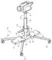
- FIG. 1is a diagrammatic perspective view, illustrating a camera mounted upon the invention, per se.
- FIG. 2is a side elevational view, illustrating the gimbal bearing assembly.
- FIG. 3is a side elevational view, illustrating movement of the gimbal bearing assembly.
- FIG. 4is a diagrammatic perspective view, illustrating the base in an alternate position, wherein the legs are retractable inward to parallel forward and rearward positions, and wherein dolly wheels are removably mounted in the legs.
- FIG. 5is a cross sectional view, illustrating the bearing sleeve of the gimbal bearing assembly.
- FIG. 6is a top plan view, illustrating retractability of the legs of the base and relative motion between the extended and retracted positions.
- FIG. 1illustrates a camera support 10 , comprising a base 12 , a camera mount 14 , and a vertical support 16 extending between the base 12 and camera mount 14 .
- a camera 15is shown mounted to the camera mount 14 .
- the base 12has four legs 18 extending outward therefrom.
- a gimbal bearing assembly 20is located on the vertical support 16 between the base 12 and camera mount 14 .
- the vertical support 16preferably comprises telescoping sections 22 which allow adjustment of the distance between the base 12 and camera mount 14 .
- the telescoping sections 22are typically a pair of coaxial tubes of slightly different sizes.
- the telescoping sections 22may be fixed in a suitable relative position by twisting, set screws, or any other scheme which allows the relative position of such telescoping tubes to be maintained, as is well known by those of skill in the art, and accordingly is beyond the scope of this discussion.
- the telescoping sections 22extend above the gimbal bearing assembly 20
- the vertical support 16further comprises a lower support 23 which extends below the gimbal bearing assembly 20 and is a tube that is coaxial with the telescoping sections 22 .
- the base 12includes a central plate 24 and a pair of outer plates 26 .
- the outer plates 26each have a sleeve 28 which allows the central plate 24 to slide therein, such that the outer plates 26 are capable of movement toward and away from each other, effectively lengthening or shortening the base 12 .
- the baseincludes a pair of plate tighteners 29 , each preferably being a tightening screw located on one of the outer plates 26 , in communication with the sleeve 28 thereof, so as to tighten against the central plate 24 located within said sleeve 28 and prevent relative movement of the central plate 24 with respect to said outer plate 26 .
- the relative movement of the outer plates 26 in the horizontal planeallow overall weight distribution of the base 12 to be adjusted. Accordingly, components of the base 12 can be customized to act as a counterweight for the camera 15 .
- the gimbal bearing assembly 20is located on the vertical support 16 between the base 12 and camera mount 14 .
- the gimbal bearing assembly 20comprises an outer sleeve 30 having an outer sleeve top 30 T, an inner sleeve 32 , and a handgrip, which may include a flange 34 mounted to the outer sleeve 30 at the outer sleeve top 30 T and/or a handle bar 36 extending radially from the outer sleeve 30 .
- the inner sleevehas a semispherical outer surface 35 , and an inner sleeve bore, such that the vertical support 16 extends fully through the inner sleeve bore.
- the outer sleeve 30has a semispherical inner surface 31 which mates with the semispherical outer surface 35 of the inner sleeve 32 such that the outer sleeve 30 is capable of biaxial movement upon the inner sleeve 32 , partially indicated by FIG. 3 .
- the vertical support 16is allowed to “float” within the outer sleeve 30 which helps accomplish the image stabilization goals of the invention.
- the semispherical inner surface 31 of the outer sleeve 30 and the semispherical outer surface 35 of the outer sleeve 30comprise what is commonly known as a two piece spherical bearing.
- a suitable two-piece spherical bearingis manufactured under the tradename SEALMASTER.
- SEALMASTERthe tradename SEALMASTER.
- these spherical bearingsthe BH-LS Series of heavy duty spherical bearings is preferred.
- the camera supportis held by a user by grasping the outer sleeve 30 with one hand. That hand can either hold the outer sleeve 30 directly, resting under the flange 34 , or firmly grasp the handle bar 36 , according to the embodiment of the invention and/or the preference of the user. The user can then move while holding the camera support 10 , and even vary the position of his hand with respect to the horizontal plane. The inherent weight of the base 12 and the vertical support 16 will help “right” the camera support, such that the vertical support and thus the camera will remain in a vertical position despite the hand position and accordingly the position of the outer sleeve 30 .
- the camera support 10also works effectively in a stationary mode of operation. Accordingly, the base 12 is substantially flat, and is thus capable of free-standing upon a horizontal surface. Accordingly, the camera support can function effectively as a tripod, wherein the gimbal bearing assembly 20 allows the camera to be tilted as necessary and otherwise remain still. In addition, the camera may remain mounted to the camera support 10 even when the camera is not in use or when it is being transported. Further, many modern digital cameras provide for connectivity to personal computers. In accordance therewith, the camera can easily sit alongside a computer desk, held at desk height by the camera support, while images from the camera are downloaded to the computer.
- FIG. 4 and FIG. 6illustrate various modes and positions for the base 12 .
- the legs 18are pivotable within the horizontal plane, and are capable of moving between various positions, including an extended position, as shown in FIG. 1 and in full lines in FIG. 6, and a retracted position, as shown in full lines in FIG. 4 and in phantom in FIG. 6 .
- the legs 18In the retracted position, the legs 18 all extend parallel to each other, such that a pair of the legs extend forwardly of the base 12 of the camera support 10 , and a pair of the legs extend rearwardly of the base 12 .
- the legs 18can be configured to extend fully laterally (to the side), such that all legs 18 extend parallel to each other, and all legs are perpendicular to their retracted position shown in FIG. 4 .
- dolly wheels 40are removably mountable to the legs 18 .
- the legs 18each have an extremity 18 E located on each legs 18 nearly fully opposite from the base 12 .
- a bore 19may be located at the extremity 18 E to facilitate selective mounting and removal of the dolly wheels 40 .
- the dolly wheels 40thus allow a further mode of mobile operation for the camera support 10 .
- the various positions of the legs 18allow for various effective widths between the wheels 40 . Varying the effective width, and the ability to attach different types of wheels 40 onto the legs also allows the camera support 10 to be used with various track or rail systems often employed in video and motion picture production.
- FIG. 4illustrates the camera mount 14 , and the manner of attaching the camera 15 thereto.
- the camera mount 14comprises a vertical threaded rod 50 , extending coaxially upward from the vertical support 16 .
- a camera mounting nut 52extends on the vertical threaded rod 50 for tightening up against the camera 15 once the camera 15 is fully threaded onto the vertical threaded rod 50 .
Landscapes
- Engineering & Computer Science (AREA)
- General Engineering & Computer Science (AREA)
- Mechanical Engineering (AREA)
- Accessories Of Cameras (AREA)
- Studio Devices (AREA)
Abstract
Description
The invention relates to a video camera support device. More particularly, the invention relates to a device which supports a video camera and allows the camera to be operated while stationary as well as while in motion, wherein the camera is stabilized so that motion artifacts are smoothed or eliminated by the device.
A primary goal among both professional and amateur videographers is maintaining a jitter free image. Even when the videographer stands still, the relatively light weight of modern cameras make it easy for shaking and minute hand movements to translate to a jumpy image. But, when the videographer chooses to walk while shooting, the image will often be downright dizzying to the viewer. Only professionals and extremely experienced amateurs can actually walk with the camera and maintain fluid motion and a stabilized image.
One advance in professional videography is the so-called “STEADICAM”, stemming from U.S. Pat. Nos. 4,017,168 and 4,156,512 to Brown. The STEADICAM is a large device which helps a camera operator move around the subject while filming with relative ease, while maintaining fluid camera movement. However, while it can effectively maintain fluidity while moving, the STEADICAM does not allow the camera to be held perfectly still. The camera is always “floating”. Also, The STEADICAM is quite heavy, yet does not allow the operator to set it down on the ground at any time. In addition, the complexity of the STEADICAM makes it too expensive for amateurs. In addition, the STEADICAM does not allow the camera to be raised above the arm reach of the operator, seriously limiting its use in filming “bird's eye” camera angles.
U.S. Pat. No. 4,474,439 to Brown discloses another camera support design which provides support for the “electronics package”, a monitor, a battery, and other auxiliary equipment. This design is too complex and thus too expensive for the amateur videographer. Further, the design is configured specifically for supporting auxiliary equipment. Modern video cameras are generally self-contained, and require that the operator carry little or no additional equipment.
Other camera stabilizing and support devices are disclosed in U.S. Pat. No. 4,657,267 to Jaumann; U.S. Pat. No. 4,699,484 to Howell; U.S. Pat. No. 5,429,332 to Ishikawa; and U.S. Pat. No. 5,650,820 to Hewlett. While these units may be suitable for the particular purpose employed, or for general use, they would not be as suitable for the purposes of the present invention as disclosed hereafter.
It is an object of the invention to provide a video camera support which allows a video camera to be mounted thereto, and then allows a variety of operation modes, allowing for both stationary and mobile videography. Advantageously, the videographer need not remove the camera from the camera support while using the camera in various modes of operation, and even when the camera is not is use. Accordingly, the camera has a camera mount on its upper end, and has a base at its lower end which allows the camera to be supported in a free-standing position.
It is another object of the invention that the camera support stabilizes motion of the camera, reducing jitter and motion artifacts. Accordingly, the combined structural configuration, weighting, adjustability of the base, and gimbal bearing act to reduce camera shaking, increase fluidity of motion, and thus stabilize the acquired image.
It is another object of the invention that dolly wheels are detachably mountable to the base to provide a further mode of usage. Accordingly, the legs fold forward and rearwardly into parallel positions, and allow dolly wheels to be removably attached at extremities thereof.
The invention is a camera support for allowing stationary and stabilized mobile use of a video camera, comprising a base which is capable of free-standing upon a horizontal surface, a camera mount, and a vertical support extending between the base and camera mount. A gimbal bearing assembly is located on the vertical support, having an outer sleeve which is biaxially movable with respect to the vertical support, so that the entire camera support can be supported by the user holding the outer sleeve, allowing the user to move while the vertical support remains stabilized in an upright position. The base has a tripartite construction which is adjustable to balance the camera weight and has retractable legs to which dolly wheels may be removably mounted for an additional mode of mobile operation.
To the accomplishment of the above and related objects the invention may be embodied in the form illustrated in the accompanying drawings. Attention is called to the fact, however, that the drawings are illustrative only. Variations are contemplated as being part of the invention, limited only
In the drawings, like elements are depicted by like reference numerals. The drawings are briefly described as follows.
FIG. 1 is a diagrammatic perspective view, illustrating a camera mounted upon the invention, per se.
FIG. 2 is a side elevational view, illustrating the gimbal bearing assembly.
FIG. 3 is a side elevational view, illustrating movement of the gimbal bearing assembly.
FIG. 4 is a diagrammatic perspective view, illustrating the base in an alternate position, wherein the legs are retractable inward to parallel forward and rearward positions, and wherein dolly wheels are removably mounted in the legs.
FIG. 5 is a cross sectional view, illustrating the bearing sleeve of the gimbal bearing assembly.
FIG. 6 is a top plan view, illustrating retractability of the legs of the base and relative motion between the extended and retracted positions.
FIG. 1 illustrates acamera support 10, comprising abase 12, acamera mount 14, and avertical support 16 extending between thebase 12 andcamera mount 14. Acamera 15 is shown mounted to thecamera mount 14. Thebase 12 has fourlegs 18 extending outward therefrom. Agimbal bearing assembly 20 is located on thevertical support 16 between thebase 12 andcamera mount 14.
Thevertical support 16 preferably comprisestelescoping sections 22 which allow adjustment of the distance between thebase 12 andcamera mount 14. Thetelescoping sections 22 are typically a pair of coaxial tubes of slightly different sizes. Thetelescoping sections 22 may be fixed in a suitable relative position by twisting, set screws, or any other scheme which allows the relative position of such telescoping tubes to be maintained, as is well known by those of skill in the art, and accordingly is beyond the scope of this discussion. Preferably, thetelescoping sections 22 extend above thegimbal bearing assembly 20, and thevertical support 16 further comprises alower support 23 which extends below thegimbal bearing assembly 20 and is a tube that is coaxial with thetelescoping sections 22.
Thebase 12 includes acentral plate 24 and a pair ofouter plates 26. Theouter plates 26 each have asleeve 28 which allows thecentral plate 24 to slide therein, such that theouter plates 26 are capable of movement toward and away from each other, effectively lengthening or shortening thebase 12. The base includes a pair ofplate tighteners 29, each preferably being a tightening screw located on one of theouter plates 26, in communication with thesleeve 28 thereof, so as to tighten against thecentral plate 24 located within saidsleeve 28 and prevent relative movement of thecentral plate 24 with respect to saidouter plate 26. The relative movement of theouter plates 26 in the horizontal plane allow overall weight distribution of thebase 12 to be adjusted. Accordingly, components of thebase 12 can be customized to act as a counterweight for thecamera 15.
With simultaneous reference to FIG. 1, FIG. 2, and FIG. 5, thegimbal bearing assembly 20 is located on thevertical support 16 between thebase 12 andcamera mount 14. Thegimbal bearing assembly 20 comprises anouter sleeve 30 having anouter sleeve top 30T, aninner sleeve 32, and a handgrip, which may include aflange 34 mounted to theouter sleeve 30 at theouter sleeve top 30T and/or ahandle bar 36 extending radially from theouter sleeve 30. The inner sleeve has a semisphericalouter surface 35, and an inner sleeve bore, such that thevertical support 16 extends fully through the inner sleeve bore. Theouter sleeve 30 has a semisphericalinner surface 31 which mates with the semisphericalouter surface 35 of theinner sleeve 32 such that theouter sleeve 30 is capable of biaxial movement upon theinner sleeve 32, partially indicated by FIG.3. In essence, thevertical support 16 is allowed to “float” within theouter sleeve 30 which helps accomplish the image stabilization goals of the invention.
The semisphericalinner surface 31 of theouter sleeve 30 and the semisphericalouter surface 35 of theouter sleeve 30 comprise what is commonly known as a two piece spherical bearing. A suitable two-piece spherical bearing is manufactured under the tradename SEALMASTER. Among these spherical bearings, the BH-LS Series of heavy duty spherical bearings is preferred.
When thebase 12 is properly balanced, the camera support is held by a user by grasping theouter sleeve 30 with one hand. That hand can either hold theouter sleeve 30 directly, resting under theflange 34, or firmly grasp thehandle bar 36, according to the embodiment of the invention and/or the preference of the user. The user can then move while holding thecamera support 10, and even vary the position of his hand with respect to the horizontal plane. The inherent weight of thebase 12 and thevertical support 16 will help “right” the camera support, such that the vertical support and thus the camera will remain in a vertical position despite the hand position and accordingly the position of theouter sleeve 30. In addition, rapid “side-to-side” movements are smoothed, as the inertia of the overall camera support interacts with the gimbal bearing so that thevertical support 16 fluidly lags but follows the hand motion at theouter sleeve 30 and then returns to its upright equilibrium position. In addition, the weight and inertia of the camera support stops jitters which otherwise occur from minute hand movements when holding a lightweight camera. It should also be noted that the handle bar can alternatively or additionally be attached to thevertical support 16 to provide a slight steering of the vertical support while primary support is provided by the user at theouter sleeve 30.
Thecamera support 10 also works effectively in a stationary mode of operation. Accordingly, thebase 12 is substantially flat, and is thus capable of free-standing upon a horizontal surface. Accordingly, the camera support can function effectively as a tripod, wherein thegimbal bearing assembly 20 allows the camera to be tilted as necessary and otherwise remain still. In addition, the camera may remain mounted to thecamera support 10 even when the camera is not in use or when it is being transported. Further, many modern digital cameras provide for connectivity to personal computers. In accordance therewith, the camera can easily sit alongside a computer desk, held at desk height by the camera support, while images from the camera are downloaded to the computer.
FIG.4 and FIG. 6 illustrate various modes and positions for thebase 12. In particular, thelegs 18 are pivotable within the horizontal plane, and are capable of moving between various positions, including an extended position, as shown in FIG.1 and in full lines in FIG. 6, and a retracted position, as shown in full lines in FIG.4 and in phantom in FIG.6. In the retracted position, thelegs 18 all extend parallel to each other, such that a pair of the legs extend forwardly of thebase 12 of thecamera support 10, and a pair of the legs extend rearwardly of thebase 12. It should be further noted that in addition to the positions shown, thelegs 18 can be configured to extend fully laterally (to the side), such that alllegs 18 extend parallel to each other, and all legs are perpendicular to their retracted position shown in FIG.4.
Also illustrated in FIG.1 and FIG. 4,dolly wheels 40 are removably mountable to thelegs 18. In particular, thelegs 18 each have anextremity 18E located on eachlegs 18 nearly fully opposite from thebase 12. A bore19 may be located at theextremity 18E to facilitate selective mounting and removal of thedolly wheels 40. Thedolly wheels 40 thus allow a further mode of mobile operation for thecamera support 10. In addition the various positions of thelegs 18 allow for various effective widths between thewheels 40. Varying the effective width, and the ability to attach different types ofwheels 40 onto the legs also allows thecamera support 10 to be used with various track or rail systems often employed in video and motion picture production.
FIG. 4 illustrates thecamera mount 14, and the manner of attaching thecamera 15 thereto. Thecamera mount 14 comprises a vertical threadedrod 50, extending coaxially upward from thevertical support 16. Acamera mounting nut 52 extends on the vertical threadedrod 50 for tightening up against thecamera 15 once thecamera 15 is fully threaded onto the vertical threadedrod 50.
In conclusion, herein is presented a camera support for holding a camera during both stationary and mobile filming, such that the camera is effectively stabilized during mobile use thereof. In furtherance of the goals of the invention, said invention has been illustrated by example in the accompanying drawing figures and throughout the written description. It should be appreciated though, that numerous variations are possible, while adhering to the inventive concept. Such variations are contemplated as being a part of the present invention.
Claims (7)
1. A camera support, for selectively supporting a camera upon a horizontal plane and allowing stabilized movement of said camera, comprising:
a camera mount for allowing a camera to be mounted thereupon;
a base, the base capable of resting on the horizontal plane, the base having a central plate, the vertical support rigidly mounted upon the central plate, a pair of outer plates, the outer plates each having a sleeve such that the central plate is slidably mounted within said sleeves such that the outer plates can be moved toward and away from each other by moving the central plate within the sleeves of said outer plates to alter weight distribution of said base to act as a counterbalance for the camera when mounted in the camera mount;
a vertical support extending between the base and camera mount, the vertical support adjustable in length; and
a gimbal bearing assembly, having an outer sleeve and a two piece spherical bearing, the two piece spherical bearing connected between the vertical support and the outer sleeve such that the outer sleeve may be held by the user while the vertical support can move with respect thereto in order to remain substantially vertical.
2. The camera support as recited inclaim 1 , wherein the vertical support comprises a pair of telescoping sections located above the gimbal bearing assembly for adjusting relative positioning of the camera mount and base, and a fixed lower section located below the gimbal bearing assembly.
3. The camera support as recited inclaim 2 , wherein the two piece spherical bearing further comprises an inner sleeve having a semispherical outer surface, wherein the outer sleeve comprises a semispherical inner surface, and wherein the semispherical outer surface of the inner sleeve engages the semispherical inner surface of the outer sleeve to allow biaxial relative movement of the outer sleeve upon the inner sleeve.
4. The camera support as recited inclaim 3 , wherein the base is capable of resting in a free-standing fashion upon a horizontal plane and further comprises four legs, each of the legs pivotally mounted to one of the outer plates, the legs extending outward from the base and parallel to said base, the legs capable of pivoting within the horizontal plane.
5. The camera support as recited inclaim 4 , wherein the base further comprises a pair of plate tighteners located on the upper surface of the outer plates, the plate tighteners in communication with the sleeve of its associated outer plate for tightening against the central plate and fixing relative positioning of the said outer plate and the central plate.
6. The camera support as recited inclaim 5 , wherein the legs have an extended position, and a retracted position wherein the legs all extend parallel, wherein two of the legs extend forwardly and the other two legs extend rearwardly.
7. The camera support as recited inclaim 6 , wherein the legs each have an extremity, located opposite from the base, and wherein wheels are removably mounted at the extremity.
Priority Applications (1)
| Application Number | Priority Date | Filing Date | Title |
|---|---|---|---|
| US09/684,774US6439515B1 (en) | 2000-10-10 | 2000-10-10 | Video camera support device |
Applications Claiming Priority (1)
| Application Number | Priority Date | Filing Date | Title |
|---|---|---|---|
| US09/684,774US6439515B1 (en) | 2000-10-10 | 2000-10-10 | Video camera support device |
Publications (1)
| Publication Number | Publication Date |
|---|---|
| US6439515B1true US6439515B1 (en) | 2002-08-27 |
Family
ID=24749508
Family Applications (1)
| Application Number | Title | Priority Date | Filing Date |
|---|---|---|---|
| US09/684,774Expired - Fee RelatedUS6439515B1 (en) | 2000-10-10 | 2000-10-10 | Video camera support device |
Country Status (1)
| Country | Link |
|---|---|
| US (1) | US6439515B1 (en) |
Cited By (78)
| Publication number | Priority date | Publication date | Assignee | Title |
|---|---|---|---|---|
| US20040001137A1 (en)* | 2002-06-27 | 2004-01-01 | Ross Cutler | Integrated design for omni-directional camera and microphone array |
| US6746029B2 (en)* | 2002-02-15 | 2004-06-08 | Taiwan Semiconductor Manufacturing Co., Ltd | Photograph vehicle |
| US20040109573A1 (en)* | 2002-09-19 | 2004-06-10 | Yamaha Corporation | Electro-acoustic apparatus |
| US20040135879A1 (en)* | 2003-01-03 | 2004-07-15 | Stacy Marco A. | Portable wireless indoor/outdoor camera |
| US6773110B1 (en) | 2003-05-09 | 2004-08-10 | Charles H. Gale | Camera stabilizer platform and camcorder therefor |
| US20040223753A1 (en)* | 2003-05-09 | 2004-11-11 | Gale Charles H. | Camera stabilizer platform and camcorder therefor |
| US20040245417A1 (en)* | 2001-11-14 | 2004-12-09 | De'longhi Giuseppe | Support for a radiator |
| US20050115137A1 (en)* | 2003-11-03 | 2005-06-02 | Minneman Steven W. | Shooter's rest |
| US20050117052A1 (en)* | 2003-12-02 | 2005-06-02 | Wilife Inc. | Network camera mounting system |
| US20050230573A1 (en)* | 2003-05-23 | 2005-10-20 | Peter Ligertwood | Stand |
| USD519183S1 (en) | 2003-11-03 | 2006-04-18 | Minneman Steven W | Shooter's rest |
| US20060233544A1 (en)* | 2005-04-11 | 2006-10-19 | Roman Coppola | Bipod platform system for a camera |
| US7140622B1 (en)* | 2003-03-25 | 2006-11-28 | Cantu Richard A | Movie camera skate dolly |
| US20070205639A1 (en)* | 2006-03-03 | 2007-09-06 | Mattel, Inc. | Adjustable Child Support Device |
| US20080226284A1 (en)* | 2005-04-11 | 2008-09-18 | Roman Coppola | Bipod Platform System for a Camera |
| US20080239638A1 (en)* | 2007-03-26 | 2008-10-02 | The Bank Of Tokyo-Mitsubishi Ufj, Ltd. | Display device stand |
| US20080288125A1 (en)* | 2007-05-15 | 2008-11-20 | Cameron John F | Determining an autonomous position of a point of interest on a lifting device |
| US20090083100A1 (en)* | 2007-09-26 | 2009-03-26 | Darby Jr George Derrick | Collision avoidance |
| RU2362195C1 (en)* | 2008-03-25 | 2009-07-20 | Ральф Роландович Келли | Movable stabilised mounting for panoramic film shooting |
| US20090212194A1 (en)* | 2008-02-08 | 2009-08-27 | Dennis Wood | Camera Dolly |
| US7631877B2 (en) | 2006-01-26 | 2009-12-15 | Battenfeld Technologies, Inc. | Firearm targets and methods for manufacturing firearm targets |
| WO2009156745A1 (en)* | 2008-06-26 | 2009-12-30 | The Vitec Group Plc | Methods of stabilising recorded or projected images in optical apparatus |
| US20100039262A1 (en)* | 2008-08-18 | 2010-02-18 | Cameron John F | Construction equipment component location tracking |
| US20100039319A1 (en)* | 2008-08-18 | 2010-02-18 | Cameron John F | Automated recordation of crane inspection activity |
| US7681886B2 (en) | 2006-02-24 | 2010-03-23 | Battenfeld Technologies, Inc. | Shooting gallery devices and methods |
| US20100098405A1 (en)* | 2005-04-11 | 2010-04-22 | Roman Coppola | Monopole Platform System for a Camera |
| US7708250B1 (en)* | 2008-02-19 | 2010-05-04 | Dein Alan J | Ceiling panel support apparatus |
| US7726478B2 (en) | 2006-02-27 | 2010-06-01 | Battenfeld Technologies, Inc. | Containers for carrying firearm accessories and/or supporting firearms |
| US7730824B1 (en)* | 2007-07-31 | 2010-06-08 | Black Robert O | Precision tactical mount |
| US7774972B2 (en) | 2006-09-11 | 2010-08-17 | Battenfeld Technologies, Inc. | Modular shooting rests and shooting rest assemblies |
| US7779572B2 (en) | 2006-05-08 | 2010-08-24 | Battenfeld Technologies, Inc. | Bipod device for use with a firearm |
| US7789356B1 (en)* | 2006-11-14 | 2010-09-07 | Jones Steven P | Stand assembly for an optical device |
| US7794160B1 (en) | 2008-11-18 | 2010-09-14 | Janice Arthur | Support system for a camera stabilizing device |
| US7823317B2 (en) | 2006-08-22 | 2010-11-02 | Battenfeld Technologies, Inc. | Adjustable shooting rests and shooting rest assemblies |
| US20100283681A1 (en)* | 2008-01-07 | 2010-11-11 | Benjamin William Remondi | Autonomous projection of global navigation satellite orbits |
| US7845267B2 (en) | 2007-09-11 | 2010-12-07 | Battenfield Technologies, Inc. | Attachment mechanisms for coupling firearms to supporting structures |
| US20100328449A1 (en)* | 2009-06-26 | 2010-12-30 | Hong Fu Jin Precision Industry (Shenzhen) Co., Ltd. | Support stand and imaging measurement device using the same |
| US20110081020A1 (en)* | 2008-04-09 | 2011-04-07 | Peter Van Wyck Loomis | Terrestial-signal based exclusion zone compliance |
| US7946071B2 (en) | 2004-11-10 | 2011-05-24 | Battenfeld Technologies, Inc. | Firearm vise |
| US7954272B2 (en) | 2007-05-08 | 2011-06-07 | Battenfeld Technologies, Inc. | Adjustable firearm supports and associated methods of use and manufacture |
| US7997021B2 (en) | 2008-11-21 | 2011-08-16 | Battenfeld Technologies | Shooting rests with adjustable height assemblies |
| US8011129B2 (en) | 2003-06-13 | 2011-09-06 | Battenfeld Technologies, Inc. | Recoil-reducing shooting rest |
| US8103438B2 (en) | 2007-09-26 | 2012-01-24 | Trimble Navigation Limited | Method and system for automatically directing traffic on a site |
| US8104212B2 (en) | 2006-02-24 | 2012-01-31 | Battenfeld Technologies, Inc. | Firearm supports, such as shooting bags, and firearm support assemblies |
| US8296988B2 (en) | 2006-11-30 | 2012-10-30 | Battenfeld Technologies, Inc. | Firearm supporting devices, methods of assembling firearm supporting devices, and methods of packaging firearm supporting devices |
| USD670752S1 (en) | 2008-09-18 | 2012-11-13 | Edward Barber | Portable camera mount |
| US20120287336A1 (en)* | 2011-05-13 | 2012-11-15 | Justin Jensen | Systems and methods for coupling components |
| US8336708B2 (en) | 2007-07-20 | 2012-12-25 | Battenfeld Technologies, Inc. | System and container for organizing and carrying tools and tool sets |
| US8371057B2 (en) | 2006-05-09 | 2013-02-12 | Battenfeld Technologies, Inc. | Firearm cleaning apparatus with protective coating |
| US8584995B2 (en) | 2010-12-07 | 2013-11-19 | Sean Anthony Joseph Russell | Versatile camera support mount |
| US8621773B2 (en) | 2003-06-13 | 2014-01-07 | Battenfeld Technologies, Inc. | Shooting rests for supporting firearms |
| US8695985B2 (en) | 2011-01-07 | 2014-04-15 | Battenfeld Technologies, Inc. | Stowable shooting target assemblies |
| FR3000976A1 (en)* | 2013-01-11 | 2014-07-18 | Idee Bat Mediterranee | Device for supporting ergonomic unit e.g. beam, in industrial tool, has four feet cooperating with base, where longitudinal axes of foot and longitudinal axes of feet describe directed angle whose absolute value is higher than given value |
| EP2643730A4 (en)* | 2010-11-25 | 2014-10-08 | Resolution Art Inc | An imaging robot |
| US8931201B2 (en) | 2012-12-31 | 2015-01-13 | Battenfeld Technologies, Inc. | Gun support apparatus |
| US20150240988A1 (en)* | 2014-02-08 | 2015-08-27 | Franklin B. White | Theft resistant upstanding mount for temporary positioning of costly equipment at unattended outdoor locations |
| US20150292226A1 (en)* | 2014-02-08 | 2015-10-15 | Franklin B. White | Theft resistant upstanding mount for temporary positioning of costly equipment at unattended outdoor locations |
| CN106341587A (en)* | 2016-10-26 | 2017-01-18 | 许云龙 | Simple yet highly effective VR recorder |
| CN106531017A (en)* | 2016-12-22 | 2017-03-22 | 天津伟联展具有限公司 | Exhibition appliance base |
| US9638986B1 (en)* | 2015-11-03 | 2017-05-02 | Chapman/Leonard Studio Equipment, Inc. | Mobile base for a camera crane |
| CN106899831A (en)* | 2017-02-28 | 2017-06-27 | 刘腾龙 | A kind of entertaining bird appreciation platform |
| US9702653B2 (en) | 2015-10-09 | 2017-07-11 | Battenfeld Technologies, Inc. | Firearm shooting rest |
| US20190219901A1 (en)* | 2005-01-07 | 2019-07-18 | Really Right Stuff, Llc | Panoramic camera mount |
| RU2705102C1 (en)* | 2019-04-08 | 2019-11-05 | Александр Юрьевич Иванов | Method of filming and system for its implementation |
| US10514225B2 (en) | 2018-01-17 | 2019-12-24 | Battenfeld Technologies, Inc. | Firearm shooting rest |
| WO2020069422A1 (en)* | 2018-09-28 | 2020-04-02 | Brainbaby Inc. | Self-contained low profile cross shooting video apparatus |
| US10782085B2 (en) | 2019-02-15 | 2020-09-22 | Aob Products Company | Recoil-reducing firearm shooting rest having tank |
| CN113719728A (en)* | 2020-05-25 | 2021-11-30 | 南京跃航台安防技术有限公司 | Wisdom safety supervision removes law enforcement device |
| US11293586B1 (en)* | 2018-10-17 | 2022-04-05 | Music Express, Llc | Boom stand |
| US11306864B1 (en)* | 2021-07-12 | 2022-04-19 | Anders Hjelset | Mobile observatory |
| US20230054231A1 (en)* | 2021-08-22 | 2023-02-23 | Alberto Del Valle Irizarry | Metal cutting device |
| US11841108B2 (en) | 2019-12-17 | 2023-12-12 | Aob Products Company | Multi-legged equipment support having leg angle adjustment |
| US12004658B2 (en) | 2021-04-15 | 2024-06-11 | Aob Products Company | Shooting rest chair |
| US20240191832A1 (en)* | 2022-12-09 | 2024-06-13 | JMJA Concepts LLC | Telescoping apparatus adapted for overhead support |
| US12015850B1 (en)* | 2021-02-17 | 2024-06-18 | Carmax Enterprise Services, Llc | Vehicle image capture systems and methods |
| US20240306816A1 (en)* | 2023-03-17 | 2024-09-19 | M3 Glass Technologies | Support assembly for a panel |
| US12320467B2 (en)* | 2022-06-14 | 2025-06-03 | New Product Development Concepts, Llc | Swivel mount assembly |
| US12390300B2 (en)* | 2022-04-24 | 2025-08-19 | Institute of Information on Traditional Chinese Medicine, China Academy of Chinese Medical Sciences. | Traditional chinese medicine inspection device of composite millimeter-wave radar |
Citations (14)
| Publication number | Priority date | Publication date | Assignee | Title |
|---|---|---|---|---|
| US1272574A (en)* | 1917-06-14 | 1918-07-16 | Thomas Oberkirch Company Ltd | Support for cameras, machine-guns, and the like. |
| US1559716A (en)* | 1924-07-03 | 1925-11-03 | George W Lingle | Surveyor's instrument |
| US4156512A (en) | 1974-09-16 | 1979-05-29 | Brown Garrett W | Equipment support system |
| US4158490A (en)* | 1976-11-11 | 1979-06-19 | Panavision, Incorporated | Body-mounted support device for motion picture camera |
| US4474439A (en) | 1982-01-26 | 1984-10-02 | Brown Garrett W | Camera support |
| US4625938A (en) | 1983-10-24 | 1986-12-02 | Brown Garrett W | Suspension system for supporting and conveying equipment, such as a camera |
| US4657267A (en) | 1984-09-19 | 1987-04-14 | Sachtler Gmbh Filmtechnische Geraete | Motion picture or television camera stand |
| US4699484A (en) | 1985-11-15 | 1987-10-13 | Howell Mary E | Rail mounted camera system |
| US4926561A (en)* | 1987-06-08 | 1990-05-22 | Miller Donald P | Tripod stand for a surveyor's rod |
| US5429332A (en) | 1991-08-09 | 1995-07-04 | Heiwa Seiki Kogyo Co., Ltd. | Sliding plate for securing camera |
| US5650821A (en) | 1995-05-09 | 1997-07-22 | Hewlett; Kenneth | Video camera support with counterbalance |
| US5749549A (en)* | 1995-12-29 | 1998-05-12 | Javad Positioning, Llc | Satellite positioning system antenna supporting tripod |
| US5963749A (en)* | 1998-02-09 | 1999-10-05 | Nicholson; Lynn | Self-leveling invertible camera stabilizer |
| US6293676B1 (en)* | 1998-02-17 | 2001-09-25 | Garrett W. Brown | Camera support including extendable post |
- 2000
- 2000-10-10USUS09/684,774patent/US6439515B1/ennot_activeExpired - Fee Related
Patent Citations (14)
| Publication number | Priority date | Publication date | Assignee | Title |
|---|---|---|---|---|
| US1272574A (en)* | 1917-06-14 | 1918-07-16 | Thomas Oberkirch Company Ltd | Support for cameras, machine-guns, and the like. |
| US1559716A (en)* | 1924-07-03 | 1925-11-03 | George W Lingle | Surveyor's instrument |
| US4156512A (en) | 1974-09-16 | 1979-05-29 | Brown Garrett W | Equipment support system |
| US4158490A (en)* | 1976-11-11 | 1979-06-19 | Panavision, Incorporated | Body-mounted support device for motion picture camera |
| US4474439A (en) | 1982-01-26 | 1984-10-02 | Brown Garrett W | Camera support |
| US4625938A (en) | 1983-10-24 | 1986-12-02 | Brown Garrett W | Suspension system for supporting and conveying equipment, such as a camera |
| US4657267A (en) | 1984-09-19 | 1987-04-14 | Sachtler Gmbh Filmtechnische Geraete | Motion picture or television camera stand |
| US4699484A (en) | 1985-11-15 | 1987-10-13 | Howell Mary E | Rail mounted camera system |
| US4926561A (en)* | 1987-06-08 | 1990-05-22 | Miller Donald P | Tripod stand for a surveyor's rod |
| US5429332A (en) | 1991-08-09 | 1995-07-04 | Heiwa Seiki Kogyo Co., Ltd. | Sliding plate for securing camera |
| US5650821A (en) | 1995-05-09 | 1997-07-22 | Hewlett; Kenneth | Video camera support with counterbalance |
| US5749549A (en)* | 1995-12-29 | 1998-05-12 | Javad Positioning, Llc | Satellite positioning system antenna supporting tripod |
| US5963749A (en)* | 1998-02-09 | 1999-10-05 | Nicholson; Lynn | Self-leveling invertible camera stabilizer |
| US6293676B1 (en)* | 1998-02-17 | 2001-09-25 | Garrett W. Brown | Camera support including extendable post |
Non-Patent Citations (1)
| Title |
|---|
| SKF Product Service Guide, pp. 171, 235, Apr. 1992. |
Cited By (126)
| Publication number | Priority date | Publication date | Assignee | Title |
|---|---|---|---|---|
| US7165751B2 (en)* | 2001-11-14 | 2007-01-23 | De' Longhi S.P.A. | Support for a radiator |
| US20040245417A1 (en)* | 2001-11-14 | 2004-12-09 | De'longhi Giuseppe | Support for a radiator |
| US6746029B2 (en)* | 2002-02-15 | 2004-06-08 | Taiwan Semiconductor Manufacturing Co., Ltd | Photograph vehicle |
| US20040001137A1 (en)* | 2002-06-27 | 2004-01-01 | Ross Cutler | Integrated design for omni-directional camera and microphone array |
| US7852369B2 (en)* | 2002-06-27 | 2010-12-14 | Microsoft Corp. | Integrated design for omni-directional camera and microphone array |
| US7616770B2 (en)* | 2002-09-19 | 2009-11-10 | Yamaha Corporation | Electro-acoustic apparatus |
| US20040109573A1 (en)* | 2002-09-19 | 2004-06-10 | Yamaha Corporation | Electro-acoustic apparatus |
| US20040135879A1 (en)* | 2003-01-03 | 2004-07-15 | Stacy Marco A. | Portable wireless indoor/outdoor camera |
| US7140622B1 (en)* | 2003-03-25 | 2006-11-28 | Cantu Richard A | Movie camera skate dolly |
| US20040223753A1 (en)* | 2003-05-09 | 2004-11-11 | Gale Charles H. | Camera stabilizer platform and camcorder therefor |
| US6862407B2 (en) | 2003-05-09 | 2005-03-01 | Charles H. Gale | Camera stabilizer platform and camcorder therefor |
| US20040223081A1 (en)* | 2003-05-09 | 2004-11-11 | Gale Charles H. | Camera stabilizer platform and camcorder therefor |
| US6773110B1 (en) | 2003-05-09 | 2004-08-10 | Charles H. Gale | Camera stabilizer platform and camcorder therefor |
| US20050230573A1 (en)* | 2003-05-23 | 2005-10-20 | Peter Ligertwood | Stand |
| US7261261B2 (en)* | 2003-05-23 | 2007-08-28 | Peter Ligertwood | Stand of free standing or mobile type |
| US10859336B2 (en) | 2003-06-13 | 2020-12-08 | Aob Products Company | Shooting rests for supporting firearms |
| US10317162B2 (en) | 2003-06-13 | 2019-06-11 | Battenfeld Technologies, Inc. | Shooting rests for supporting firearms |
| US8011129B2 (en) | 2003-06-13 | 2011-09-06 | Battenfeld Technologies, Inc. | Recoil-reducing shooting rest |
| US9151561B2 (en) | 2003-06-13 | 2015-10-06 | Battenfeld Technologies, Inc. | Shooting rests for supporting firearms |
| US8621773B2 (en) | 2003-06-13 | 2014-01-07 | Battenfeld Technologies, Inc. | Shooting rests for supporting firearms |
| USD519183S1 (en) | 2003-11-03 | 2006-04-18 | Minneman Steven W | Shooter's rest |
| US20050115137A1 (en)* | 2003-11-03 | 2005-06-02 | Minneman Steven W. | Shooter's rest |
| US20050117052A1 (en)* | 2003-12-02 | 2005-06-02 | Wilife Inc. | Network camera mounting system |
| US8578645B2 (en) | 2004-11-10 | 2013-11-12 | Battenfeld Technologies, Inc. | Firearm vise |
| US7946071B2 (en) | 2004-11-10 | 2011-05-24 | Battenfeld Technologies, Inc. | Firearm vise |
| US10585337B2 (en)* | 2005-01-07 | 2020-03-10 | Really Right Stuff, Llc | Panoramic camera mount |
| US20190219901A1 (en)* | 2005-01-07 | 2019-07-18 | Really Right Stuff, Llc | Panoramic camera mount |
| US11036116B2 (en) | 2005-01-07 | 2021-06-15 | Really Right Stuff, Llc | Panoramic camera mount |
| US11237463B2 (en) | 2005-01-07 | 2022-02-01 | Really Right Stuff, Llc | Panoramic camera mount |
| US11614677B2 (en) | 2005-01-07 | 2023-03-28 | Really Right Stuff, Llc | Panoramic camera mount |
| US20230194962A1 (en)* | 2005-01-07 | 2023-06-22 | Really Right Stuff, Llc | Panoramic camera mount |
| US11809068B2 (en)* | 2005-01-07 | 2023-11-07 | Really Right Stuff, Llc | Panoramic camera mount |
| US7628552B2 (en) | 2005-04-11 | 2009-12-08 | Roman Coppola | Bipod platform system for a camera |
| US20100098405A1 (en)* | 2005-04-11 | 2010-04-22 | Roman Coppola | Monopole Platform System for a Camera |
| US20080226284A1 (en)* | 2005-04-11 | 2008-09-18 | Roman Coppola | Bipod Platform System for a Camera |
| US8021059B2 (en) | 2005-04-11 | 2011-09-20 | Roman Coppola | Monopole platform system for a camera |
| US20060233544A1 (en)* | 2005-04-11 | 2006-10-19 | Roman Coppola | Bipod platform system for a camera |
| US7631877B2 (en) | 2006-01-26 | 2009-12-15 | Battenfeld Technologies, Inc. | Firearm targets and methods for manufacturing firearm targets |
| US7681886B2 (en) | 2006-02-24 | 2010-03-23 | Battenfeld Technologies, Inc. | Shooting gallery devices and methods |
| US8104212B2 (en) | 2006-02-24 | 2012-01-31 | Battenfeld Technologies, Inc. | Firearm supports, such as shooting bags, and firearm support assemblies |
| US7726478B2 (en) | 2006-02-27 | 2010-06-01 | Battenfeld Technologies, Inc. | Containers for carrying firearm accessories and/or supporting firearms |
| US7651168B2 (en) | 2006-03-03 | 2010-01-26 | Mattel, Inc. | Adjustable child support device |
| US20070205639A1 (en)* | 2006-03-03 | 2007-09-06 | Mattel, Inc. | Adjustable Child Support Device |
| US8316570B2 (en) | 2006-05-08 | 2012-11-27 | Battenfeld Technologies, Inc. | Bipod device for use with a firearm |
| US7779572B2 (en) | 2006-05-08 | 2010-08-24 | Battenfeld Technologies, Inc. | Bipod device for use with a firearm |
| US8371057B2 (en) | 2006-05-09 | 2013-02-12 | Battenfeld Technologies, Inc. | Firearm cleaning apparatus with protective coating |
| US8356442B2 (en) | 2006-08-22 | 2013-01-22 | Battenfeld Technologies, Inc. | Adjustable shooting rests and shooting rest assemblies |
| US7823317B2 (en) | 2006-08-22 | 2010-11-02 | Battenfeld Technologies, Inc. | Adjustable shooting rests and shooting rest assemblies |
| US8132351B2 (en) | 2006-08-22 | 2012-03-13 | Battenfeld Technologies, Inc. | Adjustable shooting rests and shooting rest assemblies |
| US7774972B2 (en) | 2006-09-11 | 2010-08-17 | Battenfeld Technologies, Inc. | Modular shooting rests and shooting rest assemblies |
| US7789356B1 (en)* | 2006-11-14 | 2010-09-07 | Jones Steven P | Stand assembly for an optical device |
| US8296988B2 (en) | 2006-11-30 | 2012-10-30 | Battenfeld Technologies, Inc. | Firearm supporting devices, methods of assembling firearm supporting devices, and methods of packaging firearm supporting devices |
| USD642183S1 (en) | 2007-03-26 | 2011-07-26 | The Bank Of Tokyo-Mitsubishi Ufj, Ltd. | Display device stand |
| US20080239638A1 (en)* | 2007-03-26 | 2008-10-02 | The Bank Of Tokyo-Mitsubishi Ufj, Ltd. | Display device stand |
| US7954272B2 (en) | 2007-05-08 | 2011-06-07 | Battenfeld Technologies, Inc. | Adjustable firearm supports and associated methods of use and manufacture |
| US20080288125A1 (en)* | 2007-05-15 | 2008-11-20 | Cameron John F | Determining an autonomous position of a point of interest on a lifting device |
| US9156167B2 (en) | 2007-05-15 | 2015-10-13 | Trimble Navigation Limited | Determining an autonomous position of a point of interest on a lifting device |
| US8336708B2 (en) | 2007-07-20 | 2012-12-25 | Battenfeld Technologies, Inc. | System and container for organizing and carrying tools and tool sets |
| US7730824B1 (en)* | 2007-07-31 | 2010-06-08 | Black Robert O | Precision tactical mount |
| US8464628B2 (en) | 2007-09-11 | 2013-06-18 | Battenfeld Technologies, Inc. | Attachment mechanisms for coupling firearms to supporting structures |
| US7845267B2 (en) | 2007-09-11 | 2010-12-07 | Battenfield Technologies, Inc. | Attachment mechanisms for coupling firearms to supporting structures |
| US8103438B2 (en) | 2007-09-26 | 2012-01-24 | Trimble Navigation Limited | Method and system for automatically directing traffic on a site |
| US8144000B2 (en) | 2007-09-26 | 2012-03-27 | Trimble Navigation Limited | Collision avoidance |
| US8239125B2 (en) | 2007-09-26 | 2012-08-07 | Trimble Navigation Limited | Method and system for automatically directing traffic on a site |
| US20090083100A1 (en)* | 2007-09-26 | 2009-03-26 | Darby Jr George Derrick | Collision avoidance |
| US8081108B2 (en) | 2008-01-07 | 2011-12-20 | Trimble Navigation Limited | Autonomous projection of global navigation satellite orbits |
| US20100283681A1 (en)* | 2008-01-07 | 2010-11-11 | Benjamin William Remondi | Autonomous projection of global navigation satellite orbits |
| US8205841B2 (en)* | 2008-02-08 | 2012-06-26 | Dennis Wood | Camera dolly |
| US20090212194A1 (en)* | 2008-02-08 | 2009-08-27 | Dennis Wood | Camera Dolly |
| US7708250B1 (en)* | 2008-02-19 | 2010-05-04 | Dein Alan J | Ceiling panel support apparatus |
| RU2362195C1 (en)* | 2008-03-25 | 2009-07-20 | Ральф Роландович Келли | Movable stabilised mounting for panoramic film shooting |
| US20110081020A1 (en)* | 2008-04-09 | 2011-04-07 | Peter Van Wyck Loomis | Terrestial-signal based exclusion zone compliance |
| US8054181B2 (en) | 2008-04-09 | 2011-11-08 | Trimble Navigation Limited | Terrestial-signal based exclusion zone compliance |
| WO2009156745A1 (en)* | 2008-06-26 | 2009-12-30 | The Vitec Group Plc | Methods of stabilising recorded or projected images in optical apparatus |
| US8224518B2 (en) | 2008-08-18 | 2012-07-17 | Trimble Navigation Limited | Automated recordation of crane inspection activity |
| US20100039262A1 (en)* | 2008-08-18 | 2010-02-18 | Cameron John F | Construction equipment component location tracking |
| US8514058B2 (en) | 2008-08-18 | 2013-08-20 | Trimble Navigation Limited | Construction equipment component location tracking |
| US20100039319A1 (en)* | 2008-08-18 | 2010-02-18 | Cameron John F | Automated recordation of crane inspection activity |
| USD670752S1 (en) | 2008-09-18 | 2012-11-13 | Edward Barber | Portable camera mount |
| US7794160B1 (en) | 2008-11-18 | 2010-09-14 | Janice Arthur | Support system for a camera stabilizing device |
| US7997021B2 (en) | 2008-11-21 | 2011-08-16 | Battenfeld Technologies | Shooting rests with adjustable height assemblies |
| US8393106B2 (en) | 2008-11-21 | 2013-03-12 | Battenfeld Technologies, Inc. | Shooting rests with adjustable height for supporting firearms |
| US8248468B2 (en)* | 2009-06-26 | 2012-08-21 | Hong Fu Jin Precision Industry (Shenzhen) Co., Ltd. | Support stand and imaging measurement device using the same |
| US20100328449A1 (en)* | 2009-06-26 | 2010-12-30 | Hong Fu Jin Precision Industry (Shenzhen) Co., Ltd. | Support stand and imaging measurement device using the same |
| US9197800B2 (en) | 2010-11-25 | 2015-11-24 | Resolution Art Inc. | Imaging robot |
| EP2643730A4 (en)* | 2010-11-25 | 2014-10-08 | Resolution Art Inc | An imaging robot |
| US8584995B2 (en) | 2010-12-07 | 2013-11-19 | Sean Anthony Joseph Russell | Versatile camera support mount |
| US8695985B2 (en) | 2011-01-07 | 2014-04-15 | Battenfeld Technologies, Inc. | Stowable shooting target assemblies |
| US20120287336A1 (en)* | 2011-05-13 | 2012-11-15 | Justin Jensen | Systems and methods for coupling components |
| US8807848B2 (en)* | 2011-05-13 | 2014-08-19 | Cinetics of Texas, LLC | Systems and methods for coupling components |
| US8931201B2 (en) | 2012-12-31 | 2015-01-13 | Battenfeld Technologies, Inc. | Gun support apparatus |
| FR3000976A1 (en)* | 2013-01-11 | 2014-07-18 | Idee Bat Mediterranee | Device for supporting ergonomic unit e.g. beam, in industrial tool, has four feet cooperating with base, where longitudinal axes of foot and longitudinal axes of feet describe directed angle whose absolute value is higher than given value |
| US20150292226A1 (en)* | 2014-02-08 | 2015-10-15 | Franklin B. White | Theft resistant upstanding mount for temporary positioning of costly equipment at unattended outdoor locations |
| US9803794B2 (en)* | 2014-02-08 | 2017-10-31 | Franklin B White | Theft resistant upstanding mount for temporary support of costly equipment likely to be a target for theft |
| US9637942B2 (en)* | 2014-02-08 | 2017-05-02 | Franklin B. White | Theft resistant upstanding mount for temporary positioning of costly equipment at unattended outdoor locations |
| US9534731B2 (en)* | 2014-02-08 | 2017-01-03 | Franklin B White | Theft resistant upstanding mount for temporary positioning of costly equipment at unattended outdoor locations |
| US20150240988A1 (en)* | 2014-02-08 | 2015-08-27 | Franklin B. White | Theft resistant upstanding mount for temporary positioning of costly equipment at unattended outdoor locations |
| US9702653B2 (en) | 2015-10-09 | 2017-07-11 | Battenfeld Technologies, Inc. | Firearm shooting rest |
| US9638986B1 (en)* | 2015-11-03 | 2017-05-02 | Chapman/Leonard Studio Equipment, Inc. | Mobile base for a camera crane |
| CN106341587A (en)* | 2016-10-26 | 2017-01-18 | 许云龙 | Simple yet highly effective VR recorder |
| CN106531017A (en)* | 2016-12-22 | 2017-03-22 | 天津伟联展具有限公司 | Exhibition appliance base |
| CN106899831A (en)* | 2017-02-28 | 2017-06-27 | 刘腾龙 | A kind of entertaining bird appreciation platform |
| CN106899831B (en)* | 2017-02-28 | 2019-08-06 | 刘腾龙 | A kind of entertaining bird appreciation platform |
| US11009306B2 (en) | 2018-01-17 | 2021-05-18 | Aob Products Company | Firearm shooting rest |
| US10514225B2 (en) | 2018-01-17 | 2019-12-24 | Battenfeld Technologies, Inc. | Firearm shooting rest |
| WO2020069422A1 (en)* | 2018-09-28 | 2020-04-02 | Brainbaby Inc. | Self-contained low profile cross shooting video apparatus |
| US11070708B2 (en) | 2018-09-28 | 2021-07-20 | Brainbaby, Inc. | Self-contained low profile cross shooting video apparatus |
| US11293586B1 (en)* | 2018-10-17 | 2022-04-05 | Music Express, Llc | Boom stand |
| US12228361B2 (en) | 2019-02-15 | 2025-02-18 | Aob Products Company | Recoil-reducing firearm shooting rest having tank |
| US10782085B2 (en) | 2019-02-15 | 2020-09-22 | Aob Products Company | Recoil-reducing firearm shooting rest having tank |
| US11333461B2 (en) | 2019-02-15 | 2022-05-17 | Aob Products Company | Recoil-reducing firearm shooting rest having tank |
| US11796274B2 (en) | 2019-02-15 | 2023-10-24 | Aob Products Company | Recoil-reducing firearm shooting rest having tank |
| RU2705102C1 (en)* | 2019-04-08 | 2019-11-05 | Александр Юрьевич Иванов | Method of filming and system for its implementation |
| US11841108B2 (en) | 2019-12-17 | 2023-12-12 | Aob Products Company | Multi-legged equipment support having leg angle adjustment |
| US12146608B2 (en) | 2019-12-17 | 2024-11-19 | Aob Products Company | Multi-legged equipment support having leg angle adjustment |
| CN113719728A (en)* | 2020-05-25 | 2021-11-30 | 南京跃航台安防技术有限公司 | Wisdom safety supervision removes law enforcement device |
| US12015850B1 (en)* | 2021-02-17 | 2024-06-18 | Carmax Enterprise Services, Llc | Vehicle image capture systems and methods |
| US12004658B2 (en) | 2021-04-15 | 2024-06-11 | Aob Products Company | Shooting rest chair |
| US12408757B2 (en) | 2021-04-15 | 2025-09-09 | Aob Products Company | Shooting rest chair |
| US11306864B1 (en)* | 2021-07-12 | 2022-04-19 | Anders Hjelset | Mobile observatory |
| US11794268B2 (en)* | 2021-08-22 | 2023-10-24 | Alberto Del Valle Irizarry | Metal cutting device |
| US20230054231A1 (en)* | 2021-08-22 | 2023-02-23 | Alberto Del Valle Irizarry | Metal cutting device |
| US12390300B2 (en)* | 2022-04-24 | 2025-08-19 | Institute of Information on Traditional Chinese Medicine, China Academy of Chinese Medical Sciences. | Traditional chinese medicine inspection device of composite millimeter-wave radar |
| US12320467B2 (en)* | 2022-06-14 | 2025-06-03 | New Product Development Concepts, Llc | Swivel mount assembly |
| US20240191832A1 (en)* | 2022-12-09 | 2024-06-13 | JMJA Concepts LLC | Telescoping apparatus adapted for overhead support |
| US20240306816A1 (en)* | 2023-03-17 | 2024-09-19 | M3 Glass Technologies | Support assembly for a panel |
Similar Documents
| Publication | Publication Date | Title |
|---|---|---|
| US6439515B1 (en) | Video camera support device | |
| US6056449A (en) | Frame assembly for supporting a camera | |
| US5742859A (en) | Camera support and stabilizing device | |
| US6663298B2 (en) | Hand held counter balance and shock absorber camera mount | |
| US5890025A (en) | Frame assembly for supporting a camera | |
| US8567952B2 (en) | Apparatus for support and movement of a camera | |
| US6685148B2 (en) | Support for hand held video camera | |
| US8029197B2 (en) | Hand-held image stabilization and balancing system for cameras | |
| US7922401B2 (en) | Camera rig with center-of-gravity correction system | |
| US8534934B1 (en) | Camera stabilization device and method of use | |
| US20140037281A1 (en) | Camera stabilization apparatus and method of use | |
| US9891506B1 (en) | Camera stabilizer | |
| US6293676B1 (en) | Camera support including extendable post | |
| US20040223078A1 (en) | Support for hand held video camera | |
| US6905264B2 (en) | Image stabilization and balancing system | |
| JPH02211779A (en) | Equipment support,handle for this equipment support,and stabilized image recording method and stabilized image recorded by this recording method | |
| US5433358A (en) | Tripods | |
| JPH08506164A (en) | Stands and stand accessories | |
| US10095092B2 (en) | Articulated stabilizer frame for monopod | |
| JP2011118017A (en) | Photographing auxiliary device | |
| US20190033692A1 (en) | Hands-free selfie rig | |
| JP4191601B2 (en) | Separate weight compensation system for camera balance device | |
| US7681846B1 (en) | Steadying camera support platform | |
| CN215060768U (en) | Single-pillar camera support with multifunctional holder | |
| GB2425185A (en) | Camera support and associated apparatus |
Legal Events
| Date | Code | Title | Description |
|---|---|---|---|
| FPAY | Fee payment | Year of fee payment:4 | |
| REMI | Maintenance fee reminder mailed | ||
| LAPS | Lapse for failure to pay maintenance fees | ||
| STCH | Information on status: patent discontinuation | Free format text:PATENT EXPIRED DUE TO NONPAYMENT OF MAINTENANCE FEES UNDER 37 CFR 1.362 | |
| FP | Lapsed due to failure to pay maintenance fee | Effective date:20100827 |