US6439081B1 - Harmonic friction drive - Google Patents
Harmonic friction driveDownload PDFInfo
- Publication number
- US6439081B1 US6439081B1US09/723,689US72368900AUS6439081B1US 6439081 B1US6439081 B1US 6439081B1US 72368900 AUS72368900 AUS 72368900AUS 6439081 B1US6439081 B1US 6439081B1
- Authority
- US
- United States
- Prior art keywords
- ring
- tube portion
- flexible tube
- inside surface
- harmonic
- Prior art date
- Legal status (The legal status is an assumption and is not a legal conclusion. Google has not performed a legal analysis and makes no representation as to the accuracy of the status listed.)
- Expired - Lifetime, expires
Links
- 230000009467reductionEffects0.000claimsdescription18
- 238000013459approachMethods0.000description8
- 238000012986modificationMethods0.000description3
- 230000004048modificationEffects0.000description3
- 230000005540biological transmissionEffects0.000description2
- 230000008878couplingEffects0.000description2
- 238000010168coupling processMethods0.000description2
- 238000005859coupling reactionMethods0.000description2
- 238000012546transferMethods0.000description2
- 230000009471actionEffects0.000description1
- 230000004888barrier functionEffects0.000description1
- 238000003754machiningMethods0.000description1
- 238000004519manufacturing processMethods0.000description1
- 230000003746surface roughnessEffects0.000description1
Images


Classifications
- F—MECHANICAL ENGINEERING; LIGHTING; HEATING; WEAPONS; BLASTING
- F16—ENGINEERING ELEMENTS AND UNITS; GENERAL MEASURES FOR PRODUCING AND MAINTAINING EFFECTIVE FUNCTIONING OF MACHINES OR INSTALLATIONS; THERMAL INSULATION IN GENERAL
- F16H—GEARING
- F16H13/00—Gearing for conveying rotary motion with constant gear ratio by friction between rotary members
- F16H13/02—Gearing for conveying rotary motion with constant gear ratio by friction between rotary members without members having orbital motion
- F16H13/04—Gearing for conveying rotary motion with constant gear ratio by friction between rotary members without members having orbital motion with balls or with rollers acting in a similar manner
- F—MECHANICAL ENGINEERING; LIGHTING; HEATING; WEAPONS; BLASTING
- F16—ENGINEERING ELEMENTS AND UNITS; GENERAL MEASURES FOR PRODUCING AND MAINTAINING EFFECTIVE FUNCTIONING OF MACHINES OR INSTALLATIONS; THERMAL INSULATION IN GENERAL
- F16H—GEARING
- F16H49/00—Other gearings
- F16H49/001—Wave gearings, e.g. harmonic drive transmissions
- Y—GENERAL TAGGING OF NEW TECHNOLOGICAL DEVELOPMENTS; GENERAL TAGGING OF CROSS-SECTIONAL TECHNOLOGIES SPANNING OVER SEVERAL SECTIONS OF THE IPC; TECHNICAL SUBJECTS COVERED BY FORMER USPC CROSS-REFERENCE ART COLLECTIONS [XRACs] AND DIGESTS
- Y10—TECHNICAL SUBJECTS COVERED BY FORMER USPC
- Y10T—TECHNICAL SUBJECTS COVERED BY FORMER US CLASSIFICATION
- Y10T74/00—Machine element or mechanism
- Y10T74/19—Gearing
Definitions
- This inventionrelates to a harmonic friction drive apparatus.
- Harmonic gear drive transmissionsare typically used in industrial robots, machine tools, printing presses, medical equipment, communications equipment, solar energy applications, and high precision electronic component production. They can provide high ratios of gear reduction in a single stage compact arrangement.
- a circular rigid ringa flexible ring which is a non-rigid thin cylindrical cup of slightly smaller diameter than the rigid ring and a wave generator which is fitted within the cylindrical cup to elastically deflect it against the circular ring.
- the flexible ringis slightly smaller in diameter than the rigid ring.
- the rigid ringincludes internal gear teeth which engage external gear teeth on the smaller diameter flexible ring.
- the flexible ringhas fewer teeth on its outer circumferential surface than the rigid ring has on its inner circumferential surface.
- the conventional wave generatortypically has an elliptical shape so that the teeth of the rigid ring and flexible ring engage across the major elliptical axis of the harmonic gear drive. In this approach each turn of the wave generator moves the rigid ring a few teeth backwards on the flexible ring. As the wave generator rotates the zone of tooth engagement travels with the major elliptical axis.
- a typical harmonic gear drive using a flexible cup type flexible ringis described in U.S. Pat. No. 5,269,206 to Kiyosawa et al. Further examples of harmonic gear drives can be found in U.S. Pat. Nos. 6,119,553 to Yamagaishi et al., 6,082,222 to Kiyosawa, 6,065,362 to Kiyosawa et al., 5,906,142 to Shirasawa, 5,850,765 to Shirasawa and 5,775,178 to Asawa et al. Each of these patents describes harmonic drives and various features of such drives. These patents are specifically incorporated by reference herein.
- the harmonic gear drives described aboveemploy a gear reduction approach wherein gear teeth are placed on both the external surface of the flexible ring and the internal surface of the rigid ring. Because of the use of gear teeth problems arise in miniaturizing such devices, since it is difficult to make the teeth of the gearing small enough to allow shrinking the size of the harmonic gear drive.
- an improved harmonic friction drivewhich can provide high ratio, speed reduction, speed increase, functions or function as a differential or provide various combinations of such functions.
- the deviceoperates similarly to a conventional harmonic gear drive for carrying out those functions, except that it utilizes friction instead of gear teeth to transfer energy from a flexible member to a rigid outer ring, using a wave generator.
- a harmonic friction drivecomprising the following components.
- a rigid ringhaving a cylindrical inside surface of a given circumference, the inside surface being free of gear teeth.
- a memberhaving a flexible tube portion, the flexible tube portion being nested in the rigid ring.
- the flexible tube portionhas an outer surface whose circumference is smaller than the given circumference.
- the outer surface of the flexible tube portionis also free of gear teeth.
- a wave generatoris arranged to push the outer surface of the flexible tube portion into frictional engagement against the inside surface of the rigid ring, at two or more zones along the inside surface.
- the wave generatorrotates the two or more zones of engagement about the inside surface of the ring.
- the difference in circumference between the outside surface of the flexible tube portion and the inside surface of the ringcauses the flexible tube portion to rotate a small amount relative to the rigid ring upon each complete revolution of the wave generator.
- This inventionis aimed at reducing cost by eliminating the gear teeth of a conventional harmonic gear drive thereby eliminating costly machining operations. It is also aimed at eliminating the barrier associated with the use of gearing with respect to making small scale versions of this drive.
- FIG. 1is an exploded perspective view of a harmonic drive apparatus in accordance with a preferred embodiment of this invention including a three roll wave generator.
- FIG. 2is an exploded perspective view of the harmonic drive apparatus of FIG. 1 .
- FIG. 3is a front planar view of the harmonic drive apparatus of FIG. 1 .
- FIG. 4is a detailed front planar view of the harmonic drive apparatus of FIG. 1 .
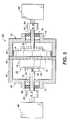
- FIG. 5is a side planar view of the harmonic drive apparatus of FIG. 1 .
- the harmonic friction drive of this inventioncan provide high ratios of speed reduction in a single stage, with very high upper limits to the reduction ratio, all at a reasonable cost, since no gear teeth have to be cut.
- this drivemay be scalable to the MEMS level
- a harmonic friction drive 10in accordance with a preferred embodiment of this invention, comprises a high ratio, speed reduction device.
- the harmonic friction drive 10operates similar to a conventional harmonic gear drive except that it utilizes friction instead of gear teeth to transfer energy from a flexible member 12 to a rigid outer ring member 14 .
- Current high reduction ratio drivesare provided either as multi stage gear drives or single stage harmonic gear drives. Multistage gear drives require a large number of parts and do not lend themselves to miniaturization.
- Harmonic gear drivesare precision devices, which are expensive and limited by gear tooth size, with respect to the maximum reduction ratio which can be obtained and the extent to which they can be miniaturized.
- a harmonic friction drivecomprising the following components.
- the rigid ring 14has a cylindrical inside surface 18 having a given circumference and a given diameter.
- the inside surface 18is free of gear teeth.
- a cup shaped member 20includes a flexible tube portion, which comprises the flexible member 12 , which is joined to a circular disk shaped web portion 22 which forms the bottom of the cup shaped member 20 .
- the thickness of the web portion 22preferably is greater than the thickness of the flexible tube portion 12 so that it can support an input or output shaft as the case may be.
- the shaft 24is an output shaft connected by a coupling 26 and set screw 28 .
- the flexible tube portion 12is nested in the rigid ring 14 .
- the flexible tube portion 12has an outer flexible cylindrical surface 30 whose circumference or undeformed diameter is smaller than the given circumference or diameter of the inside surface 18 of the rigid ring 14 .
- the outer surface 30 of the flexible tube portion 12is also free of gear teeth.
- a wave generator 16is arranged to push the outer surface 30 of the flexible tube portion 12 into frictional engagement against the inside surface 18 of the rigid ring 14 , at two or more zones of contact along the inside surface 18 .
- the wave generator 16rotates the two or more zones of engagement about the inside surface 18 of the ring 14 .
- the difference in circumferences between the outside surface 30 of the flexible tube portion 12 and the inside surface 18 of the ring 14causes the flexible tube portion 12 to rotate a small amount relative to the rigid ring 14 upon each complete revolution of the wave generator 16 , thus providing a large reduction ratio in a single stage.
- Output torque of the drive 10is limited by the coefficient of friction between the outside surface 30 of the flexible tube portion 12 and the inside surface of the rigid ring 14 and the contact force between them.
- the coefficient of friction for this exampleis from about 0.5 to about 0.8.
- the contact force for this exampleis from about 50 pounds to about 300 pounds.
- the coefficient of friction and contact forcecan be readily determined and depend on the torque which is desired from the drive 10 .
- the harmonic wave generator 16forces the flexible tube portion 12 against the outer ring 14 at three points or contact zones 32 .
- any desired number of contact zonescan be used. It is conventional in harmonic gear drives to employ a wave generator of eliptical shape having two contact zones. A similar approach could be employed with this invention if only two contact zones 32 are desired.
- Both fewer and more contact zones 32are possible in accordance with this invention. Fewer than three contact zones 32 are possible, but a one contact zone 32 approach is difficult to implement and two contact zones 32 may not be sufficiently self-centering. More than three contact zones 32 are possible and may be useful for high torque, high ratio designs. Increasing the number of contact zones 32 requires increased distortion of the flexible tube portion 12 . This could result in excessive fatigue for low ratio designs. The greater the number of contact zones 32 the greater the output torque generated by the drive 10 . In the exemplary drive 10 shown in the figures there are three contact zones 32 .
- the input shaft 34is connected by conventional means, such as for example a press fit at one of its ends (not shown), into a central hole 35 of the “Y” shaped yoke or support member 36 of the wave generator.
- the shaft 34rotates the wave generator 16 to cause the contact points or zones 32 to rotate around the inner circumference 18 of the rigid ring 14 .
- the outer circumference 30 of the flexible tube portion 12 of the cup 20is intentionally less than the inner circumference 18 of the outer ring 14 , so that as the contact zones 32 move around the inner circumferential surface 18 of the rigid ring 14 the flexible cup 20 must rotate a small amount to make up for the difference in the respective circumferences.
- the resulting speed reduction provided by the drive 10is determined by the difference in the circumference of the outer surface 30 of the flexible tube portion 12 to the circumference of the inner surface 18 of the ring 14 . Simplified, this becomes the ratio of the difference in the undeformed diameter of the outside surface 30 of the tube portion 12 to the inner diameter of the rigid ring 14 .
- the torque limit of this driveis limited by the friction between the flexible portion 12 and the rigid ring 14 at each zone of contact.
- Drive Torqueis the maximum torque of the wave generator 16 .
- N Zonesis the number of contact points or zones.
- Radial Fis the force imposed by the wave generator assembly 16 at each zone.
- Deform Fis the force required to deform the flexible tube surface 12 .
- Friction Cis the coefficient of friction between the respective surfaces 18 and 30 .
- RRRis the inner radius of the rigid ring 14 .
- the wave drive 16comprises a “Y” shaped frame or support member 36 attached to the input shaft 34 .
- the support member 36carries three roller bearing 37 support frames 38 and three springs 40 and set screws 42 .
- Each of the bearing support frames 38is hinged or pivotally mounted by bolts 39 passing through holes 41 at one of its ends 43 to an arm 44 of the support member 36 .
- the support frames 38can be forced outwardly to increase the radial extension of the bearing 37 against the inner surface 46 the tube portion 12 . This is achieved by the action of a set screw 42 and spring 40 supported by an adjacent arm 44 of the support member 36 acting on the free end 48 of the support frame 38 . This provides the radial contact force which presses the flexible tube portion 12 against the rigid ring 14 .
- the support frames 38generally have an “L” shape with an inclined surface 50 extending between the long 52 and short 54 legs of the frame.
- Bolts 56support bearings 37 for rotation on the support frames 38 and provide the path to apply the contact force to the flexible tube portion 12 with minimal losses.
- the rigid ring 14is held fixed and is bolted to drive 10 support plate 60 . While a square plate 60 is shown it could have any desired shape.
- the drive 10may be supported within a housing 62 made up of two cup shaped halves 64 and 66 which are bolted to each other with the support plate 60 sandwiched therebetween.
- the exterior of the housingmay have any desired shape, square as shown, or cylindrical, etc.
- the ring 14is held fixed in this embodiment it may if desired be rotatable and other elements of the drive 10 may be held fixed.
- the bases 68 and 70 of the respective cup shaped housing halves 62 and 64include centrally located tubular extensions 72 and 74 through which the respective shafts 24 and 34 extend outwardly of the housing 62 .
- the shafts 24 and 34are supported for rotation within the extensions 72 and 74 by respective bearings 76 and 78 and seals 80 and 82 .
- the shafts 24 and 34are connected by couplings 84 and 86 to input or output devices 88 or 90 .
- the input devicecould be a motor or the output of some other device.
- the output devicedepends on the application for which the drive 10 is being used.
- the rigid ring 14 in the exemplary embodimentis held fixed and does not play an input or output role, if desired as will be described hereafter, it need not be fixed and it can be operative as an input or output device.
- the outer surface of the ringcould be cylindrical and it could operate as a roll for engaging a roll connected to an output or input device.
- the outer surface of the ring 12could also support gear teeth, in which case it could act as a gear for engaging a gear connected to an output or input device. Any desired means for using the ring 12 as an input or output connection could be employed if desired.
- a harmonic friction drive 10may be configured to provide reduction gearing or it may function as a speed increaser or as a differential.
- the rigid ring 14can be held fixed as shown, the wave generator 16 can provide the input and the flexible cup 20 can provide the output. The input shaft 34 and output shaft 24 would rotate in opposite directions.
- the wave generator 16can be the input and the rigid ring 14 can be the output. The input shaft 34 and output shaft 24 would rotate in the same direction.
- a harmonic friction drivecan also operate to provide both reduction gearing and act as a differential.
- the wave generator 16is fixed.
- the flexible cup 20comprises the input and the rigid ring 14 comprises the output.
- the input shaft 34 and output shaft 24would rotate in the same direction.
- a wave generatorcan also be used to act as speed increaser gearing/differential.
- the wave generator 16is fixed, the rigid ring 14 provides the input and the flexible cup 20 provides the output and the input and output move in the same direction.
- a harmonic friction drive 10may be used as a differential gearing.
- the wave generator 16is the control input
- the rigid ring 14is the output
- the flexible cupis the drive input.
- Various differential functionscan be obtained by different combinations of speeds and rotations for the three elements 14 , 16 and 20 .
- a harmonic friction drive 10may also be operated as a speed increaser in two different modes.
- the rigid ringIn a first mode the rigid ring is fixed, the flexible cup 20 comprises the input and the wave generator 16 comprises the output.
- the input shaft 24 and the output shaft 34would rotate in opposite directions.
- harmonic friction drives or transmissions 10are particularly useful ways of obtaining significant speed reduction or speed increase and can also be operated in a differential mode.
- respective surface roughnessesshould average between about 20 microns and about 80 microns and preferably from about 30 microns to about 50 microns.
Landscapes
- Engineering & Computer Science (AREA)
- General Engineering & Computer Science (AREA)
- Mechanical Engineering (AREA)
- Retarders (AREA)
Abstract
Description
Claims (6)
Priority Applications (1)
| Application Number | Priority Date | Filing Date | Title |
|---|---|---|---|
| US09/723,689US6439081B1 (en) | 2000-11-28 | 2000-11-28 | Harmonic friction drive |
Applications Claiming Priority (1)
| Application Number | Priority Date | Filing Date | Title |
|---|---|---|---|
| US09/723,689US6439081B1 (en) | 2000-11-28 | 2000-11-28 | Harmonic friction drive |
Publications (1)
| Publication Number | Publication Date |
|---|---|
| US6439081B1true US6439081B1 (en) | 2002-08-27 |
Family
ID=24907276
Family Applications (1)
| Application Number | Title | Priority Date | Filing Date |
|---|---|---|---|
| US09/723,689Expired - LifetimeUS6439081B1 (en) | 2000-11-28 | 2000-11-28 | Harmonic friction drive |
Country Status (1)
| Country | Link |
|---|---|
| US (1) | US6439081B1 (en) |
Cited By (10)
| Publication number | Priority date | Publication date | Assignee | Title |
|---|---|---|---|---|
| US20050262984A1 (en)* | 2004-04-15 | 2005-12-01 | Hetcher Jason D | Miter adjustment assembly for a saw |
| DE102006040020A1 (en)* | 2006-08-25 | 2008-03-20 | Vojacek, Herbert, Prof. Dr.-Ing. | Planetary friction gear with high gear ratio |
| WO2010000302A1 (en)* | 2008-06-30 | 2010-01-07 | Abb Research Ltd | Harmonic friction drive |
| DE102008039942A1 (en)* | 2008-08-27 | 2010-03-25 | Micromotion Gmbh | Gear system i.e. micro gear system, for harmonic drive transmission, has planetary gears and housing part executing housing function and/or bearing function with respect to planet wheel or sun wheel, where wheels are coupled with each other |
| US20100206686A1 (en)* | 2009-02-18 | 2010-08-19 | Xerox Corporation | Gearbox Output Switcher |
| DE112007002580B4 (en)* | 2006-08-25 | 2012-07-05 | Herbert Vojacek | Planetary friction gear with high gear ratio |
| WO2013025331A1 (en) | 2011-08-17 | 2013-02-21 | Genovese Vincent | Fluid driven energy conversion apparatus and method |
| US9394984B2 (en) | 2014-06-09 | 2016-07-19 | Hamilton Sundstrand Corporation | Three point harmonic drive |
| CN110159727A (en)* | 2019-06-19 | 2019-08-23 | 廊坊市钦纵传动科技有限公司 | Economical frictional harmonic speed reducer |
| WO2025140871A1 (en) | 2023-12-28 | 2025-07-03 | SmarAct Holding GmbH | Frictional strain wave gear mechanism, and method |
Citations (14)
| Publication number | Priority date | Publication date | Assignee | Title |
|---|---|---|---|---|
| US3139770A (en)* | 1962-08-14 | 1964-07-07 | United Shoe Machinery Corp | Drive mechanism including self-compensating wave generator |
| US3304809A (en)* | 1964-12-18 | 1967-02-21 | Gen Precision Inc | Torque transmission device |
| US3877259A (en)* | 1973-03-27 | 1975-04-15 | Illinois Tool Works | Shaft coupler |
| US4237751A (en)* | 1978-08-11 | 1980-12-09 | Davis Roland O | Motion transmitting device |
| US4557153A (en)* | 1983-06-13 | 1985-12-10 | Air Monitor Corporation | Harmonic screw actuator |
| US4625582A (en)* | 1983-12-29 | 1986-12-02 | S. Soga & Co. | Harmonic drive apparatus |
| US5269202A (en) | 1991-05-20 | 1993-12-14 | Harmonic Drive Systems, Inc. | Cup-type harmonic drive having a short, flexible cup member |
| US5337638A (en)* | 1993-02-11 | 1994-08-16 | Micro Motors, Inc. | Torque control ratchet wrench |
| US5775178A (en) | 1995-09-29 | 1998-07-07 | Harmonic Drive Systems, Inc. | Wave gear device |
| US5850765A (en) | 1995-05-19 | 1998-12-22 | Harmonic Drive Systems, Inc. | Flat wave gear drive |
| US5906142A (en) | 1997-09-11 | 1999-05-25 | Harmonic Drive Systems, Inc. | Wave gear drive |
| US6065362A (en) | 1996-02-15 | 2000-05-23 | Harmonic Drive Systems, Inc. | Sealed-type wave gear device |
| US6082222A (en) | 1997-10-27 | 2000-07-04 | Harmonic Drive Systems, Inc. | Rigid internal gear of a wave gear drive |
| US6119553A (en) | 1997-12-02 | 2000-09-19 | Harmonic Drive Systems, Inc. | Rotation transmitting device |
- 2000
- 2000-11-28USUS09/723,689patent/US6439081B1/ennot_activeExpired - Lifetime
Patent Citations (14)
| Publication number | Priority date | Publication date | Assignee | Title |
|---|---|---|---|---|
| US3139770A (en)* | 1962-08-14 | 1964-07-07 | United Shoe Machinery Corp | Drive mechanism including self-compensating wave generator |
| US3304809A (en)* | 1964-12-18 | 1967-02-21 | Gen Precision Inc | Torque transmission device |
| US3877259A (en)* | 1973-03-27 | 1975-04-15 | Illinois Tool Works | Shaft coupler |
| US4237751A (en)* | 1978-08-11 | 1980-12-09 | Davis Roland O | Motion transmitting device |
| US4557153A (en)* | 1983-06-13 | 1985-12-10 | Air Monitor Corporation | Harmonic screw actuator |
| US4625582A (en)* | 1983-12-29 | 1986-12-02 | S. Soga & Co. | Harmonic drive apparatus |
| US5269202A (en) | 1991-05-20 | 1993-12-14 | Harmonic Drive Systems, Inc. | Cup-type harmonic drive having a short, flexible cup member |
| US5337638A (en)* | 1993-02-11 | 1994-08-16 | Micro Motors, Inc. | Torque control ratchet wrench |
| US5850765A (en) | 1995-05-19 | 1998-12-22 | Harmonic Drive Systems, Inc. | Flat wave gear drive |
| US5775178A (en) | 1995-09-29 | 1998-07-07 | Harmonic Drive Systems, Inc. | Wave gear device |
| US6065362A (en) | 1996-02-15 | 2000-05-23 | Harmonic Drive Systems, Inc. | Sealed-type wave gear device |
| US5906142A (en) | 1997-09-11 | 1999-05-25 | Harmonic Drive Systems, Inc. | Wave gear drive |
| US6082222A (en) | 1997-10-27 | 2000-07-04 | Harmonic Drive Systems, Inc. | Rigid internal gear of a wave gear drive |
| US6119553A (en) | 1997-12-02 | 2000-09-19 | Harmonic Drive Systems, Inc. | Rotation transmitting device |
Non-Patent Citations (1)
| Title |
|---|
| Harmonic Drive Gearing, HDUC Mini Series Component Set and Unit, 13 Pages. |
Cited By (14)
| Publication number | Priority date | Publication date | Assignee | Title |
|---|---|---|---|---|
| US7798041B2 (en) | 2004-04-15 | 2010-09-21 | Milwaukee Electric Tool Corporation | Miter adjustment assembly for a saw |
| US20060162523A1 (en)* | 2004-04-15 | 2006-07-27 | Milwaukee Electric Tool Corporation | Miter adjustment assembly for a saw |
| US20050262984A1 (en)* | 2004-04-15 | 2005-12-01 | Hetcher Jason D | Miter adjustment assembly for a saw |
| DE102006040020A1 (en)* | 2006-08-25 | 2008-03-20 | Vojacek, Herbert, Prof. Dr.-Ing. | Planetary friction gear with high gear ratio |
| DE112007002580B4 (en)* | 2006-08-25 | 2012-07-05 | Herbert Vojacek | Planetary friction gear with high gear ratio |
| WO2010000302A1 (en)* | 2008-06-30 | 2010-01-07 | Abb Research Ltd | Harmonic friction drive |
| DE102008039942B4 (en)* | 2008-08-27 | 2011-02-10 | Micromotion Gmbh | Planetary gear |
| DE102008039942A1 (en)* | 2008-08-27 | 2010-03-25 | Micromotion Gmbh | Gear system i.e. micro gear system, for harmonic drive transmission, has planetary gears and housing part executing housing function and/or bearing function with respect to planet wheel or sun wheel, where wheels are coupled with each other |
| US20100206686A1 (en)* | 2009-02-18 | 2010-08-19 | Xerox Corporation | Gearbox Output Switcher |
| US8534151B2 (en) | 2009-02-18 | 2013-09-17 | Xerox Corporation | Gearbox output switcher |
| WO2013025331A1 (en) | 2011-08-17 | 2013-02-21 | Genovese Vincent | Fluid driven energy conversion apparatus and method |
| US9394984B2 (en) | 2014-06-09 | 2016-07-19 | Hamilton Sundstrand Corporation | Three point harmonic drive |
| CN110159727A (en)* | 2019-06-19 | 2019-08-23 | 廊坊市钦纵传动科技有限公司 | Economical frictional harmonic speed reducer |
| WO2025140871A1 (en) | 2023-12-28 | 2025-07-03 | SmarAct Holding GmbH | Frictional strain wave gear mechanism, and method |
Similar Documents
| Publication | Publication Date | Title |
|---|---|---|
| JP4787753B2 (en) | Drive unit with reduction gear | |
| US6439081B1 (en) | Harmonic friction drive | |
| EP0719959A1 (en) | Speed reducer | |
| US9574630B2 (en) | Electric linear motion actuator and electric disk brake system | |
| WO2012036033A1 (en) | Planetary gear device | |
| JPH06241285A (en) | Friction gearing type wave motion device | |
| CN111609054B (en) | A clutch structure and control box | |
| JP4444395B2 (en) | Vibration wave drive | |
| JP4301712B2 (en) | Differential friction roller speed reducer | |
| EP1709348B1 (en) | A planetary gear | |
| JP2001008472A5 (en) | ||
| JP2001323971A (en) | Holding structure for internal gear | |
| JP4574731B2 (en) | Vibration wave drive | |
| JP3632358B2 (en) | Friction roller type transmission assembly method | |
| JP4558534B2 (en) | transmission | |
| JP6541055B2 (en) | Traction power transmission | |
| JPH08184359A (en) | Traction drive transmission | |
| CN102308119B (en) | Power transmission device | |
| JP2008309327A (en) | Friction type planetary power transmission device | |
| JP4576263B2 (en) | Traction drive device | |
| JP4759489B2 (en) | Non-contact power transmission device | |
| CN104653753B (en) | Power transmission apparatus for vehicle | |
| CN117697811A (en) | Rotary variable stiffness driver based on cam-arc plate spring mechanism | |
| JP2002081518A (en) | Friction roller type transmission | |
| WO2019119288A1 (en) | Frictional cycloidal drive |
Legal Events
| Date | Code | Title | Description |
|---|---|---|---|
| AS | Assignment | Owner name:XEROX CORPORATION, CONNECTICUT Free format text:ASSIGNMENT OF ASSIGNORS INTEREST;ASSIGNOR:DUFF, DAVID G.;REEL/FRAME:011313/0508 Effective date:20001127 | |
| AS | Assignment | Owner name:BANK ONE, NA, AS ADMINISTRATIVE AGENT, ILLINOIS Free format text:SECURITY AGREEMENT;ASSIGNOR:XEROX CORPORATION;REEL/FRAME:013111/0001 Effective date:20020621 Owner name:BANK ONE, NA, AS ADMINISTRATIVE AGENT,ILLINOIS Free format text:SECURITY AGREEMENT;ASSIGNOR:XEROX CORPORATION;REEL/FRAME:013111/0001 Effective date:20020621 | |
| STCF | Information on status: patent grant | Free format text:PATENTED CASE | |
| AS | Assignment | Owner name:JPMORGAN CHASE BANK, AS COLLATERAL AGENT, TEXAS Free format text:SECURITY AGREEMENT;ASSIGNOR:XEROX CORPORATION;REEL/FRAME:015134/0476 Effective date:20030625 Owner name:JPMORGAN CHASE BANK, AS COLLATERAL AGENT,TEXAS Free format text:SECURITY AGREEMENT;ASSIGNOR:XEROX CORPORATION;REEL/FRAME:015134/0476 Effective date:20030625 | |
| FPAY | Fee payment | Year of fee payment:4 | |
| CC | Certificate of correction | ||
| AS | Assignment | Owner name:DARPA, VIRGINIA Free format text:CONFIRMATORY LICENSE;ASSIGNOR:XEROX CORPORATION;REEL/FRAME:020723/0793 Effective date:20080318 | |
| FPAY | Fee payment | Year of fee payment:8 | |
| FPAY | Fee payment | Year of fee payment:12 | |
| AS | Assignment | Owner name:XEROX CORPORATION, CONNECTICUT Free format text:RELEASE BY SECURED PARTY;ASSIGNOR:JPMORGAN CHASE BANK, N.A. AS SUCCESSOR-IN-INTEREST ADMINISTRATIVE AGENT AND COLLATERAL AGENT TO BANK ONE, N.A.;REEL/FRAME:061388/0388 Effective date:20220822 Owner name:XEROX CORPORATION, CONNECTICUT Free format text:RELEASE BY SECURED PARTY;ASSIGNOR:JPMORGAN CHASE BANK, N.A. AS SUCCESSOR-IN-INTEREST ADMINISTRATIVE AGENT AND COLLATERAL AGENT TO JPMORGAN CHASE BANK;REEL/FRAME:066728/0193 Effective date:20220822 |