US6438503B1 - Estimation of device temperature - Google Patents
Estimation of device temperatureDownload PDFInfo
- Publication number
- US6438503B1 US6438503B1US09/307,619US30761999AUS6438503B1US 6438503 B1US6438503 B1US 6438503B1US 30761999 AUS30761999 AUS 30761999AUS 6438503 B1US6438503 B1US 6438503B1
- Authority
- US
- United States
- Prior art keywords
- time delay
- signal
- time
- value
- operating temperature
- Prior art date
- Legal status (The legal status is an assumption and is not a legal conclusion. Google has not performed a legal analysis and makes no representation as to the accuracy of the status listed.)
- Expired - Lifetime
Links
- 238000000034methodMethods0.000claimsabstractdescription27
- 238000012545processingMethods0.000claimsabstractdescription26
- 230000001934delayEffects0.000claimsdescription4
- 230000036962time dependentEffects0.000claims10
- 230000000630rising effectEffects0.000description4
- 230000000694effectsEffects0.000description3
- 238000005259measurementMethods0.000description3
- 238000013459approachMethods0.000description2
- 230000000246remedial effectEffects0.000description2
- 208000032368Device malfunctionDiseases0.000description1
- 230000001186cumulative effectEffects0.000description1
- 238000013461designMethods0.000description1
Images


Classifications
- G—PHYSICS
- G01—MEASURING; TESTING
- G01K—MEASURING TEMPERATURE; MEASURING QUANTITY OF HEAT; THERMALLY-SENSITIVE ELEMENTS NOT OTHERWISE PROVIDED FOR
- G01K7/00—Measuring temperature based on the use of electric or magnetic elements directly sensitive to heat ; Power supply therefor, e.g. using thermoelectric elements
- G01K7/42—Circuits effecting compensation of thermal inertia; Circuits for predicting the stationary value of a temperature
Definitions
- This inventionrelates to estimation of device operating temperature in processing a signal, and more particularly to use of indirect methods to estimate such temperature.
- operating temperature for processing of a digital signal by a deviceis constant and within the parameter range(s) assumed in the digital design.
- the operating temperature associated with signal processing by a given devicecan vary with time, depending upon the present circumstances and recent history of operation of the device. If the device temperature varies too much from the assumed idealized value, undesirable device responses, such as device malfunction or operation in an undesirable regime, can occur. This is especially true for device temperature that exceeds a threshold temperature value. Inclusion of a system that directly measures such operating temperature is an attractive spectre but is likely to result in an external measure that is too complex, too expensive or too slow acting to fulfill the original function(s) of the device.
- this approachshould be capable of estimating whether the associated device temperature is above or below a threshold value (yes/no) and should be capable of providing a more precise numerical estimate of the associated device temperature, where such estimate is needed.
- the inventionprovides a system and method for indirectly estimating the operating temperature associated with processing of a digital signal by a digital device.
- the inventionmonitors device time delay to indirectly estimate the device operating temperature, by comparing the time delay of a signal processed by a sample device, such as a gate, with an acceptable time delay for the sample device.
- Device operating temperature Ttends to rise monotonically and continuously with increasing device time delay ⁇ t d , although the quantitative details will vary from one type of device to another.
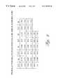
- FIGS. 1 and 2are a representative graphical view and tabular view of a relationship between device operating temperature and a device time delay factor for signal processing.
- FIGS. 3 and 4are schematic views of two embodiment of systems for practicing the invention.
- FIG. 5is a flow chart illustrating a general procedure for practicing the invention.
- FIG. 1is a representative graphical view of a relationship between device operating temperature T and a time delay proportionality factor K t associated with processing of a digital signal by that device.
- K t and Tare approximately linear but may include a non-linear component as shown.
- This relationship between device temperature T and time delay factor K tis approximately the same for all devices of a given kind and with given device parameters but may vary statistically by a relatively small amount from one device to another of the given kind.
- the time delay factor K tis estimated by dividing an observed signal processing time delay ⁇ t d for a given device at a given temperature T by a reference time delay ⁇ t d0 :
- N1 in the time delay factor K t , where the a n are selected polynomial coefficients and the parameter K t0 has a selected value.
- N1 in the time delay factor K t , where the a n are selected polynomial coefficients and the parameter K t0 has a selected value.
- FIG. 3is a schematic view of one embodiment of apparatus that can be used to estimate associated time delay of a device, such as a D-type flipflop and to thereby obtain an estimate of the operating temperature T of this device.
- CLKsingle clock pulse
- w′ ⁇ w ( ⁇ 0)is a determinable time delay for a signal to pass through, and become inverted by, the signal inverter 13 .
- This processis repeated at each of a truncated sequence of D flipflops 11 -n.
- the input signal B(t)is also received at an input terminal of a first time delay module 21 - 1 , having an associated time delay ⁇ t( 0 ) that is to be determined.
- the effective pulse width w′ for the input signal B(t)is substantially greater than a nominal time delay ⁇ t( 1 ) for the first time delay module 21 - 1 .
- the output signal from the first time delay module 21 - 1is sequentially received at an input terminal of a second time delay module 21 - 2 and at a first input terminal of the second D flipflop 11 - 2 .
- the output signal from the second time delay module 21 - 2is received at an input terminal of a third time delay module 21 - 3 and at a first input terminal of a third D flipflop 21 - 3 .
- time delay ⁇ t( 1 )satisfies
- one or more refinementscan be introduced, if desired, to obtain a closer estimate of the time delay ⁇ t( 1 ) associated with the device 21 - 1 .
- the input signal B(t)is a negative pulse of width w
- the net effectis the same as in FIG.
- Estimation of the time delay ⁇ t( 1 ) for one of the time delay modules 21 -mproceeds as before, using the relations (5), (6) and (7) and the relationship between time delay module temperature T and device time delay ⁇ t( 1 ).
- a selected input signalis received by a first sub-system, which includes the target device whose time delay is to be estimated, and by a second sub-system that produces a comparison signal.
- the input signalis processed by the first and second sub-systems to produce first and second sub-system output signals.
- the first and second sub-system output signalsare compared to estimate a time delay ⁇ t d for the target device.
- the systemestimates time delay for one or more of an array of substantially identical devices or sub-systems by issuing a pulse or other signal with a selected, and preferably distinguishing, shape and estimating the maximum and (optional) minimum time bounds for signal processing time delay for a representative device. It is preferable to perform the time delay measurements several times and to determine an average time delay from these measurements. Optionally, one or more statistical outliers can be deleted from the data, if the remaining time delay values are consistent with each other. A functional relationship, such as shown in FIG. 1, can then be used to estimate device temperature. Estimation of device time delay and of device temperature can be performed in software or, less preferably, in hardware.
- the signal shapes used for the multiple measurements of average time delaycan be the same shape.
- two or more different signal shapes or shape parameterscan be used for the multiple signals, consistent with use of digital signals, in order to determine whether signal shape has any consistent effect on the estimated time delay for a given device.
- Two such shape parametersare the pulse width and the distance between the leading edge of two consecutive pulses.
Landscapes
- Physics & Mathematics (AREA)
- General Physics & Mathematics (AREA)
- Feedback Control In General (AREA)
Abstract
Description


Claims (14)
Priority Applications (1)
| Application Number | Priority Date | Filing Date | Title |
|---|---|---|---|
| US09/307,619US6438503B1 (en) | 1999-05-07 | 1999-05-07 | Estimation of device temperature |
Applications Claiming Priority (1)
| Application Number | Priority Date | Filing Date | Title |
|---|---|---|---|
| US09/307,619US6438503B1 (en) | 1999-05-07 | 1999-05-07 | Estimation of device temperature |
Publications (1)
| Publication Number | Publication Date |
|---|---|
| US6438503B1true US6438503B1 (en) | 2002-08-20 |
Family
ID=23190512
Family Applications (1)
| Application Number | Title | Priority Date | Filing Date |
|---|---|---|---|
| US09/307,619Expired - LifetimeUS6438503B1 (en) | 1999-05-07 | 1999-05-07 | Estimation of device temperature |
Country Status (1)
| Country | Link |
|---|---|
| US (1) | US6438503B1 (en) |
Cited By (4)
| Publication number | Priority date | Publication date | Assignee | Title |
|---|---|---|---|---|
| US20060013281A1 (en)* | 2004-07-16 | 2006-01-19 | International Business Machines Corporation | Method and system for real-time estimation and prediction of the thermal state of a microprocessor unit |
| US20070005290A1 (en)* | 2005-06-30 | 2007-01-04 | International Business Machines Corporation | Method and apparatus for monitoring integrated circuit temperature through deterministic path delays |
| US20080039981A1 (en)* | 2006-08-10 | 2008-02-14 | David Wyatt | Temperature sampling in electronic devices |
| US20080040408A1 (en)* | 2006-08-10 | 2008-02-14 | David Wyatt | Temperature sampling in electronic devices |
Citations (6)
| Publication number | Priority date | Publication date | Assignee | Title |
|---|---|---|---|---|
| US5014226A (en)* | 1988-09-29 | 1991-05-07 | Lsi Logic Corporation | Method and apparatus for predicting the metastable behavior of logic circuits |
| US5274568A (en)* | 1990-12-05 | 1993-12-28 | Ncr Corporation | Method of estimating logic cell delay time |
| US5838578A (en)* | 1993-09-21 | 1998-11-17 | Intel Corporation | Method and apparatus for programmable thermal sensor for an integrated circuit |
| US5890100A (en)* | 1997-08-19 | 1999-03-30 | Advanced Micro Devices, Inc. | Chip temperature monitor using delay lines |
| US5943206A (en)* | 1997-08-19 | 1999-08-24 | Advanced Micro Devices, Inc. | Chip temperature protection using delay lines |
| US6090152A (en)* | 1997-03-20 | 2000-07-18 | International Business Machines Corporation | Method and system for using voltage and temperature adders to account for variations in operating conditions during timing simulation |
- 1999
- 1999-05-07USUS09/307,619patent/US6438503B1/ennot_activeExpired - Lifetime
Patent Citations (6)
| Publication number | Priority date | Publication date | Assignee | Title |
|---|---|---|---|---|
| US5014226A (en)* | 1988-09-29 | 1991-05-07 | Lsi Logic Corporation | Method and apparatus for predicting the metastable behavior of logic circuits |
| US5274568A (en)* | 1990-12-05 | 1993-12-28 | Ncr Corporation | Method of estimating logic cell delay time |
| US5838578A (en)* | 1993-09-21 | 1998-11-17 | Intel Corporation | Method and apparatus for programmable thermal sensor for an integrated circuit |
| US6090152A (en)* | 1997-03-20 | 2000-07-18 | International Business Machines Corporation | Method and system for using voltage and temperature adders to account for variations in operating conditions during timing simulation |
| US5890100A (en)* | 1997-08-19 | 1999-03-30 | Advanced Micro Devices, Inc. | Chip temperature monitor using delay lines |
| US5943206A (en)* | 1997-08-19 | 1999-08-24 | Advanced Micro Devices, Inc. | Chip temperature protection using delay lines |
Cited By (15)
| Publication number | Priority date | Publication date | Assignee | Title |
|---|---|---|---|---|
| US7748895B2 (en) | 2004-07-16 | 2010-07-06 | International Business Machines Corporation | Method and system for real-time estimation and prediction of the thermal state of a microprocessor unit |
| US20080215283A1 (en)* | 2004-07-16 | 2008-09-04 | International Business Machines Corporation | Method and system for real-time estimation and prediction of the thermal state of a microprocessor unit |
| US8235593B2 (en) | 2004-07-16 | 2012-08-07 | International Business Machines Corporation | Method and system for real-time estimation and prediction of the thermal state of a microprocessor unit |
| US8096705B2 (en) | 2004-07-16 | 2012-01-17 | International Business Machines Corporation | Method and system for real-time estimation and prediction of the thermal state of a microprocessor unit |
| US20100274522A1 (en)* | 2004-07-16 | 2010-10-28 | International Business Machines Corporation | Method and System for Real-Time Estimation and Prediction of the Thermal State of a Microprocessor Unit |
| US20080059111A1 (en)* | 2004-07-16 | 2008-03-06 | Sri-Jayantha Sri M | Method and system for real-time estimation and prediction of the thermal state of a microprocessor unit |
| US7695188B2 (en) | 2004-07-16 | 2010-04-13 | International Business Machines Corporation | Method and system for real-time estimation and prediction of the thermal state of a microprocessor unit |
| US20100262399A1 (en)* | 2004-07-16 | 2010-10-14 | International Business Machines Corporation | Method and system for real-time estimation and prediction of the thermal state of a microprocessor unit |
| US7347621B2 (en)* | 2004-07-16 | 2008-03-25 | International Business Machines Corporation | Method and system for real-time estimation and prediction of the thermal state of a microprocessor unit |
| US20060013281A1 (en)* | 2004-07-16 | 2006-01-19 | International Business Machines Corporation | Method and system for real-time estimation and prediction of the thermal state of a microprocessor unit |
| US20070005290A1 (en)* | 2005-06-30 | 2007-01-04 | International Business Machines Corporation | Method and apparatus for monitoring integrated circuit temperature through deterministic path delays |
| US7275011B2 (en) | 2005-06-30 | 2007-09-25 | International Business Machines Corporation | Method and apparatus for monitoring integrated circuit temperature through deterministic path delays |
| US20080040408A1 (en)* | 2006-08-10 | 2008-02-14 | David Wyatt | Temperature sampling in electronic devices |
| US7844876B2 (en)* | 2006-08-10 | 2010-11-30 | Intel Corporation | Temperature sampling in electronic devices |
| US20080039981A1 (en)* | 2006-08-10 | 2008-02-14 | David Wyatt | Temperature sampling in electronic devices |
Similar Documents
| Publication | Publication Date | Title |
|---|---|---|
| EP3913885A1 (en) | Anomaly detection method and program | |
| US8086976B2 (en) | Methods for statistical slew propagation during block-based statistical static timing analysis | |
| Nadarajah et al. | The beta Gumbel distribution | |
| Hjort et al. | Tests for constancy of model parameters over time | |
| EP1643332A2 (en) | Hybrid model based fault detection and isolation system | |
| US20040267409A1 (en) | Method and apparatus for memory bandwidth thermal budgetting | |
| KR20090116726A (en) | Methods and systems for evaluating statistical sensitivity credit in path-based hybrid multi-corner static timing analysis | |
| Whitt | Fitting birth-and-death queueing models to data | |
| CN104217091A (en) | Website page view prediction method based on historical tendency weights | |
| US6587999B1 (en) | Modeling delays for small nets in an integrated circuit design | |
| US6438503B1 (en) | Estimation of device temperature | |
| Takhedmit et al. | A parametric uncertainty analysis method for queues with vacations | |
| Kempa | On transient queue-size distribution in the batch arrival system with the N-policy and setup times | |
| CN114282463A (en) | Lifetime prediction method, device and computer readable storage medium of integrated circuit | |
| Browne et al. | The gated infinite-server queue: Uniform service times | |
| US8214557B2 (en) | Measuring direct memory access throughput | |
| Matalytski | Analysis and forecasting of expected incomes in Markov networks with bounded waiting time for the claims | |
| Zijal et al. | Discrete Deterministic and Stochastic Petri Nets. | |
| US20040019450A1 (en) | Method for determining the critical path of an integrated circuit | |
| US7590063B2 (en) | Real-time estimation of event-driven traffic latency distributions when layered on static schedules | |
| US20020077793A1 (en) | System and method for automatically determining an overall risk resulting from a plurality of independent risk factors | |
| Madan et al. | Time-dependent and steady state solution of an M [x]/(G)/1 queueing system with server's long and short vacations | |
| CN112148550B (en) | Method, apparatus and computer program product for managing services | |
| Jack Chen et al. | Density estimation from correlated data | |
| Chen | A stopping rule using the quasi-independent sequence |
Legal Events
| Date | Code | Title | Description |
|---|---|---|---|
| AS | Assignment | Owner name:OAK TECHNOLOGY, INC., CALIFORNIA Free format text:ASSIGNMENT OF ASSIGNORS INTEREST;ASSIGNOR:CHIANG, KEVIN;REEL/FRAME:009956/0551 Effective date:19990506 | |
| STCF | Information on status: patent grant | Free format text:PATENTED CASE | |
| AS | Assignment | Owner name:SUNPLUS TECHNOLOGY CO., LTD., CHINA Free format text:ASSIGNMENT OF ASSIGNORS INTEREST;ASSIGNOR:OAK TECHNOLOGY, INC.;REEL/FRAME:014007/0876 Effective date:20030403 | |
| AS | Assignment | Owner name:OAK TECHNOLOGY, INC., CALIFORNIA Free format text:CHANGE OF NAME;ASSIGNOR:ZINC ACQUISITION CORPORATION;REEL/FRAME:014734/0498 Effective date:20030811 Owner name:ZINC ACQUISITION CORPORATION, CALIFORNIA Free format text:MERGER;ASSIGNOR:OAK TECHNOLOGY, INC.;REEL/FRAME:014734/0491 Effective date:20030811 | |
| FEPP | Fee payment procedure | Free format text:PAYOR NUMBER ASSIGNED (ORIGINAL EVENT CODE: ASPN); ENTITY STATUS OF PATENT OWNER: LARGE ENTITY | |
| FPAY | Fee payment | Year of fee payment:4 | |
| FPAY | Fee payment | Year of fee payment:8 | |
| FPAY | Fee payment | Year of fee payment:12 |