US6437770B1 - Flat-coil actuator having coil embedded in linkage - Google Patents
Flat-coil actuator having coil embedded in linkageDownload PDFInfo
- Publication number
- US6437770B1 US6437770B1US09/237,138US23713899AUS6437770B1US 6437770 B1US6437770 B1US 6437770B1US 23713899 AUS23713899 AUS 23713899AUS 6437770 B1US6437770 B1US 6437770B1
- Authority
- US
- United States
- Prior art keywords
- linkage
- coil
- flat
- coupled
- recited
- Prior art date
- Legal status (The legal status is an assumption and is not a legal conclusion. Google has not performed a legal analysis and makes no representation as to the accuracy of the status listed.)
- Expired - Fee Related
Links
Images


Classifications
- G—PHYSICS
- G06—COMPUTING OR CALCULATING; COUNTING
- G06F—ELECTRIC DIGITAL DATA PROCESSING
- G06F3/00—Input arrangements for transferring data to be processed into a form capable of being handled by the computer; Output arrangements for transferring data from processing unit to output unit, e.g. interface arrangements
- G06F3/01—Input arrangements or combined input and output arrangements for interaction between user and computer
- G06F3/011—Arrangements for interaction with the human body, e.g. for user immersion in virtual reality
- H—ELECTRICITY
- H01—ELECTRIC ELEMENTS
- H01F—MAGNETS; INDUCTANCES; TRANSFORMERS; SELECTION OF MATERIALS FOR THEIR MAGNETIC PROPERTIES
- H01F7/00—Magnets
- H01F7/06—Electromagnets; Actuators including electromagnets
- H01F7/066—Electromagnets with movable winding
- H—ELECTRICITY
- H01—ELECTRIC ELEMENTS
- H01F—MAGNETS; INDUCTANCES; TRANSFORMERS; SELECTION OF MATERIALS FOR THEIR MAGNETIC PROPERTIES
- H01F7/00—Magnets
- H01F7/06—Electromagnets; Actuators including electromagnets
- H01F7/08—Electromagnets; Actuators including electromagnets with armatures
- H01F7/14—Pivoting armatures
- H—ELECTRICITY
- H01—ELECTRIC ELEMENTS
- H01F—MAGNETS; INDUCTANCES; TRANSFORMERS; SELECTION OF MATERIALS FOR THEIR MAGNETIC PROPERTIES
- H01F7/00—Magnets
- H01F7/06—Electromagnets; Actuators including electromagnets
- H01F7/08—Electromagnets; Actuators including electromagnets with armatures
- H01F7/121—Guiding or setting position of armatures, e.g. retaining armatures in their end position
- H01F7/122—Guiding or setting position of armatures, e.g. retaining armatures in their end position by permanent magnets
- H—ELECTRICITY
- H01—ELECTRIC ELEMENTS
- H01F—MAGNETS; INDUCTANCES; TRANSFORMERS; SELECTION OF MATERIALS FOR THEIR MAGNETIC PROPERTIES
- H01F7/00—Magnets
- H01F7/06—Electromagnets; Actuators including electromagnets
- H01F7/08—Electromagnets; Actuators including electromagnets with armatures
- H01F7/16—Rectilinearly-movable armatures
- H01F7/1607—Armatures entering the winding
- H01F7/1615—Armatures or stationary parts of magnetic circuit having permanent magnet
Definitions
- This inventionrelates generally to force output devices, and more particularly to flat-coil actuators for use in force feedback interface devices.
- Actuatorsare used in a variety of devices to output a desired magnitude and direction of force.
- Haptic (“force feedback”) interface devicesare used to interface a human with a host computer and use actuators to output feel sensations to the user to enhance or embellish the user's interaction with an application program running on the host computer.
- Examples of mass-market force feedback interface devicesinclude joysticks and mice.
- a force feedback joystickallows the user to input direction information to a computer by moving the joystick handle in provided degrees of freedom, and uses actuators to output forces in those degrees of freedom to enhance events and interactions occurring in an application program such as a computer game.
- a force feedback mousecan similarly output forces in the degrees of motion of the mouse to assist the user in moving a cursor to icons or windows in a graphical user interface, for example.
- Flat-coil actuatorsare a particular type of actuator which consist of an electric coil (one or more adjacent loops of wire) which is placed in a small air-gap between pairs of opposing-pole permanent magnets such that when electric current is passed through the coil, a force is generated, thereby applying force to and causing motion in an attached linkage.
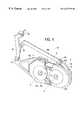
- FIG. 1 aThe structure of a typical rotary flat-coil actuator is shown in FIG. 1 a , which is a top plan view, and FIG. 1 b , which is a side sectional view.
- Actuator linkage (rotor) 1rotates about an axis of rotation 4 to provide motion and a rotary force output at one end 6 of the linkage 1 .
- the end 6can be coupled to another linkage in a mechanism or directly to a manipulandum that is grasped by a user, such as a mouse, joystick handle, stylus, trackball, etc.
- the flat coil 2is provided at the other end of the linkage 1 .
- Stator magnets 3surround the coil 2 , where two magnets are positioned above the coil 2 and two magnets are positioned below the coil 2 .
- Magnet backing irons 5are coupled to the magnets, where one iron is positioned above the coil and one iron is positioned below the coil.
- flat-coil actuatorsare relatively low friction, low backlash (direct drive), low motion range, low force output, and high-speed.
- Flat-coil actuatorsare typically used in applications requiring high-precision, small motions.
- the most common use of flat-coil actuatorsis in computer hard disk drives: a rotary flat-coil actuator controls the position of the magnetic heads moving across the surface of the spinning disk drive platter(s).
- flat-coil actuatorscan be used to drive one or more links in a variety of types of mechanisms and interface applications.
- Some disk drive implementationshave an alternate position sensing technique using an external optical encoder which is connected to the flat-coil actuator by either an extension of the linkage or by some sort of belt drive mechanism.
- this approachagain increases the size of the flat-coil actuator footprint, which is an undesirable characteristic.
- flat-coil actuatorsare inherently limited in performance by the amount of power they can dissipate as heat before the device fails (insulation burns or wire melts). Improvements in the heat dissipation characteristics of a flat-coil actuator would increase actuator performance.
- the present inventiondescribes a flat-coil actuator embedded in a linkage of a force feedback device, and which also includes an embedded sensor. This configuration allows more compact force feedback devices to be implemented.
- a flat-coil actuator of the present inventioncomprises a linkage operative to rotate about an axis.
- the linkagehas two connection points, where one of the connection points is coupled to a ground.
- a flat coilis embedded in the linkage between the connection points.
- a plurality of magnetsare positioned approximately parallel to the flat coil and grounded with respect to the linkage, where a force is produced on the linkage when a current is flowed in the flat coil.
- An embedded position sensorcan be coupled to the linkage; for example, the sensor can include at least a portion of a code disk coupled to the linkage at the axis and an emitter/detector for detecting motion of the portion of said code disk.
- the linkagepreferably surrounds the entire coil in a plane perpendicular to the axis.
- the flat coilpreferably surrounds a non-conductive core that adds mechanical strength to the linkage.
- a force feedback device incorporating the flat-coil actuator of the present inventionincludes a flat-coil actuator as described above, where a force is produced on the linkage when a current is flowed in the flat coil.
- a sensorsuch as an optical encoder is coupled to the linkage for detecting motion of the linkage about the axis.
- a user manipulandum graspable by a useris coupled to a connection point of the linkage such that the force is transmitted to the manipulandum.
- One of the connection points of the linkageis coupled to a ground, and the other of the connection points is coupled to the user manipulandum.
- an intermediate linkageis coupled between the linkage and the user manipulandum.
- a five-bar linkage embodimentprovides two flat-coil actuators and two intermediate linkages rotatably coupled to each other.
- a method of the present invention for using an actuator to provide force feedback to a user of a force feedback deviceincludes flowing a current through a planar coil of a flat-coil actuator included in the force feedback device, where the coil is positioned between first and second ends of a linkage.
- the linkageis rotated about an axis using the current and a magnetic field from at least one magnet positioned adjacent to the coil.
- the rotationoutputs a force at the second end of the linkage, where the force is output to a user manipulandum coupled to the second end of the linkage.
- the rotation of the linkageis sensed with an encoder and a sensor signal is output.
- the sensor signalcan be output to a host computer displaying a graphical environment, where images displayed in the graphical environment are updated based at least in part on the sensor signal, and where the host computer outputs a force feedback signal to the force feedback device so that the force output to the user manipulandum is based at least in part on the force feedback signal.
- the apparatus of the present inventionprovides an integrated flat-coil actuator and mechanical linkage, which reduces the actuator size (footprint) and allows multiple versions of the flat-coil actuator to be mounted in close proximity.
- the embedded coilalso increases the actuator heat dissipation, thereby allowing higher power output.
- the actuatorfurther incorporates embedded position sensing capabilities at no significant increase in footprint size.
- One useful application of the inventions described hereinis in the implementation of small or compact force feedback mechanisms, and is especially applicable to the low-cost mass market of force feedback devices.
- FIGS. 1 a and 1 bare top plan and side sectional views, respectively, of a prior art flat-coil actuator
- FIGS. 2 a and 2 bare top plan and side sectional views, respectively, of a flat-coil actuator and sensor of the present invention
- FIG. 3is a top plan view of a first example embodiment of a mechanical interface using the flat-coil actuator of the present invention
- FIG. 4is a perspective view of a second example embodiment of a mechanical interface using the flat-coil actuator of the present invention.
- FIG. 5is a block diagram of a system including a computer and force feedback interface device including the actuator of the present invention.
- FIG. 2 ais a top plan view and FIG. 2 b is a side sectional view of a transducer 10 of the present invention.
- Transducer 10includes a flat-coil actuator 12 and a sensor 14 .
- Actuator 12includes a linkage (rotor) 16 , a flat coil 18 , a coil core 20 , stator magnets 22 and magnet backing irons 24 .
- Linkage 16is rotatably coupled to a grounded surface by a bearing 26 and may rotate about an axis A.
- the flat coil 18is embedded into the linkage 16 such that the coil is positioned between the two ends of the linkage 16 , i.e. between the two connection points of the linkage, which are the grounded connection point at axis A and the floating connection point at a different point of the linkage (such as end 28 ).
- a portion of the linkage 16surrounds the periphery of the flat coil 18 as shown, where an insulating material can be provided to insulate the linkage material from the coil in those embodiments in which the linkage is made of a conductive material.
- the coil 18also surrounds a core 20 that adds mechanical strength to the actuator mechanism.
- the coil core 20can be made of a nonconductive material, or alternatively, the core can be made of a conductive material, such as metal, with an insulting material provided between the core and the flat coil.
- the coilis shown wound about an approximately trapezoidal shape (in the top plan view), but may be wound about other shapes in other embodiments.
- the stator magnets 22include magnets 22 a and 22 b which abut each other and which are provided on one side of the coil 18 ; and magnets 22 c and 22 d which abut each other and are provided on the opposite side of the coil 18 .
- the magnet backing irons 24provide a flux path for the magnetic flux of the magnets 22 , as is well known to those skilled in the art.
- a backing ironis provided for each pair of magnets 22 a and 22 b , and 22 c and 22 d .
- the backing irons 24 and magnets 22are grounded with respect to the linkage 16 .
- the magnets 22 and backing irons 24are preferably approximately parallel to the plane of the coil 18 , which is the plane perpendicular to the axis of rotation A.
- the actuatoroperates by producing a force on the linkage 16 based on the electromagnetic interaction between a current flowed through the coil and the magnetic fields from magnets 22 .
- the output of force in a flat coil actuatoris well known to those skilled in the art, such in hard disk drives as described in U.S. Pat. No. 5,642,469, incorporated herein by reference.
- the linkage 16is caused to rotate about axis A, thereby producing force in that degree of freedom.
- the flat coil 18is integrated in the mechanism linkage 16 between two ends or connection points of the linkage.
- the actuator 12outputs force at the floating (coil) end 28 of the actuator, as shown by arrow 30 , at a point on the linkage 16 on the same side of the axis of rotation A as the flat coil 18 .
- Another linkage of a mechanism, or a manipulandum itselfcan be coupled to one end or connection point such as connection member 32 at the end 28 , so that the force output by the actuator is transmitted to the other linkage/manipulandum.
- the flat coil 18is thus positioned between the connection points of the linkage 16 , e.g. between the grounded connection point at axis A and the floating connection point at member 32 .
- connection member 32is preferably aligned with an axis B when the linkage 16 is also centered at the axis B, where the axis B intersects the axis of rotation A.
- the member 32(or other connected linkage or member) can also be positioned at other locations on a floating end of the linkage 16 in other embodiments.
- a user manipulandumsuch as a joystick, mouse, stylus, or other grasped object, can be coupled to the floating connection point of the linkage through another mechanism or directly. Examples of multi-member linkage mechanisms are shown with respect to FIGS. 3 and 4.
- the rotary force output by actuator 12can be output in a rotary degree of freedom of a user manipulandum. In other embodiments, the rotary output force can be converted to a linear force and output in a linear degree of freedom of the user manipulandum.
- Sensor 14is used to detect a position of the linkage 16 , and is embedded in the actuator 12 . This means that the sensor 14 reads motion of the actuator rotor. In a force feedback device, since motion of the rotor typically corresponds with motion of the user manipulandum, the sensor effectively reads the position of the manipulandum in a degree of freedom of the manipulandum.
- sensor 14is an optical encoder that includes a code disk 36 , a code disk alignment hub 38 , and an encoder emitter/detector 40 .
- Code disk 36is mounted directly on the rotor 16 and thus rotates with the rotor about axis A.
- Code disk alignment hub 38can be used to align the center of the code disk 36 with the axis A by placing the hub on the shaft of the linkage 16 that rotatably connects the linkage 16 to a ground.
- Emitter/detector 40is grounded with respect to the linkage 16 and code disk 36 and is positioned such that the code disk rotates between the emitter portion 42 and the detector portion 44 (emitter and detector positions can be reversed in alternate embodiments).
- the encoderdetects motion of the code wheel and linkage 16 by detecting a beam emitted by emitter 42 , where the beam is interrupted by portions of the code wheel as the wheel spins, such as spaces between open slots in the edge of the wheel.
- the operation of optical encodersis well known to those skilled in the art.
- Two detectors within detector portion 44can be used to provide quadrature encoding, which allows both the magnitude and direction of motion of the code disk to be sensed. In other embodiments, other types of sensors can be used (Hall effect sensors, potentiometers, etc.).
- the embedded sensorallows the transducer 10 to be of compact design since no separately-placed encoder is required to sense the position of the rotor 16 or the user manipulandum.
- the code disk 36 of the encoderis read by the emitter/detector 40 on the opposite side of the axis of rotation A from the flat coil 18 .
- the emitter/detectoris positioned close to the axis of rotation A to decrease the overall size of the transducer.
- Code disk 36is shown as a circular disk; in other embodiments, only a portion of a circle (an arc) need be used, where the arc moves between the emitter and detector within the allowed movement range of the linkage.
- the encodercan be positioned at other points on the linkage 16 .
- FIG. 3shows an example implementation of a mechanical interface 80 including two opposing rotary transducers of the present invention that include embedded flat coils and embedded position sensors.
- a ground surface 82such as a base, supports a linkage 84 a and a linkage 84 b , which include a flat coil as according to the flat-coil actuator 12 of the present invention.
- Magnets(not shown) are also provided as described above with reference to FIGS. 2 a and 2 b .
- An optical encoder(not shown) is also preferably coupled to each of linkages 84 similar to the embodiment of FIG. 2 .
- the linkages 84 a and 84 bare rotatably coupled to the ground surface 82 and thus may rotate about axes A and B, respectively.
- An intermediate linkage 86 ais rotatably coupled to linkage 84 a at the connection point 88 a
- an intermediate linkage 86 bis rotatably coupled to linkage 84 b at the connection point 88 b .
- the intermediate linkages 86 a and 86 bare rotatably coupled to each other at ends not coupled to the linkages 84 a and 84 b , respectively.
- the intermediate linkages 86 a and 86 bthus may be rotated about axes C and D, respectively, at the connection points 88 in a plane parallel to the plane of rotation of the linkages 84 a and 84 b about axes A and B.
- the connected ends of the intermediate linkagesmay similarly rotate with respect to each other about axis E.
- the mechanism 80is thus a closed-loop 5-bar linkage mechanism, each of the linkages rotatably coupled to two other linkages, and where the flat-coil actuators are embedded in two of the five linkages.
- a user manipulandum 90is coupled at or near the axis E such that the manipulandum may be moved in two planar degrees of freedom.
- Such a user manipulandumcan include a mouse, joystick, stylus, finger contact, sphere, or other object.
- the linkages 84 a and 84 bcan be positioned in other orientations with respect to each other, e.g. the connection points of the linkages 84 at axes A and B can be positioned differently with respect to each other.
- the linkages of the mechanismcan be of different lengths and have different link parameters.
- linkage 86 acan have a longer length than linkage 86 b
- the end of linkage 86 bcan be rotatably coupled to linkage 86 a at a point between the ends of linkage 86 a (see FIG. 4 ).
- Other types of linkage mechanismssuch as open-loop mechanisms, can also be provided.
- more than two flat-coil actuatorscan be provided in a force feedback mechanism.
- a manipulandum having three degrees of freedomcan be provided with force feedback from a different flat-coil actuator of the present invention associated with each degree of freedom.
- FIG. 4is a perspective view of a different embodiment of a mechanical interface 92 that include two opposing rotary actuators of the present invention which are mounted in close proximity for a compact design. Similar to the mechanical interface 80 of FIG. 3, interface 92 includes two actuators 93 a and 93 b of the present invention. The grounded backing irons 94 a and 94 b of the two actuators can be coupled together as shown such that the axes of rotation A and B of the actuators are coupled to ground and positioned closer together rather than apart as shown in FIG. 3 .
- Two linkages 95 a and 95 binclude coils 18 embedded within them and rotate between magnets 22 , and are rotatably coupled to linkages 96 a and 96 b , respectively, at the connection points 97 a and 97 b .
- the floating connection point 97 b of linkage 95 bis positioned differently with respect to the coil/linkage 95 b than the floating connection point of linkage 95 a with respect to coil/linkage 95 a .
- the linkages 96 a and 96 bare rotatably coupled to each other at point 98 , thus forming a closed-loop five bar linkage mechanism similar to the mechanism shown in FIG.
- linkages 95 and 96have different lengths and configurations with respect to each other, i.e. are asymmetrical. Different linkage lengths, coupling points, and orientations can be provided in alternate embodiments.
- a user manipulandum 99can be coupled to the linkage 96 a (or linkage 96 b in other embodiments), and can be a mouse, joystick, stylus, or other grasped object.
- FIG. 5is a block diagram illustrating an architecture of a system 100 incorporating a force feedback interface device that uses the flat-coil actuator design of the present invention.
- System 100includes a force feedback interface device 112 and a host computer 114 .
- Force feedback interface device 112includes a user manipulandum 116 , a mechanical interface 118 , and an electronic interface 120 .
- Mechanical interface 118interfaces mechanical input and output between the user manipulandum 116 and host computer 114 implementing the graphical environment.
- Mechanical interface 118provides one or more degrees of freedom to manipulandum 116 .
- the usermanipulates manipulandum 116 in provided degrees of freedom and the position and/or orientation of the manipulandum is translated using mechanical interface 118 into a form suitable for interpretation by the sensors of the mechanical interface.
- the sensorstrack the movement of the manipulandum and provide suitable electronic signals to electronic interface 120 .
- Electronic interface 120provides position and/or orientation information to host computer 114 .
- host computer 114 and/or electronic interface 120provides force feedback signals or commands to the actuators included in mechanical interface 118 , and the actuators generate forces on members of the mechanical apparatus to provide forces on manipulandum 116 in provided or desired degrees of freedom.
- the userexperiences the forces generated on the manipulandum as realistic simulations of force sensations such as jolts, textures, vibrations, “barrier” forces, springs, dampers, and the like.
- the computer 114can send force feedback signals to the electrical interface 120 and mechanical apparatus 118 to generate collision forces on the manipulandum 116 .
- Electronic interface 120may couple the mechanical apparatus 118 to the host computer 114 .
- Electronic interface 120can be included within a housing of mechanical apparatus 118 , in its own housing, or in host computer 114 . More particularly, electronic interface 120 includes sensor and actuator interfaces that convert electrical signals to appropriate forms usable by mechanical apparatus 118 and host computer 114 , such as amplifiers, digital-to-analog converters, etc.
- Interface 120can also include a microprocessor local to the mechanical interface 118 and separate from any microprocessors in the host computer 114 to control local force feedback independently of the host computer.
- the local microprocessorcan read sensor signals, compute forces, and control the flat-coil actuators to output the computed forces independently of the host computer, as is well known to those skilled in the art.
- the electronic interface 120is coupled to the computer 114 by a bus 124 (or may be directly connected to the computer using a interface card). In other embodiments, signals can be sent to and from interface 120 and computer 114 by wireless transmission/reception.
- the interface 120can serve as an input/output (I/O) device for the computer 114 , and can receive inputs from other input devices or controls that are associated with mechanical interface 118 or manipulandum 116 and can relay those inputs to computer 114 , such as button inputs from a button on manipulandum 116 .
- Host computer 114is preferably a personal computer or workstation, such as a PC compatible computer or Macintosh personal computer, or a SUN or Silicon Graphics workstation.
- the computer 114can operate under the WindowsTM or MSDOS operating system in conformance with an IBM PC AT standard.
- host computer system 114can be one of a variety of home video game systems commonly connected to a television set, a “set top box”, “Internet computer” or the like.
- Host computer 14preferably includes a host microprocessor, random access memory (RAM), read only memory (ROM), input/output (I/O) circuitry, and other components of computers well-known to those skilled in the art.
- RAMrandom access memory
- ROMread only memory
- I/Oinput/output
- Host computer 114implements a host application program with which a user is interacting via mechanical interface apparatus 118 and other peripherals, if appropriate.
- the host application programcan be a video game, medical or other simulation, scientific analysis program, or other application program that utilizes input of manipulandum 116 and outputs force feedback to the manipulandum.
- the host application programchecks for input signals received from electronic interface 120 and sensors of mechanical interface 118 , and outputs force values and commands to be converted into forces on manipulandum 116 .
Landscapes
- Engineering & Computer Science (AREA)
- Physics & Mathematics (AREA)
- Electromagnetism (AREA)
- General Engineering & Computer Science (AREA)
- Theoretical Computer Science (AREA)
- Power Engineering (AREA)
- Human Computer Interaction (AREA)
- General Physics & Mathematics (AREA)
- Position Input By Displaying (AREA)
Abstract
Description
This application claims the benefit of provisional application Ser. No. 60/072,525, filed Jan. 26, 1998 by Steven Venema and Blake Hannaford, entitled “Flat-Coil Actuator Having Actuator Coil and Position Encoder Embedded in Linkage,” which is incorporated herein by reference.
This invention relates generally to force output devices, and more particularly to flat-coil actuators for use in force feedback interface devices.
Actuators are used in a variety of devices to output a desired magnitude and direction of force. Haptic (“force feedback”) interface devices are used to interface a human with a host computer and use actuators to output feel sensations to the user to enhance or embellish the user's interaction with an application program running on the host computer. Examples of mass-market force feedback interface devices include joysticks and mice. A force feedback joystick allows the user to input direction information to a computer by moving the joystick handle in provided degrees of freedom, and uses actuators to output forces in those degrees of freedom to enhance events and interactions occurring in an application program such as a computer game. A force feedback mouse can similarly output forces in the degrees of motion of the mouse to assist the user in moving a cursor to icons or windows in a graphical user interface, for example.
Flat-coil actuators are a particular type of actuator which consist of an electric coil (one or more adjacent loops of wire) which is placed in a small air-gap between pairs of opposing-pole permanent magnets such that when electric current is passed through the coil, a force is generated, thereby applying force to and causing motion in an attached linkage. The structure of a typical rotary flat-coil actuator is shown in FIG. 1a, which is a top plan view, and FIG. 1b, which is a side sectional view. Actuator linkage (rotor)1 rotates about an axis of rotation4 to provide motion and a rotary force output at one end6 of thelinkage 1. In a force feedback interface device, the end6, for example, can be coupled to another linkage in a mechanism or directly to a manipulandum that is grasped by a user, such as a mouse, joystick handle, stylus, trackball, etc. The flat coil2 is provided at the other end of thelinkage 1.Stator magnets 3 surround the coil2, where two magnets are positioned above the coil2 and two magnets are positioned below the coil2.Magnet backing irons 5 are coupled to the magnets, where one iron is positioned above the coil and one iron is positioned below the coil.
In comparison with many other types of electric actuators, flat-coil actuators are relatively low friction, low backlash (direct drive), low motion range, low force output, and high-speed. Flat-coil actuators are typically used in applications requiring high-precision, small motions. The most common use of flat-coil actuators is in computer hard disk drives: a rotary flat-coil actuator controls the position of the magnetic heads moving across the surface of the spinning disk drive platter(s). In haptic or force feedback mechanisms, flat-coil actuators can be used to drive one or more links in a variety of types of mechanisms and interface applications.
Current rotary flat-coil designs for haptic mechanisms based on pre-existing disk-drive flat-coil actuators, such as described in U.S. Pat. No. 5,642,469, have some significant limitations. One limitation is that the large footprint of the actuator precludes the use of multiple flat-coil actuators in close proximity. Multiple adjacent flat-coil actuators would allow more compact haptic mechanisms to be used. Another limitation is that position sensing in disk-drive flat-coil actuators is often performed using a dedicated read-only disk surface which contains factory-written positioning data to be read by the magnetic head for that surface. This approach is unfeasible for haptic mechanisms since no spinning disk surface is available. Some disk drive implementations have an alternate position sensing technique using an external optical encoder which is connected to the flat-coil actuator by either an extension of the linkage or by some sort of belt drive mechanism. However, this approach again increases the size of the flat-coil actuator footprint, which is an undesirable characteristic. Yet another limitation is that flat-coil actuators are inherently limited in performance by the amount of power they can dissipate as heat before the device fails (insulation burns or wire melts). Improvements in the heat dissipation characteristics of a flat-coil actuator would increase actuator performance.
The present invention describes a flat-coil actuator embedded in a linkage of a force feedback device, and which also includes an embedded sensor. This configuration allows more compact force feedback devices to be implemented.
More particularly, a flat-coil actuator of the present invention comprises a linkage operative to rotate about an axis. The linkage has two connection points, where one of the connection points is coupled to a ground. A flat coil is embedded in the linkage between the connection points. A plurality of magnets are positioned approximately parallel to the flat coil and grounded with respect to the linkage, where a force is produced on the linkage when a current is flowed in the flat coil. An embedded position sensor can be coupled to the linkage; for example, the sensor can include at least a portion of a code disk coupled to the linkage at the axis and an emitter/detector for detecting motion of the portion of said code disk. The linkage preferably surrounds the entire coil in a plane perpendicular to the axis. Furthermore, the flat coil preferably surrounds a non-conductive core that adds mechanical strength to the linkage.
A force feedback device incorporating the flat-coil actuator of the present invention includes a flat-coil actuator as described above, where a force is produced on the linkage when a current is flowed in the flat coil. A sensor such as an optical encoder is coupled to the linkage for detecting motion of the linkage about the axis. A user manipulandum graspable by a user is coupled to a connection point of the linkage such that the force is transmitted to the manipulandum. One of the connection points of the linkage is coupled to a ground, and the other of the connection points is coupled to the user manipulandum. In one embodiment, an intermediate linkage is coupled between the linkage and the user manipulandum. A five-bar linkage embodiment provides two flat-coil actuators and two intermediate linkages rotatably coupled to each other.
A method of the present invention for using an actuator to provide force feedback to a user of a force feedback device includes flowing a current through a planar coil of a flat-coil actuator included in the force feedback device, where the coil is positioned between first and second ends of a linkage. The linkage is rotated about an axis using the current and a magnetic field from at least one magnet positioned adjacent to the coil. The rotation outputs a force at the second end of the linkage, where the force is output to a user manipulandum coupled to the second end of the linkage. The rotation of the linkage is sensed with an encoder and a sensor signal is output. The sensor signal can be output to a host computer displaying a graphical environment, where images displayed in the graphical environment are updated based at least in part on the sensor signal, and where the host computer outputs a force feedback signal to the force feedback device so that the force output to the user manipulandum is based at least in part on the force feedback signal.
The apparatus of the present invention provides an integrated flat-coil actuator and mechanical linkage, which reduces the actuator size (footprint) and allows multiple versions of the flat-coil actuator to be mounted in close proximity. The embedded coil also increases the actuator heat dissipation, thereby allowing higher power output. The actuator further incorporates embedded position sensing capabilities at no significant increase in footprint size. One useful application of the inventions described herein is in the implementation of small or compact force feedback mechanisms, and is especially applicable to the low-cost mass market of force feedback devices.
These and other advantages of the present invention will become apparent to those skilled in the art upon a reading of the following specification of the invention and a study of the several figures of the drawing.
FIGS. 1aand1bare top plan and side sectional views, respectively, of a prior art flat-coil actuator;
FIGS. 2aand2bare top plan and side sectional views, respectively, of a flat-coil actuator and sensor of the present invention;
FIG. 3 is a top plan view of a first example embodiment of a mechanical interface using the flat-coil actuator of the present invention;
FIG. 4 is a perspective view of a second example embodiment of a mechanical interface using the flat-coil actuator of the present invention; and
FIG. 5 is a block diagram of a system including a computer and force feedback interface device including the actuator of the present invention.
FIG. 2ais a top plan view and FIG. 2bis a side sectional view of atransducer 10 of the present invention.Transducer 10 includes a flat-coil actuator 12 and asensor 14.Actuator 12 includes a linkage (rotor)16, aflat coil 18, acoil core 20,stator magnets 22 andmagnet backing irons 24.Linkage 16 is rotatably coupled to a grounded surface by abearing 26 and may rotate about an axis A.
Theflat coil 18 is embedded into thelinkage 16 such that the coil is positioned between the two ends of thelinkage 16, i.e. between the two connection points of the linkage, which are the grounded connection point at axis A and the floating connection point at a different point of the linkage (such as end28). A portion of thelinkage 16 surrounds the periphery of theflat coil 18 as shown, where an insulating material can be provided to insulate the linkage material from the coil in those embodiments in which the linkage is made of a conductive material. Thecoil 18 also surrounds a core20 that adds mechanical strength to the actuator mechanism. Thecoil core 20 can be made of a nonconductive material, or alternatively, the core can be made of a conductive material, such as metal, with an insulting material provided between the core and the flat coil. The coil is shown wound about an approximately trapezoidal shape (in the top plan view), but may be wound about other shapes in other embodiments.
Thestator magnets 22 includemagnets coil 18; andmagnets 22cand22dwhich abut each other and are provided on the opposite side of thecoil 18. Themagnet backing irons 24 provide a flux path for the magnetic flux of themagnets 22, as is well known to those skilled in the art. A backing iron is provided for each pair ofmagnets backing irons 24 andmagnets 22 are grounded with respect to thelinkage 16. Themagnets 22 andbacking irons 24 are preferably approximately parallel to the plane of thecoil 18, which is the plane perpendicular to the axis of rotation A.
The actuator operates by producing a force on thelinkage 16 based on the electromagnetic interaction between a current flowed through the coil and the magnetic fields frommagnets 22. The output of force in a flat coil actuator is well known to those skilled in the art, such in hard disk drives as described in U.S. Pat. No. 5,642,469, incorporated herein by reference. Thelinkage 16 is caused to rotate about axis A, thereby producing force in that degree of freedom.
One of the important advantages of the present invention is that theflat coil 18 is integrated in themechanism linkage 16 between two ends or connection points of the linkage. Thus, theactuator 12 outputs force at the floating (coil) end28 of the actuator, as shown byarrow 30, at a point on thelinkage 16 on the same side of the axis of rotation A as theflat coil 18. Another linkage of a mechanism, or a manipulandum itself, can be coupled to one end or connection point such asconnection member 32 at theend 28, so that the force output by the actuator is transmitted to the other linkage/manipulandum. Theflat coil 18 is thus positioned between the connection points of thelinkage 16, e.g. between the grounded connection point at axis A and the floating connection point atmember 32.
The coil embedded in the linkage and output of force atend 28 allows a more compact actuator design in comparison to the prior art actuators as shown in FIGS. 1aand1b. This is because the linkage need not extend away from both sides of the axis of rotation A, thereby saving space on one side of the axis A. This approach reduces the amount of space needed behind the actuator, i.e. a reduced footprint is possible. Furthermore, a compact, embedded sensor may then be placed at the axis A without interference from thelinkage 16. A preferred sensor is described in greater detail below.
As shown in FIG. 2a, theconnection member 32 is preferably aligned with an axis B when thelinkage 16 is also centered at the axis B, where the axis B intersects the axis of rotation A. The member32 (or other connected linkage or member) can also be positioned at other locations on a floating end of thelinkage 16 in other embodiments. A user manipulandum, such as a joystick, mouse, stylus, or other grasped object, can be coupled to the floating connection point of the linkage through another mechanism or directly. Examples of multi-member linkage mechanisms are shown with respect to FIGS. 3 and 4.
In addition, embedding thecoil 18 into thelinkage 16 increases the heat transfer from the coil to the link (in those embodiments in which the linkage is made of a material allowing it to act as a heatsink). This allows the actuator to be used at higher power levels without overheating. Finally, this mounting method gives added strength to the coil-rotor mechanical connection since the coil is completely surrounded by the linkage material in the plane of the coil.
In some embodiments, the rotary force output byactuator 12 can be output in a rotary degree of freedom of a user manipulandum. In other embodiments, the rotary output force can be converted to a linear force and output in a linear degree of freedom of the user manipulandum.
In the preferred embodiment,sensor 14 is an optical encoder that includes acode disk 36, a codedisk alignment hub 38, and an encoder emitter/detector 40.Code disk 36 is mounted directly on therotor 16 and thus rotates with the rotor about axis A. Codedisk alignment hub 38 can be used to align the center of thecode disk 36 with the axis A by placing the hub on the shaft of thelinkage 16 that rotatably connects thelinkage 16 to a ground. Emitter/detector 40 is grounded with respect to thelinkage 16 andcode disk 36 and is positioned such that the code disk rotates between theemitter portion 42 and the detector portion44 (emitter and detector positions can be reversed in alternate embodiments). The encoder detects motion of the code wheel andlinkage 16 by detecting a beam emitted byemitter 42, where the beam is interrupted by portions of the code wheel as the wheel spins, such as spaces between open slots in the edge of the wheel. The operation of optical encoders is well known to those skilled in the art. Two detectors withindetector portion 44 can be used to provide quadrature encoding, which allows both the magnitude and direction of motion of the code disk to be sensed. In other embodiments, other types of sensors can be used (Hall effect sensors, potentiometers, etc.).
The embedded sensor allows thetransducer 10 to be of compact design since no separately-placed encoder is required to sense the position of therotor 16 or the user manipulandum. Thecode disk 36 of the encoder is read by the emitter/detector 40 on the opposite side of the axis of rotation A from theflat coil 18. The emitter/detector is positioned close to the axis of rotation A to decrease the overall size of the transducer.Code disk 36 is shown as a circular disk; in other embodiments, only a portion of a circle (an arc) need be used, where the arc moves between the emitter and detector within the allowed movement range of the linkage. In other embodiments, the encoder can be positioned at other points on thelinkage 16.
The increased compactness of this new rotary flat-coil actuator design allows multiple flat-coil actuators to be mounted within close proximity to each other, a desirable trait for haptic displays. FIG. 3 shows an example implementation of amechanical interface 80 including two opposing rotary transducers of the present invention that include embedded flat coils and embedded position sensors. Aground surface 82, such as a base, supports alinkage 84aand alinkage 84b, which include a flat coil as according to the flat-coil actuator 12 of the present invention. Magnets (not shown) are also provided as described above with reference to FIGS. 2aand2b. An optical encoder (not shown) is also preferably coupled to each of linkages84 similar to the embodiment of FIG.2. Thelinkages ground surface 82 and thus may rotate about axes A and B, respectively. Anintermediate linkage 86ais rotatably coupled tolinkage 84aat the connection point88a, and anintermediate linkage 86bis rotatably coupled tolinkage 84bat the connection point88b. Theintermediate linkages linkages intermediate linkages linkages mechanism 80 is thus a closed-loop 5-bar linkage mechanism, each of the linkages rotatably coupled to two other linkages, and where the flat-coil actuators are embedded in two of the five linkages. Preferably, auser manipulandum 90 is coupled at or near the axis E such that the manipulandum may be moved in two planar degrees of freedom. Such a user manipulandum can include a mouse, joystick, stylus, finger contact, sphere, or other object.
In other embodiments, thelinkages linkage 86acan have a longer length thanlinkage 86b, and the end oflinkage 86bcan be rotatably coupled tolinkage 86aat a point between the ends oflinkage 86a(see FIG.4). Other types of linkage mechanisms, such as open-loop mechanisms, can also be provided. Furthermore, in other embodiments of the present invention, more than two flat-coil actuators can be provided in a force feedback mechanism. For example, a manipulandum having three degrees of freedom can be provided with force feedback from a different flat-coil actuator of the present invention associated with each degree of freedom.
FIG. 4 is a perspective view of a different embodiment of amechanical interface 92 that include two opposing rotary actuators of the present invention which are mounted in close proximity for a compact design. Similar to themechanical interface 80 of FIG. 3,interface 92 includes twoactuators backing irons linkages coils 18 embedded within them and rotate betweenmagnets 22, and are rotatably coupled tolinkages 96aand96b, respectively, at the connection points97aand97b. As an example, the floatingconnection point 97boflinkage 95bis positioned differently with respect to the coil/linkage 95bthan the floating connection point oflinkage 95awith respect to coil/linkage 95a. Thelinkages 96aand96bare rotatably coupled to each other atpoint 98, thus forming a closed-loop five bar linkage mechanism similar to the mechanism shown in FIG. 3; however, thelinkages 95 and96 have different lengths and configurations with respect to each other, i.e. are asymmetrical. Different linkage lengths, coupling points, and orientations can be provided in alternate embodiments. Auser manipulandum 99 can be coupled to the linkage96a(orlinkage 96bin other embodiments), and can be a mouse, joystick, stylus, or other grasped object.
FIG. 5 is a block diagram illustrating an architecture of asystem 100 incorporating a force feedback interface device that uses the flat-coil actuator design of the present invention.System 100 includes a forcefeedback interface device 112 and ahost computer 114. Forcefeedback interface device 112 includes a user manipulandum116, amechanical interface 118, and anelectronic interface 120.
User manipulandum116 used in conjunction with the present invention is physically contacted (e.g. grasped) and manipulated by a user to provide input to thehost computer 114 and to allow the user to experience force feedback output by the system. Images displayed on adisplay screen 122 of thecomputer system 114 can be updated in response to such manipulations. For example, a user can move a mouse116 to correspondingly move a computer generated object, such as a cursor, in a graphical or virtual environment. It will be appreciated that a great number of types of objects can be used as manipulandums with the method and apparatus of the present invention. Such objects may include a mouse, joystick handle, stylus, grip, sphere, medical instrument, steering wheel, screw driver, etc.
Themechanical interface 118 includes the embedded flat-coil actuators as described with reference to FIGS. 2aand2b. The linkages included in the mechanical interface which transmit forces to the manipulandum can take a variety of forms; some examples are shown above with respect to FIGS. 3 and 4.
Theelectronic interface 120 is coupled to thecomputer 114 by a bus124 (or may be directly connected to the computer using a interface card). In other embodiments, signals can be sent to and frominterface 120 andcomputer 114 by wireless transmission/reception. Theinterface 120 can serve as an input/output (I/O) device for thecomputer 114, and can receive inputs from other input devices or controls that are associated withmechanical interface 118 or manipulandum116 and can relay those inputs tocomputer 114, such as button inputs from a button on manipulandum116.
While this invention has been described in terms of several preferred embodiments, there are alterations, modifications, and permutations thereof which fall within the scope of this invention. It should also be noted that the embodiments described above can be combined in various ways in a particular implementation. Furthermore, certain terminology has been used for the purposes of descriptive clarity, and not to limit the present invention. It is therefore intended that the following appended claims include such alterations, modifications, and permutations as fall within the true spirit and scope of the present invention.
Claims (20)
1. A flat-coil actuator comprising:
a linkage operative to rotate about an axis, said linkage having two connection points, wherein one of said connection points is coupled to a ground;
a flat coil embedded in said linkage, said flat coil being positioned between said connection points; and
a plurality of magnets positioned approximately parallel to said flat coil and grounded with respect to said linkage, wherein a first one or more magnets is positioned on a first side of said flat coil, and wherein a second one or more magnets is positioned on a second side of said flat coil such that said coil is oriented in a plane positioned between a plane of said first magnets and a plane of said second magnets, wherein a force is produced on said linkage when a current is flowed in said flat coil.
2. A flat-coil actuator as recited inclaim 1 further comprising an embedded position sensor coupled to said linkage.
3. A flat-coil actuator as recited inclaim 2 wherein said sensor includes at least a portion of a code disk coupled to said linkage at said axis and an emitter/detector for detecting motion of said portion of said code disk.
4. A flat-coil transducer as recited inclaim 1 wherein said linkage is rotatably coupled to a ground at one of said connection points and to another linkage at the other of said connection points.
5. A flat-coil transducer as recited inclaim 1 wherein said flat coil surrounds a core that adds mechanical strength to said linkage.
6. A flat-coil transducer as recited inclaim 1 wherein each of said magnets is coupled to a backing iron.
7. A flat-coil transducer as recited inclaim 1 wherein said linkage is coupled to a user manipulandum physically contacted by a user.
8. A force feedback interface device including an improved flat-coil actuator, the force feedback interface device comprising:
a flat-coil actuator including:
a linkage operative to rotate about an axis and having two connection points;
a flat coil embedded in said linkage, said flat coil being positioned between said two connection points of said linkage; and
a plurality of magnets positioned approximately parallel to said flat coil and grounded with respect to said linkage, wherein a force is produced on said linkage when a current is flowed in said flat coil;
a sensor coupled to said linkage for detecting motion of said linkage about said axis; and
a user manipulandum graspable by a user and coupled to one of said connection point of said linkage such that said force is transmitted to said user manipulandum.
9. A force feedback interface device as recited inclaim 8 wherein one of said connection points of said linkage is coupled to a ground, and the other of said connection points is coupled to said user manipulandum.
10. A force feedback interface device as recited inclaim 8 further comprising an intermediate linkage coupled between said linkage and said user manipulandum.
11. A force feedback interface device as recited inclaim 10 wherein said flat-coil actuator is a first flat-coil actuator, and further comprising a second flat-coil actuator, wherein said user manipulandum is coupled to both said first and second flat-coil actuators.
12. A force feedback interface device as recited inclaim 11 wherein said intermediate linkage is a first intermediate linkage, and further comprising a second intermediate linkage coupled between said second flat-coil actuator and said user manipulandum, wherein said first and second intermediate linkages are rotatably coupled to each other.
13. A force feedback interface device as recited inclaim 12 wherein said flat-coil actuators and said intermediate linkages form a closed-loop five-bar linkage mechanism having linkages rotatably coupled to each other.
14. A force feedback interface device as recited inclaim 8 wherein said flat coil is embedded in said end of said linkage such that a portion of said linkage entirely surrounds said coil in a plane perpendicular to said axis.
15. A force feedback interface device as recited inclaim 8 wherein said sensor is an optical encoder including a code disk coupled to said linkage at said axis and a emitter/detector for detecting motion of said code disk.
16. A force feedback interface device as recited inclaim 15 wherein said code disk is positioned between an emitter and a detector of said emitter/detector.
17. A method for using an actuator to provide force feedback to a user of a force feedback device, the method comprising:
flowing a current through a planar coil of a flat-coil actuator included in said force feedback device, said coil positioned between first and second connection points of a member;
rotating said member about an axis using said current and a magnetic field from at least one magnet positioned adjacent to said coil, wherein said rotation outputs a force at said second connection point of said member, wherein said force is output to a user manipulandum coupled to said second connection point of said member; and
sensing said rotation of said member with an encoder and outputting a sensor signal representative of said rotation of said member.
18. A method as recited inclaim 17 wherein said encoder includes a code disk coupled to said rotor at said axis and an emitter/detector for detecting motion of said code disk, wherein said code disk is positioned between an emitter and a detector of said emitter/detector.
19. A method as recited inclaim 17 wherein said sensor signal is output to a host computer including a display screen, wherein images displayed on said display screen are updated at least in part based on said sensor signal.
20. A method as recited inclaim 17 wherein said sensor signal is output to a host computer displaying a graphical environment, wherein images displayed in said graphical environment are updated based at least in part on said sensor signal, and wherein said host computer outputs a force feedback signal to said force feedback device, wherein said force output to said user manipulandum is based at least in part on said force feedback signal.
Priority Applications (1)
| Application Number | Priority Date | Filing Date | Title |
|---|---|---|---|
| US09/237,138US6437770B1 (en) | 1998-01-26 | 1999-01-25 | Flat-coil actuator having coil embedded in linkage |
Applications Claiming Priority (2)
| Application Number | Priority Date | Filing Date | Title |
|---|---|---|---|
| US7252598P | 1998-01-26 | 1998-01-26 | |
| US09/237,138US6437770B1 (en) | 1998-01-26 | 1999-01-25 | Flat-coil actuator having coil embedded in linkage |
Publications (1)
| Publication Number | Publication Date |
|---|---|
| US6437770B1true US6437770B1 (en) | 2002-08-20 |
Family
ID=26753456
Family Applications (1)
| Application Number | Title | Priority Date | Filing Date |
|---|---|---|---|
| US09/237,138Expired - Fee RelatedUS6437770B1 (en) | 1998-01-26 | 1999-01-25 | Flat-coil actuator having coil embedded in linkage |
Country Status (1)
| Country | Link |
|---|---|
| US (1) | US6437770B1 (en) |
Cited By (27)
| Publication number | Priority date | Publication date | Assignee | Title |
|---|---|---|---|---|
| US20010026266A1 (en)* | 1995-11-17 | 2001-10-04 | Immersion Corporation | Force feeback interface device with touchpad sensor |
| US20030080939A1 (en)* | 2001-10-30 | 2003-05-01 | Alps Electric Co., Ltd. | Lever handle type haptic input apparatus equipped with electromagnetic brake |
| US20040233161A1 (en)* | 1999-07-01 | 2004-11-25 | Shahoian Erik J. | Vibrotactile haptic feedback devices |
| US20050184598A1 (en)* | 2004-01-15 | 2005-08-25 | Jean-Pierre Baz | Device for controlling a gearbox, in particular for a motor vehicle |
| US7084854B1 (en) | 2000-09-28 | 2006-08-01 | Immersion Corporation | Actuator for providing tactile sensations and device for directional tactile sensations |
| US20060209019A1 (en)* | 2004-06-01 | 2006-09-21 | Energid Technologies Corporation | Magnetic haptic feedback systems and methods for virtual reality environments |
| US20060281550A1 (en)* | 2000-09-28 | 2006-12-14 | Immersion Corporation | Directional inertial tactile feedback using rotating masses |
| US20080297328A1 (en)* | 2007-05-31 | 2008-12-04 | Disney Enterprises, Inc. | Tactile feedback mechanism using magnets to provide trigger or release sensations |
| US20100022300A1 (en)* | 2008-07-23 | 2010-01-28 | Industrial Technology Research Institute | Device with spatially unrestricted force feedback |
| US20110285252A1 (en)* | 2010-05-19 | 2011-11-24 | Searete Llc | Motor with rotor-mounted control circuitry |
| US8169402B2 (en) | 1999-07-01 | 2012-05-01 | Immersion Corporation | Vibrotactile haptic feedback devices |
| US8232969B2 (en) | 2004-10-08 | 2012-07-31 | Immersion Corporation | Haptic feedback for button and scrolling action simulation in touch input devices |
| US8441437B2 (en) | 2001-10-09 | 2013-05-14 | Immersion Corporation | Haptic feedback sensations based on audio output from computer devices |
| US8466649B2 (en) | 2010-05-19 | 2013-06-18 | The Invention Science Fund I Llc | Heat removal from motor components |
| US8502792B2 (en) | 2005-05-12 | 2013-08-06 | Immersion Corporation | Method and apparatus for providing haptic effects to a touch panel using magnetic devices |
| US8542105B2 (en) | 2009-11-24 | 2013-09-24 | Immersion Corporation | Handheld computer interface with haptic feedback |
| US20140139476A1 (en)* | 2011-07-18 | 2014-05-22 | Continental Automotive Gmbh | Operator control device |
| US20150241915A1 (en)* | 2013-11-13 | 2015-08-27 | Aliphcom | Conductive structures for a flexible substrate in a wearable device |
| US9486128B1 (en)* | 2014-10-03 | 2016-11-08 | Verily Life Sciences Llc | Sensing and avoiding surgical equipment |
| US10890974B2 (en) | 2018-11-07 | 2021-01-12 | Microsoft Technology Licensing, Llc | Electromagnetically actuating a haptic feedback system |
| CN113692819A (en)* | 2020-05-21 | 2021-11-26 | 绿色马克斯股份公司 | High-efficiency monitoring potato planter |
| CN114385008A (en)* | 2021-12-31 | 2022-04-22 | 歌尔股份有限公司 | Force feedback structure and interaction device |
| CN114669044A (en)* | 2022-04-11 | 2022-06-28 | 歌尔股份有限公司 | Force feedback module and gamepad device |
| CN115480634A (en)* | 2021-05-31 | 2022-12-16 | 歌尔股份有限公司 | Force Feedback Structures and Interaction Devices |
| CN115480633A (en)* | 2021-05-31 | 2022-12-16 | 歌尔股份有限公司 | Haptic devices and interactive devices for providing force feedback |
| CN118259759A (en)* | 2024-05-28 | 2024-06-28 | 南昌虚拟现实研究院股份有限公司 | Haptic feedback device |
| FR3160389A1 (en)* | 2024-03-25 | 2025-09-26 | Safran Electronics & Defense | Control device, in particular for an aircraft, comprising an integrated force feedback device |
Citations (39)
| Publication number | Priority date | Publication date | Assignee | Title |
|---|---|---|---|---|
| US3919691A (en) | 1971-05-26 | 1975-11-11 | Bell Telephone Labor Inc | Tactile man-machine communication system |
| US4985652A (en) | 1989-11-06 | 1991-01-15 | Moving Magnet Technologies S.A. | Single-phased angular electromagnetic actuator |
| US5006703A (en) | 1988-02-22 | 1991-04-09 | Victor Company Of Japan, Ltd. | Reflective optical rotary encoder disc |
| US5065145A (en) | 1989-10-06 | 1991-11-12 | Summagraphics Corporation | Method and apparatus for producing signals corresponding to the position of a cursor |
| US5146566A (en) | 1991-05-29 | 1992-09-08 | Ibm Corporation | Input/output system for computer user interface using magnetic levitation |
| US5193963A (en) | 1990-10-31 | 1993-03-16 | The United States Of America As Represented By The Administrator Of The National Aeronautics And Space Administration | Force reflecting hand controller |
| US5223776A (en) | 1990-12-31 | 1993-06-29 | Honeywell Inc. | Six-degree virtual pivot controller |
| US5297057A (en) | 1989-06-13 | 1994-03-22 | Schlumberger Technologies, Inc. | Method and apparatus for design and optimization for simulation of motion of mechanical linkages |
| US5491477A (en) | 1993-09-13 | 1996-02-13 | Apple Computer, Inc. | Anti-rotation mechanism for direct manipulation position input controller for computer |
| US5513100A (en) | 1993-06-10 | 1996-04-30 | The University Of British Columbia | Velocity controller with force feedback stiffness control |
| US5587937A (en) | 1993-10-01 | 1996-12-24 | Massachusetts Institute Of Technology | Force reflecting haptic interface |
| US5589854A (en) | 1995-06-22 | 1996-12-31 | Tsai; Ming-Chang | Touching feedback device |
| US5623582A (en) | 1994-07-14 | 1997-04-22 | Immersion Human Interface Corporation | Computer interface or control input device for laparoscopic surgical instrument and other elongated mechanical objects |
| US5642469A (en)* | 1994-11-03 | 1997-06-24 | University Of Washington | Direct-drive manipulator for pen-based force display |
| US5643087A (en) | 1994-05-19 | 1997-07-01 | Microsoft Corporation | Input device including digital force feedback apparatus |
| US5666138A (en) | 1994-11-22 | 1997-09-09 | Culver; Craig F. | Interface control |
| US5709219A (en) | 1994-01-27 | 1998-01-20 | Microsoft Corporation | Method and apparatus to create a complex tactile sensation |
| US5714978A (en) | 1994-12-05 | 1998-02-03 | Nec Corporation | Adjacent cursor system with tactile feedback for the blind |
| US5721566A (en) | 1995-01-18 | 1998-02-24 | Immersion Human Interface Corp. | Method and apparatus for providing damping force feedback |
| US5731804A (en) | 1995-01-18 | 1998-03-24 | Immersion Human Interface Corp. | Method and apparatus for providing high bandwidth, low noise mechanical I/O for computer systems |
| US5734373A (en) | 1993-07-16 | 1998-03-31 | Immersion Human Interface Corporation | Method and apparatus for controlling force feedback interface systems utilizing a host computer |
| US5767839A (en) | 1995-01-18 | 1998-06-16 | Immersion Human Interface Corporation | Method and apparatus for providing passive force feedback to human-computer interface systems |
| US5781172A (en) | 1990-12-05 | 1998-07-14 | U.S. Philips Corporation | Data input device for use with a data processing apparatus and a data processing apparatus provided with such a device |
| US5790108A (en) | 1992-10-23 | 1998-08-04 | University Of British Columbia | Controller |
| US5805140A (en) | 1993-07-16 | 1998-09-08 | Immersion Corporation | High bandwidth force feedback interface using voice coils and flexures |
| US5816105A (en) | 1996-07-26 | 1998-10-06 | The United States Of America As Represented By The Administrator Of The National Aeronautics And Space Administration | Three degree of freedom parallel mechanical linkage |
| US5825308A (en) | 1996-11-26 | 1998-10-20 | Immersion Human Interface Corporation | Force feedback interface having isotonic and isometric functionality |
| US5828197A (en) | 1996-10-25 | 1998-10-27 | Immersion Human Interface Corporation | Mechanical interface having multiple grounded actuators |
| US5831408A (en) | 1992-12-02 | 1998-11-03 | Cybernet Systems Corporation | Force feedback system |
| US5844673A (en) | 1998-04-17 | 1998-12-01 | Cambridge Technology, Inc. | Axial led position detector for determining the angular position of a rotatable element |
| US5847528A (en) | 1995-05-19 | 1998-12-08 | Canadian Space Agency | Mechanism for control of position and orientation in three dimensions |
| US5889672A (en) | 1991-10-24 | 1999-03-30 | Immersion Corporation | Tactiley responsive user interface device and method therefor |
| US5990869A (en) | 1996-08-20 | 1999-11-23 | Alliance Technologies Corp. | Force feedback mouse |
| US6001014A (en) | 1996-10-01 | 1999-12-14 | Sony Computer Entertainment Inc. | Game machine control module and game machine |
| US6100874A (en) | 1995-11-17 | 2000-08-08 | Immersion Corporation | Force feedback mouse interface |
| US6104382A (en) | 1997-10-31 | 2000-08-15 | Immersion Corporation | Force feedback transmission mechanisms |
| GB2347199A (en) | 1999-02-22 | 2000-08-30 | Haptic Technologies Inc | A hand controller for cursor movement |
| US6166723A (en) | 1995-11-17 | 2000-12-26 | Immersion Corporation | Mouse interface device providing force feedback |
| US6256011B1 (en) | 1997-12-03 | 2001-07-03 | Immersion Corporation | Multi-function control device with force feedback |
- 1999
- 1999-01-25USUS09/237,138patent/US6437770B1/ennot_activeExpired - Fee Related
Patent Citations (42)
| Publication number | Priority date | Publication date | Assignee | Title |
|---|---|---|---|---|
| US3919691A (en) | 1971-05-26 | 1975-11-11 | Bell Telephone Labor Inc | Tactile man-machine communication system |
| US5006703A (en) | 1988-02-22 | 1991-04-09 | Victor Company Of Japan, Ltd. | Reflective optical rotary encoder disc |
| US5297057A (en) | 1989-06-13 | 1994-03-22 | Schlumberger Technologies, Inc. | Method and apparatus for design and optimization for simulation of motion of mechanical linkages |
| US5065145A (en) | 1989-10-06 | 1991-11-12 | Summagraphics Corporation | Method and apparatus for producing signals corresponding to the position of a cursor |
| US4985652A (en) | 1989-11-06 | 1991-01-15 | Moving Magnet Technologies S.A. | Single-phased angular electromagnetic actuator |
| US5193963A (en) | 1990-10-31 | 1993-03-16 | The United States Of America As Represented By The Administrator Of The National Aeronautics And Space Administration | Force reflecting hand controller |
| US5781172A (en) | 1990-12-05 | 1998-07-14 | U.S. Philips Corporation | Data input device for use with a data processing apparatus and a data processing apparatus provided with such a device |
| US5223776A (en) | 1990-12-31 | 1993-06-29 | Honeywell Inc. | Six-degree virtual pivot controller |
| US5146566A (en) | 1991-05-29 | 1992-09-08 | Ibm Corporation | Input/output system for computer user interface using magnetic levitation |
| US5889672A (en) | 1991-10-24 | 1999-03-30 | Immersion Corporation | Tactiley responsive user interface device and method therefor |
| US5790108A (en) | 1992-10-23 | 1998-08-04 | University Of British Columbia | Controller |
| US5831408A (en) | 1992-12-02 | 1998-11-03 | Cybernet Systems Corporation | Force feedback system |
| US5513100A (en) | 1993-06-10 | 1996-04-30 | The University Of British Columbia | Velocity controller with force feedback stiffness control |
| US5734373A (en) | 1993-07-16 | 1998-03-31 | Immersion Human Interface Corporation | Method and apparatus for controlling force feedback interface systems utilizing a host computer |
| US5805140A (en) | 1993-07-16 | 1998-09-08 | Immersion Corporation | High bandwidth force feedback interface using voice coils and flexures |
| US5491477A (en) | 1993-09-13 | 1996-02-13 | Apple Computer, Inc. | Anti-rotation mechanism for direct manipulation position input controller for computer |
| US5587937A (en) | 1993-10-01 | 1996-12-24 | Massachusetts Institute Of Technology | Force reflecting haptic interface |
| US5742278A (en) | 1994-01-27 | 1998-04-21 | Microsoft Corporation | Force feedback joystick with digital signal processor controlled by host processor |
| US5709219A (en) | 1994-01-27 | 1998-01-20 | Microsoft Corporation | Method and apparatus to create a complex tactile sensation |
| US6004134A (en) | 1994-05-19 | 1999-12-21 | Exos, Inc. | Interactive simulation including force feedback |
| US5643087A (en) | 1994-05-19 | 1997-07-01 | Microsoft Corporation | Input device including digital force feedback apparatus |
| US5623582A (en) | 1994-07-14 | 1997-04-22 | Immersion Human Interface Corporation | Computer interface or control input device for laparoscopic surgical instrument and other elongated mechanical objects |
| US5642469A (en)* | 1994-11-03 | 1997-06-24 | University Of Washington | Direct-drive manipulator for pen-based force display |
| US5666138A (en) | 1994-11-22 | 1997-09-09 | Culver; Craig F. | Interface control |
| US5714978A (en) | 1994-12-05 | 1998-02-03 | Nec Corporation | Adjacent cursor system with tactile feedback for the blind |
| US5731804A (en) | 1995-01-18 | 1998-03-24 | Immersion Human Interface Corp. | Method and apparatus for providing high bandwidth, low noise mechanical I/O for computer systems |
| US5721566A (en) | 1995-01-18 | 1998-02-24 | Immersion Human Interface Corp. | Method and apparatus for providing damping force feedback |
| US5767839A (en) | 1995-01-18 | 1998-06-16 | Immersion Human Interface Corporation | Method and apparatus for providing passive force feedback to human-computer interface systems |
| US6201533B1 (en) | 1995-01-18 | 2001-03-13 | Immersion Corporation | Method and apparatus for applying force in force feedback devices using friction |
| US5847528A (en) | 1995-05-19 | 1998-12-08 | Canadian Space Agency | Mechanism for control of position and orientation in three dimensions |
| US5589854A (en) | 1995-06-22 | 1996-12-31 | Tsai; Ming-Chang | Touching feedback device |
| US6166723A (en) | 1995-11-17 | 2000-12-26 | Immersion Corporation | Mouse interface device providing force feedback |
| US6100874A (en) | 1995-11-17 | 2000-08-08 | Immersion Corporation | Force feedback mouse interface |
| US5816105A (en) | 1996-07-26 | 1998-10-06 | The United States Of America As Represented By The Administrator Of The National Aeronautics And Space Administration | Three degree of freedom parallel mechanical linkage |
| US5990869A (en) | 1996-08-20 | 1999-11-23 | Alliance Technologies Corp. | Force feedback mouse |
| US6001014A (en) | 1996-10-01 | 1999-12-14 | Sony Computer Entertainment Inc. | Game machine control module and game machine |
| US5828197A (en) | 1996-10-25 | 1998-10-27 | Immersion Human Interface Corporation | Mechanical interface having multiple grounded actuators |
| US5825308A (en) | 1996-11-26 | 1998-10-20 | Immersion Human Interface Corporation | Force feedback interface having isotonic and isometric functionality |
| US6104382A (en) | 1997-10-31 | 2000-08-15 | Immersion Corporation | Force feedback transmission mechanisms |
| US6256011B1 (en) | 1997-12-03 | 2001-07-03 | Immersion Corporation | Multi-function control device with force feedback |
| US5844673A (en) | 1998-04-17 | 1998-12-01 | Cambridge Technology, Inc. | Axial led position detector for determining the angular position of a rotatable element |
| GB2347199A (en) | 1999-02-22 | 2000-08-30 | Haptic Technologies Inc | A hand controller for cursor movement |
Non-Patent Citations (24)
| Title |
|---|
| Adelstein, B., "Design and Implementation of a Force Reflecting Manipulandum for Manual Control Research," Dept. of Mech. Engineering, MIT, 1992, pp. 1-24. |
| Batter, et al., "Grope-1: A Computer Display to the Sense of Feel", University of North Carolina at Chapel Hill, Chapel Hill, North Carolina, USA. |
| Bostrom, M. et al., "Design of an Interactive Lumbar Puncture Simulator with Tactile Feedback," IEEE 0-7803-1363-1/93, 1993, pp. 280-286. |
| Brooks, F. et al., "Project GROPE-Haptic Displays for Scientific Visualization," Computer Graphics, vol. 24, No. 4, 1990, pp. 177-185. |
| Brooks, F. et al., "Project GROPE—Haptic Displays for Scientific Visualization," Computer Graphics, vol. 24, No. 4, 1990, pp. 177-185. |
| Buttolo, P. et al. "Hard Disk Actuators for Mini Teleoperation," Proc. SPIE, Telemanipulator and Telepresence Technologies Symp., 1994, pp. 55-61. |
| Buttolo, P. et al., "Pen-Based Force Display for Precision Manipulation in Virtual Environments," IEEE, 0-8186-7084-3/95, 1995, pp. 217-224. |
| Ellis, R.E. et al., "Design and Evaluation of a High-Performance Prototype Planar Haptic Interface," ASME Dec. 3, 1993, DSC-vol. 49, pp. 55-64. |
| Hannaford, B. et al., "Performance Evaluation of a Six-Axis Generalized Force-Reflecting Teleoperator," IEEE Transactions on Systems, Man, and Cybernetics, 1991. |
| Hannaford, B. et al., "Scaling of Direct Drive Robot Arms," Int'l Journal of Robotics Research, 1996, pp. 1-47. |
| Hayward, V. et al., "Design and Multi-Objective Optimization of a Linkage for a Haptic Interface," Advances in Robot Kinematics and Computationed Geometry, 1994, pp. 359-368. |
| Hirota, Koichi et al., "Development of Surface Display," IEEE 0-7803-1363-1, 1993, pp. 256-262. |
| Howe, R. et al., "Task Performance with a Dextrous Teleoperated Hand System," Proceedings of SPIE, vol. 1833, Nov. 1992. |
| Iwata, H., "Artificial Reality with Force-feedback: Development of Desktop Virtual Space with Compact Master Manipulator," Computer Graphics, vol. 24, No. 4, 1990, pp. 165-170. |
| Iwata, H., "Pen-based Haptic Virtual Environment," IEEE, 0-7803-1363-1, 1993, pp. 287-292. |
| Kelley, A.J. et al., "MagicMouse:Tactile and Kinesthetic Feedback in the Human-Computer Interface using an Electromagnetically Actuated Input/Output Device," Dept. of Elec. Engineering, Univ. of British Columbia, 1993, pp. 1-27. |
| Millman, P. et al., "Design of a Four Degree-of-Freedom Force-Reflecting Manipulandum with a Specified Force/Torque Workspace," IEEE CH2969-4, 1991, pp. 1488-1492. |
| Minsky, et al., "Feeling and Seeing: Issues in Force Display", Department of Computer Science, University of North Carolina at Chapel Hill, Chapel Hill, NC 27599, 1990, ACM. |
| Payette, J. et al., "Evaluation of a Force Feedback (Haptic) Computer Pointing Device in Zero Gravity", Proceedings of the ASME Dynamics Systems and Control Division, ASME Oct. 17, 1996, pp. 547-553. |
| Ramstein, C. "Combining Haptic and Braille Technologies: Design Issues and Pilot Study," ASSETS '96, ACM 0-89791-776-6/96/04, 1996, pp. 37-44. |
| Ramstein, C. et al., "The Pantograph: A Large Workspace Haptic Device for a Multimodal Human-Computer Interaction," Computer-Human Interaction, CHI '94, 1994, pp. 1-3. |
| Rosenberg, L. et al., "Commercially Viable Force Feedback Controller for Individuals with Neuromotor Disabilities," USAF Armstrong Laboratory AL/CF-TR-1997-0016, 1996, pp. 1-33. |
| Schmult, Brian et al., "Application Areas for a Force-Feedback Joystick," ASME 1993, DSC-vol. 49, pp. 47-54. |
| Tavkhelidze, D.S., "Kinematic Analysis of Five-Link Spherical Mechanisms," Mechanism and Machine Theory, Pergamon Press, 1974, pp. 181-190. |
Cited By (48)
| Publication number | Priority date | Publication date | Assignee | Title |
|---|---|---|---|---|
| US7253803B2 (en) | 1995-11-17 | 2007-08-07 | Immersion Corporation | Force feedback interface device with sensor |
| US20010026266A1 (en)* | 1995-11-17 | 2001-10-04 | Immersion Corporation | Force feeback interface device with touchpad sensor |
| US8169402B2 (en) | 1999-07-01 | 2012-05-01 | Immersion Corporation | Vibrotactile haptic feedback devices |
| US20040233161A1 (en)* | 1999-07-01 | 2004-11-25 | Shahoian Erik J. | Vibrotactile haptic feedback devices |
| US7561142B2 (en) | 1999-07-01 | 2009-07-14 | Immersion Corporation | Vibrotactile haptic feedback devices |
| US7084854B1 (en) | 2000-09-28 | 2006-08-01 | Immersion Corporation | Actuator for providing tactile sensations and device for directional tactile sensations |
| US20060281550A1 (en)* | 2000-09-28 | 2006-12-14 | Immersion Corporation | Directional inertial tactile feedback using rotating masses |
| US8441444B2 (en) | 2000-09-28 | 2013-05-14 | Immersion Corporation | System and method for providing directional tactile sensations |
| US7979797B2 (en)* | 2000-09-28 | 2011-07-12 | Immersion Corporation | Device having selective directional tactile feedback capability |
| US8686941B2 (en) | 2001-10-09 | 2014-04-01 | Immersion Corporation | Haptic feedback sensations based on audio output from computer devices |
| US8441437B2 (en) | 2001-10-09 | 2013-05-14 | Immersion Corporation | Haptic feedback sensations based on audio output from computer devices |
| US7176892B2 (en)* | 2001-10-30 | 2007-02-13 | Alps Electric Co., Ltd. | Lever handle type haptic input apparatus equipped with electromagnetic brake |
| US20030080939A1 (en)* | 2001-10-30 | 2003-05-01 | Alps Electric Co., Ltd. | Lever handle type haptic input apparatus equipped with electromagnetic brake |
| US20050184598A1 (en)* | 2004-01-15 | 2005-08-25 | Jean-Pierre Baz | Device for controlling a gearbox, in particular for a motor vehicle |
| US20060209019A1 (en)* | 2004-06-01 | 2006-09-21 | Energid Technologies Corporation | Magnetic haptic feedback systems and methods for virtual reality environments |
| US8264465B2 (en) | 2004-10-08 | 2012-09-11 | Immersion Corporation | Haptic feedback for button and scrolling action simulation in touch input devices |
| US8232969B2 (en) | 2004-10-08 | 2012-07-31 | Immersion Corporation | Haptic feedback for button and scrolling action simulation in touch input devices |
| US8502792B2 (en) | 2005-05-12 | 2013-08-06 | Immersion Corporation | Method and apparatus for providing haptic effects to a touch panel using magnetic devices |
| WO2006130723A3 (en)* | 2005-06-01 | 2007-07-12 | En Technologies | Magnetic haptic feedback systems and methods for virtual reality environments |
| US20080297328A1 (en)* | 2007-05-31 | 2008-12-04 | Disney Enterprises, Inc. | Tactile feedback mechanism using magnets to provide trigger or release sensations |
| US8072418B2 (en)* | 2007-05-31 | 2011-12-06 | Disney Enterprises, Inc. | Tactile feedback mechanism using magnets to provide trigger or release sensations |
| US20100022300A1 (en)* | 2008-07-23 | 2010-01-28 | Industrial Technology Research Institute | Device with spatially unrestricted force feedback |
| US9227137B2 (en) | 2009-11-24 | 2016-01-05 | Immersion Corporation | Handheld computer interface with haptic feedback |
| US8542105B2 (en) | 2009-11-24 | 2013-09-24 | Immersion Corporation | Handheld computer interface with haptic feedback |
| US8466649B2 (en) | 2010-05-19 | 2013-06-18 | The Invention Science Fund I Llc | Heat removal from motor components |
| US8217606B2 (en)* | 2010-05-19 | 2012-07-10 | The Invention Science Fund I Llc | Motor with rotor-mounted control circuitry |
| US8536813B2 (en) | 2010-05-19 | 2013-09-17 | The Invention Science Fund I Llc | Motor with rotor-mounted control circuitry |
| US20110285252A1 (en)* | 2010-05-19 | 2011-11-24 | Searete Llc | Motor with rotor-mounted control circuitry |
| US9722468B2 (en) | 2010-05-19 | 2017-08-01 | Deep Science Llc | Motor with rotor-mounted control circuitry |
| US8816624B2 (en) | 2010-05-19 | 2014-08-26 | The Invention Science Fund I Llc | Motor with rotor-mounted control circuitry |
| US8222842B2 (en) | 2010-05-19 | 2012-07-17 | The Invention Science Fund I Llc | Motor with rotor-mounted control circuitry |
| US9397591B2 (en) | 2010-05-19 | 2016-07-19 | Deep Science Llc | Motor with rotor-mounted control circuitry |
| US20140139476A1 (en)* | 2011-07-18 | 2014-05-22 | Continental Automotive Gmbh | Operator control device |
| US9195307B2 (en)* | 2011-07-18 | 2015-11-24 | Continental Automotive Gmbh | Operator control device |
| US20150241915A1 (en)* | 2013-11-13 | 2015-08-27 | Aliphcom | Conductive structures for a flexible substrate in a wearable device |
| US9486128B1 (en)* | 2014-10-03 | 2016-11-08 | Verily Life Sciences Llc | Sensing and avoiding surgical equipment |
| US9895063B1 (en)* | 2014-10-03 | 2018-02-20 | Verily Life Sciences Llc | Sensing and avoiding surgical equipment |
| US10890974B2 (en) | 2018-11-07 | 2021-01-12 | Microsoft Technology Licensing, Llc | Electromagnetically actuating a haptic feedback system |
| CN113692819A (en)* | 2020-05-21 | 2021-11-26 | 绿色马克斯股份公司 | High-efficiency monitoring potato planter |
| CN115480634A (en)* | 2021-05-31 | 2022-12-16 | 歌尔股份有限公司 | Force Feedback Structures and Interaction Devices |
| CN115480633A (en)* | 2021-05-31 | 2022-12-16 | 歌尔股份有限公司 | Haptic devices and interactive devices for providing force feedback |
| CN115480634B (en)* | 2021-05-31 | 2025-08-29 | 歌尔股份有限公司 | Force feedback structures and interactive devices |
| CN114385008A (en)* | 2021-12-31 | 2022-04-22 | 歌尔股份有限公司 | Force feedback structure and interaction device |
| CN114385008B (en)* | 2021-12-31 | 2023-08-08 | 歌尔股份有限公司 | Force feedback structure and interaction device |
| CN114669044A (en)* | 2022-04-11 | 2022-06-28 | 歌尔股份有限公司 | Force feedback module and gamepad device |
| FR3160389A1 (en)* | 2024-03-25 | 2025-09-26 | Safran Electronics & Defense | Control device, in particular for an aircraft, comprising an integrated force feedback device |
| WO2025202571A1 (en)* | 2024-03-25 | 2025-10-02 | Safran Electronics & Defense | Control device, in particular for an aircraft, comprising an integrated force feedback device |
| CN118259759A (en)* | 2024-05-28 | 2024-06-28 | 南昌虚拟现实研究院股份有限公司 | Haptic feedback device |
Similar Documents
| Publication | Publication Date | Title |
|---|---|---|
| US6437770B1 (en) | Flat-coil actuator having coil embedded in linkage | |
| US6704001B1 (en) | Force feedback device including actuator with moving magnet | |
| US6664666B2 (en) | Motor assembly allowing output in multiple degrees of freedom | |
| US20080284257A1 (en) | Direct drive controller with haptic feedback | |
| US7061466B1 (en) | Force feedback device including single-phase, fixed-coil actuators | |
| US6639581B1 (en) | Flexure mechanism for interface device | |
| US8441444B2 (en) | System and method for providing directional tactile sensations | |
| CA2278726C (en) | Method and apparatus for providing high bandwidth, realistic force feedback including an improved actuator | |
| US7106313B2 (en) | Force feedback interface device with force functionality button | |
| US7764268B2 (en) | Systems and methods for providing a haptic device | |
| US7265750B2 (en) | Haptic feedback stylus and other devices | |
| US7978186B2 (en) | Mechanisms for control knobs and other interface devices | |
| US6050718A (en) | Method and apparatus for providing high bandwidth force feedback with improved actuator feel | |
| US7339574B2 (en) | Haptic mouse interface system for providing force and tactile feedbacks to user's fingers and arm | |
| US6320284B1 (en) | Motor assembly allowing output in multiple degrees of freedom | |
| EP1046151B1 (en) | Force feedback device including actuator with moving magnet | |
| US7728463B2 (en) | Reluctance laminations for a motor assembly | |
| GB2387218A (en) | A force feedback input device with mechanical stops adjacent to actuator minimum reluctance positions |
Legal Events
| Date | Code | Title | Description |
|---|---|---|---|
| AS | Assignment | Owner name:WASHINGTON, UNIVERSITY OF, WASHINGTON Free format text:ASSIGNMENT OF ASSIGNORS INTEREST;ASSIGNORS:VENEMA, STEVEN;HANNAFORD, BLAKE;REEL/FRAME:010290/0378 Effective date:19991028 | |
| AS | Assignment | Owner name:UNIVERSITY OF WASHINGTON, WASHINGTON Free format text:ASSIGNMENT OF ASSIGNORS INTEREST;ASSIGNOR:MATTHES, ELGER B.;REEL/FRAME:011175/0117 Effective date:20000815 | |
| FEPP | Fee payment procedure | Free format text:PAYOR NUMBER ASSIGNED (ORIGINAL EVENT CODE: ASPN); ENTITY STATUS OF PATENT OWNER: LARGE ENTITY Free format text:PAYER NUMBER DE-ASSIGNED (ORIGINAL EVENT CODE: RMPN); ENTITY STATUS OF PATENT OWNER: LARGE ENTITY | |
| FPAY | Fee payment | Year of fee payment:4 | |
| FPAY | Fee payment | Year of fee payment:8 | |
| REMI | Maintenance fee reminder mailed | ||
| LAPS | Lapse for failure to pay maintenance fees | ||
| STCH | Information on status: patent discontinuation | Free format text:PATENT EXPIRED DUE TO NONPAYMENT OF MAINTENANCE FEES UNDER 37 CFR 1.362 | |
| FP | Lapsed due to failure to pay maintenance fee | Effective date:20140820 |