US6437226B2 - Method and system for automatically tuning a stringed instrument - Google Patents
Method and system for automatically tuning a stringed instrumentDownload PDFInfo
- Publication number
- US6437226B2 US6437226B2US09/801,347US80134701AUS6437226B2US 6437226 B2US6437226 B2US 6437226B2US 80134701 AUS80134701 AUS 80134701AUS 6437226 B2US6437226 B2US 6437226B2
- Authority
- US
- United States
- Prior art keywords
- signal
- string
- motor
- amplitude
- modulated
- Prior art date
- Legal status (The legal status is an assumption and is not a legal conclusion. Google has not performed a legal analysis and makes no representation as to the accuracy of the status listed.)
- Expired - Fee Related
Links
- 238000000034methodMethods0.000titleclaimsabstractdescription26
- 230000004044responseEffects0.000claimsabstractdescription17
- 230000001939inductive effectEffects0.000claimsabstractdescription6
- 230000033001locomotionEffects0.000claimsdescription24
- 230000003750conditioning effectEffects0.000claimsdescription7
- 238000012544monitoring processMethods0.000claimsdescription2
- 230000000977initiatory effectEffects0.000claims1
- 238000006073displacement reactionMethods0.000description21
- 230000008569processEffects0.000description9
- 239000000758substrateSubstances0.000description8
- 230000004913activationEffects0.000description7
- 239000000919ceramicSubstances0.000description6
- 238000012545processingMethods0.000description5
- 230000008602contractionEffects0.000description3
- 230000006870functionEffects0.000description3
- 230000008901benefitEffects0.000description2
- 230000000694effectsEffects0.000description2
- 230000009471actionEffects0.000description1
- 230000004075alterationEffects0.000description1
- 230000003321amplificationEffects0.000description1
- 230000005540biological transmissionEffects0.000description1
- 238000009434installationMethods0.000description1
- 239000000463materialSubstances0.000description1
- 239000002184metalSubstances0.000description1
- 238000012986modificationMethods0.000description1
- 230000004048modificationEffects0.000description1
- 238000003199nucleic acid amplification methodMethods0.000description1
- 238000012546transferMethods0.000description1
Images


Classifications
- G—PHYSICS
- G10—MUSICAL INSTRUMENTS; ACOUSTICS
- G10G—REPRESENTATION OF MUSIC; RECORDING MUSIC IN NOTATION FORM; ACCESSORIES FOR MUSIC OR MUSICAL INSTRUMENTS NOT OTHERWISE PROVIDED FOR, e.g. SUPPORTS
- G10G7/00—Other auxiliary devices or accessories, e.g. conductors' batons or separate holders for resin or strings
- G10G7/02—Tuning forks or like devices
- G—PHYSICS
- G10—MUSICAL INSTRUMENTS; ACOUSTICS
- G10D—STRINGED MUSICAL INSTRUMENTS; WIND MUSICAL INSTRUMENTS; ACCORDIONS OR CONCERTINAS; PERCUSSION MUSICAL INSTRUMENTS; AEOLIAN HARPS; SINGING-FLAME MUSICAL INSTRUMENTS; MUSICAL INSTRUMENTS NOT OTHERWISE PROVIDED FOR
- G10D3/00—Details of, or accessories for, stringed musical instruments, e.g. slide-bars
- G10D3/14—Tuning devices, e.g. pegs, pins, friction discs or worm gears
Definitions
- This inventionrelates to a method and system for automatically tuning a stringed instrument.
- the present inventionprovides a method for automatically tuning a stringed instrument including the steps of inducing a signal on a string under tension to generate a resonance signal having an amplitude from the string and adjusting tension of the string in response to the amplitude of the resonance signal.
- the present inventionalso provides a system for automatically tuning a stringed instrument including a string, tensioning means operably attached to one end of the string for tensioning the string, and a processor for driving the tensioning means to induce a signal on the string and generate a resonance signal having an amplitude from the string and for adjusting tension of the string in response to the amplitude of the resonance signal.
- FIG. 1is a schematic of an automatic tuning system for a stringed instrument in accordance with the present invention
- FIG. 2is a schematic, cross-sectional view of one embodiment of a linear motor for use in the present invention
- FIG. 3is a perspective view of internal components of the linear motor in FIG. 2;
- FIGS. 4A-4Gare a series of schematics illustrating an operation of the linear motor of FIGS. 2 and 3 for moving a rod in one direction;
- FIG. 5is a cross-sectional view of one embodiment of an actuator for use in the linear motor.
- FIGS. 6A-6Dillustrate a signal modulation technique used to drive the actuators in the linear motor.
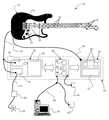
- FIG. 1is a schematic of an automatic tuning system 10 in accordance with the present invention.
- the automatic tuning system 10can be adapted to adjust the tension of a wide variety of structures including, but not limited to, wires, cables, strings, or the like. Further, the automatic tuning system 10 is particularly designed to adjust such structures to a predetermined response.
- the system 10is adapted for tuning any stringed instrument, such as a bass, piano, or violin, etc. More specifically, this embodiment of the system 10 is designed to automatically and simultaneously tune one or more strings of an instrument.
- the components and operation of the automatic tuning system 10are described in relation to the tuning of an electric guitar 12 having a body 14 , one or more strings 16 , and a manual tuner 18 for each string 16 .
- Each string 16 and each manual tuner 18is secured to the body 14 of the guitar 12 .
- a user or musicianstrums or stretches the guitar strings 16 thereby creating string vibrations.
- the automatic tuning system 10includes one or more audio input transducers 20 which produce electrical analog signals in response to the string vibrations.
- Many types of guitarsinclude one or more audio input transducers which are integral to the guitar. With such guitars, the integrated audio input transducers may be used to provide the analog signals to the automatic tuning system 10 . With the remaining guitars, one or more audio input transducers may be retrofitted to the guitar.
- the automatic tuning system 10also includes a signal interface 22 .
- the analog signals produced by the one or more audio input transducers 20are transmitted through a transducer output channel 24 to the signal interface 22 .
- the signal interface 22is designed to route and condition the analog signals for processing within the automatic tuning system 10 .
- the signal interface 22includes a signal muting circuit 26 , a signal conditioning circuit 28 , and an ADC (analog to digital converter) 30 . Each analog signal produced by the one or more audio input transducers 20 is transmitted to both the signal muting circuit 26 and the signal conditioning circuit 28 .
- each analog signalis transmitted from the signal muting circuit 26 through an amplifier output channel 32 to an audio amplifier 34 .
- the audio amplifier 34amplifies each analog signal received and produces an electrical signal which when input to an appropriate audio transducer 36 , such as a speaker, creates audible sounds. In this manner, the string vibrations created when the musician strums or stretches the strings 16 are transformed into amplified music.
- an appropriate audio transducer 36such as a speaker
- the signal muting circuit 26is designed to prevent the transmission of all analog signals to the amplifier output channel 32 and, in turn, to the audio amplifier 34 .
- the signal muting circuit 26mutes the output of the guitar 12 during automatic tuning of the guitar strings 16 . This signal muting operation can optionally be disabled.
- the signal conditioning circuit 28includes one or more signal amplifiers and signal filters to condition each analog signal from the one or more audio input transducers 20 for optimal input to the ADC 30 .
- the ADC 30converts each analog signal into a digital signal.
- Each digital signalis generated in a predetermined data format, such as a multi-bit linear code or other such structure, suitable for digital signal processing.
- the automatic tuning system 10further includes a processor 38 having a central processing unit (CPU) 40 , memory 42 , and digital signal processing capabilities 44 .
- the types of digital signal processing which may be used in the present inventioninclude, but are not limited to, lowpass filters, bandpass filters, highpass filters, demultiplexing and fast fourier transforms.
- the processor 38is also capable of standard two-way communications. Two-way communications between the processor 38 and a remotely located computer 46 are transmitted through an external interface 48 as described in greater detail below.
- a signal conditioning circuit 28 , an ADC 30 , and a processor 38are dedicated to each string 16 of the guitar 12 to be tuned.
- One of ordinary skill in the artwill recognize that there are a variety of alternative embodiments employing signal multiplexing or other means to eliminate the need for a separate signal conditioning circuit 28 and/or ADC 30 and/or processor 38 for each string 16 . These embodiments allow a trade-off between tuning speed and accuracy versus electronic complexity, size, and cost.
- the automatic tuning system 10also includes an actuator driver 50 controlled by the processor 38 .
- the actuator driver 50includes a power supply 52 , one or more driver circuits 54 , and a motor 56 for each driver circuit 54 .
- Each driver circuit 54is coupled with a separate motor 56 via an actuator output channel 58 .
- Each guitar string 16is also connected to a separate motor 56 .
- Each driver circuit 54is controlled by the processor 38 to operate or move the respective motor 56 .
- the operation of each motor 56either tautens (tightens) or slackens (loosens) the respective guitar string 16 .
- each driver circuit 54is controlled by the processor 38 to operate the respective motor 56 to increase or decrease the tension of a particular guitar string 16 .
- the operation or response of a motor 56is controlled by the type of input voltage drive profile supplied to the motor 56 by the driver circuit 54 .
- the drive profile of the input voltage signal supplied to a motor 56 by a driver circuit 54controls the operation or response of the motor 56 .
- driver circuitsThere are various types of driver circuits and, thus, drive profiles commercially available. Accordingly, one of ordinary skill in the art may select from several input voltage drive profiles each of which produces a different motor response.
- the automatic tuning system 10further includes a plurality of user interfaces, preferably a manual switch interface 60 and an external interface 48 .
- the manual switch interface 60provides a user with a manual input means at the body 14 of the guitar 12 .
- the manual switch interface 60is composed of tuning selector means, tuning actuation means, tuning learning means, communications means to a remote computer 46 , and mute disable means.
- the processor 38retrieves codes from the processor memory 42 which represent a previously stored string tuning pattern.
- the processor 38uses these codes to automatically produce said tuning pattern across the strings 16 on the guitar 12 .
- the processor 38uses the setting in the tuning selector means to determine which of a plurality of pre-stored tuning pattern codes to use for the tuning process.
- activation of the learning meanscauses the processor 38 to store tuning pattern codes in the processor memory 42 .
- the processor 38stores the tuning pattern codes into the processor memory location indicated by the tuning selector means.
- mute disable meansmuting of the signal to the audio amplifier 34 is disabled and the signal generated by the strings 16 can be heard through the audio transducer 36 .
- One embodiment of the manual switch interface 60in includes a multi-position rotary selector switch and three or more push-button switches.
- An alternative embodimentuses an electronic display with touch screen capability.
- the external interface 48is preferably the type of interface typically associated with a personal computer.
- the external interface 48is a MIDI (Music Instrument Data Interface) type interface as commonly known and accepted in the music industry.
- the external interface 48can be a standard RS232 type interface.
- One function of the external interface 48is to couple the processor 38 to a floor switch box 62 thus providing second manual switching means, similar to the manual switch interface 60 , for selecting preset string tension patterns.
- Another function of the external interface 48is to couple the processor 38 to a computer 46 for the purpose of programming one or more string tension patterns into the system 10 and for providing third manual switching means, similar to the manual switch interface 60 , for selecting preset string tension patterns.
- the processor 38is programmable and, as such, one of ordinary skill in the art could program the functionality of the interfaces 60 and 48 in a plurality of ways.
- One of ordinary skill in the artwill recognize that the present invention can be practiced without the computer 46 and/or the floor switch 62 .
- the automatic tuning system 10is designed to be installed or assembled as an original component of the guitar 12 .
- the system 10can be retrofitted to an existing guitar.
- the system 10has been adapted to preserve the original tonal qualities of the guitar 12 .
- the signal interface 22 , the processor 38 , and the actuator driver 50are contained in a case 64 packaged to the body 14 of the guitar 12 .
- the motors 56are located or packaged adjacent to the ends of the guitar strings 16 opposite the manual tuners 18 . As such, the automatic tuning system 10 does not effect or alter the typical mechanics associated with playing the guitar 12 .
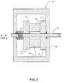
- FIG. 2is a schematic, cross-sectional view of a linear motor 56 for use in the present invention, showing the internal components of the linear motor 56 .
- the linear motor 56is shown in schematic illustration for descriptive purposes.
- the linear motor 56is encased in a housing 66 .
- the housing 66is designed to protect the linear motor 56 .
- the linear motor 56is assembled to the body 14 of the guitar 12 .
- the linear motor 56 so attachedis capable of moving a rod 68 , having any cross-sectional shape, in either direction along axis A in FIG. 2 .
- the fixed linear motor 56is capable of moving the rod 68 left or right relative to the linear motor 56 as illustrated in FIG. 2 .
- the linear motor 56operates in a walking beam feeder fashion, shown in FIG. 4 and described in greater detail below.
- the linear motor 56includes three piezo or piezoelectric actuators 70 a, 70 b, and 70 c (piezo actuator 70 a and 70 c are shown in FIG. 3 ), a pair of clamps 72 and 74 , and a resilient means 76 .
- the first clamp 72is fixed to the housing 66 and the second clamp 74 is free from the housing 66 .
- the resilient means 76may comprise an actuator retractor spring (as shown in FIG. 2 ), an o-ring or other similar type of resilient structure, or another piezo actuator.
- the resilient means 76is disposed between the second clamp 74 and the housing 66 .
- the linear motor 56further includes an electrical connector (not shown in FIG. 2) for receiving power to operate of the linear motor 56 .
- FIG. 3is a perspective view of selected internal components of the linear motor 56 used to accomplish the walking beam feeder movement.
- the two clamps 72 and 74are adapted to clamp or hold the rod 68 .
- the axis of the rod 68is aligned perpendicular to the two clamps 72 and 74 .
- the rod 68is disposed within the jaws of the two clamps 72 and 74 .
- a musical string 16is secured to the end 80 of the rod 68 adjacent to the first clamp 72 .
- a flexible structuresuch as a cable, wire or the like can be secured to the end 80 of the rod 68 adjacent to the first clamp 72 .
- the two outermost actuators 70 a and 70 care operated between an energized state, wherein voltage is applied to the actuator, and a de-energized state, wherein no voltage is applied to the actuator.
- the two outermost actuators 70 a and 70 care normally de-energized.
- the first actuator 70 ais de-energized
- the first clamp 72is closed, or clamps to or engages the rod 68 .
- the third actuator 70 cis de-energized
- the second clamp 74is closed, or clamps to or engages the rod 68 .
- Each of the three actuators 70 a-cis energized by applying a voltage to the respective actuator. Energizing the first actuator 70 a disengages the first clamp 72 from the rod 68 . Energizing the third actuator 70 c disengages the second clamp 74 from the rod 68 . In other words, energizing the first actuator 70 a opens the first clamp 72 thereby releasing the rod 68 and energizing the third actuator 70 c opens the second clamp 74 thereby releasing the rod 68 .
- the second or central actuator 70 bis disposed between the first and second clamps 72 and 74 providing a nominal displacement between the first and second clamps 72 and 74 .
- the second actuator 70 bWhen energized, the second actuator 70 b provides an increase in the displacement between the two clamps 72 and 74 .
- the second actuator 70 bwhen energized, the second actuator 70 b provides an expansion force which pushes the two clamps 72 and 74 apart or away from each other.
- the amount of increase in the displacement between the two clamps 72 and 74is proportional to the amount of voltage applied across the second actuator 70 b.
- the second actuator 70 bWhen de-energized, the second actuator 70 b provides a decrease in the displacement between the two clamps 72 and 74 .
- Piezo actuatorsespecially piezo stacks, provide a contraction force significantly lower or weaker than the aforementioned expansion force and are susceptible to failure caused by tension during contraction.
- the resilient means 76is adapted to bias or push the second clamp 74 toward the second actuator 70 b.
- the resilient means 76can provide all or part of the force necessary to move the two clamps 72 and 74 back to the nominal displacement.
- FIGS. 4A-4Gare a series of schematics illustrating an operation of the linear motor 56 for moving the rod 68 in one direction.
- FIGS. 4A-4Gillustrate a sequence of operations performed by the linear motor 56 to move the rod 68 in a direction of travel as indicated by arrow 82 .
- FIG. 4Aillustrates the linear motor 56 in a first position.
- the second actuator 70 bis de-energized and the first and second clamps 72 and 74 are clamped to the rod 68 .
- the first clamp 72is fixed to the housing 66 or anchored in a fixed location or to a fixed surface.
- voltage to each of the three actuators 70 a-cis switched off and the displacement between the first and second clamps 72 and 74 is nominal.
- FIG. 4Billustrates the linear motor 56 in a second position.
- the first clamp 72is opened by energizing the first actuator 70 a.
- the rod 68is released by the first clamp 72 .
- FIG. 4Cillustrates the linear motor 56 in a third position.
- a voltageis applied to the second actuator 70 b thus energizing the second actuator 70 b and providing an increase in the displacement between the first and second clamps 72 and 74 .
- the expansion of the second actuator 70 bforces the second clamp 74 and the rod 68 in a direction of travel as indicated by arrow 82 .
- FIG. 4Dillustrates the linear motor 56 in a fourth position.
- the first clamp 72is closed by de-energizing the first actuator 70 a. During the fourth operation, the first clamp 72 clamps to the rod 68 .
- FIG. 4Eillustrates the linear motor 56 in a fifth position.
- the second clamp 74is opened by energizing the third actuator 70 c.
- the rod 68is released by the second clamp 74 .
- FIG. 4Fillustrates the linear motor 56 in a sixth position.
- the second actuator 70 bis de-energized.
- the resilient means 76pushes the second clamp 74 in the direction of travel indicated by arrow 84 .
- FIG. 4Gillustrates the linear motor 56 in a seventh position.
- the second actuator 70 bis de-energized and the first and second clamps 72 and 74 are clamped to the rod 68 .
- voltage to each of the three actuators 70 a-cis switched off and the displacement between the first and second clamps 72 and 74 is nominal.
- the seventh positionis similar to the first position but with the rod 68 moved in the direction of travel as indicated by arrow 82 relative to the linear motor 56 .
- the linear motor 56is capable of performing the seven step operational sequence in less than or equal to approximately 400 to 4,000 microseconds.
- a single cycle of the seven step operational sequencewill nominally move or displace the rod 68 approximately 12 micrometers.
- the seven step operational sequencemay be repeated or cycled two or more times.
- the amount of voltage applied to the second actuator 70 bis reduced proportionally. For example, to move or displace the rod 68 a distance of one-half the nominal displacement produced by the second actuator 70 b, one-half the nominal voltage is applied to the second actuator 70 b.
- To move or displace the rod 80 a distance of one-quarter the nominal displacement produced by the second actuator 70 bone-quarter the nominal voltage is applied to the second actuator 70 b.
- the sequence of operations performed by the linear motor 56may be modified to move the rod 68 in the direction opposite of arrow 82 . Further, the present invention may be practiced by combining one or more operations into a single step. By moving the rod 68 in opposing directions, the linear motor 56 is capable of tightening or loosening the respective guitar string 16 . In other words, the linear motor 56 can increase or decrease the tension of the guitar string 16 .
- linear motors or like structureswhich are capable of providing tension on a string 16 may also be used within the present invention.
- FIG. 5is a cross-sectional view of one embodiment of an actuator 70 for use in the linear motor 56 of the present invention.
- the actuator 70is designed to produce a positional or spatial displacement along one predetermined axis when energized.
- the cross-section of the actuator 70is designed to expand along at least one predetermined axis when energized.
- the actuator 70includes a ceramic substrate 86 sandwiched between two opposing end caps 88 and 90 .
- the two end caps 88 and 90are preferably formed in the shape of truncated cones.
- the two end caps 88 and 90are made from sheet metal.
- Each end cap 88 and 90includes a contact surface 92 and 94 respectively.
- the entire periphery of each end cap 88 and 90is bonded to the ceramic substrate 86 .
- This type of actuator 70is commonly referred to in the art as a cymbal actuator.
- the actuator 70is operated between a de-energized state, illustrated in FIG. 5 with solid lines, providing a spatial displacement equal to the nominal thickness of the ceramic substrate 86 and the end caps 88 and 90 , and an energized state, illustrated in FIG. 5 with dashed lines, providing a spatial displacement greater than the nominal thickness of the actuator 70 .
- the actuator 70is normally de-energized.
- the actuator 70is energized by applying a voltage or potential V across the ceramic substrate 86 .
- the voltagecauses the substrate 86 to expand along the Z axis and contract along the X and Y axes as designated in FIG. 5 .
- both end caps 88 and 90flex or bow outwardly from the substrate 86 about flex points 96 , 98 and 100 , 102 , respectively.
- the contraction of the ceramic substrate 86shortens the distance between the sidewalls of each end cap 88 and 90 and increases the distance between the contact surfaces 92 and 94 . In this manner, a substantial increase in the displacement between the contact surfaces 92 and 94 is produced.
- the increase in the displacement between the contact surfaces 92 and 94 for a given cymbal geometryis proportional to the amount of voltage applied across the ceramic substrate 86 .
- a nominal voltageproduces a nominal displacement
- one-half the nominal voltageproduces one-half the nominal displacement
- one-quarter the nominal voltageproduces one-quarter the nominal displacement
- each end cap 88 and 90render it practical to stack several actuators 70 in order to achieve greater displacements.
- the present inventionmay also be practiced with other similar types of actuators including, but not limited to, a single or individual piezoelectric element, a stack of individual piezo elements, a mechanically amplified piezo element or stack, or a multilayer cofired piezo stack.
- the linear motor 56has numerous advantages, attributes, and desirable characteristics including, but not limited to, the characteristics listed hereafter.
- the present inventionincorporates relatively simple, inexpensive, low power, reliable controls. More specifically, the linear motor 56 can be powered by a battery.
- the linear motor 56is compact in size (i.e. equal to approximately 1 in 3 ) yet physically scalable to dimensions as least as much as a factor of ten greater and highly powerful (i.e. capable of exerting a drive thrust of 35 lbs.).
- the present inventionis highly precise (i.e. capable of producing movement increments of approximately 0.0005 inch), highly efficient (i.e. having an average power consumption of less than 10 Watts when operating and negligible power consumption when idle), and highly reliable (i.e. having a component life expectancy of approximately 250,000,000 cycles).
- the linear motor 56produces minimal heat during operation, generates minimal EMI (Electromagnetic Interference) and RFI (Radio-Frequency Interference), and is relatively unaffected by stray EMI and RFI in the area
- the present inventionis capable of producing an accumulated linear travel distance in excess of 2 kilometers.
- FIG. 6Aillustrates an example of a base signal 104 having a frequency.
- FIG. 6Billustrates an example of a modulation signal 106 .
- FIG. 6Cillustrates an example of a modulated motor movement signal 108 created when the base signal 104 is modulated by the modulation signal 106 .
- the modulated motor movement signal 108is produced by the processor 38 performing a logical AND function upon the base signal 104 and the modulation signal 106 .
- the resulting modulated motor movement signal 108is output from the processor 38 to the drive circuits 54 and then to the motors 56 through the actuator output channel 58 .
- the modulated motor movement signal 108causes the motors 56 to alter the tension of the strings 16 on the guitar 12 .
- FIG. 6Dillustrates an example of a resonance signal 110 generated from a string 16 in response to a signal induced on the string 16 by operation of a motor 56 driven by a modulated motor movement signal 108 .
- the signal induced on the strings 16 by the operation of the motors 56causes the strings 16 to resonate at a higher amplitude.
- the processor 38monitors the varying amplitude of the string resonance and adjusts the modulated motor movement signal 108 to attempt to maximize the amplitude of the string resonance. Practically, the processor 38 may have to overshoot the maximum resonance amplitude to achieve the desired tuning. When the processor 38 detects optimal amplitude from each string 16 , the processor 38 discontinues generating modulated motor movement signals 108 and the tuning process for the guitar 12 is complete.
- Activation of the tuning process and selection of the specific tuning to be achievedare initiated and determined by operation of the manual switch interface 60 , the foot box 62 , or the remote computer 46 described above.
- the codes for base signals 104are stored in the processor memory 42 .
- the base signals 104are selected to optimize the results of the modulation and tuning process.
- the modulation signal 106 for each tuningis developed during the tuning learning process.
- the tuning learning processis initiated by activation of the tuning learning means described above.
- the modulation signal codesare stored in processor memory locations determined by the setting of the tuning selector means described above.
- the first step in the tuning learning processis for the user or musician to manually tune the guitar 12 for the desired sound.
- the musicianpositions the tuning selector means and activates the tuning learning means.
- the musicianstrums the strings 16 on the guitar 12 . This action provides a musical signal to the processor 38 .
- the processor 38uses the musical signal from each string 16 to develop a modulation signal 106 .
- the processor 38stores the codes for the modulation signal 106 in the processor memory 42 . These stored codes for the modulation signal 106 can be used during a subsequent tuning process by the processor 38 to adjust the tuning of the guitar 12 as described above.
- the tuningscan be developed and/or stored in a remote computer 46 .
- the remote computer 46can be connected to the guitar 12 .
- the processor 38may select codes for modulation signals 106 of tunings stored in the remote computer 46 . Upon such selection and electronic transfer of the appropriate codes from the remote computer 46 to the processor 38 , actual tuning of the guitar 12 would occur as described above. In like fashion, codes for a tuning could be electronically transferred from the processor 38 to the remote computer 46 .
- selection and activation of the tuning processis accomplished via the foot switch box 62 as described above.
- the foot switch box 62operates in a fashion similar to the manual switch interface 60 . Use of the foot switch box 62 would allow a musician to cause the guitar 12 to obtain an alternative tuning while leaving the musician's hands free for other activities.
Landscapes
- Physics & Mathematics (AREA)
- Engineering & Computer Science (AREA)
- Acoustics & Sound (AREA)
- Multimedia (AREA)
- Stringed Musical Instruments (AREA)
Abstract
Description
Claims (20)
Priority Applications (1)
| Application Number | Priority Date | Filing Date | Title |
|---|---|---|---|
| US09/801,347US6437226B2 (en) | 2000-03-07 | 2001-03-07 | Method and system for automatically tuning a stringed instrument |
Applications Claiming Priority (2)
| Application Number | Priority Date | Filing Date | Title |
|---|---|---|---|
| US18759700P | 2000-03-07 | 2000-03-07 | |
| US09/801,347US6437226B2 (en) | 2000-03-07 | 2001-03-07 | Method and system for automatically tuning a stringed instrument |
Publications (2)
| Publication Number | Publication Date |
|---|---|
| US20010029828A1 US20010029828A1 (en) | 2001-10-18 |
| US6437226B2true US6437226B2 (en) | 2002-08-20 |
Family
ID=22689632
Family Applications (1)
| Application Number | Title | Priority Date | Filing Date |
|---|---|---|---|
| US09/801,347Expired - Fee RelatedUS6437226B2 (en) | 2000-03-07 | 2001-03-07 | Method and system for automatically tuning a stringed instrument |
Country Status (3)
| Country | Link |
|---|---|
| US (1) | US6437226B2 (en) |
| AU (1) | AU2001243481A1 (en) |
| WO (1) | WO2001067431A1 (en) |
Cited By (28)
| Publication number | Priority date | Publication date | Assignee | Title |
|---|---|---|---|---|
| US20040025675A1 (en)* | 2002-02-19 | 2004-02-12 | Yamaha Corporation | Method of configurating acoustic correction filter for stringed instrument |
| US20040045148A1 (en)* | 2002-06-21 | 2004-03-11 | Jeff Moler | Uni-body piezoelectric motor |
| US20040187673A1 (en)* | 2003-03-31 | 2004-09-30 | Alexander J. Stevenson | Automatic pitch processing for electric stringed instruments |
| US7049502B2 (en) | 2003-10-24 | 2006-05-23 | Korg, Inc | Music tuner |
| US20060185499A1 (en)* | 2005-01-21 | 2006-08-24 | D Addario James A | Optical display interface for electronic tuner for musical instruments |
| US20070006712A1 (en)* | 2005-07-11 | 2007-01-11 | Lyles Cosmos M | Stringed instrument that maintains relative tune |
| US20070012161A1 (en)* | 2005-07-11 | 2007-01-18 | Lyles Cosmos M | Stringed instrument that maintains relative tune |
| US20070214935A1 (en)* | 2006-03-15 | 2007-09-20 | Cosmos Lyles | Stringed musical instrument using spring tension |
| US20070221035A1 (en)* | 2006-03-22 | 2007-09-27 | Yamaha Corporation | Automatic playing system used for musical instruments and computer program used therein for self-teaching |
| US7285710B1 (en) | 2005-01-04 | 2007-10-23 | Henry Burnett Wallace | Musical instrument tuner |
| US20080276787A1 (en)* | 2005-03-17 | 2008-11-13 | Christopher Adams | Device for Automatically Tuning a String of a Stringed Instrument |
| US20080282869A1 (en)* | 2004-05-13 | 2008-11-20 | Christopher Adams | Device and Method for Automatically Tuning a Stringed Instrument, Particularly a Guitar |
| US20090288547A1 (en)* | 2007-02-05 | 2009-11-26 | U.S. Music Corporation | Method and Apparatus for Tuning a Stringed Instrument |
| US7692079B2 (en) | 2007-01-11 | 2010-04-06 | Intune Technologies, Llc | Stringed musical instrument |
| US20100089219A1 (en)* | 2008-10-14 | 2010-04-15 | D Arco Daniel | Tuning Stabilizer for Stringed Instrument |
| US7855330B2 (en) | 2008-01-17 | 2010-12-21 | Intune Technologies Llc | Modular bridge for stringed musical instrument |
| US20110197743A1 (en)* | 2010-02-17 | 2011-08-18 | Potter Dalton L | Stringed musical instrument tuner for simultaneously tuning all strings while muting the instrument |
| US20140069258A1 (en)* | 2012-09-11 | 2014-03-13 | Overtone Labs, Inc. | Timpani tuning and pitch control system |
| US8779258B2 (en) | 2012-01-19 | 2014-07-15 | Intune Technologies, Llc | Stringed musical instrument using spring tension |
| US9135904B2 (en)* | 2010-01-22 | 2015-09-15 | Overtone Labs, Inc. | Drum and drum-set tuner |
| US9190031B1 (en) | 2014-05-02 | 2015-11-17 | Don Gilmore Devices, Llc | Piano string tuning using inductive current pumps and associated method of use |
| US9196235B2 (en) | 2010-07-28 | 2015-11-24 | Ernie Ball, Inc. | Musical instrument switching system |
| US20150370176A1 (en)* | 2008-07-22 | 2015-12-24 | Carl Zeiss Smt Gmbh | Actuators and microlithography projection exposure systems and methods using the same |
| US9484007B1 (en) | 2015-11-18 | 2016-11-01 | Geoffrey Lee McCabe | Tremolo stop tuner and tremolo stabilizer |
| US9847076B1 (en) | 2016-10-18 | 2017-12-19 | Geoffrey Lee McCabe | Tremolo spring and stabilizer tuner |
| US10586518B2 (en)* | 2017-03-27 | 2020-03-10 | Band Industries, Inc. | Automatic tuning methods and systems |
| US11562721B2 (en)* | 2020-03-13 | 2023-01-24 | Don Gilmore Devices, Llc | Wireless multi-string tuner for stringed instruments and associated method of use |
| US12380871B2 (en) | 2022-01-21 | 2025-08-05 | Band Industries Holding SAL | System, apparatus, and method for recording sound |
Families Citing this family (5)
| Publication number | Priority date | Publication date | Assignee | Title |
|---|---|---|---|---|
| ITRM20010462A1 (en)* | 2001-07-31 | 2003-01-31 | Marcello Modugno | ELECTRONIC AUTOMATIC TUNING DEVICE FOR GUITARS AND OTHER MUSICAL INSTRUMENTS. |
| WO2006097125A1 (en) | 2005-03-17 | 2006-09-21 | Tectus Anstalt | Device for adjusting the tension of the strings of a stringed instrument |
| US7534955B2 (en) | 2005-03-17 | 2009-05-19 | Tectus Anstalt | Device and method for adjusting the tension of a string of a stringed instrument |
| US7598450B2 (en)* | 2007-04-19 | 2009-10-06 | Marcodi Musical Products, Llc | Stringed musical instrument with improved method and apparatus for tuning and signal processing |
| US8927838B2 (en)* | 2010-09-21 | 2015-01-06 | Bassam Fouad Jalgha | Universal musical string adjusting apparatus for use with a tuning device |
Citations (122)
| Publication number | Priority date | Publication date | Assignee | Title |
|---|---|---|---|---|
| US3144802A (en) | 1961-06-01 | 1964-08-18 | Jr Lawrence P Faber | Tuning apparatus |
| US3614486A (en) | 1969-11-10 | 1971-10-19 | Physics Int Co | Lever motion multiplier driven by electroexpansive material |
| US3666975A (en) | 1970-05-18 | 1972-05-30 | Ultrasonic Systems | Ultrasonic motors |
| US3902085A (en) | 1974-11-25 | 1975-08-26 | Burleigh Instr | Electromechanical translation apparatus |
| US3902084A (en) | 1974-05-30 | 1975-08-26 | Burleigh Instr | Piezoelectric electromechanical translation apparatus |
| US4018124A (en) | 1975-11-26 | 1977-04-19 | Rosado Ruperto L | Automatic guitar tuner for electric guitars |
| US4044239A (en) | 1975-02-28 | 1977-08-23 | Nippon Gakki Seizo Kabushiki Kaisha | Method and apparatus for adjusting vibration frequency of vibrating object |
| US4088052A (en) | 1976-11-02 | 1978-05-09 | Hedrick W David | String instrument tuning apparatus |
| US4088916A (en) | 1975-08-28 | 1978-05-09 | Siemens Aktiengesellschaft | Piezoelectric pressure pickup |
| US4112879A (en) | 1975-02-24 | 1978-09-12 | Robert Bosch Gmbh | Process for the regulation of the optimum operational behavior of an internal combustion engine |
| US4157802A (en) | 1977-07-15 | 1979-06-12 | Burleigh Instruments, Inc. | Rigid thermally stable structure for supporting precision devices |
| US4196652A (en) | 1974-08-19 | 1980-04-08 | Jef Raskin | Digital electronic tuner |
| US4208636A (en) | 1977-12-16 | 1980-06-17 | Burleigh Instruments, Inc. | Laser apparatus |
| US4207791A (en) | 1977-06-25 | 1980-06-17 | Kabushiki Kaisha Kawai Gakki Seisakusho | Automatic tuning device |
| US4228680A (en) | 1978-02-08 | 1980-10-21 | Robert Bosch Gmbh | Device for detecting the onset of fuel injection |
| US4313361A (en) | 1980-03-28 | 1982-02-02 | Kawai Musical Instruments Mfg. Co., Ltd. | Digital frequency follower for electronic musical instruments |
| US4319843A (en) | 1980-02-25 | 1982-03-16 | Burleigh Instruments, Inc. | Interferometer apparatus for the direct measurement of wavelength and frequency |
| US4327623A (en) | 1979-04-12 | 1982-05-04 | Nippon Gakki Seizo Kabushiki Kaisha | Reference frequency signal generator for tuning apparatus |
| US4336809A (en) | 1980-03-17 | 1982-06-29 | Burleigh Instruments, Inc. | Human and animal tissue photoradiation system and method |
| US4388908A (en) | 1980-10-23 | 1983-06-21 | Robert Bosch Gmbh | Electrically controlled valve operating system, particularly for fuel injection |
| US4426981A (en) | 1981-05-09 | 1984-01-24 | Robert Bosch Gmbh | Apparatus for detecting the fuel quantity delivered to the combustion chambers of a diesel engine |
| US4426907A (en) | 1981-09-10 | 1984-01-24 | Scholz Donald T | Automatic tuning device |
| US4430899A (en) | 1981-06-05 | 1984-02-14 | Robert Bosch Gmbh | Fluid pressure sensor, particularly diesel engine injection pump pressure sensor |
| US4432228A (en) | 1981-01-22 | 1984-02-21 | Robert Bosch Gmbh | Fuel injection arrangement |
| US4434753A (en) | 1981-05-18 | 1984-03-06 | Nippon Soken, Inc. | Ignition apparatus for internal combustion engine |
| US4463727A (en) | 1981-09-08 | 1984-08-07 | Robert Bosch Gmbh | Diesel engine fuel injection system |
| US4468583A (en) | 1982-10-22 | 1984-08-28 | Hitachi, Ltd. | Piezoelectric rotary actuator |
| US4479475A (en) | 1981-12-09 | 1984-10-30 | Robert Bosch Gmbh | Pressurized fuel injection system for multi-cylinder engines, particularly diesel engines |
| US4570096A (en) | 1983-10-27 | 1986-02-11 | Nec Corporation | Electromechanical translation device comprising an electrostrictive driver of a stacked ceramic capacitor type |
| US4580540A (en) | 1979-10-17 | 1986-04-08 | Robert Bosch Gmbh | Fuel injection pump for internal combustion engines |
| US4584923A (en) | 1985-03-05 | 1986-04-29 | Minnick Gregory B | Self tuning tail piece for string instruments |
| US4617952A (en) | 1984-07-31 | 1986-10-21 | Yamatake-Honeywell Co. Limited | Switching valve and an electro-pneumatic pressure converter utilizing the same |
| US4629926A (en) | 1985-10-21 | 1986-12-16 | Kiwi Coders Corporation | Mounting for piezoelectric bender of fluid control device |
| US4660523A (en) | 1984-11-09 | 1987-04-28 | Robert Bosch Gmbh | Piezoelectric control block |
| US4667639A (en) | 1985-07-25 | 1987-05-26 | Robert Bosch Gmbh | Distributor injection pump for internal combustion engines |
| US4697118A (en) | 1986-08-15 | 1987-09-29 | General Electric Company | Piezoelectric switch |
| US4714855A (en) | 1985-05-07 | 1987-12-22 | Nec Corporation | Piezo-electric actuator and stepping device using same |
| US4725002A (en) | 1985-09-17 | 1988-02-16 | Robert Bosch Gmbh | Measuring valve for dosing liquids or gases |
| US4732071A (en) | 1987-02-13 | 1988-03-22 | Kawai Musical Instrument Mfg. Co., Ltd | Tuning indicator for musical instruments |
| US4735185A (en) | 1985-06-14 | 1988-04-05 | Nippondenso Co., Ltd. | Apparatus for feeding high-pressure fuel into engine cylinder for injection control |
| US4736131A (en) | 1985-07-30 | 1988-04-05 | Nec Corporation | Linear motor driving device |
| US4749897A (en) | 1986-03-12 | 1988-06-07 | Nippondenso Co., Ltd. | Driving device for piezoelectric element |
| US4750706A (en) | 1985-09-24 | 1988-06-14 | Robert Bosch Gmbh | Valve for dosing liquids or gases |
| US4757223A (en) | 1986-01-21 | 1988-07-12 | Dainippon Screen Mfg. Co., Ltd. | Linear actuator |
| US4777398A (en) | 1984-08-31 | 1988-10-11 | Tokyo Juki Industrial Co., Ltd. | Piezoelectric motor |
| US4793313A (en) | 1986-04-10 | 1988-12-27 | Robert Bosch Gmbh | Fuel injection apparatus for internal combustion engines |
| US4803908A (en) | 1987-12-04 | 1989-02-14 | Skinn Neil C | Automatic musical instrument tuning system |
| US4821726A (en) | 1986-11-07 | 1989-04-18 | Nippondenso Co., Ltd. | Electronic fuel injection device |
| US4838233A (en) | 1986-03-05 | 1989-06-13 | Nippondenso Co., Ltd. | Pilot injection system for fuel injection pump |
| US4874979A (en) | 1988-10-03 | 1989-10-17 | Burleigh Instruments, Inc. | Electromechanical translation apparatus |
| US4893750A (en) | 1987-08-15 | 1990-01-16 | Lucas Industries Public Limited Company | Fuel injection nozzle |
| US4909126A (en) | 1987-12-04 | 1990-03-20 | Transperformance, Inc. | Automatic musical instrument tuning system |
| US4940037A (en) | 1987-07-06 | 1990-07-10 | Robert Bosch Gmbh | Fuel injection system for internal combustion engines |
| US4947077A (en) | 1986-12-03 | 1990-08-07 | Jgc Corporation | Drive apparatus and motor unit using the same |
| US5009142A (en) | 1990-03-26 | 1991-04-23 | Kurtz Noel T | Means and method for automatic resonance tuning |
| US5027027A (en) | 1988-08-02 | 1991-06-25 | Quick Technologies Ltd. | Electromechanical translation apparatus |
| US5034647A (en) | 1988-09-29 | 1991-07-23 | Canon Kabushiki Kaisha | Inchworm type driving mechanism |
| US5038657A (en) | 1990-07-02 | 1991-08-13 | Busley Bradford M | String tensioning apparatus for a musical instrument |
| US5040514A (en) | 1989-11-30 | 1991-08-20 | Robert Bosch Gmbh | Arrangement for injecting fuel for an internal combustion engine |
| US5065660A (en) | 1990-05-29 | 1991-11-19 | Buda Eric De | Piano tuning system |
| US5080079A (en) | 1989-09-22 | 1992-01-14 | Aisin Seiki Kabushiki Kaisha | Fuel injection apparatus having fuel pressurizing pump |
| US5094429A (en) | 1990-03-09 | 1992-03-10 | Siemens Aktiengesellschaft | Valve having piezoelecrtric drive |
| US5109885A (en) | 1988-11-15 | 1992-05-05 | Robert Bosch Gmbh | Solenoid valve, in particular for fuel-injection pumps |
| US5157256A (en) | 1991-08-08 | 1992-10-20 | Burleigh Instruments Inc. | System for exchanging samples and electrode tip units in a surface probe microscope |
| US5161774A (en) | 1989-06-19 | 1992-11-10 | Robert Bosch Gmbh | Microvalve |
| US5182484A (en) | 1991-06-10 | 1993-01-26 | Rockwell International Corporation | Releasing linear actuator |
| US5199641A (en) | 1988-09-29 | 1993-04-06 | Siemens Aktiengesellschaft | Fuel injection nozzle with controllable fuel jet characteristic |
| US5237238A (en) | 1990-07-21 | 1993-08-17 | Omicron Vakuumphysik Gmbh | Adjusting device for microscopic movements |
| US5314175A (en) | 1990-02-27 | 1994-05-24 | Matsushita Electric Industrial Co., Ltd. | Wire clamping device and wire clamping method |
| US5319257A (en) | 1992-07-13 | 1994-06-07 | Martin Marietta Energy Systems, Inc. | Unitaxial constant velocity microactuator |
| US5323680A (en) | 1992-05-29 | 1994-06-28 | Miller Mark D | Device and method for automatically tuning a stringed musical instrument |
| US5328149A (en) | 1992-06-19 | 1994-07-12 | Marco Systemanalyse Und Entwicklung Gmbh | Apparatus for operating a valve element |
| US5332942A (en) | 1993-06-07 | 1994-07-26 | Rennex Brian G | Inchworm actuator |
| US5335862A (en) | 1992-11-05 | 1994-08-09 | Elopak Systems A.G. | Discharge nozzle for a liquid filling assembly |
| US5343793A (en) | 1992-10-06 | 1994-09-06 | Michael Pattie | Automatically tuned musical instrument |
| US5390579A (en) | 1990-06-25 | 1995-02-21 | Torque Talk Limited | Tuning of musical instruments |
| US5410206A (en) | 1993-04-06 | 1995-04-25 | New Focus, Inc. | Piezoelectric actuator for optical alignment screws |
| US5413076A (en) | 1993-04-08 | 1995-05-09 | Robert Bosch Gmbh | Fuel injection system for internal combustion engines |
| US5425343A (en) | 1993-01-19 | 1995-06-20 | Aisin Seiki Kabushiki Kaisha | Fuel injection control device for internal combustion engine |
| US5435477A (en) | 1993-03-09 | 1995-07-25 | Kabushiki Kaisha Shinkawa | Wire clampers |
| US5460202A (en) | 1993-11-22 | 1995-10-24 | Landis & Gyr Powers, Inc. | Three-way piezoelectric valve |
| US5465021A (en) | 1992-10-02 | 1995-11-07 | U. S. Philips Corporation | Electromechanical displacement device and actuator suitable for use in such a electromechanical displacement device |
| US5477831A (en) | 1993-01-19 | 1995-12-26 | Aisin Seiki Kabushiki Kaisha | Fuel injection control device for internal combustion engine |
| US5482213A (en) | 1993-05-31 | 1996-01-09 | Aisin Seiki Kabushiki Kaisha | Fuel injection valve operated by expansion and contraction of piezoelectric element |
| US5518184A (en) | 1993-09-22 | 1996-05-21 | Robert Bosch Gmbh | Fuel injection nozzle for internal combustion engines |
| US5645226A (en) | 1995-02-13 | 1997-07-08 | Siemens Automotive Corporation | Solenoid motion initiator |
| US5685485A (en) | 1994-03-22 | 1997-11-11 | Siemens Aktiengesellschaft | Apparatus for apportioning and atomizing fluids |
| US5697554A (en) | 1995-01-12 | 1997-12-16 | Robert Bosch Gmbh | Metering valve for metering a fluid |
| US5712524A (en) | 1994-12-27 | 1998-01-27 | Nec Corporation | Piezoelectric rotation driving apparatus |
| US5751090A (en) | 1995-05-17 | 1998-05-12 | Burleigh Instruments Inc | Peristaltic driver apparatus |
| US5780957A (en) | 1996-11-12 | 1998-07-14 | Meritor Light Vehicle Systems, Inc. | Moving linear piezoelectric motor for vehicle applications |
| US5779149A (en) | 1996-07-02 | 1998-07-14 | Siemens Automotive Corporation | Piezoelectric controlled common rail injector with hydraulic amplification of piezoelectric stroke |
| US5780759A (en) | 1995-01-12 | 1998-07-14 | Blue Chip Music Gmbh | Method for pitch recognition, in particular for musical instruments which are excited by plucking or striking |
| US5780956A (en) | 1996-11-12 | 1998-07-14 | Meritor Light Vehicle Systems, Inc. | Rotary piezoelectric motor for vehicle applications |
| US5803370A (en) | 1995-12-09 | 1998-09-08 | Robert Bosch Gmbh | Fuel injection valve for internal combustion engines |
| US5810255A (en) | 1995-08-29 | 1998-09-22 | Robert Bosch Gmbh | Clamping device for a piesoelectric actuator of a fuel injection valve for internal combustion engines |
| US5824929A (en) | 1995-07-14 | 1998-10-20 | Transperformance, Llc | Musical instrument self-tuning system with calibration library |
| US5824937A (en) | 1993-12-18 | 1998-10-20 | Yamaha Corporation | Signal analysis device having at least one stretched string and one pickup |
| US5831264A (en) | 1996-10-22 | 1998-11-03 | Burleigh Instruments, Inc. | Electrostrictive actuator for scanned-probe microscope |
| US5847387A (en) | 1996-09-10 | 1998-12-08 | Burleigh Instruments, Inc. | Support device and stage assembly for a scanned-probe microscope |
| US5859378A (en) | 1995-07-14 | 1999-01-12 | Transperformance Llc | Musical instrument self-tuning system with capo mode |
| US5875764A (en) | 1998-05-13 | 1999-03-02 | Siemens Aktiengesellschaft | Apparatus and method for valve control |
| US5881767A (en) | 1997-06-04 | 1999-03-16 | Dragerwerk Ag | Modular piezo valve arrangement |
| US5883323A (en) | 1996-08-30 | 1999-03-16 | Kaufman; Jay Stephen | Sense of touch electronic tuner |
| US5886270A (en) | 1996-04-22 | 1999-03-23 | Wynn; David S. | Electormechanical tuner for stringed instruments |
| US5901896A (en) | 1997-06-26 | 1999-05-11 | Kulicke And Soffa Investments, Inc | Balanced low mass miniature wire clamp |
| US5907212A (en) | 1996-03-06 | 1999-05-25 | Minolta Co., Ltd. | Apparatus provided with electro-mechanical transducer |
| US5907269A (en) | 1997-06-06 | 1999-05-25 | Etrema Products, Inc. | Magnetostrictive clamping device |
| EP0704916B1 (en) | 1994-09-29 | 1999-08-04 | Nec Corporation | Output-enlarged piezoelectric clamp device |
| US5934976A (en) | 1996-05-15 | 1999-08-10 | Denso Corporation | Method for grinding a taper surface and grinding apparatus using the same |
| US5977467A (en) | 1995-07-14 | 1999-11-02 | Transperformance, Llc | Frequency display for an automatically tuned stringed instrument |
| US5975428A (en) | 1996-06-15 | 1999-11-02 | Robert Bosch Gmbh | Fuel injection device for internal combustion engines |
| US6016040A (en) | 1996-08-14 | 2000-01-18 | Siemens Aktiengesellschaft | Device and method for driving at least one capacitive actuator |
| US6021760A (en) | 1997-07-30 | 2000-02-08 | Robert Bosch Gmbh | Fuel injection device for internal combustion engines |
| US6025671A (en) | 1997-03-27 | 2000-02-15 | Robert Bosch Gmbh | Piezoelectric actuator |
| US6035722A (en) | 1997-11-04 | 2000-03-14 | Robert Bosch Gmbh | Pressure sensor for detecting the pressure in a pump work chamber of a fuel injection pump |
| US6040643A (en) | 1997-11-20 | 2000-03-21 | Thermotrex Corporation | Linear actuator |
| US6060814A (en) | 1996-08-14 | 2000-05-09 | Siemens Aktiengesellschaft | Device and method for driving at least one capacitive actuator |
| US6062533A (en) | 1998-05-14 | 2000-05-16 | Siemens Aktiengesellschaft | Apparatus and method for valve control |
| US6104125A (en) | 1998-01-26 | 2000-08-15 | Industrial Technology Research Institute | Linear actuator |
| US6131879A (en) | 1996-11-25 | 2000-10-17 | Fraunhofer-Gesellschaft Zur Forderung Der Angewandten Forschung E.V. | Piezoelectrically actuated microvalve |
| US6166307A (en) | 1998-11-16 | 2000-12-26 | Caulkins; Kenneth B. | Apparatus for automating a stringed instrument |
- 2001
- 2001-03-07USUS09/801,347patent/US6437226B2/ennot_activeExpired - Fee Related
- 2001-03-07WOPCT/US2001/007284patent/WO2001067431A1/enactiveApplication Filing
- 2001-03-07AUAU2001243481Apatent/AU2001243481A1/ennot_activeAbandoned
Patent Citations (122)
| Publication number | Priority date | Publication date | Assignee | Title |
|---|---|---|---|---|
| US3144802A (en) | 1961-06-01 | 1964-08-18 | Jr Lawrence P Faber | Tuning apparatus |
| US3614486A (en) | 1969-11-10 | 1971-10-19 | Physics Int Co | Lever motion multiplier driven by electroexpansive material |
| US3666975A (en) | 1970-05-18 | 1972-05-30 | Ultrasonic Systems | Ultrasonic motors |
| US3902084A (en) | 1974-05-30 | 1975-08-26 | Burleigh Instr | Piezoelectric electromechanical translation apparatus |
| US4196652A (en) | 1974-08-19 | 1980-04-08 | Jef Raskin | Digital electronic tuner |
| US3902085A (en) | 1974-11-25 | 1975-08-26 | Burleigh Instr | Electromechanical translation apparatus |
| US4112879A (en) | 1975-02-24 | 1978-09-12 | Robert Bosch Gmbh | Process for the regulation of the optimum operational behavior of an internal combustion engine |
| US4044239A (en) | 1975-02-28 | 1977-08-23 | Nippon Gakki Seizo Kabushiki Kaisha | Method and apparatus for adjusting vibration frequency of vibrating object |
| US4088916A (en) | 1975-08-28 | 1978-05-09 | Siemens Aktiengesellschaft | Piezoelectric pressure pickup |
| US4018124A (en) | 1975-11-26 | 1977-04-19 | Rosado Ruperto L | Automatic guitar tuner for electric guitars |
| US4088052A (en) | 1976-11-02 | 1978-05-09 | Hedrick W David | String instrument tuning apparatus |
| US4207791A (en) | 1977-06-25 | 1980-06-17 | Kabushiki Kaisha Kawai Gakki Seisakusho | Automatic tuning device |
| US4157802A (en) | 1977-07-15 | 1979-06-12 | Burleigh Instruments, Inc. | Rigid thermally stable structure for supporting precision devices |
| US4208636A (en) | 1977-12-16 | 1980-06-17 | Burleigh Instruments, Inc. | Laser apparatus |
| US4228680A (en) | 1978-02-08 | 1980-10-21 | Robert Bosch Gmbh | Device for detecting the onset of fuel injection |
| US4327623A (en) | 1979-04-12 | 1982-05-04 | Nippon Gakki Seizo Kabushiki Kaisha | Reference frequency signal generator for tuning apparatus |
| US4580540A (en) | 1979-10-17 | 1986-04-08 | Robert Bosch Gmbh | Fuel injection pump for internal combustion engines |
| US4319843A (en) | 1980-02-25 | 1982-03-16 | Burleigh Instruments, Inc. | Interferometer apparatus for the direct measurement of wavelength and frequency |
| US4336809A (en) | 1980-03-17 | 1982-06-29 | Burleigh Instruments, Inc. | Human and animal tissue photoradiation system and method |
| US4313361A (en) | 1980-03-28 | 1982-02-02 | Kawai Musical Instruments Mfg. Co., Ltd. | Digital frequency follower for electronic musical instruments |
| US4388908A (en) | 1980-10-23 | 1983-06-21 | Robert Bosch Gmbh | Electrically controlled valve operating system, particularly for fuel injection |
| US4432228A (en) | 1981-01-22 | 1984-02-21 | Robert Bosch Gmbh | Fuel injection arrangement |
| US4426981A (en) | 1981-05-09 | 1984-01-24 | Robert Bosch Gmbh | Apparatus for detecting the fuel quantity delivered to the combustion chambers of a diesel engine |
| US4434753A (en) | 1981-05-18 | 1984-03-06 | Nippon Soken, Inc. | Ignition apparatus for internal combustion engine |
| US4430899A (en) | 1981-06-05 | 1984-02-14 | Robert Bosch Gmbh | Fluid pressure sensor, particularly diesel engine injection pump pressure sensor |
| US4463727A (en) | 1981-09-08 | 1984-08-07 | Robert Bosch Gmbh | Diesel engine fuel injection system |
| US4426907A (en) | 1981-09-10 | 1984-01-24 | Scholz Donald T | Automatic tuning device |
| US4479475A (en) | 1981-12-09 | 1984-10-30 | Robert Bosch Gmbh | Pressurized fuel injection system for multi-cylinder engines, particularly diesel engines |
| US4468583A (en) | 1982-10-22 | 1984-08-28 | Hitachi, Ltd. | Piezoelectric rotary actuator |
| US4570096A (en) | 1983-10-27 | 1986-02-11 | Nec Corporation | Electromechanical translation device comprising an electrostrictive driver of a stacked ceramic capacitor type |
| US4617952A (en) | 1984-07-31 | 1986-10-21 | Yamatake-Honeywell Co. Limited | Switching valve and an electro-pneumatic pressure converter utilizing the same |
| US4777398A (en) | 1984-08-31 | 1988-10-11 | Tokyo Juki Industrial Co., Ltd. | Piezoelectric motor |
| US4660523A (en) | 1984-11-09 | 1987-04-28 | Robert Bosch Gmbh | Piezoelectric control block |
| US4584923A (en) | 1985-03-05 | 1986-04-29 | Minnick Gregory B | Self tuning tail piece for string instruments |
| US4714855A (en) | 1985-05-07 | 1987-12-22 | Nec Corporation | Piezo-electric actuator and stepping device using same |
| US4735185A (en) | 1985-06-14 | 1988-04-05 | Nippondenso Co., Ltd. | Apparatus for feeding high-pressure fuel into engine cylinder for injection control |
| US4667639A (en) | 1985-07-25 | 1987-05-26 | Robert Bosch Gmbh | Distributor injection pump for internal combustion engines |
| US4736131A (en) | 1985-07-30 | 1988-04-05 | Nec Corporation | Linear motor driving device |
| US4725002A (en) | 1985-09-17 | 1988-02-16 | Robert Bosch Gmbh | Measuring valve for dosing liquids or gases |
| US4750706A (en) | 1985-09-24 | 1988-06-14 | Robert Bosch Gmbh | Valve for dosing liquids or gases |
| US4629926A (en) | 1985-10-21 | 1986-12-16 | Kiwi Coders Corporation | Mounting for piezoelectric bender of fluid control device |
| US4757223A (en) | 1986-01-21 | 1988-07-12 | Dainippon Screen Mfg. Co., Ltd. | Linear actuator |
| US4838233A (en) | 1986-03-05 | 1989-06-13 | Nippondenso Co., Ltd. | Pilot injection system for fuel injection pump |
| US4749897A (en) | 1986-03-12 | 1988-06-07 | Nippondenso Co., Ltd. | Driving device for piezoelectric element |
| US4793313A (en) | 1986-04-10 | 1988-12-27 | Robert Bosch Gmbh | Fuel injection apparatus for internal combustion engines |
| US4697118A (en) | 1986-08-15 | 1987-09-29 | General Electric Company | Piezoelectric switch |
| US4821726A (en) | 1986-11-07 | 1989-04-18 | Nippondenso Co., Ltd. | Electronic fuel injection device |
| US4947077A (en) | 1986-12-03 | 1990-08-07 | Jgc Corporation | Drive apparatus and motor unit using the same |
| US4732071A (en) | 1987-02-13 | 1988-03-22 | Kawai Musical Instrument Mfg. Co., Ltd | Tuning indicator for musical instruments |
| US4940037A (en) | 1987-07-06 | 1990-07-10 | Robert Bosch Gmbh | Fuel injection system for internal combustion engines |
| US4893750A (en) | 1987-08-15 | 1990-01-16 | Lucas Industries Public Limited Company | Fuel injection nozzle |
| US4803908A (en) | 1987-12-04 | 1989-02-14 | Skinn Neil C | Automatic musical instrument tuning system |
| US4909126A (en) | 1987-12-04 | 1990-03-20 | Transperformance, Inc. | Automatic musical instrument tuning system |
| US5027027A (en) | 1988-08-02 | 1991-06-25 | Quick Technologies Ltd. | Electromechanical translation apparatus |
| US5034647A (en) | 1988-09-29 | 1991-07-23 | Canon Kabushiki Kaisha | Inchworm type driving mechanism |
| US5199641A (en) | 1988-09-29 | 1993-04-06 | Siemens Aktiengesellschaft | Fuel injection nozzle with controllable fuel jet characteristic |
| US4874979A (en) | 1988-10-03 | 1989-10-17 | Burleigh Instruments, Inc. | Electromechanical translation apparatus |
| US5109885A (en) | 1988-11-15 | 1992-05-05 | Robert Bosch Gmbh | Solenoid valve, in particular for fuel-injection pumps |
| US5161774A (en) | 1989-06-19 | 1992-11-10 | Robert Bosch Gmbh | Microvalve |
| US5080079A (en) | 1989-09-22 | 1992-01-14 | Aisin Seiki Kabushiki Kaisha | Fuel injection apparatus having fuel pressurizing pump |
| US5040514A (en) | 1989-11-30 | 1991-08-20 | Robert Bosch Gmbh | Arrangement for injecting fuel for an internal combustion engine |
| US5314175A (en) | 1990-02-27 | 1994-05-24 | Matsushita Electric Industrial Co., Ltd. | Wire clamping device and wire clamping method |
| US5094429A (en) | 1990-03-09 | 1992-03-10 | Siemens Aktiengesellschaft | Valve having piezoelecrtric drive |
| US5009142A (en) | 1990-03-26 | 1991-04-23 | Kurtz Noel T | Means and method for automatic resonance tuning |
| US5065660A (en) | 1990-05-29 | 1991-11-19 | Buda Eric De | Piano tuning system |
| US5390579A (en) | 1990-06-25 | 1995-02-21 | Torque Talk Limited | Tuning of musical instruments |
| US5038657A (en) | 1990-07-02 | 1991-08-13 | Busley Bradford M | String tensioning apparatus for a musical instrument |
| US5237238A (en) | 1990-07-21 | 1993-08-17 | Omicron Vakuumphysik Gmbh | Adjusting device for microscopic movements |
| US5182484A (en) | 1991-06-10 | 1993-01-26 | Rockwell International Corporation | Releasing linear actuator |
| US5157256A (en) | 1991-08-08 | 1992-10-20 | Burleigh Instruments Inc. | System for exchanging samples and electrode tip units in a surface probe microscope |
| US5323680A (en) | 1992-05-29 | 1994-06-28 | Miller Mark D | Device and method for automatically tuning a stringed musical instrument |
| US5328149A (en) | 1992-06-19 | 1994-07-12 | Marco Systemanalyse Und Entwicklung Gmbh | Apparatus for operating a valve element |
| US5319257A (en) | 1992-07-13 | 1994-06-07 | Martin Marietta Energy Systems, Inc. | Unitaxial constant velocity microactuator |
| US5465021A (en) | 1992-10-02 | 1995-11-07 | U. S. Philips Corporation | Electromechanical displacement device and actuator suitable for use in such a electromechanical displacement device |
| US5343793A (en) | 1992-10-06 | 1994-09-06 | Michael Pattie | Automatically tuned musical instrument |
| US5335862A (en) | 1992-11-05 | 1994-08-09 | Elopak Systems A.G. | Discharge nozzle for a liquid filling assembly |
| US5477831A (en) | 1993-01-19 | 1995-12-26 | Aisin Seiki Kabushiki Kaisha | Fuel injection control device for internal combustion engine |
| US5425343A (en) | 1993-01-19 | 1995-06-20 | Aisin Seiki Kabushiki Kaisha | Fuel injection control device for internal combustion engine |
| US5435477A (en) | 1993-03-09 | 1995-07-25 | Kabushiki Kaisha Shinkawa | Wire clampers |
| US5410206A (en) | 1993-04-06 | 1995-04-25 | New Focus, Inc. | Piezoelectric actuator for optical alignment screws |
| US5413076A (en) | 1993-04-08 | 1995-05-09 | Robert Bosch Gmbh | Fuel injection system for internal combustion engines |
| US5482213A (en) | 1993-05-31 | 1996-01-09 | Aisin Seiki Kabushiki Kaisha | Fuel injection valve operated by expansion and contraction of piezoelectric element |
| US5332942A (en) | 1993-06-07 | 1994-07-26 | Rennex Brian G | Inchworm actuator |
| US5518184A (en) | 1993-09-22 | 1996-05-21 | Robert Bosch Gmbh | Fuel injection nozzle for internal combustion engines |
| US5460202A (en) | 1993-11-22 | 1995-10-24 | Landis & Gyr Powers, Inc. | Three-way piezoelectric valve |
| US5824937A (en) | 1993-12-18 | 1998-10-20 | Yamaha Corporation | Signal analysis device having at least one stretched string and one pickup |
| US5685485A (en) | 1994-03-22 | 1997-11-11 | Siemens Aktiengesellschaft | Apparatus for apportioning and atomizing fluids |
| EP0704916B1 (en) | 1994-09-29 | 1999-08-04 | Nec Corporation | Output-enlarged piezoelectric clamp device |
| US5712524A (en) | 1994-12-27 | 1998-01-27 | Nec Corporation | Piezoelectric rotation driving apparatus |
| US5697554A (en) | 1995-01-12 | 1997-12-16 | Robert Bosch Gmbh | Metering valve for metering a fluid |
| US5780759A (en) | 1995-01-12 | 1998-07-14 | Blue Chip Music Gmbh | Method for pitch recognition, in particular for musical instruments which are excited by plucking or striking |
| US5645226A (en) | 1995-02-13 | 1997-07-08 | Siemens Automotive Corporation | Solenoid motion initiator |
| US5751090A (en) | 1995-05-17 | 1998-05-12 | Burleigh Instruments Inc | Peristaltic driver apparatus |
| US5977467A (en) | 1995-07-14 | 1999-11-02 | Transperformance, Llc | Frequency display for an automatically tuned stringed instrument |
| US5824929A (en) | 1995-07-14 | 1998-10-20 | Transperformance, Llc | Musical instrument self-tuning system with calibration library |
| US5859378A (en) | 1995-07-14 | 1999-01-12 | Transperformance Llc | Musical instrument self-tuning system with capo mode |
| US5810255A (en) | 1995-08-29 | 1998-09-22 | Robert Bosch Gmbh | Clamping device for a piesoelectric actuator of a fuel injection valve for internal combustion engines |
| US5803370A (en) | 1995-12-09 | 1998-09-08 | Robert Bosch Gmbh | Fuel injection valve for internal combustion engines |
| US5907212A (en) | 1996-03-06 | 1999-05-25 | Minolta Co., Ltd. | Apparatus provided with electro-mechanical transducer |
| US5886270A (en) | 1996-04-22 | 1999-03-23 | Wynn; David S. | Electormechanical tuner for stringed instruments |
| US5934976A (en) | 1996-05-15 | 1999-08-10 | Denso Corporation | Method for grinding a taper surface and grinding apparatus using the same |
| US5975428A (en) | 1996-06-15 | 1999-11-02 | Robert Bosch Gmbh | Fuel injection device for internal combustion engines |
| US5779149A (en) | 1996-07-02 | 1998-07-14 | Siemens Automotive Corporation | Piezoelectric controlled common rail injector with hydraulic amplification of piezoelectric stroke |
| US6060814A (en) | 1996-08-14 | 2000-05-09 | Siemens Aktiengesellschaft | Device and method for driving at least one capacitive actuator |
| US6016040A (en) | 1996-08-14 | 2000-01-18 | Siemens Aktiengesellschaft | Device and method for driving at least one capacitive actuator |
| US5883323A (en) | 1996-08-30 | 1999-03-16 | Kaufman; Jay Stephen | Sense of touch electronic tuner |
| US5847387A (en) | 1996-09-10 | 1998-12-08 | Burleigh Instruments, Inc. | Support device and stage assembly for a scanned-probe microscope |
| US5831264A (en) | 1996-10-22 | 1998-11-03 | Burleigh Instruments, Inc. | Electrostrictive actuator for scanned-probe microscope |
| US5780956A (en) | 1996-11-12 | 1998-07-14 | Meritor Light Vehicle Systems, Inc. | Rotary piezoelectric motor for vehicle applications |
| US5780957A (en) | 1996-11-12 | 1998-07-14 | Meritor Light Vehicle Systems, Inc. | Moving linear piezoelectric motor for vehicle applications |
| US6131879A (en) | 1996-11-25 | 2000-10-17 | Fraunhofer-Gesellschaft Zur Forderung Der Angewandten Forschung E.V. | Piezoelectrically actuated microvalve |
| US6025671A (en) | 1997-03-27 | 2000-02-15 | Robert Bosch Gmbh | Piezoelectric actuator |
| US5881767A (en) | 1997-06-04 | 1999-03-16 | Dragerwerk Ag | Modular piezo valve arrangement |
| US5907269A (en) | 1997-06-06 | 1999-05-25 | Etrema Products, Inc. | Magnetostrictive clamping device |
| US5901896A (en) | 1997-06-26 | 1999-05-11 | Kulicke And Soffa Investments, Inc | Balanced low mass miniature wire clamp |
| US6021760A (en) | 1997-07-30 | 2000-02-08 | Robert Bosch Gmbh | Fuel injection device for internal combustion engines |
| US6035722A (en) | 1997-11-04 | 2000-03-14 | Robert Bosch Gmbh | Pressure sensor for detecting the pressure in a pump work chamber of a fuel injection pump |
| US6040643A (en) | 1997-11-20 | 2000-03-21 | Thermotrex Corporation | Linear actuator |
| US6104125A (en) | 1998-01-26 | 2000-08-15 | Industrial Technology Research Institute | Linear actuator |
| US5875764A (en) | 1998-05-13 | 1999-03-02 | Siemens Aktiengesellschaft | Apparatus and method for valve control |
| US6062533A (en) | 1998-05-14 | 2000-05-16 | Siemens Aktiengesellschaft | Apparatus and method for valve control |
| US6166307A (en) | 1998-11-16 | 2000-12-26 | Caulkins; Kenneth B. | Apparatus for automating a stringed instrument |
Non-Patent Citations (1)
| Title |
|---|
| US 5,877,442, 03/1999, Freland et al. (withdrawn) |
Cited By (48)
| Publication number | Priority date | Publication date | Assignee | Title |
|---|---|---|---|---|
| US20040025675A1 (en)* | 2002-02-19 | 2004-02-12 | Yamaha Corporation | Method of configurating acoustic correction filter for stringed instrument |
| US6881892B2 (en)* | 2002-02-19 | 2005-04-19 | Yamaha Corporation | Method of configurating acoustic correction filter for stringed instrument |
| US20040045148A1 (en)* | 2002-06-21 | 2004-03-11 | Jeff Moler | Uni-body piezoelectric motor |
| US6924586B2 (en) | 2002-06-21 | 2005-08-02 | Viking Technologies, L.C. | Uni-body piezoelectric motor |
| US20040187673A1 (en)* | 2003-03-31 | 2004-09-30 | Alexander J. Stevenson | Automatic pitch processing for electric stringed instruments |
| US6995311B2 (en) | 2003-03-31 | 2006-02-07 | Stevenson Alexander J | Automatic pitch processing for electric stringed instruments |
| US7049502B2 (en) | 2003-10-24 | 2006-05-23 | Korg, Inc | Music tuner |
| US7786373B2 (en)* | 2004-05-13 | 2010-08-31 | Tectus Anstalt | Device and method for automatically tuning a stringed instrument, particularly a guitar |
| US20080282869A1 (en)* | 2004-05-13 | 2008-11-20 | Christopher Adams | Device and Method for Automatically Tuning a Stringed Instrument, Particularly a Guitar |
| US7285710B1 (en) | 2005-01-04 | 2007-10-23 | Henry Burnett Wallace | Musical instrument tuner |
| US20060185499A1 (en)* | 2005-01-21 | 2006-08-24 | D Addario James A | Optical display interface for electronic tuner for musical instruments |
| US20080276787A1 (en)* | 2005-03-17 | 2008-11-13 | Christopher Adams | Device for Automatically Tuning a String of a Stringed Instrument |
| US20070006712A1 (en)* | 2005-07-11 | 2007-01-11 | Lyles Cosmos M | Stringed instrument that maintains relative tune |
| US20070012161A1 (en)* | 2005-07-11 | 2007-01-18 | Lyles Cosmos M | Stringed instrument that maintains relative tune |
| US7534950B2 (en) | 2005-07-11 | 2009-05-19 | Lyles Cosmos M | Stringed instrument that maintains relative tune |
| WO2007106600A3 (en)* | 2006-03-15 | 2008-09-25 | Cosmos Lyles | Stringed musical instrument using spring tension |
| US20090301283A1 (en)* | 2006-03-15 | 2009-12-10 | Cosmos Lyles | Stringed musical instrument using spring tension |
| US20110126689A1 (en)* | 2006-03-15 | 2011-06-02 | Intune Technologies Llc | Stringed musical instrument using spring tension |
| US7888570B2 (en) | 2006-03-15 | 2011-02-15 | Intune Technologies, Llc | Stringed musical instrument using spring tension |
| US7541528B2 (en) | 2006-03-15 | 2009-06-02 | Cosmos Lyles | Stringed musical instrument using spring tension |
| US7592528B2 (en) | 2006-03-15 | 2009-09-22 | Cosmos Lyles | Stringed musical instrument using spring tension |
| US20070214935A1 (en)* | 2006-03-15 | 2007-09-20 | Cosmos Lyles | Stringed musical instrument using spring tension |
| WO2007106600A2 (en) | 2006-03-15 | 2007-09-20 | Cosmos Lyles | Stringed musical instrument using spring tension |
| US7435895B2 (en)* | 2006-03-22 | 2008-10-14 | Yamaha Corporation | Automatic playing system used for musical instruments and computer program used therein for self-teaching |
| US20070221035A1 (en)* | 2006-03-22 | 2007-09-27 | Yamaha Corporation | Automatic playing system used for musical instruments and computer program used therein for self-teaching |
| US7692079B2 (en) | 2007-01-11 | 2010-04-06 | Intune Technologies, Llc | Stringed musical instrument |
| US20090288547A1 (en)* | 2007-02-05 | 2009-11-26 | U.S. Music Corporation | Method and Apparatus for Tuning a Stringed Instrument |
| US7855330B2 (en) | 2008-01-17 | 2010-12-21 | Intune Technologies Llc | Modular bridge for stringed musical instrument |
| US9766550B2 (en)* | 2008-07-22 | 2017-09-19 | Carl Zeiss Smt Gmbh | Actuators and microlithography projection exposure systems and methods using the same |
| US20150370176A1 (en)* | 2008-07-22 | 2015-12-24 | Carl Zeiss Smt Gmbh | Actuators and microlithography projection exposure systems and methods using the same |
| US20100089219A1 (en)* | 2008-10-14 | 2010-04-15 | D Arco Daniel | Tuning Stabilizer for Stringed Instrument |
| US7858865B2 (en) | 2008-10-14 | 2010-12-28 | D Arco Daniel | Tuning stabilizer for stringed instrument |
| US8110733B2 (en) | 2008-10-14 | 2012-02-07 | D Arco Daniel | Tuning stabilizer for stringed instrument |
| US20110094366A1 (en)* | 2008-10-14 | 2011-04-28 | D Arco Daniel | Tuning Stabilizer for Stringed Instrument |
| US9412348B2 (en) | 2010-01-22 | 2016-08-09 | Overtone Labs, Inc. | Drum and drum-set tuner |
| US9135904B2 (en)* | 2010-01-22 | 2015-09-15 | Overtone Labs, Inc. | Drum and drum-set tuner |
| US20110197743A1 (en)* | 2010-02-17 | 2011-08-18 | Potter Dalton L | Stringed musical instrument tuner for simultaneously tuning all strings while muting the instrument |
| US9196235B2 (en) | 2010-07-28 | 2015-11-24 | Ernie Ball, Inc. | Musical instrument switching system |
| US9640162B2 (en) | 2010-07-28 | 2017-05-02 | Ernie Ball, Inc. | Musical instrument switching system |
| US8779258B2 (en) | 2012-01-19 | 2014-07-15 | Intune Technologies, Llc | Stringed musical instrument using spring tension |
| US20140069258A1 (en)* | 2012-09-11 | 2014-03-13 | Overtone Labs, Inc. | Timpani tuning and pitch control system |
| US9153221B2 (en)* | 2012-09-11 | 2015-10-06 | Overtone Labs, Inc. | Timpani tuning and pitch control system |
| US9190031B1 (en) | 2014-05-02 | 2015-11-17 | Don Gilmore Devices, Llc | Piano string tuning using inductive current pumps and associated method of use |
| US9484007B1 (en) | 2015-11-18 | 2016-11-01 | Geoffrey Lee McCabe | Tremolo stop tuner and tremolo stabilizer |
| US9847076B1 (en) | 2016-10-18 | 2017-12-19 | Geoffrey Lee McCabe | Tremolo spring and stabilizer tuner |
| US10586518B2 (en)* | 2017-03-27 | 2020-03-10 | Band Industries, Inc. | Automatic tuning methods and systems |
| US11562721B2 (en)* | 2020-03-13 | 2023-01-24 | Don Gilmore Devices, Llc | Wireless multi-string tuner for stringed instruments and associated method of use |
| US12380871B2 (en) | 2022-01-21 | 2025-08-05 | Band Industries Holding SAL | System, apparatus, and method for recording sound |
Also Published As
| Publication number | Publication date |
|---|---|
| AU2001243481A1 (en) | 2001-09-17 |
| WO2001067431A1 (en) | 2001-09-13 |
| US20010029828A1 (en) | 2001-10-18 |
Similar Documents
| Publication | Publication Date | Title |
|---|---|---|
| US6437226B2 (en) | Method and system for automatically tuning a stringed instrument | |
| EP0545918B1 (en) | Musical instrument sustainers and transducers | |
| US5038657A (en) | String tensioning apparatus for a musical instrument | |
| US10186241B2 (en) | Musical instrument sound generating system with linear exciter | |
| US4750397A (en) | Electronic musical instrument with elastomeric strings and shielded bimorphic transducers | |
| US5123324A (en) | Musical instrument sustainers and transducers | |
| US9305533B2 (en) | System and method for remotely generating sound from a musical instrument | |
| US4860625A (en) | Bimorphic piezoelectric pickup device for stringed musical instruments | |
| US6278047B1 (en) | Apparatus for tuning stringed instruments | |
| KR101559153B1 (en) | Tone adjusting device for chordophones | |
| US4100832A (en) | Tremolo for a string instrument | |
| US9460698B2 (en) | Stringed instrument | |
| US20100288109A1 (en) | Stringed instrument | |
| US5581043A (en) | Overtone enhancing musical instrument | |
| US11217215B2 (en) | Sound enhancing accessory for a musical instrument | |
| US5905222A (en) | Silent stringed instrument for producing electric sound from virtual sound source same as that of acoustic stringed instrument | |
| KR102006155B1 (en) | Stringed instrument | |
| US10777171B1 (en) | Electric musical instrument having a bridge | |
| EP0213865A2 (en) | A stringed musical instrument | |
| US11094300B2 (en) | Stringed instrument with optimized energy capture | |
| US9029672B1 (en) | Bowed stringed musical instrument with movable bowing surface and orthogonal string displacement | |
| CA1252652A (en) | Stringed musical instrument | |
| Mathews | Pickups for the vibrations of violin and guitar strings using piezoelectric bimorphic bender elements |
Legal Events
| Date | Code | Title | Description |
|---|---|---|---|
| AS | Assignment | Owner name:VIKING TECHNOLOGIES, INC., FLORIDA Free format text:ASSIGNMENT OF ASSIGNORS INTEREST;ASSIGNORS:OUDSHOORN, MARK;MOLER, JEFF;AKHAVEIN, GLENN R.;REEL/FRAME:011834/0855;SIGNING DATES FROM 20010516 TO 20010518 | |
| AS | Assignment | Owner name:IBIS, L.L.C., MICHIGAN Free format text:ASSIGNMENT OF ASSIGNORS INTEREST;ASSIGNOR:VIKING TECHNOLOGIES, L.C.;REEL/FRAME:011860/0563 Effective date:20010504 | |
| AS | Assignment | Owner name:VIKING TECHNOLOGIES, L.C., FLORIDA Free format text:CORRECTIVE DOCUMENT FOR REEL 011834, FRAME 0855.;ASSIGNORS:OUDSHOORN, MARK;MOLER, JEFF;AKHAVEIN, R. GLENN;REEL/FRAME:013678/0790;SIGNING DATES FROM 20010516 TO 20010518 | |
| FPAY | Fee payment | Year of fee payment:4 | |
| FEPP | Fee payment procedure | Free format text:PAT HOLDER NO LONGER CLAIMS SMALL ENTITY STATUS, ENTITY STATUS SET TO UNDISCOUNTED (ORIGINAL EVENT CODE: STOL); ENTITY STATUS OF PATENT OWNER: LARGE ENTITY | |
| AS | Assignment | Owner name:PARKER-HANNIFIN CORPORATION, OHIO Free format text:ASSIGNMENT OF ASSIGNORS INTEREST;ASSIGNOR:VIKING TECHNOLOGIES, L.C.;REEL/FRAME:020690/0098 Effective date:20080228 | |
| FEPP | Fee payment procedure | Free format text:PAYOR NUMBER ASSIGNED (ORIGINAL EVENT CODE: ASPN); ENTITY STATUS OF PATENT OWNER: LARGE ENTITY | |
| AS | Assignment | Owner name:PARKER INTANGIBLES LLC, OHIO Free format text:ASSIGNMENT OF ASSIGNORS INTEREST;ASSIGNOR:PARKER-HANNIFIN CORPORATION;REEL/FRAME:023180/0380 Effective date:20090825 Owner name:PARKER INTANGIBLES LLC,OHIO Free format text:ASSIGNMENT OF ASSIGNORS INTEREST;ASSIGNOR:PARKER-HANNIFIN CORPORATION;REEL/FRAME:023180/0380 Effective date:20090825 | |
| FPAY | Fee payment | Year of fee payment:8 | |
| REMI | Maintenance fee reminder mailed | ||
| LAPS | Lapse for failure to pay maintenance fees | ||
| STCH | Information on status: patent discontinuation | Free format text:PATENT EXPIRED DUE TO NONPAYMENT OF MAINTENANCE FEES UNDER 37 CFR 1.362 | |
| FP | Lapsed due to failure to pay maintenance fee | Effective date:20140820 |