US6436816B1 - Method of electroless plating copper on nitride barrier - Google Patents
Method of electroless plating copper on nitride barrierDownload PDFInfo
- Publication number
- US6436816B1 US6436816B1US09/127,463US12746398AUS6436816B1US 6436816 B1US6436816 B1US 6436816B1US 12746398 AUS12746398 AUS 12746398AUS 6436816 B1US6436816 B1US 6436816B1
- Authority
- US
- United States
- Prior art keywords
- layer
- palladium
- electroless
- metal
- barrier
- Prior art date
- Legal status (The legal status is an assumption and is not a legal conclusion. Google has not performed a legal analysis and makes no representation as to the accuracy of the status listed.)
- Expired - Lifetime
Links
- 238000000034methodMethods0.000titleclaimsabstractdescription117
- 230000004888barrier functionEffects0.000titleclaimsabstractdescription97
- 229910052802copperInorganic materials0.000titleclaimsabstractdescription38
- 239000010949copperSubstances0.000titleclaimsdescription50
- 238000007772electroless platingMethods0.000titledescription26
- RYGMFSIKBFXOCR-UHFFFAOYSA-NCopperChemical compound[Cu]RYGMFSIKBFXOCR-UHFFFAOYSA-N0.000titledescription10
- 150000004767nitridesChemical class0.000titledescription2
- KDLHZDBZIXYQEI-UHFFFAOYSA-NPalladiumChemical compound[Pd]KDLHZDBZIXYQEI-UHFFFAOYSA-N0.000claimsabstractdescription221
- 229910052751metalInorganic materials0.000claimsabstractdescription124
- 239000002184metalSubstances0.000claimsabstractdescription124
- 238000000151depositionMethods0.000claimsabstractdescription115
- 229910052763palladiumInorganic materials0.000claimsabstractdescription105
- 230000008021depositionEffects0.000claimsabstractdescription66
- 229910021332silicideInorganic materials0.000claimsabstractdescription62
- FVBUAEGBCNSCDD-UHFFFAOYSA-Nsilicide(4-)Chemical compound[Si-4]FVBUAEGBCNSCDD-UHFFFAOYSA-N0.000claimsabstractdescription62
- 229910052759nickelInorganic materials0.000claimsabstractdescription33
- PXHVJJICTQNCMI-UHFFFAOYSA-NnickelSubstances[Ni]PXHVJJICTQNCMI-UHFFFAOYSA-N0.000claimsdescription56
- 239000000463materialSubstances0.000claimsdescription38
- 239000004065semiconductorSubstances0.000claimsdescription34
- HEMHJVSKTPXQMS-UHFFFAOYSA-MSodium hydroxideChemical compound[OH-].[Na+]HEMHJVSKTPXQMS-UHFFFAOYSA-M0.000claimsdescription21
- 238000000059patterningMethods0.000claimsdescription20
- 229910021420polycrystalline siliconInorganic materials0.000claimsdescription16
- 229920005591polysiliconPolymers0.000claimsdescription16
- 230000003213activating effectEffects0.000claimsdescription15
- 229910002666PdCl2Inorganic materials0.000claimsdescription14
- ATJFFYVFTNAWJD-UHFFFAOYSA-NTinChemical compound[Sn]ATJFFYVFTNAWJD-UHFFFAOYSA-N0.000claimsdescription13
- PIBWKRNGBLPSSY-UHFFFAOYSA-Lpalladium(II) chlorideChemical compoundCl[Pd]ClPIBWKRNGBLPSSY-UHFFFAOYSA-L0.000claimsdescription13
- NLXLAEXVIDQMFP-UHFFFAOYSA-NAmmonia chlorideChemical compound[NH4+].[Cl-]NLXLAEXVIDQMFP-UHFFFAOYSA-N0.000claimsdescription10
- KWSLGOVYXMQPPX-UHFFFAOYSA-N5-[3-(trifluoromethyl)phenyl]-2h-tetrazoleChemical compoundFC(F)(F)C1=CC=CC(C2=NNN=N2)=C1KWSLGOVYXMQPPX-UHFFFAOYSA-N0.000claimsdescription9
- 229910001379sodium hypophosphiteInorganic materials0.000claimsdescription9
- LGQLOGILCSXPEA-UHFFFAOYSA-Lnickel sulfateChemical compound[Ni+2].[O-]S([O-])(=O)=OLGQLOGILCSXPEA-UHFFFAOYSA-L0.000claimsdescription8
- 239000001509sodium citrateSubstances0.000claimsdescription8
- NLJMYIDDQXHKNR-UHFFFAOYSA-Ksodium citrateChemical compoundO.O.[Na+].[Na+].[Na+].[O-]C(=O)CC(O)(CC([O-])=O)C([O-])=ONLJMYIDDQXHKNR-UHFFFAOYSA-K0.000claimsdescription8
- 238000000137annealingMethods0.000claimsdescription7
- 229910021205NaH2PO2Inorganic materials0.000claimsdescription6
- ARUVKPQLZAKDPS-UHFFFAOYSA-Lcopper(II) sulfateChemical compound[Cu+2].[O-][S+2]([O-])([O-])[O-]ARUVKPQLZAKDPS-UHFFFAOYSA-L0.000claimsdescription6
- 235000019270ammonium chlorideNutrition0.000claimsdescription5
- 229910021586Nickel(II) chlorideInorganic materials0.000claimsdescription4
- QMMRZOWCJAIUJA-UHFFFAOYSA-Lnickel dichlorideChemical compoundCl[Ni]ClQMMRZOWCJAIUJA-UHFFFAOYSA-L0.000claimsdescription4
- XLYOFNOQVPJJNP-UHFFFAOYSA-NwaterSubstancesOXLYOFNOQVPJJNP-UHFFFAOYSA-N0.000claims3
- XLYOFNOQVPJJNP-ZSJDYOACSA-Nheavy waterSubstances[2H]O[2H]XLYOFNOQVPJJNP-ZSJDYOACSA-N0.000claims1
- 229910052782aluminiumInorganic materials0.000abstractdescription27
- 239000000758substrateSubstances0.000abstractdescription26
- 230000004913activationEffects0.000abstractdescription25
- 229910000679solderInorganic materials0.000abstractdescription20
- XAGFODPZIPBFFR-UHFFFAOYSA-NaluminiumChemical compound[Al]XAGFODPZIPBFFR-UHFFFAOYSA-N0.000abstractdescription18
- 229920002120photoresistant polymerPolymers0.000abstractdescription13
- 238000004519manufacturing processMethods0.000abstractdescription9
- 238000005498polishingMethods0.000abstractdescription4
- 239000000126substanceSubstances0.000abstractdescription4
- 239000010410layerSubstances0.000description212
- 230000008569processEffects0.000description62
- 239000000243solutionSubstances0.000description36
- 238000007747platingMethods0.000description26
- 239000010408filmSubstances0.000description22
- QTBSBXVTEAMEQO-UHFFFAOYSA-NAcetic acidChemical compoundCC(O)=OQTBSBXVTEAMEQO-UHFFFAOYSA-N0.000description18
- 230000003197catalytic effectEffects0.000description16
- 238000005554picklingMethods0.000description16
- 239000000203mixtureSubstances0.000description14
- 230000008901benefitEffects0.000description10
- 238000005240physical vapour depositionMethods0.000description9
- 229910052719titaniumInorganic materials0.000description9
- 239000003638chemical reducing agentSubstances0.000description7
- 239000004020conductorSubstances0.000description7
- 150000002500ionsChemical class0.000description7
- 238000001465metallisationMethods0.000description7
- 238000004544sputter depositionMethods0.000description7
- 238000006243chemical reactionMethods0.000description6
- 238000005137deposition processMethods0.000description6
- 239000003381stabilizerSubstances0.000description6
- 239000011701zincSubstances0.000description6
- 229910018104Ni-PInorganic materials0.000description5
- 229910018536Ni—PInorganic materials0.000description5
- HCHKCACWOHOZIP-UHFFFAOYSA-NZincChemical group[Zn]HCHKCACWOHOZIP-UHFFFAOYSA-N0.000description5
- 239000012190activatorSubstances0.000description5
- 239000003054catalystSubstances0.000description5
- 230000008020evaporationEffects0.000description5
- 238000001704evaporationMethods0.000description5
- 229910052725zincInorganic materials0.000description5
- 229910020220Pb—SnInorganic materials0.000description4
- IEQUNHXCJVILJQ-UHFFFAOYSA-Naluminum palladiumChemical compound[Al].[Pd]IEQUNHXCJVILJQ-UHFFFAOYSA-N0.000description4
- 238000011161developmentMethods0.000description4
- 230000018109developmental processEffects0.000description4
- 238000009792diffusion processMethods0.000description4
- 238000007654immersionMethods0.000description4
- 239000002245particleSubstances0.000description4
- BASFCYQUMIYNBI-UHFFFAOYSA-NplatinumChemical compound[Pt]BASFCYQUMIYNBI-UHFFFAOYSA-N0.000description4
- VWDWKYIASSYTQR-UHFFFAOYSA-Nsodium nitrateChemical compound[Na+].[O-][N+]([O-])=OVWDWKYIASSYTQR-UHFFFAOYSA-N0.000description4
- DGAQECJNVWCQMB-PUAWFVPOSA-MIlexoside XXIXChemical compoundC[C@@H]1CC[C@@]2(CC[C@@]3(C(=CC[C@H]4[C@]3(CC[C@@H]5[C@@]4(CC[C@@H](C5(C)C)OS(=O)(=O)[O-])C)C)[C@@H]2[C@]1(C)O)C)C(=O)O[C@H]6[C@@H]([C@H]([C@@H]([C@H](O6)CO)O)O)O.[Na+]DGAQECJNVWCQMB-PUAWFVPOSA-M0.000description3
- PYRZPBDTPRQYKG-UHFFFAOYSA-Ncyclopentene-1-carboxylic acidChemical compoundOC(=O)C1=CCCC1PYRZPBDTPRQYKG-UHFFFAOYSA-N0.000description3
- 238000001312dry etchingMethods0.000description3
- 238000005530etchingMethods0.000description3
- 238000011049fillingMethods0.000description3
- 229910000363nickel(II) sulfateInorganic materials0.000description3
- ACVYVLVWPXVTIT-UHFFFAOYSA-MphosphinateChemical compound[O-][PH2]=OACVYVLVWPXVTIT-UHFFFAOYSA-M0.000description3
- 238000012545processingMethods0.000description3
- 229910052708sodiumInorganic materials0.000description3
- 239000011734sodiumSubstances0.000description3
- 229910018125Al-SiInorganic materials0.000description2
- 229910018520Al—SiInorganic materials0.000description2
- 229910001252Pd alloyInorganic materials0.000description2
- 229910018594Si-CuInorganic materials0.000description2
- VYPSYNLAJGMNEJ-UHFFFAOYSA-NSilicium dioxideChemical compoundO=[Si]=OVYPSYNLAJGMNEJ-UHFFFAOYSA-N0.000description2
- XUIMIQQOPSSXEZ-UHFFFAOYSA-NSiliconChemical compound[Si]XUIMIQQOPSSXEZ-UHFFFAOYSA-N0.000description2
- 229910008465Si—CuInorganic materials0.000description2
- 229910045601alloyInorganic materials0.000description2
- 239000000956alloySubstances0.000description2
- PNEYBMLMFCGWSK-UHFFFAOYSA-Naluminium oxideInorganic materials[O-2].[O-2].[O-2].[Al+3].[Al+3]PNEYBMLMFCGWSK-UHFFFAOYSA-N0.000description2
- 239000012298atmosphereSubstances0.000description2
- QVGXLLKOCUKJST-UHFFFAOYSA-Natomic oxygenChemical compound[O]QVGXLLKOCUKJST-UHFFFAOYSA-N0.000description2
- 230000015572biosynthetic processEffects0.000description2
- 238000004140cleaningMethods0.000description2
- 239000008139complexing agentSubstances0.000description2
- 229910052593corundumInorganic materials0.000description2
- 230000001419dependent effectEffects0.000description2
- 238000009713electroplatingMethods0.000description2
- 238000005516engineering processMethods0.000description2
- BHEPBYXIRTUNPN-UHFFFAOYSA-Nhydridophosphorus(.) (triplet)Chemical compound[PH]BHEPBYXIRTUNPN-UHFFFAOYSA-N0.000description2
- 230000007246mechanismEffects0.000description2
- 229910021645metal ionInorganic materials0.000description2
- 150000002739metalsChemical class0.000description2
- 230000004048modificationEffects0.000description2
- 238000012986modificationMethods0.000description2
- 230000003647oxidationEffects0.000description2
- 238000007254oxidation reactionMethods0.000description2
- 229910052760oxygenInorganic materials0.000description2
- 239000001301oxygenSubstances0.000description2
- 229910052698phosphorusInorganic materials0.000description2
- 229910052697platinumInorganic materials0.000description2
- 239000000843powderSubstances0.000description2
- 239000003870refractory metalSubstances0.000description2
- 239000002002slurrySubstances0.000description2
- 239000007787solidSubstances0.000description2
- 229910001845yogo sapphireInorganic materials0.000description2
- 229910000838Al alloyInorganic materials0.000description1
- VSGFESPQUNZCLT-UHFFFAOYSA-MC(CC(O)(C(=O)O)CC(=O)O)(=O)[O-].[Na+].[PH2](=O)OChemical compoundC(CC(O)(C(=O)O)CC(=O)O)(=O)[O-].[Na+].[PH2](=O)OVSGFESPQUNZCLT-UHFFFAOYSA-M0.000description1
- VGGSQFUCUMXWEO-UHFFFAOYSA-NEtheneChemical compoundC=CVGGSQFUCUMXWEO-UHFFFAOYSA-N0.000description1
- 239000005977EthyleneSubstances0.000description1
- GRYLNZFGIOXLOG-UHFFFAOYSA-NNitric acidChemical compoundO[N+]([O-])=OGRYLNZFGIOXLOG-UHFFFAOYSA-N0.000description1
- OAICVXFJPJFONN-UHFFFAOYSA-NPhosphorusChemical compound[P]OAICVXFJPJFONN-UHFFFAOYSA-N0.000description1
- 229910001128Sn alloyInorganic materials0.000description1
- 238000010521absorption reactionMethods0.000description1
- 230000009471actionEffects0.000description1
- 239000000654additiveSubstances0.000description1
- 230000000996additive effectEffects0.000description1
- BFNBIHQBYMNNAN-UHFFFAOYSA-Nammonium sulfateChemical compoundN.N.OS(O)(=O)=OBFNBIHQBYMNNAN-UHFFFAOYSA-N0.000description1
- 229910052921ammonium sulfateInorganic materials0.000description1
- 235000011130ammonium sulphateNutrition0.000description1
- 239000007864aqueous solutionSubstances0.000description1
- 238000004380ashingMethods0.000description1
- 230000009286beneficial effectEffects0.000description1
- RJTANRZEWTUVMA-UHFFFAOYSA-Nboron;n-methylmethanamineChemical compound[B].CNCRJTANRZEWTUVMA-UHFFFAOYSA-N0.000description1
- 239000003795chemical substances by applicationSubstances0.000description1
- 238000005229chemical vapour depositionMethods0.000description1
- 239000011248coating agentSubstances0.000description1
- 238000000576coating methodMethods0.000description1
- 229910017052cobaltInorganic materials0.000description1
- 239000010941cobaltSubstances0.000description1
- GUTLYIVDDKVIGB-UHFFFAOYSA-Ncobalt atomChemical compound[Co]GUTLYIVDDKVIGB-UHFFFAOYSA-N0.000description1
- 239000002131composite materialSubstances0.000description1
- 239000000356contaminantSubstances0.000description1
- 238000011109contaminationMethods0.000description1
- 229910000365copper sulfateInorganic materials0.000description1
- 238000005260corrosionMethods0.000description1
- 230000007797corrosionEffects0.000description1
- 238000000354decomposition reactionMethods0.000description1
- 230000007812deficiencyEffects0.000description1
- 230000002939deleterious effectEffects0.000description1
- 230000001627detrimental effectEffects0.000description1
- 239000003989dielectric materialSubstances0.000description1
- 238000007598dipping methodMethods0.000description1
- 239000000428dustSubstances0.000description1
- 230000000694effectsEffects0.000description1
- 230000005684electric fieldEffects0.000description1
- 238000000454electroless metal depositionMethods0.000description1
- 230000001747exhibiting effectEffects0.000description1
- 238000000227grindingMethods0.000description1
- 239000007943implantSubstances0.000description1
- 230000006872improvementEffects0.000description1
- 230000002401inhibitory effectEffects0.000description1
- 230000000977initiatory effectEffects0.000description1
- 238000009413insulationMethods0.000description1
- 239000012212insulatorSubstances0.000description1
- 239000011229interlayerSubstances0.000description1
- 229920000126latexPolymers0.000description1
- LQBJWKCYZGMFEV-UHFFFAOYSA-Nlead tinChemical compound[Sn].[Pb]LQBJWKCYZGMFEV-UHFFFAOYSA-N0.000description1
- 238000001459lithographyMethods0.000description1
- 238000004518low pressure chemical vapour depositionMethods0.000description1
- 239000007769metal materialSubstances0.000description1
- 238000004377microelectronicMethods0.000description1
- 230000005012migrationEffects0.000description1
- 238000013508migrationMethods0.000description1
- 229910017604nitric acidInorganic materials0.000description1
- 239000000615nonconductorSubstances0.000description1
- TWNQGVIAIRXVLR-UHFFFAOYSA-Noxo(oxoalumanyloxy)alumaneChemical compoundO=[Al]O[Al]=OTWNQGVIAIRXVLR-UHFFFAOYSA-N0.000description1
- 238000004806packaging method and processMethods0.000description1
- 239000011574phosphorusSubstances0.000description1
- 238000000206photolithographyMethods0.000description1
- 230000000704physical effectEffects0.000description1
- 238000007517polishing processMethods0.000description1
- 238000002360preparation methodMethods0.000description1
- 230000009467reductionEffects0.000description1
- 230000035945sensitivityEffects0.000description1
- 229910052710siliconInorganic materials0.000description1
- 239000010703siliconSubstances0.000description1
- 239000000377silicon dioxideSubstances0.000description1
- 235000012239silicon dioxideNutrition0.000description1
- 235000010344sodium nitrateNutrition0.000description1
- 229940074404sodium succinateDrugs0.000description1
- ZDQYSKICYIVCPN-UHFFFAOYSA-Lsodium succinate (anhydrous)Chemical compound[Na+].[Na+].[O-]C(=O)CCC([O-])=OZDQYSKICYIVCPN-UHFFFAOYSA-L0.000description1
- 230000002269spontaneous effectEffects0.000description1
- 239000000725suspensionSubstances0.000description1
- 239000010409thin filmSubstances0.000description1
Images


Classifications
- H—ELECTRICITY
- H05—ELECTRIC TECHNIQUES NOT OTHERWISE PROVIDED FOR
- H05K—PRINTED CIRCUITS; CASINGS OR CONSTRUCTIONAL DETAILS OF ELECTRIC APPARATUS; MANUFACTURE OF ASSEMBLAGES OF ELECTRICAL COMPONENTS
- H05K3/00—Apparatus or processes for manufacturing printed circuits
- H05K3/10—Apparatus or processes for manufacturing printed circuits in which conductive material is applied to the insulating support in such a manner as to form the desired conductive pattern
- H05K3/108—Apparatus or processes for manufacturing printed circuits in which conductive material is applied to the insulating support in such a manner as to form the desired conductive pattern by semi-additive methods; masks therefor
- C—CHEMISTRY; METALLURGY
- C23—COATING METALLIC MATERIAL; COATING MATERIAL WITH METALLIC MATERIAL; CHEMICAL SURFACE TREATMENT; DIFFUSION TREATMENT OF METALLIC MATERIAL; COATING BY VACUUM EVAPORATION, BY SPUTTERING, BY ION IMPLANTATION OR BY CHEMICAL VAPOUR DEPOSITION, IN GENERAL; INHIBITING CORROSION OF METALLIC MATERIAL OR INCRUSTATION IN GENERAL
- C23C—COATING METALLIC MATERIAL; COATING MATERIAL WITH METALLIC MATERIAL; SURFACE TREATMENT OF METALLIC MATERIAL BY DIFFUSION INTO THE SURFACE, BY CHEMICAL CONVERSION OR SUBSTITUTION; COATING BY VACUUM EVAPORATION, BY SPUTTERING, BY ION IMPLANTATION OR BY CHEMICAL VAPOUR DEPOSITION, IN GENERAL
- C23C18/00—Chemical coating by decomposition of either liquid compounds or solutions of the coating forming compounds, without leaving reaction products of surface material in the coating; Contact plating
- C23C18/16—Chemical coating by decomposition of either liquid compounds or solutions of the coating forming compounds, without leaving reaction products of surface material in the coating; Contact plating by reduction or substitution, e.g. electroless plating
- C23C18/1601—Process or apparatus
- C23C18/1603—Process or apparatus coating on selected surface areas
- C23C18/1605—Process or apparatus coating on selected surface areas by masking
- C—CHEMISTRY; METALLURGY
- C23—COATING METALLIC MATERIAL; COATING MATERIAL WITH METALLIC MATERIAL; CHEMICAL SURFACE TREATMENT; DIFFUSION TREATMENT OF METALLIC MATERIAL; COATING BY VACUUM EVAPORATION, BY SPUTTERING, BY ION IMPLANTATION OR BY CHEMICAL VAPOUR DEPOSITION, IN GENERAL; INHIBITING CORROSION OF METALLIC MATERIAL OR INCRUSTATION IN GENERAL
- C23C—COATING METALLIC MATERIAL; COATING MATERIAL WITH METALLIC MATERIAL; SURFACE TREATMENT OF METALLIC MATERIAL BY DIFFUSION INTO THE SURFACE, BY CHEMICAL CONVERSION OR SUBSTITUTION; COATING BY VACUUM EVAPORATION, BY SPUTTERING, BY ION IMPLANTATION OR BY CHEMICAL VAPOUR DEPOSITION, IN GENERAL
- C23C18/00—Chemical coating by decomposition of either liquid compounds or solutions of the coating forming compounds, without leaving reaction products of surface material in the coating; Contact plating
- C23C18/16—Chemical coating by decomposition of either liquid compounds or solutions of the coating forming compounds, without leaving reaction products of surface material in the coating; Contact plating by reduction or substitution, e.g. electroless plating
- C23C18/1601—Process or apparatus
- C23C18/1603—Process or apparatus coating on selected surface areas
- C23C18/1607—Process or apparatus coating on selected surface areas by direct patterning
- C23C18/161—Process or apparatus coating on selected surface areas by direct patterning from plating step, e.g. inkjet
- C—CHEMISTRY; METALLURGY
- C23—COATING METALLIC MATERIAL; COATING MATERIAL WITH METALLIC MATERIAL; CHEMICAL SURFACE TREATMENT; DIFFUSION TREATMENT OF METALLIC MATERIAL; COATING BY VACUUM EVAPORATION, BY SPUTTERING, BY ION IMPLANTATION OR BY CHEMICAL VAPOUR DEPOSITION, IN GENERAL; INHIBITING CORROSION OF METALLIC MATERIAL OR INCRUSTATION IN GENERAL
- C23C—COATING METALLIC MATERIAL; COATING MATERIAL WITH METALLIC MATERIAL; SURFACE TREATMENT OF METALLIC MATERIAL BY DIFFUSION INTO THE SURFACE, BY CHEMICAL CONVERSION OR SUBSTITUTION; COATING BY VACUUM EVAPORATION, BY SPUTTERING, BY ION IMPLANTATION OR BY CHEMICAL VAPOUR DEPOSITION, IN GENERAL
- C23C18/00—Chemical coating by decomposition of either liquid compounds or solutions of the coating forming compounds, without leaving reaction products of surface material in the coating; Contact plating
- C23C18/16—Chemical coating by decomposition of either liquid compounds or solutions of the coating forming compounds, without leaving reaction products of surface material in the coating; Contact plating by reduction or substitution, e.g. electroless plating
- C23C18/31—Coating with metals
- C23C18/32—Coating with nickel, cobalt or mixtures thereof with phosphorus or boron
- C23C18/34—Coating with nickel, cobalt or mixtures thereof with phosphorus or boron using reducing agents
- C23C18/36—Coating with nickel, cobalt or mixtures thereof with phosphorus or boron using reducing agents using hypophosphites
- C—CHEMISTRY; METALLURGY
- C23—COATING METALLIC MATERIAL; COATING MATERIAL WITH METALLIC MATERIAL; CHEMICAL SURFACE TREATMENT; DIFFUSION TREATMENT OF METALLIC MATERIAL; COATING BY VACUUM EVAPORATION, BY SPUTTERING, BY ION IMPLANTATION OR BY CHEMICAL VAPOUR DEPOSITION, IN GENERAL; INHIBITING CORROSION OF METALLIC MATERIAL OR INCRUSTATION IN GENERAL
- C23C—COATING METALLIC MATERIAL; COATING MATERIAL WITH METALLIC MATERIAL; SURFACE TREATMENT OF METALLIC MATERIAL BY DIFFUSION INTO THE SURFACE, BY CHEMICAL CONVERSION OR SUBSTITUTION; COATING BY VACUUM EVAPORATION, BY SPUTTERING, BY ION IMPLANTATION OR BY CHEMICAL VAPOUR DEPOSITION, IN GENERAL
- C23C18/00—Chemical coating by decomposition of either liquid compounds or solutions of the coating forming compounds, without leaving reaction products of surface material in the coating; Contact plating
- C23C18/16—Chemical coating by decomposition of either liquid compounds or solutions of the coating forming compounds, without leaving reaction products of surface material in the coating; Contact plating by reduction or substitution, e.g. electroless plating
- C23C18/48—Coating with alloys
- H—ELECTRICITY
- H01—ELECTRIC ELEMENTS
- H01L—SEMICONDUCTOR DEVICES NOT COVERED BY CLASS H10
- H01L21/00—Processes or apparatus adapted for the manufacture or treatment of semiconductor or solid state devices or of parts thereof
- H01L21/02—Manufacture or treatment of semiconductor devices or of parts thereof
- H01L21/04—Manufacture or treatment of semiconductor devices or of parts thereof the devices having potential barriers, e.g. a PN junction, depletion layer or carrier concentration layer
- H01L21/18—Manufacture or treatment of semiconductor devices or of parts thereof the devices having potential barriers, e.g. a PN junction, depletion layer or carrier concentration layer the devices having semiconductor bodies comprising elements of Group IV of the Periodic Table or AIIIBV compounds with or without impurities, e.g. doping materials
- H01L21/28—Manufacture of electrodes on semiconductor bodies using processes or apparatus not provided for in groups H01L21/20 - H01L21/268
- H01L21/283—Deposition of conductive or insulating materials for electrodes conducting electric current
- H01L21/288—Deposition of conductive or insulating materials for electrodes conducting electric current from a liquid, e.g. electrolytic deposition
- H—ELECTRICITY
- H01—ELECTRIC ELEMENTS
- H01L—SEMICONDUCTOR DEVICES NOT COVERED BY CLASS H10
- H01L21/00—Processes or apparatus adapted for the manufacture or treatment of semiconductor or solid state devices or of parts thereof
- H01L21/02—Manufacture or treatment of semiconductor devices or of parts thereof
- H01L21/04—Manufacture or treatment of semiconductor devices or of parts thereof the devices having potential barriers, e.g. a PN junction, depletion layer or carrier concentration layer
- H01L21/18—Manufacture or treatment of semiconductor devices or of parts thereof the devices having potential barriers, e.g. a PN junction, depletion layer or carrier concentration layer the devices having semiconductor bodies comprising elements of Group IV of the Periodic Table or AIIIBV compounds with or without impurities, e.g. doping materials
- H01L21/30—Treatment of semiconductor bodies using processes or apparatus not provided for in groups H01L21/20 - H01L21/26
- H01L21/31—Treatment of semiconductor bodies using processes or apparatus not provided for in groups H01L21/20 - H01L21/26 to form insulating layers thereon, e.g. for masking or by using photolithographic techniques; After treatment of these layers; Selection of materials for these layers
- H01L21/3205—Deposition of non-insulating-, e.g. conductive- or resistive-, layers on insulating layers; After-treatment of these layers
- H01L21/32051—Deposition of metallic or metal-silicide layers
- H01L21/32053—Deposition of metallic or metal-silicide layers of metal-silicide layers
- H—ELECTRICITY
- H01—ELECTRIC ELEMENTS
- H01L—SEMICONDUCTOR DEVICES NOT COVERED BY CLASS H10
- H01L21/00—Processes or apparatus adapted for the manufacture or treatment of semiconductor or solid state devices or of parts thereof
- H01L21/70—Manufacture or treatment of devices consisting of a plurality of solid state components formed in or on a common substrate or of parts thereof; Manufacture of integrated circuit devices or of parts thereof
- H01L21/71—Manufacture of specific parts of devices defined in group H01L21/70
- H01L21/768—Applying interconnections to be used for carrying current between separate components within a device comprising conductors and dielectrics
- H01L21/76838—Applying interconnections to be used for carrying current between separate components within a device comprising conductors and dielectrics characterised by the formation and the after-treatment of the conductors
- H01L21/76885—By forming conductive members before deposition of protective insulating material, e.g. pillars, studs
- H—ELECTRICITY
- H01—ELECTRIC ELEMENTS
- H01L—SEMICONDUCTOR DEVICES NOT COVERED BY CLASS H10
- H01L24/00—Arrangements for connecting or disconnecting semiconductor or solid-state bodies; Methods or apparatus related thereto
- H01L24/01—Means for bonding being attached to, or being formed on, the surface to be connected, e.g. chip-to-package, die-attach, "first-level" interconnects; Manufacturing methods related thereto
- H01L24/02—Bonding areas ; Manufacturing methods related thereto
- H01L24/03—Manufacturing methods
- H—ELECTRICITY
- H01—ELECTRIC ELEMENTS
- H01L—SEMICONDUCTOR DEVICES NOT COVERED BY CLASS H10
- H01L24/00—Arrangements for connecting or disconnecting semiconductor or solid-state bodies; Methods or apparatus related thereto
- H01L24/01—Means for bonding being attached to, or being formed on, the surface to be connected, e.g. chip-to-package, die-attach, "first-level" interconnects; Manufacturing methods related thereto
- H01L24/02—Bonding areas ; Manufacturing methods related thereto
- H01L24/04—Structure, shape, material or disposition of the bonding areas prior to the connecting process
- H01L24/05—Structure, shape, material or disposition of the bonding areas prior to the connecting process of an individual bonding area
- H—ELECTRICITY
- H01—ELECTRIC ELEMENTS
- H01L—SEMICONDUCTOR DEVICES NOT COVERED BY CLASS H10
- H01L24/00—Arrangements for connecting or disconnecting semiconductor or solid-state bodies; Methods or apparatus related thereto
- H01L24/01—Means for bonding being attached to, or being formed on, the surface to be connected, e.g. chip-to-package, die-attach, "first-level" interconnects; Manufacturing methods related thereto
- H01L24/10—Bump connectors ; Manufacturing methods related thereto
- H01L24/11—Manufacturing methods
- H—ELECTRICITY
- H01—ELECTRIC ELEMENTS
- H01L—SEMICONDUCTOR DEVICES NOT COVERED BY CLASS H10
- H01L2224/00—Indexing scheme for arrangements for connecting or disconnecting semiconductor or solid-state bodies and methods related thereto as covered by H01L24/00
- H01L2224/01—Means for bonding being attached to, or being formed on, the surface to be connected, e.g. chip-to-package, die-attach, "first-level" interconnects; Manufacturing methods related thereto
- H01L2224/02—Bonding areas; Manufacturing methods related thereto
- H01L2224/04—Structure, shape, material or disposition of the bonding areas prior to the connecting process
- H01L2224/05—Structure, shape, material or disposition of the bonding areas prior to the connecting process of an individual bonding area
- H01L2224/05001—Internal layers
- H01L2224/0502—Disposition
- H01L2224/05023—Disposition the whole internal layer protruding from the surface
- H—ELECTRICITY
- H01—ELECTRIC ELEMENTS
- H01L—SEMICONDUCTOR DEVICES NOT COVERED BY CLASS H10
- H01L2224/00—Indexing scheme for arrangements for connecting or disconnecting semiconductor or solid-state bodies and methods related thereto as covered by H01L24/00
- H01L2224/01—Means for bonding being attached to, or being formed on, the surface to be connected, e.g. chip-to-package, die-attach, "first-level" interconnects; Manufacturing methods related thereto
- H01L2224/02—Bonding areas; Manufacturing methods related thereto
- H01L2224/04—Structure, shape, material or disposition of the bonding areas prior to the connecting process
- H01L2224/05—Structure, shape, material or disposition of the bonding areas prior to the connecting process of an individual bonding area
- H01L2224/05001—Internal layers
- H01L2224/05075—Plural internal layers
- H01L2224/0508—Plural internal layers being stacked
- H—ELECTRICITY
- H01—ELECTRIC ELEMENTS
- H01L—SEMICONDUCTOR DEVICES NOT COVERED BY CLASS H10
- H01L2224/00—Indexing scheme for arrangements for connecting or disconnecting semiconductor or solid-state bodies and methods related thereto as covered by H01L24/00
- H01L2224/01—Means for bonding being attached to, or being formed on, the surface to be connected, e.g. chip-to-package, die-attach, "first-level" interconnects; Manufacturing methods related thereto
- H01L2224/02—Bonding areas; Manufacturing methods related thereto
- H01L2224/04—Structure, shape, material or disposition of the bonding areas prior to the connecting process
- H01L2224/05—Structure, shape, material or disposition of the bonding areas prior to the connecting process of an individual bonding area
- H01L2224/0554—External layer
- H01L2224/0556—Disposition
- H01L2224/05568—Disposition the whole external layer protruding from the surface
- H—ELECTRICITY
- H01—ELECTRIC ELEMENTS
- H01L—SEMICONDUCTOR DEVICES NOT COVERED BY CLASS H10
- H01L2224/00—Indexing scheme for arrangements for connecting or disconnecting semiconductor or solid-state bodies and methods related thereto as covered by H01L24/00
- H01L2224/01—Means for bonding being attached to, or being formed on, the surface to be connected, e.g. chip-to-package, die-attach, "first-level" interconnects; Manufacturing methods related thereto
- H01L2224/10—Bump connectors; Manufacturing methods related thereto
- H01L2224/12—Structure, shape, material or disposition of the bump connectors prior to the connecting process
- H01L2224/13—Structure, shape, material or disposition of the bump connectors prior to the connecting process of an individual bump connector
- H01L2224/13001—Core members of the bump connector
- H01L2224/13075—Plural core members
- H01L2224/1308—Plural core members being stacked
- H01L2224/13084—Four-layer arrangements
- H—ELECTRICITY
- H01—ELECTRIC ELEMENTS
- H01L—SEMICONDUCTOR DEVICES NOT COVERED BY CLASS H10
- H01L2224/00—Indexing scheme for arrangements for connecting or disconnecting semiconductor or solid-state bodies and methods related thereto as covered by H01L24/00
- H01L2224/01—Means for bonding being attached to, or being formed on, the surface to be connected, e.g. chip-to-package, die-attach, "first-level" interconnects; Manufacturing methods related thereto
- H01L2224/10—Bump connectors; Manufacturing methods related thereto
- H01L2224/12—Structure, shape, material or disposition of the bump connectors prior to the connecting process
- H01L2224/13—Structure, shape, material or disposition of the bump connectors prior to the connecting process of an individual bump connector
- H01L2224/13001—Core members of the bump connector
- H01L2224/13099—Material
- H01L2224/131—Material with a principal constituent of the material being a metal or a metalloid, e.g. boron [B], silicon [Si], germanium [Ge], arsenic [As], antimony [Sb], tellurium [Te] and polonium [Po], and alloys thereof
- H01L2224/13101—Material with a principal constituent of the material being a metal or a metalloid, e.g. boron [B], silicon [Si], germanium [Ge], arsenic [As], antimony [Sb], tellurium [Te] and polonium [Po], and alloys thereof the principal constituent melting at a temperature of less than 400°C
- H01L2224/13116—Lead [Pb] as principal constituent
- H—ELECTRICITY
- H01—ELECTRIC ELEMENTS
- H01L—SEMICONDUCTOR DEVICES NOT COVERED BY CLASS H10
- H01L2224/00—Indexing scheme for arrangements for connecting or disconnecting semiconductor or solid-state bodies and methods related thereto as covered by H01L24/00
- H01L2224/01—Means for bonding being attached to, or being formed on, the surface to be connected, e.g. chip-to-package, die-attach, "first-level" interconnects; Manufacturing methods related thereto
- H01L2224/10—Bump connectors; Manufacturing methods related thereto
- H01L2224/12—Structure, shape, material or disposition of the bump connectors prior to the connecting process
- H01L2224/13—Structure, shape, material or disposition of the bump connectors prior to the connecting process of an individual bump connector
- H01L2224/13001—Core members of the bump connector
- H01L2224/13099—Material
- H01L2224/131—Material with a principal constituent of the material being a metal or a metalloid, e.g. boron [B], silicon [Si], germanium [Ge], arsenic [As], antimony [Sb], tellurium [Te] and polonium [Po], and alloys thereof
- H01L2224/13117—Material with a principal constituent of the material being a metal or a metalloid, e.g. boron [B], silicon [Si], germanium [Ge], arsenic [As], antimony [Sb], tellurium [Te] and polonium [Po], and alloys thereof the principal constituent melting at a temperature of greater than or equal to 400°C and less than 950°C
- H01L2224/13124—Aluminium [Al] as principal constituent
- H—ELECTRICITY
- H01—ELECTRIC ELEMENTS
- H01L—SEMICONDUCTOR DEVICES NOT COVERED BY CLASS H10
- H01L2224/00—Indexing scheme for arrangements for connecting or disconnecting semiconductor or solid-state bodies and methods related thereto as covered by H01L24/00
- H01L2224/01—Means for bonding being attached to, or being formed on, the surface to be connected, e.g. chip-to-package, die-attach, "first-level" interconnects; Manufacturing methods related thereto
- H01L2224/10—Bump connectors; Manufacturing methods related thereto
- H01L2224/12—Structure, shape, material or disposition of the bump connectors prior to the connecting process
- H01L2224/13—Structure, shape, material or disposition of the bump connectors prior to the connecting process of an individual bump connector
- H01L2224/13001—Core members of the bump connector
- H01L2224/13099—Material
- H01L2224/131—Material with a principal constituent of the material being a metal or a metalloid, e.g. boron [B], silicon [Si], germanium [Ge], arsenic [As], antimony [Sb], tellurium [Te] and polonium [Po], and alloys thereof
- H01L2224/13138—Material with a principal constituent of the material being a metal or a metalloid, e.g. boron [B], silicon [Si], germanium [Ge], arsenic [As], antimony [Sb], tellurium [Te] and polonium [Po], and alloys thereof the principal constituent melting at a temperature of greater than or equal to 950°C and less than 1550°C
- H01L2224/13147—Copper [Cu] as principal constituent
- H—ELECTRICITY
- H01—ELECTRIC ELEMENTS
- H01L—SEMICONDUCTOR DEVICES NOT COVERED BY CLASS H10
- H01L2224/00—Indexing scheme for arrangements for connecting or disconnecting semiconductor or solid-state bodies and methods related thereto as covered by H01L24/00
- H01L2224/01—Means for bonding being attached to, or being formed on, the surface to be connected, e.g. chip-to-package, die-attach, "first-level" interconnects; Manufacturing methods related thereto
- H01L2224/10—Bump connectors; Manufacturing methods related thereto
- H01L2224/12—Structure, shape, material or disposition of the bump connectors prior to the connecting process
- H01L2224/13—Structure, shape, material or disposition of the bump connectors prior to the connecting process of an individual bump connector
- H01L2224/13001—Core members of the bump connector
- H01L2224/13099—Material
- H01L2224/131—Material with a principal constituent of the material being a metal or a metalloid, e.g. boron [B], silicon [Si], germanium [Ge], arsenic [As], antimony [Sb], tellurium [Te] and polonium [Po], and alloys thereof
- H01L2224/13138—Material with a principal constituent of the material being a metal or a metalloid, e.g. boron [B], silicon [Si], germanium [Ge], arsenic [As], antimony [Sb], tellurium [Te] and polonium [Po], and alloys thereof the principal constituent melting at a temperature of greater than or equal to 950°C and less than 1550°C
- H01L2224/13155—Nickel [Ni] as principal constituent
- H—ELECTRICITY
- H01—ELECTRIC ELEMENTS
- H01L—SEMICONDUCTOR DEVICES NOT COVERED BY CLASS H10
- H01L2224/00—Indexing scheme for arrangements for connecting or disconnecting semiconductor or solid-state bodies and methods related thereto as covered by H01L24/00
- H01L2224/01—Means for bonding being attached to, or being formed on, the surface to be connected, e.g. chip-to-package, die-attach, "first-level" interconnects; Manufacturing methods related thereto
- H01L2224/10—Bump connectors; Manufacturing methods related thereto
- H01L2224/12—Structure, shape, material or disposition of the bump connectors prior to the connecting process
- H01L2224/13—Structure, shape, material or disposition of the bump connectors prior to the connecting process of an individual bump connector
- H01L2224/13001—Core members of the bump connector
- H01L2224/13099—Material
- H01L2224/131—Material with a principal constituent of the material being a metal or a metalloid, e.g. boron [B], silicon [Si], germanium [Ge], arsenic [As], antimony [Sb], tellurium [Te] and polonium [Po], and alloys thereof
- H01L2224/13163—Material with a principal constituent of the material being a metal or a metalloid, e.g. boron [B], silicon [Si], germanium [Ge], arsenic [As], antimony [Sb], tellurium [Te] and polonium [Po], and alloys thereof the principal constituent melting at a temperature of greater than 1550°C
- H01L2224/13164—Palladium [Pd] as principal constituent
- H—ELECTRICITY
- H01—ELECTRIC ELEMENTS
- H01L—SEMICONDUCTOR DEVICES NOT COVERED BY CLASS H10
- H01L2924/00—Indexing scheme for arrangements or methods for connecting or disconnecting semiconductor or solid-state bodies as covered by H01L24/00
- H01L2924/0001—Technical content checked by a classifier
- H01L2924/00013—Fully indexed content
- H—ELECTRICITY
- H01—ELECTRIC ELEMENTS
- H01L—SEMICONDUCTOR DEVICES NOT COVERED BY CLASS H10
- H01L2924/00—Indexing scheme for arrangements or methods for connecting or disconnecting semiconductor or solid-state bodies as covered by H01L24/00
- H01L2924/01—Chemical elements
- H01L2924/01005—Boron [B]
- H—ELECTRICITY
- H01—ELECTRIC ELEMENTS
- H01L—SEMICONDUCTOR DEVICES NOT COVERED BY CLASS H10
- H01L2924/00—Indexing scheme for arrangements or methods for connecting or disconnecting semiconductor or solid-state bodies as covered by H01L24/00
- H01L2924/01—Chemical elements
- H01L2924/01006—Carbon [C]
- H—ELECTRICITY
- H01—ELECTRIC ELEMENTS
- H01L—SEMICONDUCTOR DEVICES NOT COVERED BY CLASS H10
- H01L2924/00—Indexing scheme for arrangements or methods for connecting or disconnecting semiconductor or solid-state bodies as covered by H01L24/00
- H01L2924/01—Chemical elements
- H01L2924/01011—Sodium [Na]
- H—ELECTRICITY
- H01—ELECTRIC ELEMENTS
- H01L—SEMICONDUCTOR DEVICES NOT COVERED BY CLASS H10
- H01L2924/00—Indexing scheme for arrangements or methods for connecting or disconnecting semiconductor or solid-state bodies as covered by H01L24/00
- H01L2924/01—Chemical elements
- H01L2924/01012—Magnesium [Mg]
- H—ELECTRICITY
- H01—ELECTRIC ELEMENTS
- H01L—SEMICONDUCTOR DEVICES NOT COVERED BY CLASS H10
- H01L2924/00—Indexing scheme for arrangements or methods for connecting or disconnecting semiconductor or solid-state bodies as covered by H01L24/00
- H01L2924/01—Chemical elements
- H01L2924/01013—Aluminum [Al]
- H—ELECTRICITY
- H01—ELECTRIC ELEMENTS
- H01L—SEMICONDUCTOR DEVICES NOT COVERED BY CLASS H10
- H01L2924/00—Indexing scheme for arrangements or methods for connecting or disconnecting semiconductor or solid-state bodies as covered by H01L24/00
- H01L2924/01—Chemical elements
- H01L2924/01015—Phosphorus [P]
- H—ELECTRICITY
- H01—ELECTRIC ELEMENTS
- H01L—SEMICONDUCTOR DEVICES NOT COVERED BY CLASS H10
- H01L2924/00—Indexing scheme for arrangements or methods for connecting or disconnecting semiconductor or solid-state bodies as covered by H01L24/00
- H01L2924/01—Chemical elements
- H01L2924/0102—Calcium [Ca]
- H—ELECTRICITY
- H01—ELECTRIC ELEMENTS
- H01L—SEMICONDUCTOR DEVICES NOT COVERED BY CLASS H10
- H01L2924/00—Indexing scheme for arrangements or methods for connecting or disconnecting semiconductor or solid-state bodies as covered by H01L24/00
- H01L2924/01—Chemical elements
- H01L2924/01022—Titanium [Ti]
- H—ELECTRICITY
- H01—ELECTRIC ELEMENTS
- H01L—SEMICONDUCTOR DEVICES NOT COVERED BY CLASS H10
- H01L2924/00—Indexing scheme for arrangements or methods for connecting or disconnecting semiconductor or solid-state bodies as covered by H01L24/00
- H01L2924/01—Chemical elements
- H01L2924/01027—Cobalt [Co]
- H—ELECTRICITY
- H01—ELECTRIC ELEMENTS
- H01L—SEMICONDUCTOR DEVICES NOT COVERED BY CLASS H10
- H01L2924/00—Indexing scheme for arrangements or methods for connecting or disconnecting semiconductor or solid-state bodies as covered by H01L24/00
- H01L2924/01—Chemical elements
- H01L2924/01029—Copper [Cu]
- H—ELECTRICITY
- H01—ELECTRIC ELEMENTS
- H01L—SEMICONDUCTOR DEVICES NOT COVERED BY CLASS H10
- H01L2924/00—Indexing scheme for arrangements or methods for connecting or disconnecting semiconductor or solid-state bodies as covered by H01L24/00
- H01L2924/01—Chemical elements
- H01L2924/0103—Zinc [Zn]
- H—ELECTRICITY
- H01—ELECTRIC ELEMENTS
- H01L—SEMICONDUCTOR DEVICES NOT COVERED BY CLASS H10
- H01L2924/00—Indexing scheme for arrangements or methods for connecting or disconnecting semiconductor or solid-state bodies as covered by H01L24/00
- H01L2924/01—Chemical elements
- H01L2924/01033—Arsenic [As]
- H—ELECTRICITY
- H01—ELECTRIC ELEMENTS
- H01L—SEMICONDUCTOR DEVICES NOT COVERED BY CLASS H10
- H01L2924/00—Indexing scheme for arrangements or methods for connecting or disconnecting semiconductor or solid-state bodies as covered by H01L24/00
- H01L2924/01—Chemical elements
- H01L2924/01039—Yttrium [Y]
- H—ELECTRICITY
- H01—ELECTRIC ELEMENTS
- H01L—SEMICONDUCTOR DEVICES NOT COVERED BY CLASS H10
- H01L2924/00—Indexing scheme for arrangements or methods for connecting or disconnecting semiconductor or solid-state bodies as covered by H01L24/00
- H01L2924/01—Chemical elements
- H01L2924/01042—Molybdenum [Mo]
- H—ELECTRICITY
- H01—ELECTRIC ELEMENTS
- H01L—SEMICONDUCTOR DEVICES NOT COVERED BY CLASS H10
- H01L2924/00—Indexing scheme for arrangements or methods for connecting or disconnecting semiconductor or solid-state bodies as covered by H01L24/00
- H01L2924/01—Chemical elements
- H01L2924/01046—Palladium [Pd]
- H—ELECTRICITY
- H01—ELECTRIC ELEMENTS
- H01L—SEMICONDUCTOR DEVICES NOT COVERED BY CLASS H10
- H01L2924/00—Indexing scheme for arrangements or methods for connecting or disconnecting semiconductor or solid-state bodies as covered by H01L24/00
- H01L2924/01—Chemical elements
- H01L2924/01059—Praseodymium [Pr]
- H—ELECTRICITY
- H01—ELECTRIC ELEMENTS
- H01L—SEMICONDUCTOR DEVICES NOT COVERED BY CLASS H10
- H01L2924/00—Indexing scheme for arrangements or methods for connecting or disconnecting semiconductor or solid-state bodies as covered by H01L24/00
- H01L2924/01—Chemical elements
- H01L2924/01067—Holmium [Ho]
- H—ELECTRICITY
- H01—ELECTRIC ELEMENTS
- H01L—SEMICONDUCTOR DEVICES NOT COVERED BY CLASS H10
- H01L2924/00—Indexing scheme for arrangements or methods for connecting or disconnecting semiconductor or solid-state bodies as covered by H01L24/00
- H01L2924/01—Chemical elements
- H01L2924/01072—Hafnium [Hf]
- H—ELECTRICITY
- H01—ELECTRIC ELEMENTS
- H01L—SEMICONDUCTOR DEVICES NOT COVERED BY CLASS H10
- H01L2924/00—Indexing scheme for arrangements or methods for connecting or disconnecting semiconductor or solid-state bodies as covered by H01L24/00
- H01L2924/01—Chemical elements
- H01L2924/01073—Tantalum [Ta]
- H—ELECTRICITY
- H01—ELECTRIC ELEMENTS
- H01L—SEMICONDUCTOR DEVICES NOT COVERED BY CLASS H10
- H01L2924/00—Indexing scheme for arrangements or methods for connecting or disconnecting semiconductor or solid-state bodies as covered by H01L24/00
- H01L2924/01—Chemical elements
- H01L2924/01074—Tungsten [W]
- H—ELECTRICITY
- H01—ELECTRIC ELEMENTS
- H01L—SEMICONDUCTOR DEVICES NOT COVERED BY CLASS H10
- H01L2924/00—Indexing scheme for arrangements or methods for connecting or disconnecting semiconductor or solid-state bodies as covered by H01L24/00
- H01L2924/01—Chemical elements
- H01L2924/01078—Platinum [Pt]
- H—ELECTRICITY
- H01—ELECTRIC ELEMENTS
- H01L—SEMICONDUCTOR DEVICES NOT COVERED BY CLASS H10
- H01L2924/00—Indexing scheme for arrangements or methods for connecting or disconnecting semiconductor or solid-state bodies as covered by H01L24/00
- H01L2924/01—Chemical elements
- H01L2924/01082—Lead [Pb]
- H—ELECTRICITY
- H01—ELECTRIC ELEMENTS
- H01L—SEMICONDUCTOR DEVICES NOT COVERED BY CLASS H10
- H01L2924/00—Indexing scheme for arrangements or methods for connecting or disconnecting semiconductor or solid-state bodies as covered by H01L24/00
- H01L2924/013—Alloys
- H01L2924/014—Solder alloys
- H—ELECTRICITY
- H01—ELECTRIC ELEMENTS
- H01L—SEMICONDUCTOR DEVICES NOT COVERED BY CLASS H10
- H01L2924/00—Indexing scheme for arrangements or methods for connecting or disconnecting semiconductor or solid-state bodies as covered by H01L24/00
- H01L2924/049—Nitrides composed of metals from groups of the periodic table
- H01L2924/0494—4th Group
- H01L2924/04941—TiN
- H—ELECTRICITY
- H01—ELECTRIC ELEMENTS
- H01L—SEMICONDUCTOR DEVICES NOT COVERED BY CLASS H10
- H01L2924/00—Indexing scheme for arrangements or methods for connecting or disconnecting semiconductor or solid-state bodies as covered by H01L24/00
- H01L2924/049—Nitrides composed of metals from groups of the periodic table
- H01L2924/0495—5th Group
- H01L2924/04953—TaN
- H—ELECTRICITY
- H01—ELECTRIC ELEMENTS
- H01L—SEMICONDUCTOR DEVICES NOT COVERED BY CLASS H10
- H01L2924/00—Indexing scheme for arrangements or methods for connecting or disconnecting semiconductor or solid-state bodies as covered by H01L24/00
- H01L2924/10—Details of semiconductor or other solid state devices to be connected
- H01L2924/11—Device type
- H01L2924/14—Integrated circuits
- H—ELECTRICITY
- H05—ELECTRIC TECHNIQUES NOT OTHERWISE PROVIDED FOR
- H05K—PRINTED CIRCUITS; CASINGS OR CONSTRUCTIONAL DETAILS OF ELECTRIC APPARATUS; MANUFACTURE OF ASSEMBLAGES OF ELECTRICAL COMPONENTS
- H05K2203/00—Indexing scheme relating to apparatus or processes for manufacturing printed circuits covered by H05K3/00
- H05K2203/07—Treatments involving liquids, e.g. plating, rinsing
- H05K2203/0703—Plating
- H05K2203/072—Electroless plating, e.g. finish plating or initial plating
- H—ELECTRICITY
- H05—ELECTRIC TECHNIQUES NOT OTHERWISE PROVIDED FOR
- H05K—PRINTED CIRCUITS; CASINGS OR CONSTRUCTIONAL DETAILS OF ELECTRIC APPARATUS; MANUFACTURE OF ASSEMBLAGES OF ELECTRICAL COMPONENTS
- H05K3/00—Apparatus or processes for manufacturing printed circuits
- H05K3/38—Improvement of the adhesion between the insulating substrate and the metal
- H05K3/388—Improvement of the adhesion between the insulating substrate and the metal by the use of a metallic or inorganic thin film adhesion layer
Definitions
- the present inventionrelates to electroless plating and more particularly to the electroless plating of Cu and Ni in semiconductor wires and bumps. It also relates to the formation of high-resolution conductive wiring patterns on semiconductor and advanced packaging substrates.
- Electroless platingis a method used to deposit a thin film or a layer of some material on a substrate.
- the principal stepis the immersion of the substrate in a plating bath containing ions of the material to be deposited, causing some of these ions to precipitate at the substrate's surface.
- electroless platingdoes not require an externally applied electric field to facilitate the ion deposition process.
- the electroless platingmay be selective, i.e., the deposition may occur only at locations that exhibit appropriate electrochemical properties.
- the ionsmay be deposited mainly on those portions of the substrate that are made of a material identical (or exhibiting affinity) to the material being deposited.
- portions of the substratemay be treated or activated with a catalyst to cause the ion deposition to occur at a rapid rate.
- the material or catalyst present in the selected areas before the depositionis sometimes referred to as “seed material” or “seed layer”.
- the ratio of the deposition rate on the activated regions to the deposition rate at the non-activated regionsis referred to as the “plating process selectivity”.
- the deposition ratemay also depend on the physical characteristics of the activated areas, e.g., their sizes, aspect ratios, and distances separating them. If the thickness of the material deposited in various locations at the substrate is similar, the plating process is said to be uniform. For many applications, it is crucial that the plating process be uniform, that it exhibit high selectivity, and that the deposited film strongly adheres to the substrate.
- One of the ways to increase the adhesionis to subject the plated artifact to an annealing process.
- the conditions or process parameterssuch as the temperature, ion concentration in the plating path, and duration of the bath, which provide desirable uniformity, selectivity, and some physical properties of the deposited layer usually fall within certain ranges, the combination of which is called a “technological process window”.
- atechnological process windowTo insure the repeatability and consistency of the plating process, it is desirable that the process window be as large as possible.
- Electroless plating of solid metals from a solution containing metal ions onto a catalytically active surfacehas been widely used in the printed circuit board industry for production of wiring layers and inter-layer (via) connections. More recently, this body of knowledge has been applied to producing metal interconnect films in the integrated circuit (IC) industry.
- the electroless plating techniquehas several advantages over other well known metal deposition techniques such as sputtering and evaporation.
- One advantageis that the electroless plating process uses materials and capital equipment that are inexpensive compared to the other methods.
- Another advantageis that the technique deposits films only in selected, catalytically active regions. This property of selective growth allows the user to reduce the number of lithographic patterning and etching steps used to define the regions to be covered by the deposited metal.
- the growth rate of the deposited metalis relatively independent of the angles or relative heights of topographic features on the substrate being plated. This property enables deposition into features having high aspect ratios, such as deep via holes on multi-layer circuit boards, that could not be uniformly covered by the “line of sight” deposition techniques such as sputtering and evaporation.
- the most commonly published use of electroless plating in the integrated circuit industryis for filling contact or via holes.
- the traditional contactis a hole, pattemed and etched in a dielectric film placed on top of a conducting film so that the surface of the conducting film is exposed within the hole.
- An upper level of conductor, patterned over the contact hole,makes a physical and electrical contact with the lower conductor in the contact region.
- Electroless platinghas been used to grow metal selectively onto the surface of the lower conductor that is exposed in the contact hole. This produces a metallic “plug” which electrically couples the upper conductor to the lower conductor.
- the “plug”is plated until its top surface substantially coincides with the top surface of the dielectric, and the resulting planarity of the structure prevents problems that might occur in the subsequent processing if topographic variations were present in the vicinity of the contact region.
- electroless plating-based processessuch as contact-hole filling
- the techniquehas only found limited acceptance within the IC manufacturing community.
- the techniqueappears to be relatively simple, the chemical reactions occurring at the plated surface can be complex.
- Some of the factors inhibiting the wider application of electroless platingare the difficulties in controlling the plating process and in obtaining uniform plating thickness on the entire substrate, as well as the sensitivity to contaminants exhibited by the process.
- Many of these problemsare related to the previously known surface activation techniques, i.e., methods used to render the plated surface catalytically active.
- the present inventionteaches a new surface preparation technique that provides a more active surface on which to plate, thereby improving the latitude of the plating process and the uniformity of the plated materials.
- the most common applications of electroless plating to integrated circuit manufacturingcomprise plating of nickel, cobalt, palladium, or copper onto one of two types of substrate surfaces.
- the first type of substrate surfacecomprises conductive regions of substrates that are generally formed of silicon, aluminum, or aluminum alloys.
- the second type of substratecomprises a non-conductor such as silicon dioxide or a polymeric insulator.
- the reported surface activation techniques applied to these substratesusually fall into one of three categories: (1) catalyst film deposition by evaporation or sputtering, (2) catalyst film deposition by electrochemical surface modification, and (3) catalytic film deposition from a colloidal suspension.
- Palladium and platinumare frequently used as catalytic surface activators in electroless plating methods.
- Catalytic films of palladium or platinum for subsequent electroless platingcan be readily deposited by evaporation or sputtering techniques.
- the films deposited with these techniquescan be patterned by well known lithographic techniques, e.g., subtractive etching or liftoff. Large features and/or dense patterns of small features are relatively easy to plate with this method.
- Plating of small featuresmay be enhanced by modifying the bath composition or process conditions. For instance, the ability to plate sub-micrometer features can be improved by raising the plating bath temperature, or by reducing the amount of the stabilizing agents in the bath. This improvement is obtained the price of a reduced plating selectivity and reduced bath stability.
- the plating non-uniformity and process selectivityalso depend on the detailed history of the catalytic surface. Subjecting this surface to any post-patterning clean-up processes or exposing it to air before plating reduce the ability to uniformity plate the desired features.
- Aluminum films used in VLSI circuitscan be rendered catalytically active by electroless plating of a seed layer of palladium from a bath containing a dilute aqueous solution of PdCl 2 and HCl.
- the pre-existing aluminum oxideis removed by a short immersion in a dilute HF solution prior to the palladium activation.
- the degree of activation achieved by this techniquedepends strongly on the processing history of the aluminum surface, the concentration of the activator components, the temperature, and duration of the exposure of the aluminum surface of the activator. This method can achieve very high levels of activation, but suffers from a very small “process window”.
- the conductor linesare formed by photolithography and dry etching of dielectric and metal layers.
- the Al—Si (or Al—Si—Cu) systemdoes not satisfy many requirements, such as high thermal stability, low electromigration, and high corrosion resistance. Copper is a candidate for multilevel interconnection because of several properties that give it the potential advantages over Al. Unfortunately, copper is quite mobile in Si at elevated temperature and its presence in Si creates trap levels that are deleterious to device operation. For these reasons, it is necessary to determine which materials may act as effective diffusion barrier for copper migration.
- a suitable diffusion barriershould meet certain constrains:
- the barrier layershould be laterally uniform in thickness and substrate
- the barrier layershould be thermodynamically stable against substrate and adjoining material
- the barrier layershould have low resistivity.
- Electroless copper deposition techniqueis especially appealing because of low cost and low process temperature, high deposition rate and high quality of electroless Cu deposit.
- Electroless copper processcan be described by two steps which occur simultaneously on the catalytic surface: 1) anodic oxidation of reducing agents and 2) cathodic reduction of metal ions.
- a catalytic layeris needed for electroless copper deposition to catalyze oxidation of reducing agents and to transport electrons from anodic sites of reaction to cathodic sites of reaction.
- U.S. Pat. No. 4,182,781(Hooper)Low cost method for forming elevated metal bumps on integrated circuit bodies employing an aluminum/palladium metallization base for electroless plating —shows Elevated metal contact bumps provided on a microelectronic semiconductor circuit, with the use of aluminum-palladium metallization as a base for selective electroless plating.
- the aluminum-palladium filmis then patterned in a single step, using an etchant which attacks both metals at substantially the same rate.
- the metal patternis then covered with an insulation layer wherein apertures are opened to expose palladium at selected sites for immersion in an electroless plating bath of ionic Cu or Ni for bump formation.
- Electroless deposition for IC fabricationshows electroless deposition provides a selective and an additive process for forming conductive layers, filling window and providing interconnections and terminals.
- the conducting materialis selectively deposited on a catalytic underlying surface. When the underlying surface is not catalytic, an activation step is used to cause the surface to be catalytic.
- U.S. Pat. No. 4,954,214(Ho)shows an interconnect structure using Ni deposited by electroless deposition using a refractory metal seed layer.
- a seed layere.g., Al, Ti or poly
- the inventionprovides three embodiments for electroless deposition.
- the 1st embodimentuses a PdSix seed layer for electroless deposition of Cu, Ni, or Pd to form an interconnect.
- the second embodimentuses a polysilicon, Ti or Al adhesion layer to electroless deposit Cu, Pd or Ni to form an interconnection.
- the third embodimentuses a metal barrier layer, activated by CMP, to electroless deposit a Cu, Ni or Pd layer and then form a Pb—Sn bump thereover.
- the first embodiment for a method for forming an interconnect by depositing selectively by electroless deposition a metal 60 using a palladium silicide seed layer 60can be summarized as follows:
- step 100FIG. 1A providing a semiconductor structure 10 ;
- step 102FIG. 1 A—forming a barrier layer 20 over the semiconductor structure 10 ;
- the barrier metal layeris composed of TiW, TN, MoN, WN, or TaN;
- Step 104forming an Adhesion layer 30 over the Barrier metal layer 20 , the adhesion layer composed of Polysilicon;
- step 106FIG. 1 B—sputter depositing a Palladium (Pd) layer 40 over the Adhesion layer 30 ;
- FIG. 1 CAnnealing the Palladium (Pd) layer 40 to form a Palladium (Pd) Silicide layer 50 ;
- the anneal to form the palladium silicide layeris performed at a temp between about 230 and 270° C. for a time between about 20 to 40 minutes; the anneal is performed in an ambient of N 2 and air;
- step 110step 110 —FIG. 1 D—patterning the Palladium silicide layer 50 to form Palladium silicide interconnect patterns 50 ;
- step 112FIG. 1 D—patterning the barrier layer 20 using the Palladium silicide line patterns 50 as an etch mask forming barrier layer interconnect patterns;
- step 114FIG. 1 E—selectively electroless depositing a metal layer 60 on the Palladium silicide line patterns 50 to form an interconnect; the metal layer composed of a material selected from the group consisting of Ni, Cu, and Palladium (Pd) over the Palladium silicide interconnect patterns whereby the metal layer was deposited without activating the palladium silicide line.
- the Second embodimentprovides a method of forming a metal line using an electroless deposition of Cu or Ni over an adhesion layer 130 composed of Polysilicon, Al, or Ti, comprising
- FIG. 2 FStep 200 —providing a semiconductor structure 10 ;
- step 200depositing a Barrier metal layer 120 over the semiconductor structure 10 ;
- FIG. 2 Astep 204 —depositing an Adhesion layer 130 over the Barrier metal layer 120 , the adhesion layer 130 composed of a material selected from the group consisting of (a) Poly Si (b) Al and (c) Ti;
- step 206forming a photoresist pattern 132 over the adhesion layer 130 ;
- step 208pickling and activating the adhesion layer 130 ;
- step 210electrolessly depositing a metal layer 140 over the adhesion layer, the metal layer 140 composed of a material selected from the group consisting of Cu, Pd and Ni,
- FIG. 2 Cstep 212 —removing the photoresist layer 132 thereby exposing portions of the adhesion layer
- FIG. 2 Dstep 214 —Dry etching the exposed portion of the adhesion layer 130 and the barrier layer 120 ; thereby forming a metal line 140 130 120 .
- the third embodiment(See FIG. 3) teaches a method of forming a solder bump using an electroless metal deposition over an adhesion layer that is roughened by a polishing process comprising:
- FIG. 3Step 300 —providing a semiconductor structure 10 ;
- FIG. 3 Astep 302 , depositing an Aluminum layer 220 over the semiconductor structure 10 ;
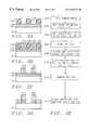
- FIG. 3A step 304depositing a barrier metal layer 220 over the Aluminum layer 230 ; the barrier metal layer of a material selected from the group consisting of TiW, TiN, MoN, WN, and TaN;
- FIG. 3 Bstep 306 , polishing the barrier layer 230 to roughen the surface of the barrier layer
- step 308Patterning the aluminum layer 220 and the barrier metal layer 230 ;
- FIG. 3D step 310pickling the surface of the barrier layer using an HF based pickling solution
- FIG. 3D step 310activating the surface of the barrier layer using a PdCl 2 activation solution comprised of: PdCl2 at a concentration between about 0.1 and 0.2 g/l, HF at a concentration between about 200 and 300 g/l, and acetic acid at a concentration between about 450 and 500 g/l;
- FIG. 3 Dstep 312 —electroless depositing a metal layer 240 over the barrier layer 230 ;
- FIG. 3 EStep 314 —depositing a Solder bump 250 over the electroless metal layer 240 ; the solder bump is composed of Pb—Sn.
- the inventionprovides the following benefits:
- the Three embodimentsprovide electroless depositing process for depositing Cu, Ni or Pd over ⁇ circle around (1) ⁇ PdSix, ⁇ circle around (2) ⁇ Polysilicon, Al, or Ti and ⁇ circle around (3) ⁇ over a chemical-mechanical polished roughen metal layer.
- FIGS. 1A through 1Eare cross sectional view for illustrating the 1st embodiment of the invention for forming a wire using electroless deposition.
- FIG. 1Fis a flow chart of the process of the 1st embodiment of the invention for forming a wire using electroless deposition.
- FIGS. 2A through 2Dare cross sectional view for explaining the 2nd embodiment of the invention for forming a wire using electroless deposition.
- FIG. 2Eis a flow chart of the process of the 2nd embodiment of the invention for forming a wire using electroless deposition.
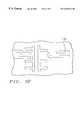
- FIG. 2Fis a top plan view for illustrating the 1st and 2nd embodiments of the invention for forming a wire using electroless deposition.
- FIGS. 3A through 3Eare cross sectional view for explaining the 3rd embodiment of the invention for forming a solder bump using electroless deposition.
- FIG. 3Fis a flow chart of the process of the 3rd embodiment of the invention for forming a solder bump using electroless deposition.
- the present inventionprovides a method of forming metal lines and bumps.
- step 100-FIG. 1Aproviding a semiconductor structure 10; step 102-FIG. 1A- forming barrier layer 20 over the semiconductor structure 10;
- the barrier layeris deposited by Physical Vapor Deposition (PVD) or CVD process the barrier metal layer 20 composed of TiW, TiN, MoN, WN, or TaN;
- Step 104form an Adhesion layer 30 over the Barrier metal layer 20, the adhesion layer composed of Polysilicon;
- a key feature of the electroless bathis the use of NaH 2 PO 2 (Sodium hypophosphite) as the reducing agent.
- Step 108is important 108 1C PdSix is a superior catalytic material for electroless deposition *the PdSi x 50 is not activated by any process (e.g., activating solution, ion implant etc.) 108 1C
- the salicidation anneal temperature (step 108)is low and reaction can proceed in a oxygen atmosphere 114 1E Electroless Pd, Cu or Ni can selectively deposit on PdSix layer 50
- FIGS. 1A to 1 E and 1 FThe first embodiment to form an interconnect is shown in FIGS. 1A to 1 E and 1 F.
- a semiconductor structure 10is provided.
- the semiconductor structurecan comprise a semiconductor substrate having devices formed therein and thereover, including, but not limited to conductive and insulating layers and regions.
- a barrier metal layer 20is deposited over the semiconductor structure 10 as shown in FIG. 1 A.
- the barrier metal layercan be composed of TiW, TiN, MoN, WN or TaN and is preferably composed of TiW, TiN or MoN.
- the barrier layer 20can be formed by Physical Vapor Deposition (PVD) or CVD and preferably has a thickness in a range of between about 300 and 500 ⁇ .
- the next step, ( 104 )involves the deposition of the Polysilicon adhesion layer 30 preferably by LPCVD.
- the layerpreferably has a thickness in a range of 1500 ⁇ +/ ⁇ 20% and more preferably between 1400 and 1600 ⁇ .
- FIG. 1Ashows the resultant structure.
- Step 106involves Sputtering Palladium (Pd) 40 over Polysilicon layer 30 .
- the Palladium layer 40preferably has a thickness in a range of between about 2000 and 2500 ⁇ .
- FIG. 1Cshows the resultant structure.
- the Palladium (Pd) layer 40is annealed to form a Palladium silicide (PdSix) layer 50 .
- FIG. 1Dshows the resultant structure.
- Step 110Pattern PdSix
- Step 110patterns the Palladium (Pd) silicide ( PdSi x ) layer 50 by a photolithographic and etch process.
- a photoresist layeris formed, exposed and developed (not shown).
- a dry Etchis used to remove unwanted PdSi x through the openings in the photoresist layer.
- Step 110also include removing the photoresist used to pattern the PdSix layer 50 .
- Step 112Dry Etch of Barrier Layer
- Step 112Dry etches the barrier layer 20 using the PdSix layer 50 as an etch mask.
- Step 114Electroless Deposition of Metal Layer 60
- step 114involves the electroless deposition of metal layer 60 .
- the metal layercan be Pd, Cu or Ni.
- the processesare described in the tables below.
- the waferis preferably immersed in the electroless baths shown below.
- This Pd electroless deposition processis unique to the invention and is important to the process.
- the use of NaH 2 PO 2 as a reducing agentprovides superior electroless deposition why eliminating unsafe alternative reducing agents.
- Embodiment 2Selective Electroless Depositing using Al, Ti Or Poly Adhesion Layer 130
- the second embodiment that forms an interconnectis shown in FIGS. 2A to 2 D and 2 E.
- the 2nd embodimentis a process to Selective Electroless Depositing Using Al, Ti or Poly adhesion Layer 130 (or seed layer) to form a metal line or interconnect.
- FIG. Reason stepis important 204 2A using Poly, Al or Ti as adhesion layer 130 (Seed layer) for electroless dep.
- adhesion layer 130Seed layer
- a semiconductor structure 10is provided.
- the semiconductor structurecan comprise a semiconductor substrate having devices formed therein and thereover, including, but not limited to conductive and insulating layers and regions.
- FIG. 2Ashows step 202 , the Barrier metal layer deposition 120 over the structure.
- the barrier metal layercan be composed of TiW, MoN, WN, TiN, or TaN, and is most preferably composed of TiW, TiN, or MoN.
- the barrier metal layerpreferably has a thickness in a range of between about 300 and 500 ⁇ .
- the barrier layercan be formed using a Physical Vapor Deposition (PVD) or chemical vapor deposition process.
- FIG. 2Ashows the results of the Adhesion layer 130 deposition.
- the adhesion layeris preferably composed of (a) Poly Si (b) Al or (c) Ti.
- the composition of the adhesion layer (Poly, Al or Ti)is a key unique feature of the invention.
- the adhesion layerpreferably has a thickness in a range of between about 1000 and 2000 ⁇ .
- a photoresist (PR) layer 132is formed over the adhesion layer 132 .
- Step 208the adhesion layer 130 is exposed in the openings of the photoresist layer 132 is cleaned.
- the pickling and activating (and cleaning) processdepends on the composition of the adhesion layer.
- the table belowshows the preferred cleaning processes. Pickling refers to the dipping of a wafer into a pickling solution having composition described in a table below.
- the target valuehas limits +/1 10%.
- Step 210Electroless Deposition of Ni, Cu, or Pd
- FIG. 2Bshows step 208 , the electroless deposition of Ni, Cu, or Pd.
- the deposition processis the same all three of the adhesion layers (poly, Ti, Al) These processes key unique features of the invention.
- Step 210Electroless Deposition of Ni Over the Adhesion Layer 130
- Niis electroless deposited over the Polysilicon adhesion layer.
- a nickel layer 140is deposited by electroless deposition.
- the Niis selectively electroless deposited onto the surface of the polysilicon layer forming a Ni layer over the polysilicon layer 130 using the Pd particles as a catalyst.
- the selectively electroless deposition of Nickelis preferably performed using the four solutions/conditions.
- the four different solutionsform different compositions of the electroless Ni deposited as shown in the table below.
- the selectively electroless deposition of Niis preferably performed at the using the 4 solutions/conditions shown below in the tables.
- composition of the Ni-P solution(1) The composition of the Ni solution Low limit tgt/units high limit Nickel sulfate 25 30 g/L 35 Sodium hypophosphite 6.5 7.5 g/l 10 Ammonium Chloride 6 8.0 g/L 10 Ethylene diamine-complexing 50 60 g/L 70 agent Temperature 70 72° C. 75 pH 9.8 10 10.2
- composition of the Ni-B solution(2) The composition of the Ni solution Low limit tgt/units high limit Nickel sulfate 25 30 g/L 35 Dimethylamine borane 2.5 3.0 g/L 3.5 latic acid-complexing agent 20 25.0 g/L 30 Citric acid-complexing agent 20 25.0 g/L 30 Ammonium chloride 20 30 g/L 40 Thiourea-increases brightness of 0.8 1 mg/L 1.2 resulting Ni coating Temperature 56 60° C 65 pH 5.8 6 6.2
- composition of the Ni-P solution(3) The composition of the Ni-P solution Low limit tgt/units high limit Nickel sulfate 26 28 g/L 30 Sodium citrate 55 60 g/l 65 Ammonium sulfate 60 65 g/l 70 Sodium hypophosphite 16 17 g/l 18 pH 8.5 9.1 9.5
- composition of the Ni-P solution(4) The composition of the Ni-P solution Low limit tgt/units high limit Nickel chloride 20 25 g/l 30 Sodium hypophosphite 25 27 g/l 30 sodium succinate hypophosphite 12 16 g/l 20 pH 4.3 4.6 5.0
- Ni electroless deposition processes of the inventionare suitable for different reducing agents (P or B) and different reducing agent content (low Phosphorous, medium Phosphorus and high phosphorous).
- Step 210(Option B)—Electroless Dep of Cu Layer 140 Over the Adhesion Layer
- step 210 Bselective Electroless deposits Cu over the adhesion layer 130 using the process shown in the table below.
- Step 210(Option C)—Electroless Dep of Pd Layer 140 Over the Adhesion Layer 130
- Step 210 Cinvolves the Electroless deposition of the Pd layer 140 over the adhesion layer 130 using the process in the table below.
- This Pd electroless deposition processis unique to the invention and is important to the process.
- FIG. 2Cshows the removal of the photoresist layer 132 .
- the photoresist layeris preferably removed using O 2 ashing.
- FIG. 2Dshows a dry etch to remove adhesion layer and barrier layer exposed between the electroless metal layer 140 .
- FIG. 2Fshows a top down view of a interconnect or metal line 140 formed by the first or second embodiments of the invention.
- Embodiment 3solder Bump—Polish to Roughen Barrier Layer
- the third embodimentuses a metal barrier layer, activated by CMP, to electroless deposit a Cu, Ni or Pd layer and then form a Pb—Sn bump thereover.
- the third embodiment of the inventionforms a solder bump as shown in FIGS. 3A to 3 D and flow chart FIG. 3 F.
- FIG. Reason stepis novel 306 3B using chemical-mechanical polish to roughen and activate the surface 314 3E using electroless deposited layer 240 as an adhesion layer for the solder bump 250.
- FIG. 3A-stepdepositing an Aluminum layer 220 over the semiconductor structure 10; 302, FIG. 3A step depositing a barrier metal layer 230 over the Aluminum layer 220; the barrier 304,- metal layer is composed of TiW, TiN, MoN, WN, or TaN; FIG. 3B-step polishing the barrier layer 230 to roughen the surface of the barrier layer; the 306, polishing comprises using a Slurry of 0.3 ⁇ M Al2O 3 powder at a Speed of about 300 RPM (+/ ⁇ 10%); FIG. 3C-8- Patterning the aluminum layer 220 and the barrier metal layer 230; FIG.
- 3D-step pickling the surface of the barrier layer using an HF based pickling solution310- FIG. 3D step activating the surface of the barrier layer using a PdCl 2 activation solution 310- comprised of: PdCl2 at a concentration between about 0.1 and 0.2 g/l, HF at a concentration between about 200 and 300 g/l, and acetic acid at a concentration between about 450 and 500 g/l;
- a semiconductor structure 10is provided.
- the semiconductor structurecan comprise a semiconductor substrate having devices formed therein and thereover, including, but not limited to conductive and insulating layers and regions.
- FIG. 3Ashows step 302 , the deposition of the Aluminum layer 230 .
- the Al layer 230is formed as shown in the table below.
- the aluminum layer 230can be composed of Al or Al—Si or Al—Si—Cu alloy.
- Step 304Barrier Metal Deposition
- FIG. 3Ashows the results of step 304 , the deposition of the barrier metal layer 230 .
- the barrier metal layercan be composed of TiW, TiN, MoN, WN, or TaN.
- the barrier metal layerpreferably had a thickness in a range of between about 1000 and 1400 ⁇ .
- Step 306CMP or Polish
- FIG. 3Bshows step 306 , the chemical-mechanical polish (CMP) or polish process which designed to roughen the surface of the barrier layer 230 .
- This stepis critical in improving the activation step (see step 306 ).
- the polish processpreferably comprises a grinding using Slurry of 0.3 ⁇ m Al 2 O 3 powder and at a Speed of about 300 RPM (+/ ⁇ 10%).
- Step 306Activity Step—(Optional)
- the adhesion layeris activated (optional—can be performer after patterning step 308 ) using the following two step process comprising: ⁇ circle around (1) ⁇ —a pickling solution based on HF, and ⁇ circle around (2) ⁇ activation process—activation solution—comprising: PdCl2 0.1 to 0.2 g/l, HF 200 to 300 g/l and acetic acid 450-500 g/l.
- activation solutioncomprising: PdCl2 0.1 to 0.2 g/l, HF 200 to 300 g/l and acetic acid 450-500 g/l.
- This activation step in combination with CMP step 306is important for the electroless deposition step 312 .
- FIG. 3Cshows step 308 , the patterning of the Al layer 220 and the barrier layer 230
- the patterningcomprises forming a photoresist layer with opening over the barrier layer and dry etching the Al and barrier layers.
- FIG. 3D step 310shows the second activation of the barrier layer using a activation solution.
- the preferred activation solutionis shown below.
- Step 312Electroless Deposition of Metal 240 on the CMP Roughened Barrier Layer 230
- Step 312shows the Electroless deposition of a metal layer 240 composed of Cu, or Ni or Pd.
- the selective electroless depositing process for Cu, Ni and Pd,is preformed as described above in the second embodiment.
- the metal layer 240 composed of Cuis preferably formed by a two step process comprising ⁇ circle around (1) ⁇ a Physical Vapor Deposition (PVD) (Sputtering) forming a Cu seed layer (not shown) with a thickness of about 500 ⁇ over the barrier layer 230 and then ⁇ circle around (2) ⁇ electroplating or electroless depositing Cu over the Cu (PVD) seed layer.
- PVDPhysical Vapor Deposition
- FIG. 3Eshows the Solder bump deposition 250 over the metal layer 240 .
- the solder bump 250is preferably compose of lead-tin alloy and preferably has a thickness in a range of between about 25 and 50 ⁇ m.
- the solder bumpis about 100 ⁇ m wide on etch side.
- the inventionhas 3 preferred embodiments.
- the first embodimentforms metal lines or interconnects.
- the key features/steps of the first embodimentare: step 108 —PdSix layer 50
- the table belowindicates the key steps and their importance.
- Step FIG. Reason stepis important 108 1c PdSix layer 50 is superior catalytic material for electroless deposition The salicidation temperature is low and reaction can proceed in a oxygen atmosphere 114 1E Electroless Cu or Ni can selectively deposit on PdSix
- the 1st embodimentsolves the problems of: forming the silicide layer on the surface of refractory metal or contact hole and then the electroless plating can easily selectively deposited metal on the exposed PdSix region.
- the second embodimentforms another metal line.
- the key features/steps of the second embodimentare:
- Step FIG. Reason stepis important 204 2A using Poly, Al or Ti as adhesion layer 130 208 & 2B pretreatment of the surface of the Poly Al, or Ti adhesion 210 layer 130 for electroless dep-includes pickling and activating.
- the second embodiments using Al, Poly or Ti material as a seed material,(Adhesion layer 130 ).
- the metalis selectively electroless deposited over the adhesion layer. Also important is the pickeling and activating or zincating process.
- the 2nd embodimentis very simple and compatible with conventional IC processing.
- the third embodimentforms a solder bump.
- the key features/steps of the third embodimentare: ⁇ circle around (1) ⁇ chemical-mechanical polish of the refectory metal layer 230 (FIG. 3B, step 306 ) in order to increase absorption.
- the electroless Ni deposited or Cuhas a superior solderable property.
- the processsave one mask step, since the selective metal deposition 312 makes it unnecessary to form a mask.
Landscapes
- Chemical & Material Sciences (AREA)
- Engineering & Computer Science (AREA)
- Microelectronics & Electronic Packaging (AREA)
- Manufacturing & Machinery (AREA)
- Computer Hardware Design (AREA)
- Power Engineering (AREA)
- Metallurgy (AREA)
- General Chemical & Material Sciences (AREA)
- Chemical Kinetics & Catalysis (AREA)
- Materials Engineering (AREA)
- Mechanical Engineering (AREA)
- Organic Chemistry (AREA)
- General Physics & Mathematics (AREA)
- Condensed Matter Physics & Semiconductors (AREA)
- Physics & Mathematics (AREA)
- Chemically Coating (AREA)
- Internal Circuitry In Semiconductor Integrated Circuit Devices (AREA)
Abstract
Description
1) Field of the Invention
The present invention relates to electroless plating and more particularly to the electroless plating of Cu and Ni in semiconductor wires and bumps. It also relates to the formation of high-resolution conductive wiring patterns on semiconductor and advanced packaging substrates.
2) Description of the Prior Art
Electroless plating is a method used to deposit a thin film or a layer of some material on a substrate. The principal step is the immersion of the substrate in a plating bath containing ions of the material to be deposited, causing some of these ions to precipitate at the substrate's surface. Unlike electroplating methods, electroless plating does not require an externally applied electric field to facilitate the ion deposition process. The electroless plating may be selective, i.e., the deposition may occur only at locations that exhibit appropriate electrochemical properties. For example, the ions may be deposited mainly on those portions of the substrate that are made of a material identical (or exhibiting affinity) to the material being deposited. Another of many possibilities is that portions of the substrate may be treated or activated with a catalyst to cause the ion deposition to occur at a rapid rate. The material or catalyst present in the selected areas before the deposition is sometimes referred to as “seed material” or “seed layer”. The ratio of the deposition rate on the activated regions to the deposition rate at the non-activated regions is referred to as the “plating process selectivity”. The deposition rate may also depend on the physical characteristics of the activated areas, e.g., their sizes, aspect ratios, and distances separating them. If the thickness of the material deposited in various locations at the substrate is similar, the plating process is said to be uniform. For many applications, it is crucial that the plating process be uniform, that it exhibit high selectivity, and that the deposited film strongly adheres to the substrate.
One of the ways to increase the adhesion is to subject the plated artifact to an annealing process. The conditions or process parameters such as the temperature, ion concentration in the plating path, and duration of the bath, which provide desirable uniformity, selectivity, and some physical properties of the deposited layer usually fall within certain ranges, the combination of which is called a “technological process window”. To insure the repeatability and consistency of the plating process, it is desirable that the process window be as large as possible.
Electroless plating of solid metals from a solution containing metal ions onto a catalytically active surface has been widely used in the printed circuit board industry for production of wiring layers and inter-layer (via) connections. More recently, this body of knowledge has been applied to producing metal interconnect films in the integrated circuit (IC) industry. The electroless plating technique has several advantages over other well known metal deposition techniques such as sputtering and evaporation. One advantage is that the electroless plating process uses materials and capital equipment that are inexpensive compared to the other methods. Another advantage is that the technique deposits films only in selected, catalytically active regions. This property of selective growth allows the user to reduce the number of lithographic patterning and etching steps used to define the regions to be covered by the deposited metal. It also facilitates dense patterning of materials such as copper, that are difficult to etch anisotropically. Yet another advantage is that the growth rate of the deposited metal is relatively independent of the angles or relative heights of topographic features on the substrate being plated. This property enables deposition into features having high aspect ratios, such as deep via holes on multi-layer circuit boards, that could not be uniformly covered by the “line of sight” deposition techniques such as sputtering and evaporation.
The most commonly published use of electroless plating in the integrated circuit industry is for filling contact or via holes. The traditional contact is a hole, pattemed and etched in a dielectric film placed on top of a conducting film so that the surface of the conducting film is exposed within the hole. An upper level of conductor, patterned over the contact hole, makes a physical and electrical contact with the lower conductor in the contact region. Electroless plating has been used to grow metal selectively onto the surface of the lower conductor that is exposed in the contact hole. This produces a metallic “plug” which electrically couples the upper conductor to the lower conductor. The “plug” is plated until its top surface substantially coincides with the top surface of the dielectric, and the resulting planarity of the structure prevents problems that might occur in the subsequent processing if topographic variations were present in the vicinity of the contact region.
Although electroless plating-based processes, such as contact-hole filling, offer many advantages to the process designer, the technique has only found limited acceptance within the IC manufacturing community. Although the technique appears to be relatively simple, the chemical reactions occurring at the plated surface can be complex. Some of the factors inhibiting the wider application of electroless plating are the difficulties in controlling the plating process and in obtaining uniform plating thickness on the entire substrate, as well as the sensitivity to contaminants exhibited by the process. Many of these problems are related to the previously known surface activation techniques, i.e., methods used to render the plated surface catalytically active. The present invention teaches a new surface preparation technique that provides a more active surface on which to plate, thereby improving the latitude of the plating process and the uniformity of the plated materials.
Many surface activation techniques have been reported in both the patent and scientific literature. Frequently, these techniques are designed for plating a specific material onto a specific substrate material, and rely on certain properties of these materials. The most common applications of electroless plating to integrated circuit manufacturing comprise plating of nickel, cobalt, palladium, or copper onto one of two types of substrate surfaces. The first type of substrate surface comprises conductive regions of substrates that are generally formed of silicon, aluminum, or aluminum alloys. The second type of substrate comprises a non-conductor such as silicon dioxide or a polymeric insulator. The reported surface activation techniques applied to these substrates usually fall into one of three categories: (1) catalyst film deposition by evaporation or sputtering, (2) catalyst film deposition by electrochemical surface modification, and (3) catalytic film deposition from a colloidal suspension.
Palladium and platinum are frequently used as catalytic surface activators in electroless plating methods. Catalytic films of palladium or platinum for subsequent electroless plating can be readily deposited by evaporation or sputtering techniques. The films deposited with these techniques can be patterned by well known lithographic techniques, e.g., subtractive etching or liftoff. Large features and/or dense patterns of small features are relatively easy to plate with this method.
It has been reported that the catalytic activity of palladium films deposited by evaporation and sputtering is lower than that of palladium films deposited by other techniques, for example electrochemically deposited films. This low activity has a significant detrimental impact on the uniformity of structures formed by this process and on the resulting yield. Features that are small or separated with large distances from other features are significantly more difficult to plate. These size-dependent and proximity-dependent effects are often related to the presence of stabilizing agents (stabilizers) in the plating solutions. Stabilizers are added to most commercially available plating solutions to prevent the spontaneous decomposition of the plating bath. Generally, the stabilizers reduce or even prevent the auto-catalytic plating reaction from occurring on small particles that may be present in the bath. The presence of such particles may result from a contamination of the plating bath with the airborne dust. The stabilizing agents also exert a significant and beneficial impact on the electrical and mechanical properties of the deposited film, although the mechanisms for this action are not always clearly understood. It is intuitively clear, however, that any mechanism that prevents undesirable auto-catalytic plating on small particles in the bath may also impede the desirable plating of small, isolated features present on the substrate. Plating of small features may be enhanced by modifying the bath composition or process conditions. For instance, the ability to plate sub-micrometer features can be improved by raising the plating bath temperature, or by reducing the amount of the stabilizing agents in the bath. This improvement is obtained the price of a reduced plating selectivity and reduced bath stability.
The plating non-uniformity and process selectivity also depend on the detailed history of the catalytic surface. Subjecting this surface to any post-patterning clean-up processes or exposing it to air before plating reduce the ability to uniformity plate the desired features.
A wide range of electrochemical surface modification techniques to enable the catalytic plating on metallic and dielectric materials have been disclosed. Aluminum films used in VLSI circuits can be rendered catalytically active by electroless plating of a seed layer of palladium from a bath containing a dilute aqueous solution of PdCl2and HCl. Typically, the pre-existing aluminum oxide is removed by a short immersion in a dilute HF solution prior to the palladium activation. The degree of activation achieved by this technique depends strongly on the processing history of the aluminum surface, the concentration of the activator components, the temperature, and duration of the exposure of the aluminum surface of the activator. This method can achieve very high levels of activation, but suffers from a very small “process window”. If the exposure to the activator solution is too brief, the insufficient surface activation and the resulting plating non-uniformity will occur. If the exposure to the activator solution is too long, the plated metal will exhibit poor adhesion. While this process has been demonstrated to work, the development of a stable, reproducible manufacturing implementation is difficult.
Another method of activating aluminum surfaces using the electroless deposition of zinc. The zinc is then used as a catalytic seed material for subsequent plating of the nickel film. This process is commonly refereed to as “zincating”, and is extremely effective for activating larger dimension patterns but suffers from a reduced process window in the presence of features with small dimensions, such as used in many integrated circuits. The process exhibits a tradeoff between activation and adhesion similar to the one discussed above for palladium-based activation.
Conventionally, the conductor lines are formed by photolithography and dry etching of dielectric and metal layers. However, the Al—Si (or Al—Si—Cu) system does not satisfy many requirements, such as high thermal stability, low electromigration, and high corrosion resistance. Copper is a candidate for multilevel interconnection because of several properties that give it the potential advantages over Al. Unfortunately, copper is quite mobile in Si at elevated temperature and its presence in Si creates trap levels that are deleterious to device operation. For these reasons, it is necessary to determine which materials may act as effective diffusion barrier for copper migration. A suitable diffusion barrier should meet certain constrains:
a. slow transport rate of the substrate and the adjoining material across the barrier layer;
b. slow loss rate of barrier layer into the substrate and adjoining layer;
c. strong adhesion of barrier layer with substrate and with adjoining material;
d. the barrier layer should be laterally uniform in thickness and substrate;
e. the barrier layer should be thermodynamically stable against substrate and adjoining material;
f. the barrier layer should have low resistivity.
Electroless copper deposition technique is especially appealing because of low cost and low process temperature, high deposition rate and high quality of electroless Cu deposit. Electroless copper process can be described by two steps which occur simultaneously on the catalytic surface: 1) anodic oxidation of reducing agents and 2) cathodic reduction of metal ions. A catalytic layer is needed for electroless copper deposition to catalyze oxidation of reducing agents and to transport electrons from anodic sites of reaction to cathodic sites of reaction. Hence we must deposit another adhesion layer on the diffusion barrier layer because the surface of diffusion barrier is not autocatalytic.
The importance of overcoming the various deficiencies noted above is evidenced by the extensive technological development directed to the subject, as documented by the relevant patent and technical literature. The closest and apparently more relevant technical developments in the patent literature can be gleaned by considering U.S. Pat. No. 5,183,795(Ting):Fully planar metalization process—that teaches planar interconnect using selective, electroless deposition of a metal such as copper into interconnect channels. Channels are formed in the dielectric layers by patterning and etching the composite dielectric layers. Silicon atoms are implanted in the bottom of the interconnect channels and then the metal layer is selectively, electrolessly deposited to fill the channels in the first dielectric film, thus forming a level of interconnect.
U.S. Pat. No. 5,429,994 (Ishikawa):Wiring forming method, wring restoring method and wiring pattern changing method—shows a low-resistance metal layer is formed on the metal film by electroless plating.
U.S. Pat. No. 5,580,668(Kellam):Aluminum-palladium alloy for initiation of electroless plating—shows thin layers of aluminum (13) and palladium (12) that are deposited and annealed to produce aluminum-palladium alloy (14). The surface of the alloy (14) is exposed and treated with an aluminum etchant to produce a catalytic surface (15). The catalytic surface is used for electroless plating of nickel.
U.S. Pat. No. 4,182,781(Hooper):Low cost method for forming elevated metal bumps on integrated circuit bodies employing an aluminum/palladium metallization base for electroless plating—shows Elevated metal contact bumps provided on a microelectronic semiconductor circuit, with the use of aluminum-palladium metallization as a base for selective electroless plating. The aluminum-palladium film is then patterned in a single step, using an etchant which attacks both metals at substantially the same rate. The metal pattern is then covered with an insulation layer wherein apertures are opened to expose palladium at selected sites for immersion in an electroless plating bath of ionic Cu or Ni for bump formation.
U.S. Pat. No. 5,169,680 (Ting):Electroless deposition for IC fabrication—shows electroless deposition provides a selective and an additive process for forming conductive layers, filling window and providing interconnections and terminals. The conducting material is selectively deposited on a catalytic underlying surface. When the underlying surface is not catalytic, an activation step is used to cause the surface to be catalytic.
U.S. Pat. No. 4,954,214(Ho) shows an interconnect structure using Ni deposited by electroless deposition using a refractory metal seed layer.
Dubin, et al.,Selective Electroless Ni Deposition On A Tiw Underlayer For Integrated Circuit Fabrication,Thin Solid Films, 226 (1993) pp. 87-93, discusses Ni electroless deposition on TiW layers.
It is an object of the present invention to provide a method for fabricating devices by Electroless Plating of {circle around (1)} Ni, Pd or Cu {circle around (2)} on a Nitride barrier layer.
It is an object of the present invention to provide a method for fabricating devices by Electroless Plating of {circle around (1)} Ni or Cu {circle around (2)} on Poly, or Al on adhesion layers which are deposited on TiN barrier layers.
It is an object of the present invention to provide a method for fabricating interconnections using Electroless Plating of Ni or Cu over a Pd silicide activation layer.
It is an object of the present invention to provide a method for fabricating devices by solder bumps using Electroless Plating of Cu for a solder bump.
It is an objective of the present invention to provide metal line formed by a selective electroless deposition process using Palladium Silicide (PdSix) a seed layer (e.g., Al, Ti or poly) or chemical-mechanical polish.
The invention provides three embodiments for electroless deposition.
The 1st embodiment uses a PdSix seed layer for electroless deposition of Cu, Ni, or Pd to form an interconnect.
The second embodiment uses a polysilicon, Ti or Al adhesion layer to electroless deposit Cu, Pd or Ni to form an interconnection.
The third embodiment uses a metal barrier layer, activated by CMP, to electroless deposit a Cu, Ni or Pd layer and then form a Pb—Sn bump thereover.
1st Embodiment—PdSix Seed Layer for Electroles s Deposition
The first embodiment for a method for forming an interconnect by depositing selectively by electroless deposition ametal 60 using a palladiumsilicide seed layer 60 can be summarized as follows:
(a)step 100—FIG. 1A providing asemiconductor structure 10;
(b)step 102—FIG.1A—forming abarrier layer 20 over thesemiconductor structure 10; the barrier metal layer is composed of TiW, TN, MoN, WN, or TaN;
(c)Step 104—forming anAdhesion layer 30 over theBarrier metal layer 20, the adhesion layer composed of Polysilicon;
(d)step 106—FIG.1B—sputter depositing a Palladium (Pd)layer 40 over theAdhesion layer 30;
(e)step 108 FIG.1C—Annealing the Palladium (Pd)layer 40 to form a Palladium (Pd)Silicide layer 50;
(e-1) the anneal to form the palladium silicide layer is performed at a temp between about 230 and 270° C. for a time between about 20 to 40 minutes; the anneal is performed in an ambient of N2and air;
(f)step 110—FIG.1D—patterning thePalladium silicide layer 50 to form Palladiumsilicide interconnect patterns 50;
(g)step 112—FIG.1D—patterning thebarrier layer 20 using the Palladiumsilicide line patterns 50 as an etch mask forming barrier layer interconnect patterns;
(h)step 114—FIG.1E—selectively electroless depositing ametal layer 60 on the Palladiumsilicide line patterns 50 to form an interconnect; the metal layer composed of a material selected from the group consisting of Ni, Cu, and Palladium (Pd) over the Palladium silicide interconnect patterns whereby the metal layer was deposited without activating the palladium silicide line.
2nd Embodiment—Electroless Depositing aMetal 140 OverAdhesion Layer 130 of Polysilicon, Al or Ti
The Second embodiment provides a method of forming a metal line using an electroless deposition of Cu or Ni over anadhesion layer 130 composed of Polysilicon, Al, or Ti, comprising
(a) FIG.2F—Step200—providing asemiconductor structure 10;
(b)step 200—depositing aBarrier metal layer 120 over thesemiconductor structure 10;
(e1) the barrier metal layer of a TiW, TN, MoN, WN, or TaN;
(c) FIG.2A—step 204—depositing anAdhesion layer 130 over theBarrier metal layer 120, theadhesion layer 130 composed of a material selected from the group consisting of (a) Poly Si (b) Al and (c) Ti;
(d)step 206—forming aphotoresist pattern 132 over theadhesion layer 130;
(e)step 208—pickling and activating theadhesion layer 130;
(f)step 210—electrolessly depositing ametal layer 140 over the adhesion layer, themetal layer 140 composed of a material selected from the group consisting of Cu, Pd and Ni,
(g) FIG.2C—step 212—removing thephotoresist layer 132 thereby exposing portions of the adhesion layer; and
(h) FIG.2D—step 214—Dry etching the exposed portion of theadhesion layer 130 and thebarrier layer 120; thereby forming ametal line 140130120.
3rd Embodiment—Electroless Deposition on a Metal Barrier Layer that is Roughed by CMP
The third embodiment (See FIG. 3) teaches a method of forming a solder bump using an electroless metal deposition over an adhesion layer that is roughened by a polishing process comprising:
(a) FIG.3—Step300—providing asemiconductor structure 10;
(b) FIG.3A—step 302, depositing anAluminum layer 220 over thesemiconductor structure 10;
(c) FIG.3A step 304—depositing abarrier metal layer 220 over theAluminum layer 230; the barrier metal layer of a material selected from the group consisting of TiW, TiN, MoN, WN, and TaN;
(d) FIG.3B—step 306, polishing thebarrier layer 230 to roughen the surface of the barrier layer;
(e)step 308—Patterning thealuminum layer 220 and thebarrier metal layer 230;
(f) FIG.3D step 310—pickling the surface of the barrier layer using an HF based pickling solution;
(g) FIG.3D step 310—activating the surface of the barrier layer using a PdCl2activation solution comprised of: PdCl2 at a concentration between about 0.1 and 0.2 g/l, HF at a concentration between about 200 and 300 g/l, and acetic acid at a concentration between about 450 and 500 g/l;
(h) FIG.3D—step312—electroless depositing ametal layer 240 over thebarrier layer 230;
(i) FIG.3E—Step314—depositing aSolder bump 250 over theelectroless metal layer 240; the solder bump is composed of Pb—Sn.
The invention provides the following benefits:
The Three embodiments provide electroless depositing process for depositing Cu, Ni or Pd over {circle around (1)} PdSix, {circle around (2)} Polysilicon, Al, or Ti and {circle around (3)} over a chemical-mechanical polished roughen metal layer.
less costly than other selective metal deposition processes.
More reproducible technique than prior art processes.
lower process temperature, high deposition rate and higher quality than prior art.
Additional objects and advantages of the invention will be set forth in the description that follows, and in part will be obvious from the description, or may be learned by practice of the invention. The objects and advantages of the invention may be realized and obtained by means of instrumentalities and combinations particularly pointed out in the append claims.
The features and advantages of a semiconductor device according to the present invention and further details of a process of fabricating such a semiconductor device in accordance with the present invention will be more clearly understood from the following description taken in conjunction with the accompanying drawings in which like reference numerals designate similar or corresponding elements, regions and portions and in which:
FIGS. 1A through 1E are cross sectional view for illustrating the 1st embodiment of the invention for forming a wire using electroless deposition.
FIG. 1F is a flow chart of the process of the 1st embodiment of the invention for forming a wire using electroless deposition.
FIGS. 2A through 2D are cross sectional view for explaining the 2nd embodiment of the invention for forming a wire using electroless deposition.
FIG. 2E is a flow chart of the process of the 2nd embodiment of the invention for forming a wire using electroless deposition.
FIG. 2F is a top plan view for illustrating the 1st and 2nd embodiments of the invention for forming a wire using electroless deposition.
FIGS. 3A through 3E are cross sectional view for explaining the 3rd embodiment of the invention for forming a solder bump using electroless deposition.
FIG. 3F is a flow chart of the process of the 3rd embodiment of the invention for forming a solder bump using electroless deposition.
The present invention will be described in detail with reference to the accompanying drawings. The present invention provides a method of forming metal lines and bumps.
In the following description numerous specific details are set forth such as flow rates, pressure settings, thicknesses, etc., in order to provide a more thorough understanding of the present invention. It will be obvious, however, to one skilled in the art that the present invention may be practiced without these details. In other instances, well know process have not be described in detail in order to not unnecessarily obscure the present invention.
It should be recognized that many publications describe the details of common techniques used in the fabrication process of integrated circuit components. See, E.g., C. Y. Chang, S. M. Sze, inULSI Technology,by The McGraw-Hill Company, Inc. copyright 1997. Those techniques can be generally employed in the fabrication of the structure of the present invention. Moreover, the individual steps of such a process can be performed using commercially available integrate circuit fabrication machines. As specifically necessary to than understanding of the present invention, exemplary technical data are set forth based upon current technology. Future developments in the art may call for appropriate adjustments as would be obvious to one skilled in the art.
First Embodiment—Interconnect A—FIGS. 1A thru1E,1F
The table below summarizes the steps for the first embodiment.
| TABLE |
| Summary of 1st embodiment |
| First | Metal lines 60 electroless deposited over |
| Embodiment | silicide |
| 50 | |
| Step- | Process |
| step 100-FIG. 1A | providing a |
| step 102-FIG. 1A- | forming |
| barrier layer is deposited by Physical Vapor Deposition (PVD) or CVD | |
| process | |
| the | |
| Step 104 | form an |
| layer composed of Polysilicon; | |
| step 106-FIG. 1B- | sputter Palladium (Pd) |
| Key step-Anneal the | |
| anneal at a temp between about 230 and 270° C. for a time between | |
| about 20 to 40 minutes in N2or air; | |
| step 110-FIG. 1D- | pattern the |
| patterns; | |
| step 112-FIG. 1D | pattern the barrier layer using the Palladium silicide line patterns as an |
| etch mask; | |
| step 114-FIG. 1E- | electroless depositing a |
| from the group consisting of Ni or Cu over the Palladium silicide line | |
| patterns. A key feature of the electroless bath is the use of NaH2PO2 | |
| (Sodium hypophosphite) as the reducing agent. | |
Note that in this invention, all parameters that have only one value (e.g., a target value) have low and high limits inferred as plus or minus 10% of the parameter (+/−10%). This does not mean that the parameter is not important or the process is not sensitive to the variations in the parameter, only that the parameter has a +/−10% limits. This is especially important for the parameters for the electroless baths. This will make the disclosure easier to read.
The table below indicates the key steps and their importance.
| TABLE |
| important elements of the interconnect of the first embodiment |
| Step | FIG. | Reason step is important |
| 108 | 1C | PdSix is a superior catalytic material for electroless |
| deposition *the | ||
| (e.g., activating solution, ion implant etc.) | ||
| 108 | 1C | The salicidation anneal temperature (step 108) is low and |
| reaction can proceed in a | ||
| 114 | 1E | Electroless Pd, Cu or Ni can selectively deposit on |
The first embodiment to form an interconnect is shown in FIGS. 1A to1E and1F.
Asemiconductor structure 10 is provided. The semiconductor structure can comprise a semiconductor substrate having devices formed therein and thereover, including, but not limited to conductive and insulating layers and regions.
Abarrier metal layer 20 is deposited over thesemiconductor structure 10 as shown in FIG.1A. The barrier metal layer can be composed of TiW, TiN, MoN, WN or TaN and is preferably composed of TiW, TiN or MoN. Thebarrier layer 20 can be formed by Physical Vapor Deposition (PVD) or CVD and preferably has a thickness in a range of between about 300 and 500 Å.
The next step, (104) involves the deposition of thePolysilicon adhesion layer 30 preferably by LPCVD. The layer preferably has a thickness in a range of 1500 Å+/−20% and more preferably between 1400 and 1600 Å. FIG. 1A shows the resultant structure.
Step108—Form Palladium Silicide (PdSix)Layer 40
Next, the Palladium (Pd)layer 40 is annealed to form a Palladium silicide (PdSix)layer 50. The anneal is preferably at a temperature between about 230 and 270 (tgt 250° C.) for a time between about 20 and 40 min (tgt =30 min ) in a N2or Air ambient.
A key feature of thePdSix layer 40 is that its surface need not be cleaned or treated before electroless deposition. FIG. 1D shows the resultant structure.
Step110—Pattern PdSix
Step110 also include removing the photoresist used to pattern thePdSix layer 50.
Step112—Dry Etch of Barrier Layer
Step112 Dry etches thebarrier layer 20 using thePdSix layer 50 as an etch mask.
Step114—Electroless Deposition ofMetal Layer 60
Next,step 114 involves the electroless deposition ofmetal layer 60. The metal layer can be Pd, Cu or Ni. The processes are described in the tables below. The wafer is preferably immersed in the electroless baths shown below.
| TABLE |
| Important parameters of bath for electroless Cu deposition over |
| layer |
| 60 |
| Composed of | |||
| Materials | Cu | Low limit | high limit |
| Thickness | Å | 8000 | 9000 |
| Copper sulphate | grams/Liter (g/L) | 5.8 | 6.2 |
| (Copper sulfate) | |||
| sodium citrate | g/l | 14.5 | 15.5 |
| Nickel Sulphate | g/l | 0.45 | 0.55 |
| Sodium | g/l | 10.2 | 11.0 |
| hypophosphite | |||
| TABLE |
| Important parameters of electroless of Ni over |
| Composed of | |||||
| Materials | Ni | Low limit | High limit | ||
| Thickness | Å | 1800 | 2200 | ||
| Nickel Chloride | g/l | 28 | 32 | ||
| sodium | g/l | 7 | 8 | ||
| hypophosphite | |||||
| Sodium Citrate | g/l | 70 | 75 | ||
| ammonium chloride | g/l | 45 | 50 | ||
| pH | 9.1 | 9.3 | |||
| Temp | ° C. | 70 | 75 | ||
| TABLE |
| Electroless Pd solution parameters |
| Chemical | units | low limit | high limit | ||
| PdCl2 | g/L | 3.6 | 4.4 | ||
| NaH2PO2H2O | g/L | 10.5 | 21 | ||
| NaOH | ml/ | 10 | 20 | ||
| pH | 8 | 10 | |||
| Temp | C° | 40 | 50 | ||
This Pd electroless deposition process is unique to the invention and is important to the process. The use of NaH2PO2as a reducing agent provides superior electroless deposition why eliminating unsafe alternative reducing agents.
Embodiment 2—Selective Electroless Depositing using Al, Ti OrPoly Adhesion Layer 130
The second embodiment that forms an interconnect is shown in FIGS. 2A to2D and2E. The 2nd embodiment is a process to Selective Electroless Depositing Using Al, Ti or Poly adhesion Layer130 (or seed layer) to form a metal line or interconnect.
The key steps to the second embodiment are listed below:
| TABLE |
| Key Steps To The 2nd Embodiment |
| Step | FIG. | Reason step is important |
| 204 | 2A | using Poly, Al or Ti as adhesion layer 130 (Seed layer) |
| for electroless dep. | ||
| 208 & | 2b | pretreatment of the surface of the Poly Al, or |
| 210 | ||
| pickling and activating. | ||
Asemiconductor structure 10 is provided. The semiconductor structure can comprise a semiconductor substrate having devices formed therein and thereover, including, but not limited to conductive and insulating layers and regions.
FIG. 2A showsstep 202, the Barriermetal layer deposition 120 over the structure. The barrier metal layer can be composed of TiW, MoN, WN, TiN, or TaN, and is most preferably composed of TiW, TiN, or MoN. The barrier metal layer preferably has a thickness in a range of between about 300 and 500 Å. The barrier layer can be formed using a Physical Vapor Deposition (PVD) or chemical vapor deposition process.
FIG. 2A shows the results of theAdhesion layer 130 deposition. The adhesion layer is preferably composed of (a) Poly Si (b) Al or (c) Ti. The composition of the adhesion layer (Poly, Al or Ti) is a key unique feature of the invention. The adhesion layer preferably has a thickness in a range of between about 1000 and 2000 Å.
Next, instep 206, a photoresist (PR)layer 132 is formed over theadhesion layer 132.
InStep 208, theadhesion layer 130 is exposed in the openings of thephotoresist layer 132 is cleaned. The pickling and activating (and cleaning) process depends on the composition of the adhesion layer. The table below shows the preferred cleaning processes. Pickling refers to the dipping of a wafer into a pickling solution having composition described in a table below.
| TABLE |
| Pickling/ Activate/Clean surfaces of adhesion layer 130 to be electroless NI deposited upon |
| (All values shown in tables have +/− 10% limits) |
| Adhesion | |||
| layer | Poly Si | Al | Ti |
| 2 steps- | |||
| Pickling | {circle around (1)}-a pickling solution | {circle around (1)}-a pickling solution | {circle around (1)}-pickling solution |
| step | based on HF | based on NaOH | based on Nitric acid or |
| HF | |||
| activation | {circle around (2)} activation process- | {circle around (2)}-activating (2 options | {circle around (2)}-activating using Zinc |
| step | activation solution- | (a) and (b) | immersion deposition- |
| PdCl2 0.1 to 0.2 g/l | (a) PdCl2 activation | coats 100 Å of Zn onto | |
| HF 200 to 300 g/l | process- | Ti adhesion layer | |
| acetic acid 450-500 g/l | PdCl2 0.1 to 0.2 g/l | NaOH 120 g/L | |
| HF 200 to 300 g/l | ZnO 10 g/L | ||
| acetic acid 450-500 g/l | C4H4KNaO64 H2O 50 g/l | ||
| NaNO3 1 g/l | |||
| or | |||
| (b) ZINC immersion- | |||
| in a zinc solution | |||
| NaOH 120 G/L (target) | |||
| ZnO 10 g/l | |||
| C4H4KNaO6—4 H2O- | |||
| 50 g/l | |||
| NaNO31 g/l | |||
As with all parameters in this patent that only have one target value (tgt), the target value has limits +/1 10%.
Step210—Electroless Deposition of Ni, Cu, or Pd
FIG. 2B showsstep 208, the electroless deposition of Ni, Cu, or Pd. The deposition process is the same all three of the adhesion layers (poly, Ti, Al) These processes key unique features of the invention.
Step210 Option A—Electroless Deposition of Ni Over theAdhesion Layer 130
Next, Ni is electroless deposited over the Polysilicon adhesion layer. Anickel layer 140 is deposited by electroless deposition. The Ni is selectively electroless deposited onto the surface of the polysilicon layer forming a Ni layer over thepolysilicon layer 130 using the Pd particles as a catalyst. The thickness of electroless Ni film is preferably between about 1800 and 2200 Å. Deposition was conducted in a pH between 9 and 11 (tgt.=10), solution at a temperature between 87 and 93° C. and more preferably about 90° C.
The selectively electroless deposition of Nickel is preferably performed using the four solutions/conditions. The four different solutions form different compositions of the electroless Ni deposited as shown in the table below.
| TABLE |
| The Atomic Percentage Of The Deposited Ni Using The Four Solutions |
| Ni (wt %) | P (wt %) | B (Wt %) | |||
| solution | (+/−1%) | (+/−1%) | (+/−1%) | ||
| 1 | 96 | 4 | 0 | ||
| 2 | 97 | 0 | 3 | ||
| 3 | 93.5 | 6.5 | 0 | ||
| 4 | 91.5 | 8.5 | 0 | ||
The selectively electroless deposition of Ni is preferably performed at the using the 4 solutions/conditions shown below in the tables.
| TABLE |
| The composition of the Ni-P solution (1) |
| The composition of the Ni solution | Low limit | tgt/units | high limit |
| Nickel sulfate | 25 | 30 | g/L | 35 |
| Sodium hypophosphite | 6.5 | 7.5 | g/ | 10 |
| Ammonium Chloride | 6 | 8.0 | g/ | 10 |
| Ethylene diamine-complexing | 50 | 60 | g/L | 70 |
| agent | ||||
| Temperature | 70 | 72° C. | 75 | |
| pH | 9.8 | 10 | 10.2 | |
| TABLE |
| The composition of the Ni-B solution (2) |
| The composition of the Ni solution | Low limit | tgt/units | high limit |
| Nickel sulfate | 25 | 30 g/L | 35 |
| Dimethylamine borane | 2.5 | 3.0 g/L | 3.5 |
| latic acid-complexing | 20 | 25.0 g/ | 30 |
| Citric acid-complexing | 20 | 25.0 g/ | 30 |
| 20 | 30 g/ | 40 | |
| Thiourea-increases brightness of | 0.8 | 1 mg/L | 1.2 |
| resulting Ni coating | |||
| Temperature | 56 | 60° C | 65 |
| pH | 5.8 | 6 | 6.2 |
| TABLE |
| The composition of the Ni-P solution (3) |
| The composition of the Ni-P | |||
| solution | Low limit | tgt/units | high limit |
| Nickel sulfate | 26 | 28 | g/ | 30 |
| Sodium citrate | 55 | 60 | g/l | 65 |
| 60 | 65 | g/l | 70 | |
| Sodium hypophosphite | 16 | 17 | g/l | 18 |
| pH | 8.5 | 9.1 | 9.5 | |
| TABLE |
| The composition of the Ni-P solution (4) |
| The composition of the Ni-P | |||
| solution | Low limit | tgt/units | high |
| Nickel chloride |
| 20 | 25 | g/ | 30 | |
| Sodium hypophosphite | 25 | 27 | g/ | 30 |
| sodium succinate hypophosphite | 12 | 16 | g/ | 20 |
| pH | 4.3 | 4.6 | 5.0 | |
Key points to the Ni electroless deposition processes of the invention are that this process is suitable for different reducing agents (P or B) and different reducing agent content (low Phosphorous, medium Phosphorus and high phosphorous).
Step210(Option B)—Electroless Dep ofCu Layer 140 Over the Adhesion Layer
The deposition of step210B selective Electroless deposits Cu over theadhesion layer 130 using the process shown in the table below.
| TABLE |
| Important parameters of electroless of Cu over |
| Composed of | |||
| Materials | Cu | Low limit | high limit |
| Thickness | Å | 8000 | 9000 |
| Copper sulphate | grams/Liter (g/L) | 5.8 | 6.2 |
| sodium citrate | g/l | 14.5 | 15.5 |
| Nickel Sulphate | g/l | 0.45 | 0.55 |
| Sodium | g/l | 10.2 | 11.0 |
| hypophosphite | |||
Step210(Option C)—Electroless Dep ofPd Layer 140 Over theAdhesion Layer 130
Step210C involves the Electroless deposition of thePd layer 140 over theadhesion layer 130 using the process in the table below.
| TABLE |
| Electroless Pd solution parameters |
| Chemical | units | low limit | high limit | ||
| PdCl2 | g/L | 3.6 | 4.4 | ||
| NaH2PO2 H2O | g/L | 10.5 | 21 | ||
| NaOH | ml/ | 10 | 20 | ||
| pH | 8 | 10 | |||
| Temp | ° C. | 40 | 50 | ||
This Pd electroless deposition process is unique to the invention and is important to the process.
FIG. 2C shows the removal of thephotoresist layer 132. The photoresist layer is preferably removed using O2ashing.
FIG. 2D shows a dry etch to remove adhesion layer and barrier layer exposed between theelectroless metal layer 140.
FIG. 2F shows a top down view of a interconnect ormetal line 140 formed by the first or second embodiments of the invention.
Embodiment 3—Solder Bump—Polish to Roughen Barrier Layer
The third embodiment uses a metal barrier layer, activated by CMP, to electroless deposit a Cu, Ni or Pd layer and then form a Pb—Sn bump thereover. The third embodiment of the invention forms a solder bump as shown in FIGS. 3A to3D and flow chart FIG.3F.
| TABLE |
| Summary of Key steps in the 3rd embodiment |
| Step number | FIG. | Reason step is novel |
| 306 | 3B | using chemical-mechanical polish to roughen |
| and activate the | ||
| 314 | 3E | using electroless deposited |
| layer for the | ||
The third embodiment is summarized in the table below:
| TABLE |
| Summary of 3rd Embodiment-electroless depositing using CMP roughing of adhesion layer |
| FIG. and step | Process |
| FIG. 3A-step | depositing an |
| 302, | |
| FIG. 3A step | depositing a |
| 304,- | metal layer is composed of TiW, TiN, MoN, WN, or TaN; |
| FIG. 3B-step | polishing the |
| 306, | polishing comprises using a Slurry of 0.3 μM Al2O3powder at a Speed |
| of about 300 RPM (+/−10%); | |
| FIG. 3C-8- | Patterning the |
| FIG. 3D-step | pickling the surface of the barrier layer using an HF based pickling solution; |
| 310- | |
| FIG. 3D step | activating the surface of the barrier layer using a PdCl2activation solution |
| 310- | comprised of: PdCl2 at a concentration between about 0.1 and 0.2 g/l, HF at |
| a concentration between about 200 and 300 g/l, and acetic acid at a | |
| concentration between about 450 and 500 g/l; | |
| Fig 3D-step | electroless depositing a |
| 312- | |
| FIG. 3E-Step | depositing a |
| 314- | bump is compose of Pb-Sn. |
Asemiconductor structure 10 is provided. The semiconductor structure can comprise a semiconductor substrate having devices formed therein and thereover, including, but not limited to conductive and insulating layers and regions.
FIG. 3A showsstep 302, the deposition of theAluminum layer 230. TheAl layer 230 is formed as shown in the table below.
| TABLE |
| Preferred process parameters for the |
| composition | ||||||
| (Al) | units | Low | tgt | hi | ||
| Process type- | sputter | |||||
| Thickness | Å | 17500 | 18000 | 18,500 | ||
| pressure | mtorr | 7 | 7.5 | 8.0 | ||
| temperature | ° C. | 290 | 300 | 310 | ||
Thealuminum layer 230 can be composed of Al or Al—Si or Al—Si—Cu alloy.
Step304—Barrier Metal Deposition
FIG. 3A shows the results ofstep 304, the deposition of thebarrier metal layer 230. The barrier metal layer can be composed of TiW, TiN, MoN, WN, or TaN. The barrier metal layer preferably had a thickness in a range of between about 1000 and 1400 Å.
Step306—CMP or Polish
FIG. 3B showsstep 306, the chemical-mechanical polish (CMP) or polish process which designed to roughen the surface of thebarrier layer 230. This step is critical in improving the activation step (see step306). The polish process preferably comprises a grinding using Slurry of 0.3 μm Al2O3powder and at a Speed of about 300 RPM (+/−10%).
Step306—Activation Step—(Optional)
The adhesion layer is activated (optional—can be performer after patterning step308) using the following two step process comprising: {circle around (1)}—a pickling solution based on HF, and {circle around (2)} activation process—activation solution—comprising: PdCl2 0.1 to 0.2 g/l,HF 200 to 300 g/l and acetic acid 450-500 g/l. This activation step in combination withCMP step 306 is important for the electroless deposition step312.
FIG. 3C showsstep 308, the patterning of theAl layer 220 and thebarrier layer 230 The patterning comprises forming a photoresist layer with opening over the barrier layer and dry etching the Al and barrier layers.
FIG.3D step 310 shows the second activation of the barrier layer using a activation solution. The preferred activation solution is shown below.
| TABLE |
| preferred activation solution: |
| chemical | units | low limit | High limit | ||
| PdCl2 | g/L | 0.1 | 0.2 | ||
| HF | g/ | 200 | 300 | ||
| acetic acid | g/L | 450 | 550 | ||
Step312—Electroless Deposition ofMetal 240 on the CMPRoughened Barrier Layer 230
FIG. 3D, Step312 shows the Electroless deposition of ametal layer 240 composed of Cu, or Ni or Pd. The selective electroless depositing process for Cu, Ni and Pd, is preformed as described above in the second embodiment.
Themetal layer 240 composed of Cu is preferably formed by a two step process comprising {circle around (1)} a Physical Vapor Deposition (PVD) (Sputtering) forming a Cu seed layer (not shown) with a thickness of about 500 Å over thebarrier layer 230 and then {circle around (2)} electroplating or electroless depositing Cu over the Cu (PVD) seed layer.
Step314—Solder Bump Deposition
FIG. 3E shows theSolder bump deposition 250 over themetal layer 240. Thesolder bump 250 is preferably compose of lead-tin alloy and preferably has a thickness in a range of between about 25 and 50 μm. The solder bump is about 100 μm wide on etch side.
The invention has 3 preferred embodiments. The first embodiment forms metal lines or interconnects. The key features/steps of the first embodiment are:step 108—PdSix layer 50 The table below indicates the key steps and their importance.
| TABLE |
| important elements of the interconnect of the first embodiment |
| Step | FIG. | Reason step is important | |
| 108 | PdSix layer | 50 is superior catalytic material for | |
| electroless deposition | |||
| The salicidation temperature is low and reaction can | |||
| proceed in a | |||
| 114 | 1E | Electroless Cu or Ni can selectively deposit on PdSix | |
The 1st embodiment solves the problems of: forming the silicide layer on the surface of refractory metal or contact hole and then the electroless plating can easily selectively deposited metal on the exposed PdSix region.
The second embodiment forms another metal line. The key features/steps of the second embodiment are:
| Step | FIG. | Reason step is important |
| 204 | 2A | using Poly, Al or Ti as |
| 208 & | 2B | pretreatment of the surface of the Poly Al, or |
| 210 | ||
| and activating. | ||
The second embodiments using Al, Poly or Ti material as a seed material, (Adhesion layer130). The metal is selectively electroless deposited over the adhesion layer. Also important is the pickeling and activating or zincating process. The 2nd embodiment is very simple and compatible with conventional IC processing.
The third embodiment forms a solder bump. The key features/steps of the third embodiment are: {circle around (1)} chemical-mechanical polish of the refectory metal layer230 (FIG. 3B, step306) in order to increase absorption. First, the electroless Ni deposited or Cu has a superior solderable property. Second, the process save one mask step, since the selective metal deposition312 makes it unnecessary to form a mask.
While the invention has been particularly shown and described with reference to the preferred embodiments thereof, it will be understood by those skilled in the art that various changes in form and details may be made without departing from the spirit and scope of the invention.
Claims (14)
1. A method for forming an interconnect by depositing selectively by electroless deposition a metal using a palladium silicide seed layer comprising the steps of:
a) providing a semiconductor structure;
b) forming a barrier layer over said semiconductor structure;
c) forming an adhesion layer over said barrier metal layer, said adhesion layer is comprised of polysilicon;
d) sputter depositing a palladium layer over said adhesion layer;
e) annealing said palladium layer to form a palladium silicide layer;
f) patterning said palladium silicide layer to form palladium silicide interconnect patterns;
g) patterning said barrier layer using said palladium silicide interconnect patterns as an etch mask forming barrier layer interconnect patterns;
h) selectively electroless depositing a metal layer on said palladium silicide line patterns to form an interconnect; said metal layer composed of a material selected from the group consisting of Ni, Cu, and palladium, whereby said metal layer was deposited without activating said palladium silicide line.
2. The method ofclaim 1 wherein step h) further includes the selectively electroless depositing said metal layer is composed of Cu has a thickness in a range of between about 8000 and 9000 Å and is performed in a electroless solution consisting of: water, copper sulphate at a concentration between about 5.8 and 6.2 grams/Liter (g/L), sodium citrate at a concentration between 14.5 and 15.5 g/l, nickel sulphate at a concentration between 0.45 and 0.55 g/l, and sodium hypophosphite at a concentration between 10.2 and 11.0 g/l.
3. The method ofclaim 1 wherein step h) further includes the selectively electroless depositing said metal layer60 composed of Ni having a thickness in a range of between about 1800 and 2200 Å, and is performed in a electroless solution consisting of: water, nickel chloride at a concentration between 28 and 32 g/l, sodium hypophosphite at a concentration between 7 and 8 g/l, sodium citrate at a concentration between 70 and 75 g/l, ammonium chloride at a concentration between 45 and 50 g/l, at a pH between 9.1 and 9.3, and at a temperature between 70 and 75° C.
4. The method ofclaim 1 wherein step h) further includes the selectively electroless depositing said metal layer is composed of palladium, and is performed in a electroless solution consisting of: water, PdCl2at a concentration between about 3.6 and 4.4 g/l, NaH2PO2H2O at a concentration between about 10.5 and 21 g/l, NaOH at a concentration between about 10 and 20 ml/l, and a pH between 8 and 10 and at a temperature between 40 and 50° C.
5. The method ofclaim 1 wherein the anneal to form said palladium silicide layer is performed at a temp between about 230 and 270° C. for a time between about 20 to 40 minutes; the anneal is performed in an ambient selected from the group consisting of N2and air.
6. The method ofclaim 1 wherein said barrier metal layer of a material selected from the group consisting of TiW, TiN, MoN, WN, and TaN.
7. The method ofclaim 1 wherein said palladium layer having a thickness in a range of between about between about 2000 and 2500 Å.
8. A method for forming an interconnect by depositing selectively by electroless deposition a metal using a palladium silicide seed layer comprising the steps of:
a) providing a semiconductor structure;
b) forming a barrier layer over said semiconductor structure;
(1) said barrier metal layer is composed of a material selected from the group consisting of TiW, TiN, MoN, WN, and TaN;
c) forming an adhesion layer over said barrier metal layer, said adhesion layer composed of polysilicon;
d) sputter depositing a palladium layer over said adhesion layer;
e) annealing said palladium layer to form a palladium silicide layer;
(1) the anneal to form said palladium silicide layer is performed at a temp between about 230 and 270° C. for a time between about 20 to 40 minutes; the anneal is performed in an ambient selected from the group consisting of N2and air;
f) patterning said palladium silicide layer to form palladium silicide interconnect patterns;
g) patterning said barrier layer using said palladium silicide interconnect patterns as an etch mask forming barrier layer interconnect patterns;
h) selectively electroless depositing a metal layer on said palladium silicide interconnect patterns to form an interconnect; said metal layer composed of a material selected from the group consisting of Ni, Cu, and palladium, whereby said metal layer was deposited without activating said palladium silicide line.
9. The method ofclaim 8 wherein step h) further includes the selectively electroless depositing said metal layer is composed of Cu having a thickness in a range of between about 8000 and 9000 Å and is performed in a electroless solution comprising: copper sulphate at a concentration between about 5.8 and 6.2 grams/Liter (g/L), sodium citrate at a concentration between 14.5 and 15.5 g/l, nickel sulphate at a concentration between 0.45 and 0.55 g/l, and Sodium hypophosphite at a concentration between 10.2 and 11.0 g/l.
10. The method ofclaim 8 wherein step h) further includes the selectively electroless depositing said metal layer is composed of Ni having a thickness in a range of between about 1800 and 2200 Å, and is performed in a electroless solution comprising: nickel chloride at a concentration between 28 and 32 g/l, sodium hypophosphite at a concentration between 7 and 8 g/l, sodium citrate at a concentration between 70 and 75 g/l, ammonium chloride at a concentration between 45 and 50 g/l, at a pH between 9.1 and 9.3, and at a temperature between 70 and 75° C.
11. The method ofclaim 8 wherein step h) further includes the selectively electroless depositing said metal layer is composed of palladium, and is performed in an electroless solution comprising: PdCl2at a concentration between about 3.6 and 4.4 g/l, NaH2PO2H2O at a concentration between about 10.5 and 21 g/l, NaOH at a concentration between about 10 and 20 ml/l, and a pH between 8 and 10 and at a temperature between 40 and 50° C.
12. A method for forming an interconnect by depositing selectively by electroless deposition a metal using a palladium silicide seed layer comprising the steps of:
a) providing a semiconductor structure;
b) forming a barrier layer over said semiconductor structure;
(1) said barrier metal layer is composed of a material selected from the group consisting of TiW, TiN, MoN, WN, and TaN;
c) forming an adhesion layer over said Barrier metal layer, said adhesion layer composed of polysilicon;
d) sputter depositing a palladium layer over said adhesion layer;
e) Annealing said palladium layer to form a palladium silicide layer;
(1) the anneal to form said palladium silicide layer is performed at a temp between about 230 and 270° C. for a time between about 20 to 40 minutes; the anneal is performed in an ambient selected from the group consisting of N2and air;
f) patterning said palladium silicide layer to form palladium silicide interconnect patterns;
g) patterning said barrier layer using said palladium silicide interconnect patterns as an etch mask forming barrier layer interconnect patterns; and
h) selectively electroless depositing a metal layer on said palladium silicide interconnect patterns to form an interconnect; said metal layer is comprised of Cu and has a thickness in a range of between about 8000 and 9000 Å; the selectively electroless depositing of said metal layer is performed in a electroless solution comprising: copper sulphate at a concentration between about 5.8 and 6.2 grams/Liter (g/L), sodium citrate at a concentration between 14.5 and 15.5 g/l, nickel sulphate at a concentration between 0.45 and 0.55 g/l, and sodium hypophosphite at a concentration between 10.2 and 11.0 g/l; whereby said metal layer was deposited without activating said palladium silicide line.
13. A method for forming an interconnect by depositing selectively by electroless deposition a metal using a palladium silicide seed layer comprising the sequence steps of:
a) providing a semiconductor structure; then
b) forming a barrier layer over said semiconductor structure; then
c) forming an adhesion layer over said barrier metal layer, said adhesion layer is comprised of polysilicon; then
d) sputter depositing a palladium layer over said adhesion layer; then
e) annealing said palladium layer to form a palladium silicide layer; then
f) patterning said palladium silicide layer to form palladium silicide interconnect patterns; then
g) patterning said barrier layer using said palladium silicide interconnect patterns as an etch mask forming barrier layer interconnect patterns; then
h) selectively electroless depositing a metal layer on said palladium silicide line patterns to form an interconnect; said metal layer composed of a material selected from the group consisting of Ni, Cu, and palladium, whereby said metal layer was deposited without activating said palladium silicide line.
14. A method for forming an interconnect by depositing selectively by electroless deposition a metal using a palladium silicide seed layer comprising the sequence steps of:
a) providing a semiconductor structure; then
b) forming a barrier layer over said semiconductor structure; then
(1) said barrier metal layer is composed of a material selected from the group consisting of TiW, TiN, MoN, WN, and TaN;
c) forming an adhesion layer over said barrier metal layer, said adhesion layer composed of polysilicon; then
d) sputter depositing a palladium layer over said adhesion layer; then
e) annealing said palladium layer to form a palladium silicide layer; then
(1) the anneal to form said palladium silicide layer is performed at a temp between about 230 and 270° C. for a time between about 20 to 40 minutes; the anneal is performed in an ambient selected from the group consisting of N2and air;
f) patterning said palladium silicide layer to form palladium silicide interconnect patterns; then
g) patterning said barrier layer using said palladium silicide interconnect patterns as an etch mask forming barrier layer interconnect patterns; then
h) selectively electroless depositing a metal layer on said palladium silicide interconnect patterns to form an interconnect; said metal layer composed of a material selected from the group consisting of Ni, Cu, and palladium, whereby said metal layer was deposited without activating said palladium silicide line.
Priority Applications (3)
| Application Number | Priority Date | Filing Date | Title |
|---|---|---|---|
| US09/127,463US6436816B1 (en) | 1998-07-31 | 1998-07-31 | Method of electroless plating copper on nitride barrier |
| US10/156,635US6660625B2 (en) | 1998-07-31 | 2002-05-28 | Method of electroless plating copper on nitride barrier |
| US10/156,630US6713377B2 (en) | 1998-07-31 | 2002-05-28 | Method of electroless plating copper on nitride barrier |
Applications Claiming Priority (1)
| Application Number | Priority Date | Filing Date | Title |
|---|---|---|---|
| US09/127,463US6436816B1 (en) | 1998-07-31 | 1998-07-31 | Method of electroless plating copper on nitride barrier |
Related Child Applications (2)
| Application Number | Title | Priority Date | Filing Date |
|---|---|---|---|
| US10/156,630DivisionUS6713377B2 (en) | 1998-07-31 | 2002-05-28 | Method of electroless plating copper on nitride barrier |
| US10/156,635DivisionUS6660625B2 (en) | 1998-07-31 | 2002-05-28 | Method of electroless plating copper on nitride barrier |
Publications (1)
| Publication Number | Publication Date |
|---|---|
| US6436816B1true US6436816B1 (en) | 2002-08-20 |
Family
ID=22430253
Family Applications (3)
| Application Number | Title | Priority Date | Filing Date |
|---|---|---|---|
| US09/127,463Expired - LifetimeUS6436816B1 (en) | 1998-07-31 | 1998-07-31 | Method of electroless plating copper on nitride barrier |
| US10/156,635Expired - LifetimeUS6660625B2 (en) | 1998-07-31 | 2002-05-28 | Method of electroless plating copper on nitride barrier |
| US10/156,630Expired - LifetimeUS6713377B2 (en) | 1998-07-31 | 2002-05-28 | Method of electroless plating copper on nitride barrier |
Family Applications After (2)
| Application Number | Title | Priority Date | Filing Date |
|---|---|---|---|
| US10/156,635Expired - LifetimeUS6660625B2 (en) | 1998-07-31 | 2002-05-28 | Method of electroless plating copper on nitride barrier |
| US10/156,630Expired - LifetimeUS6713377B2 (en) | 1998-07-31 | 2002-05-28 | Method of electroless plating copper on nitride barrier |
Country Status (1)
| Country | Link |
|---|---|
| US (3) | US6436816B1 (en) |
Cited By (213)
| Publication number | Priority date | Publication date | Assignee | Title |
|---|---|---|---|---|
| US20020056914A1 (en)* | 1999-09-01 | 2002-05-16 | Salman Akram | Metallization structures for semiconductor device interconnects, methods for making same, and semiconductor devices including same |
| US20020142605A1 (en)* | 2001-03-28 | 2002-10-03 | Ki Ho Kim | Method for forming metal line of Al/Cu structure |
| US6555171B1 (en)* | 2000-04-26 | 2003-04-29 | Advanced Micro Devices, Inc. | Cu/Sn/Pd activation of a barrier layer for electroless CU deposition |
| US20030190812A1 (en)* | 2002-04-03 | 2003-10-09 | Deenesh Padhi | Electroless deposition method |
| US20030190426A1 (en)* | 2002-04-03 | 2003-10-09 | Deenesh Padhi | Electroless deposition method |
| US20030189026A1 (en)* | 2002-04-03 | 2003-10-09 | Deenesh Padhi | Electroless deposition method |
| US20040010160A1 (en)* | 2002-02-14 | 2004-01-15 | Monsanto Technology Llc | Oxidation catalyst and process |
| US20040033687A1 (en)* | 2002-08-19 | 2004-02-19 | Nishant Sinha | Activation of oxides for electroless plating |
| US20040099908A1 (en)* | 2002-11-27 | 2004-05-27 | Durlam Mark A. | Cladded conductor for use in a magnetoelectronics device and method for fabricating the same |
| US20040126939A1 (en)* | 2002-12-30 | 2004-07-01 | Baniecki John D. | Gas treatment of thin film structures with catalytic action |
| US20040203181A1 (en)* | 2003-04-11 | 2004-10-14 | Quanyuan Shang | Methods to form metal lines using selective electrochemical deposition |
| US20040227243A1 (en)* | 2003-05-15 | 2004-11-18 | Dung-Ching Perng | Methods of pore sealing and metal encapsulation in porous low k interconnect |
| US20050081785A1 (en)* | 2003-10-15 | 2005-04-21 | Applied Materials, Inc. | Apparatus for electroless deposition |
| US20050124158A1 (en)* | 2003-10-15 | 2005-06-09 | Lopatin Sergey D. | Silver under-layers for electroless cobalt alloys |
| US20050136185A1 (en)* | 2002-10-30 | 2005-06-23 | Sivakami Ramanathan | Post rinse to improve selective deposition of electroless cobalt on copper for ULSI application |
| US20050136193A1 (en)* | 2003-10-17 | 2005-06-23 | Applied Materials, Inc. | Selective self-initiating electroless capping of copper with cobalt-containing alloys |
| US20050176990A1 (en)* | 2002-02-14 | 2005-08-11 | Monsanto Technology Llc | Oxidation catalyst and process |
| US20050245072A1 (en)* | 2004-04-28 | 2005-11-03 | Hsien-Ming Lee | Method and apparatus for fabricating metal layer |
| US6967163B2 (en)* | 2001-06-08 | 2005-11-22 | Murata Manufacturing Co., Ltd. | Metal film and manufacturing method therefor, and laminated ceramic electronic component and manufacturing method therefor |
| US20050260345A1 (en)* | 2003-10-06 | 2005-11-24 | Applied Materials, Inc. | Apparatus for electroless deposition of metals onto semiconductor substrates |
| US20050263066A1 (en)* | 2004-01-26 | 2005-12-01 | Dmitry Lubomirsky | Apparatus for electroless deposition of metals onto semiconductor substrates |
| US20060003570A1 (en)* | 2003-12-02 | 2006-01-05 | Arulkumar Shanmugasundram | Method and apparatus for electroless capping with vapor drying |
| US7059948B2 (en) | 2000-12-22 | 2006-06-13 | Applied Materials | Articles for polishing semiconductor substrates |
| US7077860B2 (en) | 1997-04-24 | 2006-07-18 | Advanced Cardiovascular Systems, Inc. | Method of reducing or eliminating thrombus formation |
| US20060220249A1 (en)* | 2005-03-31 | 2006-10-05 | Johnston Steven W | Nobel metal barrier and seed layer for semiconductors |
| US20060229466A1 (en)* | 2005-02-17 | 2006-10-12 | Monsanto Technology Llc | Transition metal-containing catalysts and catalyst combinations including transition metal-containing catalysts and processes for their preparation and use as oxidation catalysts |
| US20060258074A1 (en)* | 2005-05-12 | 2006-11-16 | Texas Instruments Incorporated | Methods that mitigate excessive source/drain silicidation in full gate silicidation metal gate flows |
| US20070071888A1 (en)* | 2005-09-21 | 2007-03-29 | Arulkumar Shanmugasundram | Method and apparatus for forming device features in an integrated electroless deposition system |
| US7198675B2 (en) | 2003-09-30 | 2007-04-03 | Advanced Cardiovascular Systems | Stent mandrel fixture and method for selectively coating surfaces of a stent |
| US7205233B2 (en) | 2003-11-07 | 2007-04-17 | Applied Materials, Inc. | Method for forming CoWRe alloys by electroless deposition |
| US7258891B2 (en) | 2001-06-28 | 2007-08-21 | Advanced Cardiovascular Systems, Inc. | Stent mounting assembly and a method of using the same to coat a stent |
| US7291751B2 (en) | 1999-12-21 | 2007-11-06 | Monsanto Technology Llc | Use of a supplemental promoter in conjunction with a carbon-supported, noble-metal-containing catalyst in liquid phase oxidation reactions |
| US7297159B2 (en) | 2000-10-26 | 2007-11-20 | Advanced Cardiovascular Systems, Inc. | Selective coating of medical devices |
| US7514353B2 (en) | 2005-03-18 | 2009-04-07 | Applied Materials, Inc. | Contact metallization scheme using a barrier layer over a silicide layer |
| US20090111280A1 (en)* | 2004-02-26 | 2009-04-30 | Applied Materials, Inc. | Method for removing oxides |
| US20090130502A1 (en)* | 2006-02-17 | 2009-05-21 | Monsanto Technology Llc | Transition metal-containing catalysts and processes for their preparation and use as fuel cell catalysts |
| US7553377B1 (en) | 2004-04-27 | 2009-06-30 | Advanced Cardiovascular Systems, Inc. | Apparatus and method for electrostatic coating of an abluminal stent surface |
| US7563324B1 (en) | 2003-12-29 | 2009-07-21 | Advanced Cardiovascular Systems Inc. | System and method for coating an implantable medical device |
| US7632307B2 (en) | 2004-12-16 | 2009-12-15 | Advanced Cardiovascular Systems, Inc. | Abluminal, multilayer coating constructs for drug-delivery stents |
| US20090326262A1 (en)* | 2008-05-01 | 2009-12-31 | Monsanto Technology Llc | Metal utilization in supported, metal-containing catalysts |
| US7651934B2 (en) | 2005-03-18 | 2010-01-26 | Applied Materials, Inc. | Process for electroless copper deposition |
| US7659203B2 (en) | 2005-03-18 | 2010-02-09 | Applied Materials, Inc. | Electroless deposition process on a silicon contact |
| US20100130774A1 (en)* | 2004-09-15 | 2010-05-27 | Monsanto Technology Llc | Oxidation catalyst and its use for catalyzing liquid phase oxidation reactions |
| US20100167520A1 (en)* | 2008-12-31 | 2010-07-01 | Sandisk 3D Llc | Resist feature and removable spacer pitch doubling patterning method for pillar structures |
| US20100193916A1 (en)* | 2008-12-31 | 2010-08-05 | Sandisk 3D Llc | Methods for increased array feature density |
| US7867900B2 (en) | 2007-09-28 | 2011-01-11 | Applied Materials, Inc. | Aluminum contact integration on cobalt silicide junction |
| US7867547B2 (en) | 2005-12-19 | 2011-01-11 | Advanced Cardiovascular Systems, Inc. | Selectively coating luminal surfaces of stents |
| US7932419B2 (en) | 2003-08-14 | 2011-04-26 | Monsanto Technology Llc | Transition metal-containing catalysts and processes for their preparation and use as oxidation and dehydrogenation catalysts |
| US8003156B2 (en) | 2006-05-04 | 2011-08-23 | Advanced Cardiovascular Systems, Inc. | Rotatable support elements for stents |
| US8017237B2 (en) | 2006-06-23 | 2011-09-13 | Abbott Cardiovascular Systems, Inc. | Nanoshells on polymers |
| US8048448B2 (en) | 2006-06-15 | 2011-11-01 | Abbott Cardiovascular Systems Inc. | Nanoshells for drug delivery |
| US8048441B2 (en) | 2007-06-25 | 2011-11-01 | Abbott Cardiovascular Systems, Inc. | Nanobead releasing medical devices |
| US8603530B2 (en) | 2006-06-14 | 2013-12-10 | Abbott Cardiovascular Systems Inc. | Nanoshell therapy |
| US8679983B2 (en) | 2011-09-01 | 2014-03-25 | Applied Materials, Inc. | Selective suppression of dry-etch rate of materials containing both silicon and nitrogen |
| US8679982B2 (en) | 2011-08-26 | 2014-03-25 | Applied Materials, Inc. | Selective suppression of dry-etch rate of materials containing both silicon and oxygen |
| US8765574B2 (en) | 2012-11-09 | 2014-07-01 | Applied Materials, Inc. | Dry etch process |
| US8771539B2 (en) | 2011-02-22 | 2014-07-08 | Applied Materials, Inc. | Remotely-excited fluorine and water vapor etch |
| US8801952B1 (en) | 2013-03-07 | 2014-08-12 | Applied Materials, Inc. | Conformal oxide dry etch |
| US8808563B2 (en) | 2011-10-07 | 2014-08-19 | Applied Materials, Inc. | Selective etch of silicon by way of metastable hydrogen termination |
| US20140247101A1 (en)* | 2013-03-04 | 2014-09-04 | Samsung Electro-Mechanics, Co., Ltd. | Power inductor and manufacturing method thereof |
| US8895449B1 (en) | 2013-05-16 | 2014-11-25 | Applied Materials, Inc. | Delicate dry clean |
| US8921234B2 (en) | 2012-12-21 | 2014-12-30 | Applied Materials, Inc. | Selective titanium nitride etching |
| US8927390B2 (en) | 2011-09-26 | 2015-01-06 | Applied Materials, Inc. | Intrench profile |
| US8951429B1 (en) | 2013-10-29 | 2015-02-10 | Applied Materials, Inc. | Tungsten oxide processing |
| US8956980B1 (en) | 2013-09-16 | 2015-02-17 | Applied Materials, Inc. | Selective etch of silicon nitride |
| US8969212B2 (en) | 2012-11-20 | 2015-03-03 | Applied Materials, Inc. | Dry-etch selectivity |
| US8975152B2 (en) | 2011-11-08 | 2015-03-10 | Applied Materials, Inc. | Methods of reducing substrate dislocation during gapfill processing |
| US8980763B2 (en) | 2012-11-30 | 2015-03-17 | Applied Materials, Inc. | Dry-etch for selective tungsten removal |
| US8999856B2 (en) | 2011-03-14 | 2015-04-07 | Applied Materials, Inc. | Methods for etch of sin films |
| US9023732B2 (en) | 2013-03-15 | 2015-05-05 | Applied Materials, Inc. | Processing systems and methods for halide scavenging |
| US9023734B2 (en) | 2012-09-18 | 2015-05-05 | Applied Materials, Inc. | Radical-component oxide etch |
| US9034770B2 (en) | 2012-09-17 | 2015-05-19 | Applied Materials, Inc. | Differential silicon oxide etch |
| US9040422B2 (en) | 2013-03-05 | 2015-05-26 | Applied Materials, Inc. | Selective titanium nitride removal |
| US9064816B2 (en) | 2012-11-30 | 2015-06-23 | Applied Materials, Inc. | Dry-etch for selective oxidation removal |
| US9064815B2 (en) | 2011-03-14 | 2015-06-23 | Applied Materials, Inc. | Methods for etch of metal and metal-oxide films |
| US20150218702A1 (en)* | 2014-01-31 | 2015-08-06 | Tokyo Electron Limited | Electroless plating method, electroless plating apparatus and storage medium |
| US9111877B2 (en) | 2012-12-18 | 2015-08-18 | Applied Materials, Inc. | Non-local plasma oxide etch |
| US9114438B2 (en) | 2013-05-21 | 2015-08-25 | Applied Materials, Inc. | Copper residue chamber clean |
| US9117855B2 (en) | 2013-12-04 | 2015-08-25 | Applied Materials, Inc. | Polarity control for remote plasma |
| US9132436B2 (en) | 2012-09-21 | 2015-09-15 | Applied Materials, Inc. | Chemical control features in wafer process equipment |
| US9136273B1 (en) | 2014-03-21 | 2015-09-15 | Applied Materials, Inc. | Flash gate air gap |
| US9159606B1 (en) | 2014-07-31 | 2015-10-13 | Applied Materials, Inc. | Metal air gap |
| US9165786B1 (en) | 2014-08-05 | 2015-10-20 | Applied Materials, Inc. | Integrated oxide and nitride recess for better channel contact in 3D architectures |
| US20150325535A1 (en)* | 2014-05-08 | 2015-11-12 | Infineon Technologies Ag | Method for Processing a Semiconductor Workpiece and Semiconductor Workpiece |
| US9190293B2 (en) | 2013-12-18 | 2015-11-17 | Applied Materials, Inc. | Even tungsten etch for high aspect ratio trenches |
| US9236266B2 (en) | 2011-08-01 | 2016-01-12 | Applied Materials, Inc. | Dry-etch for silicon-and-carbon-containing films |
| US9236265B2 (en) | 2013-11-04 | 2016-01-12 | Applied Materials, Inc. | Silicon germanium processing |
| US9245762B2 (en) | 2013-12-02 | 2016-01-26 | Applied Materials, Inc. | Procedure for etch rate consistency |
| WO2016011913A1 (en)* | 2014-07-21 | 2016-01-28 | 南通万德科技有限公司 | Switch contact with refractory metal alloy plating and preparation method for same |
| WO2016011910A1 (en)* | 2014-07-21 | 2016-01-28 | 南通万德科技有限公司 | Switch contact with molybdenum alloy plating and preparation method for same |
| US9263278B2 (en) | 2013-12-17 | 2016-02-16 | Applied Materials, Inc. | Dopant etch selectivity control |
| US9269590B2 (en) | 2014-04-07 | 2016-02-23 | Applied Materials, Inc. | Spacer formation |
| US9287095B2 (en) | 2013-12-17 | 2016-03-15 | Applied Materials, Inc. | Semiconductor system assemblies and methods of operation |
| US9287134B2 (en) | 2014-01-17 | 2016-03-15 | Applied Materials, Inc. | Titanium oxide etch |
| US9293568B2 (en) | 2014-01-27 | 2016-03-22 | Applied Materials, Inc. | Method of fin patterning |
| US9299582B2 (en) | 2013-11-12 | 2016-03-29 | Applied Materials, Inc. | Selective etch for metal-containing materials |
| US9299537B2 (en) | 2014-03-20 | 2016-03-29 | Applied Materials, Inc. | Radial waveguide systems and methods for post-match control of microwaves |
| US9299538B2 (en) | 2014-03-20 | 2016-03-29 | Applied Materials, Inc. | Radial waveguide systems and methods for post-match control of microwaves |
| US9299575B2 (en) | 2014-03-17 | 2016-03-29 | Applied Materials, Inc. | Gas-phase tungsten etch |
| US9299583B1 (en) | 2014-12-05 | 2016-03-29 | Applied Materials, Inc. | Aluminum oxide selective etch |
| US9309598B2 (en) | 2014-05-28 | 2016-04-12 | Applied Materials, Inc. | Oxide and metal removal |
| US9324576B2 (en) | 2010-05-27 | 2016-04-26 | Applied Materials, Inc. | Selective etch for silicon films |
| US9343272B1 (en) | 2015-01-08 | 2016-05-17 | Applied Materials, Inc. | Self-aligned process |
| US9349605B1 (en) | 2015-08-07 | 2016-05-24 | Applied Materials, Inc. | Oxide etch selectivity systems and methods |
| US9355862B2 (en) | 2014-09-24 | 2016-05-31 | Applied Materials, Inc. | Fluorine-based hardmask removal |
| US9355856B2 (en) | 2014-09-12 | 2016-05-31 | Applied Materials, Inc. | V trench dry etch |
| US9362130B2 (en) | 2013-03-01 | 2016-06-07 | Applied Materials, Inc. | Enhanced etching processes using remote plasma sources |
| US9368364B2 (en) | 2014-09-24 | 2016-06-14 | Applied Materials, Inc. | Silicon etch process with tunable selectivity to SiO2 and other materials |
| US9373517B2 (en) | 2012-08-02 | 2016-06-21 | Applied Materials, Inc. | Semiconductor processing with DC assisted RF power for improved control |
| US9373522B1 (en) | 2015-01-22 | 2016-06-21 | Applied Mateials, Inc. | Titanium nitride removal |
| US9378978B2 (en) | 2014-07-31 | 2016-06-28 | Applied Materials, Inc. | Integrated oxide recess and floating gate fin trimming |
| US9378969B2 (en) | 2014-06-19 | 2016-06-28 | Applied Materials, Inc. | Low temperature gas-phase carbon removal |
| US9385028B2 (en) | 2014-02-03 | 2016-07-05 | Applied Materials, Inc. | Air gap process |
| US9390937B2 (en) | 2012-09-20 | 2016-07-12 | Applied Materials, Inc. | Silicon-carbon-nitride selective etch |
| US9396989B2 (en) | 2014-01-27 | 2016-07-19 | Applied Materials, Inc. | Air gaps between copper lines |
| US9406523B2 (en) | 2014-06-19 | 2016-08-02 | Applied Materials, Inc. | Highly selective doped oxide removal method |
| US9425058B2 (en) | 2014-07-24 | 2016-08-23 | Applied Materials, Inc. | Simplified litho-etch-litho-etch process |
| US9449846B2 (en) | 2015-01-28 | 2016-09-20 | Applied Materials, Inc. | Vertical gate separation |
| US20160307761A1 (en)* | 2015-04-17 | 2016-10-20 | Taiwan Semiconductor Manufacturing Company Ltd. | Method of manufacturing semiconductor device with recess |
| US9478432B2 (en) | 2014-09-25 | 2016-10-25 | Applied Materials, Inc. | Silicon oxide selective removal |
| US9493879B2 (en) | 2013-07-12 | 2016-11-15 | Applied Materials, Inc. | Selective sputtering for pattern transfer |
| US9496167B2 (en) | 2014-07-31 | 2016-11-15 | Applied Materials, Inc. | Integrated bit-line airgap formation and gate stack post clean |
| US9502258B2 (en) | 2014-12-23 | 2016-11-22 | Applied Materials, Inc. | Anisotropic gap etch |
| US9499898B2 (en) | 2014-03-03 | 2016-11-22 | Applied Materials, Inc. | Layered thin film heater and method of fabrication |
| US9553102B2 (en) | 2014-08-19 | 2017-01-24 | Applied Materials, Inc. | Tungsten separation |
| US9576809B2 (en) | 2013-11-04 | 2017-02-21 | Applied Materials, Inc. | Etch suppression with germanium |
| US9659753B2 (en) | 2014-08-07 | 2017-05-23 | Applied Materials, Inc. | Grooved insulator to reduce leakage current |
| US9691645B2 (en) | 2015-08-06 | 2017-06-27 | Applied Materials, Inc. | Bolted wafer chuck thermal management systems and methods for wafer processing systems |
| US9721789B1 (en) | 2016-10-04 | 2017-08-01 | Applied Materials, Inc. | Saving ion-damaged spacers |
| US9728437B2 (en) | 2015-02-03 | 2017-08-08 | Applied Materials, Inc. | High temperature chuck for plasma processing systems |
| US9741593B2 (en) | 2015-08-06 | 2017-08-22 | Applied Materials, Inc. | Thermal management systems and methods for wafer processing systems |
| US9768034B1 (en) | 2016-11-11 | 2017-09-19 | Applied Materials, Inc. | Removal methods for high aspect ratio structures |
| US9773648B2 (en) | 2013-08-30 | 2017-09-26 | Applied Materials, Inc. | Dual discharge modes operation for remote plasma |
| US9847289B2 (en) | 2014-05-30 | 2017-12-19 | Applied Materials, Inc. | Protective via cap for improved interconnect performance |
| US9865484B1 (en) | 2016-06-29 | 2018-01-09 | Applied Materials, Inc. | Selective etch using material modification and RF pulsing |
| US9881805B2 (en) | 2015-03-02 | 2018-01-30 | Applied Materials, Inc. | Silicon selective removal |
| US9885117B2 (en) | 2014-03-31 | 2018-02-06 | Applied Materials, Inc. | Conditioned semiconductor system parts |
| US9934942B1 (en) | 2016-10-04 | 2018-04-03 | Applied Materials, Inc. | Chamber with flow-through source |
| US9947549B1 (en) | 2016-10-10 | 2018-04-17 | Applied Materials, Inc. | Cobalt-containing material removal |
| US10002774B1 (en)* | 2017-09-06 | 2018-06-19 | Texas Instruments Incorporated | Metal interconnect processing for a non-reactive metal stack |
| US10026621B2 (en) | 2016-11-14 | 2018-07-17 | Applied Materials, Inc. | SiN spacer profile patterning |
| US10043674B1 (en) | 2017-08-04 | 2018-08-07 | Applied Materials, Inc. | Germanium etching systems and methods |
| US10043684B1 (en) | 2017-02-06 | 2018-08-07 | Applied Materials, Inc. | Self-limiting atomic thermal etching systems and methods |
| US10049891B1 (en) | 2017-05-31 | 2018-08-14 | Applied Materials, Inc. | Selective in situ cobalt residue removal |
| US10062585B2 (en) | 2016-10-04 | 2018-08-28 | Applied Materials, Inc. | Oxygen compatible plasma source |
| US10062575B2 (en) | 2016-09-09 | 2018-08-28 | Applied Materials, Inc. | Poly directional etch by oxidation |
| US10062587B2 (en) | 2012-07-18 | 2018-08-28 | Applied Materials, Inc. | Pedestal with multi-zone temperature control and multiple purge capabilities |
| US10062579B2 (en) | 2016-10-07 | 2018-08-28 | Applied Materials, Inc. | Selective SiN lateral recess |
| US10128086B1 (en) | 2017-10-24 | 2018-11-13 | Applied Materials, Inc. | Silicon pretreatment for nitride removal |
| US10163696B2 (en) | 2016-11-11 | 2018-12-25 | Applied Materials, Inc. | Selective cobalt removal for bottom up gapfill |
| US10170336B1 (en) | 2017-08-04 | 2019-01-01 | Applied Materials, Inc. | Methods for anisotropic control of selective silicon removal |
| US10170282B2 (en) | 2013-03-08 | 2019-01-01 | Applied Materials, Inc. | Insulated semiconductor faceplate designs |
| US10224210B2 (en) | 2014-12-09 | 2019-03-05 | Applied Materials, Inc. | Plasma processing system with direct outlet toroidal plasma source |
| US10242908B2 (en) | 2016-11-14 | 2019-03-26 | Applied Materials, Inc. | Airgap formation with damage-free copper |
| US10256112B1 (en) | 2017-12-08 | 2019-04-09 | Applied Materials, Inc. | Selective tungsten removal |
| US10256079B2 (en) | 2013-02-08 | 2019-04-09 | Applied Materials, Inc. | Semiconductor processing systems having multiple plasma configurations |
| US10283321B2 (en) | 2011-01-18 | 2019-05-07 | Applied Materials, Inc. | Semiconductor processing system and methods using capacitively coupled plasma |
| US10283324B1 (en) | 2017-10-24 | 2019-05-07 | Applied Materials, Inc. | Oxygen treatment for nitride etching |
| US10297458B2 (en) | 2017-08-07 | 2019-05-21 | Applied Materials, Inc. | Process window widening using coated parts in plasma etch processes |
| US10319600B1 (en) | 2018-03-12 | 2019-06-11 | Applied Materials, Inc. | Thermal silicon etch |
| US10319649B2 (en) | 2017-04-11 | 2019-06-11 | Applied Materials, Inc. | Optical emission spectroscopy (OES) for remote plasma monitoring |
| US10319739B2 (en) | 2017-02-08 | 2019-06-11 | Applied Materials, Inc. | Accommodating imperfectly aligned memory holes |
| US10354889B2 (en) | 2017-07-17 | 2019-07-16 | Applied Materials, Inc. | Non-halogen etching of silicon-containing materials |
| US10403507B2 (en) | 2017-02-03 | 2019-09-03 | Applied Materials, Inc. | Shaped etch profile with oxidation |
| US10431429B2 (en) | 2017-02-03 | 2019-10-01 | Applied Materials, Inc. | Systems and methods for radial and azimuthal control of plasma uniformity |
| US10468267B2 (en) | 2017-05-31 | 2019-11-05 | Applied Materials, Inc. | Water-free etching methods |
| US10490418B2 (en) | 2014-10-14 | 2019-11-26 | Applied Materials, Inc. | Systems and methods for internal surface conditioning assessment in plasma processing equipment |
| US10490406B2 (en) | 2018-04-10 | 2019-11-26 | Appled Materials, Inc. | Systems and methods for material breakthrough |
| US10497573B2 (en) | 2018-03-13 | 2019-12-03 | Applied Materials, Inc. | Selective atomic layer etching of semiconductor materials |
| US10504754B2 (en) | 2016-05-19 | 2019-12-10 | Applied Materials, Inc. | Systems and methods for improved semiconductor etching and component protection |
| US10504700B2 (en) | 2015-08-27 | 2019-12-10 | Applied Materials, Inc. | Plasma etching systems and methods with secondary plasma injection |
| US10522371B2 (en) | 2016-05-19 | 2019-12-31 | Applied Materials, Inc. | Systems and methods for improved semiconductor etching and component protection |
| US10541184B2 (en) | 2017-07-11 | 2020-01-21 | Applied Materials, Inc. | Optical emission spectroscopic techniques for monitoring etching |
| US10541246B2 (en) | 2017-06-26 | 2020-01-21 | Applied Materials, Inc. | 3D flash memory cells which discourage cross-cell electrical tunneling |
| US10546729B2 (en) | 2016-10-04 | 2020-01-28 | Applied Materials, Inc. | Dual-channel showerhead with improved profile |
| US10566206B2 (en) | 2016-12-27 | 2020-02-18 | Applied Materials, Inc. | Systems and methods for anisotropic material breakthrough |
| US10573496B2 (en) | 2014-12-09 | 2020-02-25 | Applied Materials, Inc. | Direct outlet toroidal plasma source |
| US10573527B2 (en) | 2018-04-06 | 2020-02-25 | Applied Materials, Inc. | Gas-phase selective etching systems and methods |
| US10593560B2 (en) | 2018-03-01 | 2020-03-17 | Applied Materials, Inc. | Magnetic induction plasma source for semiconductor processes and equipment |
| US10593523B2 (en) | 2014-10-14 | 2020-03-17 | Applied Materials, Inc. | Systems and methods for internal surface conditioning in plasma processing equipment |
| US10615047B2 (en) | 2018-02-28 | 2020-04-07 | Applied Materials, Inc. | Systems and methods to form airgaps |
| US10629473B2 (en) | 2016-09-09 | 2020-04-21 | Applied Materials, Inc. | Footing removal for nitride spacer |
| US10672642B2 (en) | 2018-07-24 | 2020-06-02 | Applied Materials, Inc. | Systems and methods for pedestal configuration |
| US10679870B2 (en) | 2018-02-15 | 2020-06-09 | Applied Materials, Inc. | Semiconductor processing chamber multistage mixing apparatus |
| US10699879B2 (en) | 2018-04-17 | 2020-06-30 | Applied Materials, Inc. | Two piece electrode assembly with gap for plasma control |
| US10727080B2 (en) | 2017-07-07 | 2020-07-28 | Applied Materials, Inc. | Tantalum-containing material removal |
| US10755941B2 (en) | 2018-07-06 | 2020-08-25 | Applied Materials, Inc. | Self-limiting selective etching systems and methods |
| US10854426B2 (en) | 2018-01-08 | 2020-12-01 | Applied Materials, Inc. | Metal recess for semiconductor structures |
| US10872778B2 (en) | 2018-07-06 | 2020-12-22 | Applied Materials, Inc. | Systems and methods utilizing solid-phase etchants |
| US10886137B2 (en) | 2018-04-30 | 2021-01-05 | Applied Materials, Inc. | Selective nitride removal |
| US10892198B2 (en) | 2018-09-14 | 2021-01-12 | Applied Materials, Inc. | Systems and methods for improved performance in semiconductor processing |
| US10903054B2 (en) | 2017-12-19 | 2021-01-26 | Applied Materials, Inc. | Multi-zone gas distribution systems and methods |
| CN112289688A (en)* | 2019-07-22 | 2021-01-29 | 中芯长电半导体(江阴)有限公司 | Preparation method of rewiring layer |
| US10920319B2 (en) | 2019-01-11 | 2021-02-16 | Applied Materials, Inc. | Ceramic showerheads with conductive electrodes |
| US10920320B2 (en) | 2017-06-16 | 2021-02-16 | Applied Materials, Inc. | Plasma health determination in semiconductor substrate processing reactors |
| US10943834B2 (en) | 2017-03-13 | 2021-03-09 | Applied Materials, Inc. | Replacement contact process |
| US10964512B2 (en) | 2018-02-15 | 2021-03-30 | Applied Materials, Inc. | Semiconductor processing chamber multistage mixing apparatus and methods |
| US11049755B2 (en) | 2018-09-14 | 2021-06-29 | Applied Materials, Inc. | Semiconductor substrate supports with embedded RF shield |
| US11062887B2 (en) | 2018-09-17 | 2021-07-13 | Applied Materials, Inc. | High temperature RF heater pedestals |
| US11121002B2 (en) | 2018-10-24 | 2021-09-14 | Applied Materials, Inc. | Systems and methods for etching metals and metal derivatives |
| US11239061B2 (en) | 2014-11-26 | 2022-02-01 | Applied Materials, Inc. | Methods and systems to enhance process uniformity |
| US11257693B2 (en) | 2015-01-09 | 2022-02-22 | Applied Materials, Inc. | Methods and systems to improve pedestal temperature control |
| US11276590B2 (en) | 2017-05-17 | 2022-03-15 | Applied Materials, Inc. | Multi-zone semiconductor substrate supports |
| US11276559B2 (en) | 2017-05-17 | 2022-03-15 | Applied Materials, Inc. | Semiconductor processing chamber for multiple precursor flow |
| US11328909B2 (en) | 2017-12-22 | 2022-05-10 | Applied Materials, Inc. | Chamber conditioning and removal processes |
| US11417534B2 (en) | 2018-09-21 | 2022-08-16 | Applied Materials, Inc. | Selective material removal |
| US11437242B2 (en) | 2018-11-27 | 2022-09-06 | Applied Materials, Inc. | Selective removal of silicon-containing materials |
| CN115011953A (en)* | 2022-06-21 | 2022-09-06 | 深圳芯源新材料有限公司 | Complex structure self-adaptive weldable flexible metal gasket and preparation method thereof |
| US11594428B2 (en) | 2015-02-03 | 2023-02-28 | Applied Materials, Inc. | Low temperature chuck for plasma processing systems |
| US11682560B2 (en) | 2018-10-11 | 2023-06-20 | Applied Materials, Inc. | Systems and methods for hafnium-containing film removal |
| US11721527B2 (en) | 2019-01-07 | 2023-08-08 | Applied Materials, Inc. | Processing chamber mixing systems |
| US12046407B2 (en) | 2015-12-18 | 2024-07-23 | Samsung Electro-Mechanics Co., Ltd. | Coil component and method for manufacturing the same |
| US12340979B2 (en) | 2017-05-17 | 2025-06-24 | Applied Materials, Inc. | Semiconductor processing chamber for improved precursor flow |
Families Citing this family (38)
| Publication number | Priority date | Publication date | Assignee | Title |
|---|---|---|---|---|
| DE60108413T2 (en)* | 2000-11-10 | 2005-06-02 | Unitive Electronics, Inc. | METHOD FOR POSITIONING COMPONENTS WITH THE HELP OF LIQUID DRIVES AND STRUCTURES THEREFOR |
| US6863209B2 (en) | 2000-12-15 | 2005-03-08 | Unitivie International Limited | Low temperature methods of bonding components |
| US6762122B2 (en)* | 2001-09-27 | 2004-07-13 | Unitivie International Limited | Methods of forming metallurgy structures for wire and solder bonding |
| JP4159306B2 (en)* | 2002-04-23 | 2008-10-01 | 富士フイルム株式会社 | Solid-state imaging device and manufacturing method thereof |
| WO2004001837A2 (en)* | 2002-06-25 | 2003-12-31 | Unitive International Limited | Methods of forming electronic structures including conductive shunt layers and related structures |
| US7547623B2 (en)* | 2002-06-25 | 2009-06-16 | Unitive International Limited | Methods of forming lead free solder bumps |
| US7531898B2 (en)* | 2002-06-25 | 2009-05-12 | Unitive International Limited | Non-Circular via holes for bumping pads and related structures |
| TWI225899B (en)* | 2003-02-18 | 2005-01-01 | Unitive Semiconductor Taiwan C | Etching solution and method for manufacturing conductive bump using the etching solution to selectively remove barrier layer |
| US6955984B2 (en)* | 2003-05-16 | 2005-10-18 | Taiwan Semiconductor Manufacturing Company, Ltd. | Surface treatment of metal interconnect lines |
| US7205228B2 (en)* | 2003-06-03 | 2007-04-17 | Applied Materials, Inc. | Selective metal encapsulation schemes |
| US7294565B2 (en)* | 2003-10-01 | 2007-11-13 | International Business Machines Corporation | Method of fabricating a wire bond pad with Ni/Au metallization |
| US20050167837A1 (en)* | 2004-01-21 | 2005-08-04 | International Business Machines Corporation | Device with area array pads for test probing |
| EP1571704A1 (en)* | 2004-03-04 | 2005-09-07 | Interuniversitair Microelektronica Centrum Vzw | Method for depositing a solder material on a substrate in the form of a predetermined pattern |
| JP4815771B2 (en)* | 2004-09-01 | 2011-11-16 | 住友電気工業株式会社 | Manufacturing method of electrical parts |
| US20060160346A1 (en)* | 2005-01-19 | 2006-07-20 | Intel Corporation | Substrate bump formation |
| US20060205170A1 (en)* | 2005-03-09 | 2006-09-14 | Rinne Glenn A | Methods of forming self-healing metal-insulator-metal (MIM) structures and related devices |
| US7915735B2 (en)* | 2005-08-05 | 2011-03-29 | Micron Technology, Inc. | Selective metal deposition over dielectric layers |
| US7913644B2 (en)* | 2005-09-30 | 2011-03-29 | Lam Research Corporation | Electroless deposition system |
| US7582557B2 (en)* | 2005-10-06 | 2009-09-01 | Taiwan Semiconductor Manufacturing Co., Ltd. | Process for low resistance metal cap |
| US7446034B2 (en)* | 2005-10-06 | 2008-11-04 | Taiwan Semiconductor Manufacturing Co., Ltd. | Process for making a metal seed layer |
| US7972652B2 (en)* | 2005-10-14 | 2011-07-05 | Lam Research Corporation | Electroless plating system |
| US7932615B2 (en)* | 2006-02-08 | 2011-04-26 | Amkor Technology, Inc. | Electronic devices including solder bumps on compliant dielectric layers |
| US7674701B2 (en) | 2006-02-08 | 2010-03-09 | Amkor Technology, Inc. | Methods of forming metal layers using multi-layer lift-off patterns |
| TWI287846B (en)* | 2006-03-17 | 2007-10-01 | Advanced Semiconductor Eng | Method for forming metal bumps |
| KR100870126B1 (en)* | 2006-12-27 | 2008-11-25 | 연세대학교 산학협력단 | Hydrogen Sensor Manufacturing Method Using Pd Nanowires |
| US20080166837A1 (en)* | 2007-01-10 | 2008-07-10 | Tao Feng | Power MOSFET wafer level chip-scale package |
| US7777344B2 (en) | 2007-04-11 | 2010-08-17 | Taiwan Semiconductor Manufacturing Company, Ltd. | Transitional interface between metal and dielectric in interconnect structures |
| US20090004851A1 (en)* | 2007-06-29 | 2009-01-01 | Taiwan Semiconductor Manufacturing Co., Ltd. | Salicidation process using electroless plating to deposit metal and introduce dopant impurities |
| KR100990815B1 (en) | 2008-07-07 | 2010-10-29 | 재단법인서울대학교산학협력재단 | Hydrogen sensor and its manufacturing method |
| JP5327233B2 (en)* | 2009-07-08 | 2013-10-30 | トヨタ自動車株式会社 | Semiconductor device and manufacturing method thereof |
| DE102010045478A1 (en)* | 2010-09-16 | 2012-03-22 | Deutsche Telekom Ag | Method for computation of route in mobile telecommunications network, involves determining network coverage information with respect to user application, and computing route depending on information with respect to network |
| US9564398B2 (en) | 2013-03-12 | 2017-02-07 | Taiwan Semiconductor Manufacturing Co., Ltd. | Chemical direct pattern plating interconnect metallization and metal structure produced by the same |
| DE102013105722B4 (en)* | 2013-03-12 | 2020-03-05 | Taiwan Semiconductor Manufacturing Co., Ltd. | Compound metallization by chemical direct structure plating and metal structure made by same |
| CN104103435B (en)* | 2014-07-21 | 2016-07-13 | 南通万德科技有限公司 | A kind of tungsten alloy switch contact of arc ablation resistance and preparation method thereof |
| CN104112609B (en)* | 2014-07-21 | 2016-04-06 | 南通万德科技有限公司 | Switch contact of arc ablation resistance and preparation method thereof |
| CN104112607B (en)* | 2014-07-21 | 2016-08-17 | 南通万德科技有限公司 | A kind of gold-plated switch contact and preparation method thereof |
| CN106626167B (en)* | 2015-10-30 | 2018-11-09 | 中山联合光电科技股份有限公司 | Long-acting environment-friendly release agent and preparation method thereof |
| CN111916353B (en)* | 2020-07-29 | 2024-05-03 | 滁州惠科光电科技有限公司 | Manufacturing method of display panel and display panel |
Citations (28)
| Publication number | Priority date | Publication date | Assignee | Title |
|---|---|---|---|---|
| US3562005A (en)* | 1968-04-09 | 1971-02-09 | Western Electric Co | Method of generating precious metal-reducing patterns |
| USRE29015E (en)* | 1968-04-09 | 1976-10-26 | Western Electric Company, Inc. | Method of generating precious metal-reducing patterns |
| US4122215A (en)* | 1976-12-27 | 1978-10-24 | Bell Telephone Laboratories, Incorporated | Electroless deposition of nickel on a masked aluminum surface |
| US4182781A (en) | 1977-09-21 | 1980-01-08 | Texas Instruments Incorporated | Low cost method for forming elevated metal bumps on integrated circuit bodies employing an aluminum/palladium metallization base for electroless plating |
| US4284660A (en)* | 1978-05-11 | 1981-08-18 | General Electric Company | Electroless deposition process for zirconium and zirconium alloys |
| US4778563A (en)* | 1987-03-26 | 1988-10-18 | Applied Materials, Inc. | Materials and methods for etching tungsten polycides using silicide as a mask |
| JPS63318754A (en)* | 1987-06-22 | 1988-12-27 | Nec Corp | Manufacture of semiconductor device |
| US4954214A (en)* | 1989-01-05 | 1990-09-04 | Northern Telecom Limited | Method for making interconnect structures for VLSI devices |
| US5169680A (en) | 1987-05-07 | 1992-12-08 | Intel Corporation | Electroless deposition for IC fabrication |
| US5183795A (en) | 1989-12-13 | 1993-02-02 | Intel Corporation | Fully planar metalization process |
| US5292361A (en)* | 1991-08-02 | 1994-03-08 | Okuno Chemical Industries Co., Ltd. | Electroless palladium plating composition |
| US5300330A (en)* | 1981-04-01 | 1994-04-05 | Surface Technology, Inc. | Stabilized composite electroless plating compositions |
| JPH06145994A (en)* | 1992-11-09 | 1994-05-27 | Hitachi Chem Co Ltd | Catalyst solution for selective electroless nickel plating and electroless nickel plating method using this solution |
| JPH06280031A (en)* | 1993-03-30 | 1994-10-04 | Electroplating Eng Of Japan Co | Electroless palladium plating method and electroless plating bath for the same |
| US5358907A (en)* | 1990-01-30 | 1994-10-25 | Xerox Corporation | Method of electrolessly depositing metals on a silicon substrate by immersing the substrate in hydrofluoric acid containing a buffered metal salt solution |
| US5429994A (en) | 1993-07-22 | 1995-07-04 | Mitsubishi Denki Kabushiki Kaisha | Wiring forming method, wiring restoring method and wiring pattern changing method |
| US5580668A (en) | 1993-07-15 | 1996-12-03 | Astarix Inc. | Aluminum-palladium alloy for initiation of electroless plating |
| US5583073A (en)* | 1995-01-05 | 1996-12-10 | National Science Council | Method for producing electroless barrier layer and solder bump on chip |
| JPH1019934A (en)* | 1996-07-08 | 1998-01-23 | Denki Kagaku Kogyo Kk | Circuit board, production thereof and probe card employing it |
| US5795828A (en)* | 1994-07-14 | 1998-08-18 | Matsushita Electric Industrial Co., Ltd. | Electroless plating bath used for forming a wiring of a semiconductor device, and method of forming a wiring of a semiconductor device |
| US5917244A (en)* | 1997-03-07 | 1999-06-29 | Industrial Technology Research Institute | Integrated circuit inductor structure formed employing copper containing conductor winding layer clad with nickel containing conductor layer |
| US5989993A (en)* | 1996-02-09 | 1999-11-23 | Elke Zakel | Method for galvanic forming of bonding pads |
| US6030877A (en)* | 1997-10-06 | 2000-02-29 | Industrial Technology Research Institute | Electroless gold plating method for forming inductor structures |
| US6042889A (en)* | 1994-02-28 | 2000-03-28 | International Business Machines Corporation | Method for electrolessly depositing a metal onto a substrate using mediator ions |
| US6127249A (en)* | 1997-02-20 | 2000-10-03 | Micron Technology, Inc. | Metal silicidation methods and methods for using same |
| US6156413A (en)* | 1996-10-25 | 2000-12-05 | Canon Kabushiki Kaisha | Glass circuit substrate and fabrication method thereof |
| US6180523B1 (en)* | 1998-10-13 | 2001-01-30 | Industrial Technology Research Institute | Copper metallization of USLI by electroless process |
| US6221440B1 (en)* | 1994-10-18 | 2001-04-24 | Atotech Deutschland Gmbh | Process for plating metal coating |
Family Cites Families (14)
| Publication number | Priority date | Publication date | Assignee | Title |
|---|---|---|---|---|
| JPS50148236A (en)* | 1974-05-21 | 1975-11-27 | ||
| US4235648A (en)* | 1979-04-05 | 1980-11-25 | Motorola, Inc. | Method for immersion plating very thin films of aluminum |
| JPS61141158A (en)* | 1984-12-13 | 1986-06-28 | Fuji Electric Co Ltd | Formation of bump electrode |
| US5480835A (en)* | 1993-05-06 | 1996-01-02 | Motorola, Inc. | Electrical interconnect and method for forming the same |
| US5656858A (en)* | 1994-10-19 | 1997-08-12 | Nippondenso Co., Ltd. | Semiconductor device with bump structure |
| JPH08148563A (en)* | 1994-11-22 | 1996-06-07 | Nec Corp | Formation of multilayer wiring structure body of semiconductor device |
| US5755859A (en)* | 1995-08-24 | 1998-05-26 | International Business Machines Corporation | Cobalt-tin alloys and their applications for devices, chip interconnections and packaging |
| JP3413020B2 (en)* | 1996-07-17 | 2003-06-03 | 株式会社東芝 | Manufacturing method of semiconductor device |
| US6406743B1 (en)* | 1997-07-10 | 2002-06-18 | Industrial Technology Research Institute | Nickel-silicide formation by electroless Ni deposition on polysilicon |
| DE19828811C1 (en)* | 1998-06-27 | 1999-12-09 | Goldschmidt Ag Th | Mordant activation solution for aluminum-steel compound material to be tin-plated |
| US6284656B1 (en)* | 1998-08-04 | 2001-09-04 | Micron Technology, Inc. | Copper metallurgy in integrated circuits |
| US6441492B1 (en)* | 1999-09-10 | 2002-08-27 | James A. Cunningham | Diffusion barriers for copper interconnect systems |
| JP2001196404A (en)* | 2000-01-11 | 2001-07-19 | Fujitsu Ltd | Semiconductor device and manufacturing method thereof |
| US6541366B1 (en)* | 2002-01-08 | 2003-04-01 | Taiwan Semiconductor Manufacturing Co., Ltd. | Method for improving a solder bump adhesion bond to a UBM contact layer |
- 1998
- 1998-07-31USUS09/127,463patent/US6436816B1/ennot_activeExpired - Lifetime
- 2002
- 2002-05-28USUS10/156,635patent/US6660625B2/ennot_activeExpired - Lifetime
- 2002-05-28USUS10/156,630patent/US6713377B2/ennot_activeExpired - Lifetime
Patent Citations (28)
| Publication number | Priority date | Publication date | Assignee | Title |
|---|---|---|---|---|
| USRE29015E (en)* | 1968-04-09 | 1976-10-26 | Western Electric Company, Inc. | Method of generating precious metal-reducing patterns |
| US3562005A (en)* | 1968-04-09 | 1971-02-09 | Western Electric Co | Method of generating precious metal-reducing patterns |
| US4122215A (en)* | 1976-12-27 | 1978-10-24 | Bell Telephone Laboratories, Incorporated | Electroless deposition of nickel on a masked aluminum surface |
| US4182781A (en) | 1977-09-21 | 1980-01-08 | Texas Instruments Incorporated | Low cost method for forming elevated metal bumps on integrated circuit bodies employing an aluminum/palladium metallization base for electroless plating |
| US4284660A (en)* | 1978-05-11 | 1981-08-18 | General Electric Company | Electroless deposition process for zirconium and zirconium alloys |
| US5300330A (en)* | 1981-04-01 | 1994-04-05 | Surface Technology, Inc. | Stabilized composite electroless plating compositions |
| US4778563A (en)* | 1987-03-26 | 1988-10-18 | Applied Materials, Inc. | Materials and methods for etching tungsten polycides using silicide as a mask |
| US5169680A (en) | 1987-05-07 | 1992-12-08 | Intel Corporation | Electroless deposition for IC fabrication |
| JPS63318754A (en)* | 1987-06-22 | 1988-12-27 | Nec Corp | Manufacture of semiconductor device |
| US4954214A (en)* | 1989-01-05 | 1990-09-04 | Northern Telecom Limited | Method for making interconnect structures for VLSI devices |
| US5183795A (en) | 1989-12-13 | 1993-02-02 | Intel Corporation | Fully planar metalization process |
| US5358907A (en)* | 1990-01-30 | 1994-10-25 | Xerox Corporation | Method of electrolessly depositing metals on a silicon substrate by immersing the substrate in hydrofluoric acid containing a buffered metal salt solution |
| US5292361A (en)* | 1991-08-02 | 1994-03-08 | Okuno Chemical Industries Co., Ltd. | Electroless palladium plating composition |
| JPH06145994A (en)* | 1992-11-09 | 1994-05-27 | Hitachi Chem Co Ltd | Catalyst solution for selective electroless nickel plating and electroless nickel plating method using this solution |
| JPH06280031A (en)* | 1993-03-30 | 1994-10-04 | Electroplating Eng Of Japan Co | Electroless palladium plating method and electroless plating bath for the same |
| US5580668A (en) | 1993-07-15 | 1996-12-03 | Astarix Inc. | Aluminum-palladium alloy for initiation of electroless plating |
| US5429994A (en) | 1993-07-22 | 1995-07-04 | Mitsubishi Denki Kabushiki Kaisha | Wiring forming method, wiring restoring method and wiring pattern changing method |
| US6042889A (en)* | 1994-02-28 | 2000-03-28 | International Business Machines Corporation | Method for electrolessly depositing a metal onto a substrate using mediator ions |
| US5795828A (en)* | 1994-07-14 | 1998-08-18 | Matsushita Electric Industrial Co., Ltd. | Electroless plating bath used for forming a wiring of a semiconductor device, and method of forming a wiring of a semiconductor device |
| US6221440B1 (en)* | 1994-10-18 | 2001-04-24 | Atotech Deutschland Gmbh | Process for plating metal coating |
| US5583073A (en)* | 1995-01-05 | 1996-12-10 | National Science Council | Method for producing electroless barrier layer and solder bump on chip |
| US5989993A (en)* | 1996-02-09 | 1999-11-23 | Elke Zakel | Method for galvanic forming of bonding pads |
| JPH1019934A (en)* | 1996-07-08 | 1998-01-23 | Denki Kagaku Kogyo Kk | Circuit board, production thereof and probe card employing it |
| US6156413A (en)* | 1996-10-25 | 2000-12-05 | Canon Kabushiki Kaisha | Glass circuit substrate and fabrication method thereof |
| US6127249A (en)* | 1997-02-20 | 2000-10-03 | Micron Technology, Inc. | Metal silicidation methods and methods for using same |
| US5917244A (en)* | 1997-03-07 | 1999-06-29 | Industrial Technology Research Institute | Integrated circuit inductor structure formed employing copper containing conductor winding layer clad with nickel containing conductor layer |
| US6030877A (en)* | 1997-10-06 | 2000-02-29 | Industrial Technology Research Institute | Electroless gold plating method for forming inductor structures |
| US6180523B1 (en)* | 1998-10-13 | 2001-01-30 | Industrial Technology Research Institute | Copper metallization of USLI by electroless process |
Non-Patent Citations (2)
| Title |
|---|
| Dubin et al. "Selective electroless Ni deposition on a TiW underlayer for integrated circuit fabrication" Thin Solid Films, 226(1993) p 87-93. |
| Jiang Tao, Nathan W. Cheung, Chenming Hu, H.K. Kang and S. Simon Wong, Electromigration Performance of Electroless Plated Copper/Pd-Silicide Metallization, IEEE Electron Deviced Letters, vol. 13, No. 8, Aug. 1992, pp. 433-435.** |
Cited By (347)
| Publication number | Priority date | Publication date | Assignee | Title |
|---|---|---|---|---|
| US7077860B2 (en) | 1997-04-24 | 2006-07-18 | Advanced Cardiovascular Systems, Inc. | Method of reducing or eliminating thrombus formation |
| US20020056914A1 (en)* | 1999-09-01 | 2002-05-16 | Salman Akram | Metallization structures for semiconductor device interconnects, methods for making same, and semiconductor devices including same |
| US20020106879A1 (en)* | 1999-09-01 | 2002-08-08 | Salman Akram | Metallization structures for semiconductor device interconnects, methods for making same, and semiconductor devices including same |
| US20050181595A1 (en)* | 1999-09-01 | 2005-08-18 | Salman Akram | Metallization structures for semiconductor device interconnects |
| US6955979B2 (en) | 1999-09-01 | 2005-10-18 | Micron Technology, Inc. | Methods for making metallization structures for semiconductor device interconnects |
| US6893961B2 (en) | 1999-09-01 | 2005-05-17 | Micron Technology, Inc. | Methods for making metallization structures for semiconductor device interconnects |
| US7071557B2 (en)* | 1999-09-01 | 2006-07-04 | Micron Technology, Inc. | Metallization structures for semiconductor device interconnects, methods for making same, and semiconductor devices including same |
| US7291751B2 (en) | 1999-12-21 | 2007-11-06 | Monsanto Technology Llc | Use of a supplemental promoter in conjunction with a carbon-supported, noble-metal-containing catalyst in liquid phase oxidation reactions |
| US6555171B1 (en)* | 2000-04-26 | 2003-04-29 | Advanced Micro Devices, Inc. | Cu/Sn/Pd activation of a barrier layer for electroless CU deposition |
| US7297159B2 (en) | 2000-10-26 | 2007-11-20 | Advanced Cardiovascular Systems, Inc. | Selective coating of medical devices |
| US7059948B2 (en) | 2000-12-22 | 2006-06-13 | Applied Materials | Articles for polishing semiconductor substrates |
| US6831007B2 (en)* | 2001-03-28 | 2004-12-14 | Hynix Semiconductor Inc. | Method for forming metal line of Al/Cu structure |
| US20020142605A1 (en)* | 2001-03-28 | 2002-10-03 | Ki Ho Kim | Method for forming metal line of Al/Cu structure |
| US6967163B2 (en)* | 2001-06-08 | 2005-11-22 | Murata Manufacturing Co., Ltd. | Metal film and manufacturing method therefor, and laminated ceramic electronic component and manufacturing method therefor |
| US7258891B2 (en) | 2001-06-28 | 2007-08-21 | Advanced Cardiovascular Systems, Inc. | Stent mounting assembly and a method of using the same to coat a stent |
| US20040010160A1 (en)* | 2002-02-14 | 2004-01-15 | Monsanto Technology Llc | Oxidation catalyst and process |
| US20100041546A1 (en)* | 2002-02-14 | 2010-02-18 | Monsanto Technology Llc | Oxidation catalyst and process |
| US7129373B2 (en) | 2002-02-14 | 2006-10-31 | Monsanto Technology Llc | Oxidation catalyst and process |
| US20060068988A1 (en)* | 2002-02-14 | 2006-03-30 | Monsanto Technology Llc | Oxidation catalyst and process |
| US20050176990A1 (en)* | 2002-02-14 | 2005-08-11 | Monsanto Technology Llc | Oxidation catalyst and process |
| US7390920B2 (en) | 2002-02-14 | 2008-06-24 | Monsanto Technology Llc | Oxidation catalyst and process |
| US20080318768A1 (en)* | 2002-02-14 | 2008-12-25 | Monsanto Technology Llc | Oxidation catalyst and process |
| US20030189026A1 (en)* | 2002-04-03 | 2003-10-09 | Deenesh Padhi | Electroless deposition method |
| US20030190426A1 (en)* | 2002-04-03 | 2003-10-09 | Deenesh Padhi | Electroless deposition method |
| US20030190812A1 (en)* | 2002-04-03 | 2003-10-09 | Deenesh Padhi | Electroless deposition method |
| US6899816B2 (en)* | 2002-04-03 | 2005-05-31 | Applied Materials, Inc. | Electroless deposition method |
| US6905622B2 (en) | 2002-04-03 | 2005-06-14 | Applied Materials, Inc. | Electroless deposition method |
| US20050023687A1 (en)* | 2002-08-19 | 2005-02-03 | Nishant Sinha | Activation of oxides for electroless plating |
| US7042010B2 (en) | 2002-08-19 | 2006-05-09 | Micron Technology, Inc. | Intermediate semiconductor device having activated oxide-based layer for electroless plating |
| US6872659B2 (en)* | 2002-08-19 | 2005-03-29 | Micron Technology, Inc. | Activation of oxides for electroless plating |
| US20050205933A1 (en)* | 2002-08-19 | 2005-09-22 | Nishant Sinha | Intermediate semiconductor device having activated oxide-based layer for electroless plating |
| US20040033687A1 (en)* | 2002-08-19 | 2004-02-19 | Nishant Sinha | Activation of oxides for electroless plating |
| US6900128B2 (en)* | 2002-08-19 | 2005-05-31 | Micron Technology, Inc. | Activation of oxides for electroless plating |
| US20050136185A1 (en)* | 2002-10-30 | 2005-06-23 | Sivakami Ramanathan | Post rinse to improve selective deposition of electroless cobalt on copper for ULSI application |
| US6885074B2 (en) | 2002-11-27 | 2005-04-26 | Freescale Semiconductor, Inc. | Cladded conductor for use in a magnetoelectronics device and method for fabricating the same |
| US20040099908A1 (en)* | 2002-11-27 | 2004-05-27 | Durlam Mark A. | Cladded conductor for use in a magnetoelectronics device and method for fabricating the same |
| WO2004051742A1 (en)* | 2002-11-27 | 2004-06-17 | Freescale Semiconductor, Inc. | Magnetoelectronics device and method for fabricating the same |
| US20040126939A1 (en)* | 2002-12-30 | 2004-07-01 | Baniecki John D. | Gas treatment of thin film structures with catalytic action |
| US6815343B2 (en)* | 2002-12-30 | 2004-11-09 | International Business Machines Corporation | Gas treatment of thin film structures with catalytic action |
| US6887776B2 (en) | 2003-04-11 | 2005-05-03 | Applied Materials, Inc. | Methods to form metal lines using selective electrochemical deposition |
| US20040203181A1 (en)* | 2003-04-11 | 2004-10-14 | Quanyuan Shang | Methods to form metal lines using selective electrochemical deposition |
| US20040227243A1 (en)* | 2003-05-15 | 2004-11-18 | Dung-Ching Perng | Methods of pore sealing and metal encapsulation in porous low k interconnect |
| US7932419B2 (en) | 2003-08-14 | 2011-04-26 | Monsanto Technology Llc | Transition metal-containing catalysts and processes for their preparation and use as oxidation and dehydrogenation catalysts |
| US9120081B2 (en) | 2003-08-14 | 2015-09-01 | Monsanto Technology Llc | Transition metal-containing catalysts and processes for their preparation and use as oxidation and dehydrogenation catalysts |
| US8697904B2 (en) | 2003-08-14 | 2014-04-15 | Monsanto Technology Llc | Transition metal-containing catalysts and processes for their preparation and use as oxidation and dehydrogenation catalysts |
| US8197879B2 (en) | 2003-09-30 | 2012-06-12 | Advanced Cardiovascular Systems, Inc. | Method for selectively coating surfaces of a stent |
| US7604700B2 (en) | 2003-09-30 | 2009-10-20 | Advanced Cardiovascular Systems, Inc. | Stent mandrel fixture and method for selectively coating surfaces of a stent |
| US7198675B2 (en) | 2003-09-30 | 2007-04-03 | Advanced Cardiovascular Systems | Stent mandrel fixture and method for selectively coating surfaces of a stent |
| US7654221B2 (en) | 2003-10-06 | 2010-02-02 | Applied Materials, Inc. | Apparatus for electroless deposition of metals onto semiconductor substrates |
| US20050260345A1 (en)* | 2003-10-06 | 2005-11-24 | Applied Materials, Inc. | Apparatus for electroless deposition of metals onto semiconductor substrates |
| US7341633B2 (en) | 2003-10-15 | 2008-03-11 | Applied Materials, Inc. | Apparatus for electroless deposition |
| US20050124158A1 (en)* | 2003-10-15 | 2005-06-09 | Lopatin Sergey D. | Silver under-layers for electroless cobalt alloys |
| US20050081785A1 (en)* | 2003-10-15 | 2005-04-21 | Applied Materials, Inc. | Apparatus for electroless deposition |
| US7064065B2 (en) | 2003-10-15 | 2006-06-20 | Applied Materials, Inc. | Silver under-layers for electroless cobalt alloys |
| US20050136193A1 (en)* | 2003-10-17 | 2005-06-23 | Applied Materials, Inc. | Selective self-initiating electroless capping of copper with cobalt-containing alloys |
| US7205233B2 (en) | 2003-11-07 | 2007-04-17 | Applied Materials, Inc. | Method for forming CoWRe alloys by electroless deposition |
| US20060003570A1 (en)* | 2003-12-02 | 2006-01-05 | Arulkumar Shanmugasundram | Method and apparatus for electroless capping with vapor drying |
| US7563324B1 (en) | 2003-12-29 | 2009-07-21 | Advanced Cardiovascular Systems Inc. | System and method for coating an implantable medical device |
| US7827930B2 (en) | 2004-01-26 | 2010-11-09 | Applied Materials, Inc. | Apparatus for electroless deposition of metals onto semiconductor substrates |
| US20050263066A1 (en)* | 2004-01-26 | 2005-12-01 | Dmitry Lubomirsky | Apparatus for electroless deposition of metals onto semiconductor substrates |
| US8846163B2 (en) | 2004-02-26 | 2014-09-30 | Applied Materials, Inc. | Method for removing oxides |
| US20090111280A1 (en)* | 2004-02-26 | 2009-04-30 | Applied Materials, Inc. | Method for removing oxides |
| US7553377B1 (en) | 2004-04-27 | 2009-06-30 | Advanced Cardiovascular Systems, Inc. | Apparatus and method for electrostatic coating of an abluminal stent surface |
| US20070181434A1 (en)* | 2004-04-28 | 2007-08-09 | Hsien-Ming Lee | Method and apparatus for fabricating metal layer |
| US20050245072A1 (en)* | 2004-04-28 | 2005-11-03 | Hsien-Ming Lee | Method and apparatus for fabricating metal layer |
| US7226860B2 (en) | 2004-04-28 | 2007-06-05 | Taiwan Semiconductor Manfacturing Co. Ltd. | Method and apparatus for fabricating metal layer |
| US8703639B2 (en) | 2004-09-15 | 2014-04-22 | Monsanto Technology Llc | Oxidation catalyst and its use for catalyzing liquid phase oxidation reactions |
| US20100130774A1 (en)* | 2004-09-15 | 2010-05-27 | Monsanto Technology Llc | Oxidation catalyst and its use for catalyzing liquid phase oxidation reactions |
| US20100057198A1 (en)* | 2004-12-16 | 2010-03-04 | Stephen Dirk Pacetti | Abluminal, Multilayer Coating Constructs for Drug-Delivery Stents |
| US8062353B2 (en)* | 2004-12-16 | 2011-11-22 | Advanced Cardiovascular Systems, Inc. | Abluminal, multilayer coating constructs for drug-delivery stents |
| US7632307B2 (en) | 2004-12-16 | 2009-12-15 | Advanced Cardiovascular Systems, Inc. | Abluminal, multilayer coating constructs for drug-delivery stents |
| US8198479B2 (en) | 2005-02-17 | 2012-06-12 | Monsanto Technology Llc | Transition metal-containing catalysts and catalyst combinations including transition metal-containing catalysts and processes for their preparation and use as oxidation catalysts |
| US20060229466A1 (en)* | 2005-02-17 | 2006-10-12 | Monsanto Technology Llc | Transition metal-containing catalysts and catalyst combinations including transition metal-containing catalysts and processes for their preparation and use as oxidation catalysts |
| US8962513B2 (en) | 2005-02-17 | 2015-02-24 | Monsanto Technology Llc | Transition metal-containing catalysts and catalyst combinations including transition metal-containing catalysts and processes for their preparation and use as oxidation catalysts |
| US7659203B2 (en) | 2005-03-18 | 2010-02-09 | Applied Materials, Inc. | Electroless deposition process on a silicon contact |
| US8308858B2 (en) | 2005-03-18 | 2012-11-13 | Applied Materials, Inc. | Electroless deposition process on a silicon contact |
| US20100107927A1 (en)* | 2005-03-18 | 2010-05-06 | Stewart Michael P | Electroless deposition process on a silicon contact |
| US7514353B2 (en) | 2005-03-18 | 2009-04-07 | Applied Materials, Inc. | Contact metallization scheme using a barrier layer over a silicide layer |
| US7651934B2 (en) | 2005-03-18 | 2010-01-26 | Applied Materials, Inc. | Process for electroless copper deposition |
| US20060220249A1 (en)* | 2005-03-31 | 2006-10-05 | Johnston Steven W | Nobel metal barrier and seed layer for semiconductors |
| US7459392B2 (en)* | 2005-03-31 | 2008-12-02 | Intel Corporation | Noble metal barrier and seed layer for semiconductors |
| US20060258074A1 (en)* | 2005-05-12 | 2006-11-16 | Texas Instruments Incorporated | Methods that mitigate excessive source/drain silicidation in full gate silicidation metal gate flows |
| US20070071888A1 (en)* | 2005-09-21 | 2007-03-29 | Arulkumar Shanmugasundram | Method and apparatus for forming device features in an integrated electroless deposition system |
| US7867547B2 (en) | 2005-12-19 | 2011-01-11 | Advanced Cardiovascular Systems, Inc. | Selectively coating luminal surfaces of stents |
| US20090130502A1 (en)* | 2006-02-17 | 2009-05-21 | Monsanto Technology Llc | Transition metal-containing catalysts and processes for their preparation and use as fuel cell catalysts |
| US8741379B2 (en) | 2006-05-04 | 2014-06-03 | Advanced Cardiovascular Systems, Inc. | Rotatable support elements for stents |
| US8637110B2 (en) | 2006-05-04 | 2014-01-28 | Advanced Cardiovascular Systems, Inc. | Rotatable support elements for stents |
| US8003156B2 (en) | 2006-05-04 | 2011-08-23 | Advanced Cardiovascular Systems, Inc. | Rotatable support elements for stents |
| US8596215B2 (en) | 2006-05-04 | 2013-12-03 | Advanced Cardiovascular Systems, Inc. | Rotatable support elements for stents |
| US8465789B2 (en) | 2006-05-04 | 2013-06-18 | Advanced Cardiovascular Systems, Inc. | Rotatable support elements for stents |
| US8808342B2 (en) | 2006-06-14 | 2014-08-19 | Abbott Cardiovascular Systems Inc. | Nanoshell therapy |
| US8603530B2 (en) | 2006-06-14 | 2013-12-10 | Abbott Cardiovascular Systems Inc. | Nanoshell therapy |
| US8048448B2 (en) | 2006-06-15 | 2011-11-01 | Abbott Cardiovascular Systems Inc. | Nanoshells for drug delivery |
| US8017237B2 (en) | 2006-06-23 | 2011-09-13 | Abbott Cardiovascular Systems, Inc. | Nanoshells on polymers |
| US8592036B2 (en) | 2006-06-23 | 2013-11-26 | Abbott Cardiovascular Systems Inc. | Nanoshells on polymers |
| US8293367B2 (en) | 2006-06-23 | 2012-10-23 | Advanced Cardiovascular Systems, Inc. | Nanoshells on polymers |
| US8048441B2 (en) | 2007-06-25 | 2011-11-01 | Abbott Cardiovascular Systems, Inc. | Nanobead releasing medical devices |
| US7867900B2 (en) | 2007-09-28 | 2011-01-11 | Applied Materials, Inc. | Aluminum contact integration on cobalt silicide junction |
| US8252953B2 (en) | 2008-05-01 | 2012-08-28 | Monsanto Technology Llc | Metal utilization in supported, metal-containing catalysts |
| US9163041B2 (en) | 2008-05-01 | 2015-10-20 | Monsanto Technology Llc | Metal utilization in supported, metal-containing catalysts |
| US9944667B2 (en) | 2008-05-01 | 2018-04-17 | Monsanto Technology Llc | Metal utilization in supported, metal-containing catalysts |
| US20090326262A1 (en)* | 2008-05-01 | 2009-12-31 | Monsanto Technology Llc | Metal utilization in supported, metal-containing catalysts |
| US8114765B2 (en)* | 2008-12-31 | 2012-02-14 | Sandisk 3D Llc | Methods for increased array feature density |
| US8357606B2 (en) | 2008-12-31 | 2013-01-22 | Sandisk 3D Llc | Resist feature and removable spacer pitch doubling patterning method for pillar structures |
| US8637389B2 (en) | 2008-12-31 | 2014-01-28 | Sandisk 3D Llc | Resist feature and removable spacer pitch doubling patterning method for pillar structures |
| US8372740B2 (en) | 2008-12-31 | 2013-02-12 | Sandisk 3D, Llc | Methods for increased array feature density |
| US8084347B2 (en) | 2008-12-31 | 2011-12-27 | Sandisk 3D Llc | Resist feature and removable spacer pitch doubling patterning method for pillar structures |
| US20100193916A1 (en)* | 2008-12-31 | 2010-08-05 | Sandisk 3D Llc | Methods for increased array feature density |
| US20100167520A1 (en)* | 2008-12-31 | 2010-07-01 | Sandisk 3D Llc | Resist feature and removable spacer pitch doubling patterning method for pillar structures |
| US8658526B2 (en) | 2008-12-31 | 2014-02-25 | Sandisk 3D Llc | Methods for increased array feature density |
| US9754800B2 (en) | 2010-05-27 | 2017-09-05 | Applied Materials, Inc. | Selective etch for silicon films |
| US9324576B2 (en) | 2010-05-27 | 2016-04-26 | Applied Materials, Inc. | Selective etch for silicon films |
| US10283321B2 (en) | 2011-01-18 | 2019-05-07 | Applied Materials, Inc. | Semiconductor processing system and methods using capacitively coupled plasma |
| US8771539B2 (en) | 2011-02-22 | 2014-07-08 | Applied Materials, Inc. | Remotely-excited fluorine and water vapor etch |
| US10062578B2 (en) | 2011-03-14 | 2018-08-28 | Applied Materials, Inc. | Methods for etch of metal and metal-oxide films |
| US8999856B2 (en) | 2011-03-14 | 2015-04-07 | Applied Materials, Inc. | Methods for etch of sin films |
| US9842744B2 (en) | 2011-03-14 | 2017-12-12 | Applied Materials, Inc. | Methods for etch of SiN films |
| US9064815B2 (en) | 2011-03-14 | 2015-06-23 | Applied Materials, Inc. | Methods for etch of metal and metal-oxide films |
| US9236266B2 (en) | 2011-08-01 | 2016-01-12 | Applied Materials, Inc. | Dry-etch for silicon-and-carbon-containing films |
| US8679982B2 (en) | 2011-08-26 | 2014-03-25 | Applied Materials, Inc. | Selective suppression of dry-etch rate of materials containing both silicon and oxygen |
| US8679983B2 (en) | 2011-09-01 | 2014-03-25 | Applied Materials, Inc. | Selective suppression of dry-etch rate of materials containing both silicon and nitrogen |
| US9012302B2 (en) | 2011-09-26 | 2015-04-21 | Applied Materials, Inc. | Intrench profile |
| US8927390B2 (en) | 2011-09-26 | 2015-01-06 | Applied Materials, Inc. | Intrench profile |
| US9418858B2 (en) | 2011-10-07 | 2016-08-16 | Applied Materials, Inc. | Selective etch of silicon by way of metastable hydrogen termination |
| US8808563B2 (en) | 2011-10-07 | 2014-08-19 | Applied Materials, Inc. | Selective etch of silicon by way of metastable hydrogen termination |
| US8975152B2 (en) | 2011-11-08 | 2015-03-10 | Applied Materials, Inc. | Methods of reducing substrate dislocation during gapfill processing |
| US10062587B2 (en) | 2012-07-18 | 2018-08-28 | Applied Materials, Inc. | Pedestal with multi-zone temperature control and multiple purge capabilities |
| US10032606B2 (en) | 2012-08-02 | 2018-07-24 | Applied Materials, Inc. | Semiconductor processing with DC assisted RF power for improved control |
| US9373517B2 (en) | 2012-08-02 | 2016-06-21 | Applied Materials, Inc. | Semiconductor processing with DC assisted RF power for improved control |
| US9034770B2 (en) | 2012-09-17 | 2015-05-19 | Applied Materials, Inc. | Differential silicon oxide etch |
| US9887096B2 (en) | 2012-09-17 | 2018-02-06 | Applied Materials, Inc. | Differential silicon oxide etch |
| US9023734B2 (en) | 2012-09-18 | 2015-05-05 | Applied Materials, Inc. | Radical-component oxide etch |
| US9437451B2 (en) | 2012-09-18 | 2016-09-06 | Applied Materials, Inc. | Radical-component oxide etch |
| US9390937B2 (en) | 2012-09-20 | 2016-07-12 | Applied Materials, Inc. | Silicon-carbon-nitride selective etch |
| US9132436B2 (en) | 2012-09-21 | 2015-09-15 | Applied Materials, Inc. | Chemical control features in wafer process equipment |
| US9978564B2 (en) | 2012-09-21 | 2018-05-22 | Applied Materials, Inc. | Chemical control features in wafer process equipment |
| US10354843B2 (en) | 2012-09-21 | 2019-07-16 | Applied Materials, Inc. | Chemical control features in wafer process equipment |
| US11264213B2 (en) | 2012-09-21 | 2022-03-01 | Applied Materials, Inc. | Chemical control features in wafer process equipment |
| US8765574B2 (en) | 2012-11-09 | 2014-07-01 | Applied Materials, Inc. | Dry etch process |
| US9384997B2 (en) | 2012-11-20 | 2016-07-05 | Applied Materials, Inc. | Dry-etch selectivity |
| US8969212B2 (en) | 2012-11-20 | 2015-03-03 | Applied Materials, Inc. | Dry-etch selectivity |
| US8980763B2 (en) | 2012-11-30 | 2015-03-17 | Applied Materials, Inc. | Dry-etch for selective tungsten removal |
| US9412608B2 (en) | 2012-11-30 | 2016-08-09 | Applied Materials, Inc. | Dry-etch for selective tungsten removal |
| US9064816B2 (en) | 2012-11-30 | 2015-06-23 | Applied Materials, Inc. | Dry-etch for selective oxidation removal |
| US9111877B2 (en) | 2012-12-18 | 2015-08-18 | Applied Materials, Inc. | Non-local plasma oxide etch |
| US9355863B2 (en) | 2012-12-18 | 2016-05-31 | Applied Materials, Inc. | Non-local plasma oxide etch |
| US9449845B2 (en) | 2012-12-21 | 2016-09-20 | Applied Materials, Inc. | Selective titanium nitride etching |
| US8921234B2 (en) | 2012-12-21 | 2014-12-30 | Applied Materials, Inc. | Selective titanium nitride etching |
| US11024486B2 (en) | 2013-02-08 | 2021-06-01 | Applied Materials, Inc. | Semiconductor processing systems having multiple plasma configurations |
| US10256079B2 (en) | 2013-02-08 | 2019-04-09 | Applied Materials, Inc. | Semiconductor processing systems having multiple plasma configurations |
| US9362130B2 (en) | 2013-03-01 | 2016-06-07 | Applied Materials, Inc. | Enhanced etching processes using remote plasma sources |
| US10424485B2 (en) | 2013-03-01 | 2019-09-24 | Applied Materials, Inc. | Enhanced etching processes using remote plasma sources |
| US20140247101A1 (en)* | 2013-03-04 | 2014-09-04 | Samsung Electro-Mechanics, Co., Ltd. | Power inductor and manufacturing method thereof |
| US9741490B2 (en)* | 2013-03-04 | 2017-08-22 | Samsung Electro-Mechanics Co., Ltd. | Power inductor and manufacturing method thereof |
| US9607856B2 (en) | 2013-03-05 | 2017-03-28 | Applied Materials, Inc. | Selective titanium nitride removal |
| US9040422B2 (en) | 2013-03-05 | 2015-05-26 | Applied Materials, Inc. | Selective titanium nitride removal |
| US9093390B2 (en) | 2013-03-07 | 2015-07-28 | Applied Materials, Inc. | Conformal oxide dry etch |
| US8801952B1 (en) | 2013-03-07 | 2014-08-12 | Applied Materials, Inc. | Conformal oxide dry etch |
| US10170282B2 (en) | 2013-03-08 | 2019-01-01 | Applied Materials, Inc. | Insulated semiconductor faceplate designs |
| US9153442B2 (en) | 2013-03-15 | 2015-10-06 | Applied Materials, Inc. | Processing systems and methods for halide scavenging |
| US9184055B2 (en) | 2013-03-15 | 2015-11-10 | Applied Materials, Inc. | Processing systems and methods for halide scavenging |
| US9023732B2 (en) | 2013-03-15 | 2015-05-05 | Applied Materials, Inc. | Processing systems and methods for halide scavenging |
| US9659792B2 (en) | 2013-03-15 | 2017-05-23 | Applied Materials, Inc. | Processing systems and methods for halide scavenging |
| US9991134B2 (en) | 2013-03-15 | 2018-06-05 | Applied Materials, Inc. | Processing systems and methods for halide scavenging |
| US9704723B2 (en) | 2013-03-15 | 2017-07-11 | Applied Materials, Inc. | Processing systems and methods for halide scavenging |
| US9093371B2 (en) | 2013-03-15 | 2015-07-28 | Applied Materials, Inc. | Processing systems and methods for halide scavenging |
| US9449850B2 (en) | 2013-03-15 | 2016-09-20 | Applied Materials, Inc. | Processing systems and methods for halide scavenging |
| US8895449B1 (en) | 2013-05-16 | 2014-11-25 | Applied Materials, Inc. | Delicate dry clean |
| US9114438B2 (en) | 2013-05-21 | 2015-08-25 | Applied Materials, Inc. | Copper residue chamber clean |
| US9493879B2 (en) | 2013-07-12 | 2016-11-15 | Applied Materials, Inc. | Selective sputtering for pattern transfer |
| US9773648B2 (en) | 2013-08-30 | 2017-09-26 | Applied Materials, Inc. | Dual discharge modes operation for remote plasma |
| US9209012B2 (en) | 2013-09-16 | 2015-12-08 | Applied Materials, Inc. | Selective etch of silicon nitride |
| US8956980B1 (en) | 2013-09-16 | 2015-02-17 | Applied Materials, Inc. | Selective etch of silicon nitride |
| US8951429B1 (en) | 2013-10-29 | 2015-02-10 | Applied Materials, Inc. | Tungsten oxide processing |
| US9576809B2 (en) | 2013-11-04 | 2017-02-21 | Applied Materials, Inc. | Etch suppression with germanium |
| US9236265B2 (en) | 2013-11-04 | 2016-01-12 | Applied Materials, Inc. | Silicon germanium processing |
| US9520303B2 (en) | 2013-11-12 | 2016-12-13 | Applied Materials, Inc. | Aluminum selective etch |
| US9711366B2 (en) | 2013-11-12 | 2017-07-18 | Applied Materials, Inc. | Selective etch for metal-containing materials |
| US9299582B2 (en) | 2013-11-12 | 2016-03-29 | Applied Materials, Inc. | Selective etch for metal-containing materials |
| US9472417B2 (en) | 2013-11-12 | 2016-10-18 | Applied Materials, Inc. | Plasma-free metal etch |
| US9245762B2 (en) | 2013-12-02 | 2016-01-26 | Applied Materials, Inc. | Procedure for etch rate consistency |
| US9472412B2 (en) | 2013-12-02 | 2016-10-18 | Applied Materials, Inc. | Procedure for etch rate consistency |
| US9117855B2 (en) | 2013-12-04 | 2015-08-25 | Applied Materials, Inc. | Polarity control for remote plasma |
| US9287095B2 (en) | 2013-12-17 | 2016-03-15 | Applied Materials, Inc. | Semiconductor system assemblies and methods of operation |
| US9263278B2 (en) | 2013-12-17 | 2016-02-16 | Applied Materials, Inc. | Dopant etch selectivity control |
| US9190293B2 (en) | 2013-12-18 | 2015-11-17 | Applied Materials, Inc. | Even tungsten etch for high aspect ratio trenches |
| US9287134B2 (en) | 2014-01-17 | 2016-03-15 | Applied Materials, Inc. | Titanium oxide etch |
| US9293568B2 (en) | 2014-01-27 | 2016-03-22 | Applied Materials, Inc. | Method of fin patterning |
| US9396989B2 (en) | 2014-01-27 | 2016-07-19 | Applied Materials, Inc. | Air gaps between copper lines |
| US20150218702A1 (en)* | 2014-01-31 | 2015-08-06 | Tokyo Electron Limited | Electroless plating method, electroless plating apparatus and storage medium |
| US9385028B2 (en) | 2014-02-03 | 2016-07-05 | Applied Materials, Inc. | Air gap process |
| US9499898B2 (en) | 2014-03-03 | 2016-11-22 | Applied Materials, Inc. | Layered thin film heater and method of fabrication |
| US9299575B2 (en) | 2014-03-17 | 2016-03-29 | Applied Materials, Inc. | Gas-phase tungsten etch |
| US9564296B2 (en) | 2014-03-20 | 2017-02-07 | Applied Materials, Inc. | Radial waveguide systems and methods for post-match control of microwaves |
| US9299537B2 (en) | 2014-03-20 | 2016-03-29 | Applied Materials, Inc. | Radial waveguide systems and methods for post-match control of microwaves |
| US9837249B2 (en) | 2014-03-20 | 2017-12-05 | Applied Materials, Inc. | Radial waveguide systems and methods for post-match control of microwaves |
| US9299538B2 (en) | 2014-03-20 | 2016-03-29 | Applied Materials, Inc. | Radial waveguide systems and methods for post-match control of microwaves |
| US9136273B1 (en) | 2014-03-21 | 2015-09-15 | Applied Materials, Inc. | Flash gate air gap |
| US9903020B2 (en) | 2014-03-31 | 2018-02-27 | Applied Materials, Inc. | Generation of compact alumina passivation layers on aluminum plasma equipment components |
| US9885117B2 (en) | 2014-03-31 | 2018-02-06 | Applied Materials, Inc. | Conditioned semiconductor system parts |
| US9269590B2 (en) | 2014-04-07 | 2016-02-23 | Applied Materials, Inc. | Spacer formation |
| US20150325535A1 (en)* | 2014-05-08 | 2015-11-12 | Infineon Technologies Ag | Method for Processing a Semiconductor Workpiece and Semiconductor Workpiece |
| US9627335B2 (en)* | 2014-05-08 | 2017-04-18 | Infineon Technologies Ag | Method for processing a semiconductor workpiece and semiconductor workpiece |
| US10465294B2 (en) | 2014-05-28 | 2019-11-05 | Applied Materials, Inc. | Oxide and metal removal |
| US9309598B2 (en) | 2014-05-28 | 2016-04-12 | Applied Materials, Inc. | Oxide and metal removal |
| US9847289B2 (en) | 2014-05-30 | 2017-12-19 | Applied Materials, Inc. | Protective via cap for improved interconnect performance |
| US9378969B2 (en) | 2014-06-19 | 2016-06-28 | Applied Materials, Inc. | Low temperature gas-phase carbon removal |
| US9406523B2 (en) | 2014-06-19 | 2016-08-02 | Applied Materials, Inc. | Highly selective doped oxide removal method |
| WO2016011910A1 (en)* | 2014-07-21 | 2016-01-28 | 南通万德科技有限公司 | Switch contact with molybdenum alloy plating and preparation method for same |
| WO2016011913A1 (en)* | 2014-07-21 | 2016-01-28 | 南通万德科技有限公司 | Switch contact with refractory metal alloy plating and preparation method for same |
| US9425058B2 (en) | 2014-07-24 | 2016-08-23 | Applied Materials, Inc. | Simplified litho-etch-litho-etch process |
| US9378978B2 (en) | 2014-07-31 | 2016-06-28 | Applied Materials, Inc. | Integrated oxide recess and floating gate fin trimming |
| US9159606B1 (en) | 2014-07-31 | 2015-10-13 | Applied Materials, Inc. | Metal air gap |
| US9773695B2 (en) | 2014-07-31 | 2017-09-26 | Applied Materials, Inc. | Integrated bit-line airgap formation and gate stack post clean |
| US9496167B2 (en) | 2014-07-31 | 2016-11-15 | Applied Materials, Inc. | Integrated bit-line airgap formation and gate stack post clean |
| US9165786B1 (en) | 2014-08-05 | 2015-10-20 | Applied Materials, Inc. | Integrated oxide and nitride recess for better channel contact in 3D architectures |
| US9659753B2 (en) | 2014-08-07 | 2017-05-23 | Applied Materials, Inc. | Grooved insulator to reduce leakage current |
| US9553102B2 (en) | 2014-08-19 | 2017-01-24 | Applied Materials, Inc. | Tungsten separation |
| US9355856B2 (en) | 2014-09-12 | 2016-05-31 | Applied Materials, Inc. | V trench dry etch |
| US9478434B2 (en) | 2014-09-24 | 2016-10-25 | Applied Materials, Inc. | Chlorine-based hardmask removal |
| US9355862B2 (en) | 2014-09-24 | 2016-05-31 | Applied Materials, Inc. | Fluorine-based hardmask removal |
| US9368364B2 (en) | 2014-09-24 | 2016-06-14 | Applied Materials, Inc. | Silicon etch process with tunable selectivity to SiO2 and other materials |
| US9478432B2 (en) | 2014-09-25 | 2016-10-25 | Applied Materials, Inc. | Silicon oxide selective removal |
| US9837284B2 (en) | 2014-09-25 | 2017-12-05 | Applied Materials, Inc. | Oxide etch selectivity enhancement |
| US9613822B2 (en) | 2014-09-25 | 2017-04-04 | Applied Materials, Inc. | Oxide etch selectivity enhancement |
| US10707061B2 (en) | 2014-10-14 | 2020-07-07 | Applied Materials, Inc. | Systems and methods for internal surface conditioning in plasma processing equipment |
| US10490418B2 (en) | 2014-10-14 | 2019-11-26 | Applied Materials, Inc. | Systems and methods for internal surface conditioning assessment in plasma processing equipment |
| US10796922B2 (en) | 2014-10-14 | 2020-10-06 | Applied Materials, Inc. | Systems and methods for internal surface conditioning assessment in plasma processing equipment |
| US10593523B2 (en) | 2014-10-14 | 2020-03-17 | Applied Materials, Inc. | Systems and methods for internal surface conditioning in plasma processing equipment |
| US11637002B2 (en) | 2014-11-26 | 2023-04-25 | Applied Materials, Inc. | Methods and systems to enhance process uniformity |
| US11239061B2 (en) | 2014-11-26 | 2022-02-01 | Applied Materials, Inc. | Methods and systems to enhance process uniformity |
| US9299583B1 (en) | 2014-12-05 | 2016-03-29 | Applied Materials, Inc. | Aluminum oxide selective etch |
| US10573496B2 (en) | 2014-12-09 | 2020-02-25 | Applied Materials, Inc. | Direct outlet toroidal plasma source |
| US10224210B2 (en) | 2014-12-09 | 2019-03-05 | Applied Materials, Inc. | Plasma processing system with direct outlet toroidal plasma source |
| US9502258B2 (en) | 2014-12-23 | 2016-11-22 | Applied Materials, Inc. | Anisotropic gap etch |
| US9343272B1 (en) | 2015-01-08 | 2016-05-17 | Applied Materials, Inc. | Self-aligned process |
| US11257693B2 (en) | 2015-01-09 | 2022-02-22 | Applied Materials, Inc. | Methods and systems to improve pedestal temperature control |
| US9373522B1 (en) | 2015-01-22 | 2016-06-21 | Applied Mateials, Inc. | Titanium nitride removal |
| US9449846B2 (en) | 2015-01-28 | 2016-09-20 | Applied Materials, Inc. | Vertical gate separation |
| US9728437B2 (en) | 2015-02-03 | 2017-08-08 | Applied Materials, Inc. | High temperature chuck for plasma processing systems |
| US12009228B2 (en) | 2015-02-03 | 2024-06-11 | Applied Materials, Inc. | Low temperature chuck for plasma processing systems |
| US11594428B2 (en) | 2015-02-03 | 2023-02-28 | Applied Materials, Inc. | Low temperature chuck for plasma processing systems |
| US10468285B2 (en) | 2015-02-03 | 2019-11-05 | Applied Materials, Inc. | High temperature chuck for plasma processing systems |
| US9881805B2 (en) | 2015-03-02 | 2018-01-30 | Applied Materials, Inc. | Silicon selective removal |
| US20160307761A1 (en)* | 2015-04-17 | 2016-10-20 | Taiwan Semiconductor Manufacturing Company Ltd. | Method of manufacturing semiconductor device with recess |
| US9859124B2 (en)* | 2015-04-17 | 2018-01-02 | Taiwan Semiconductor Manufacturing Company Ltd | Method of manufacturing semiconductor device with recess |
| US9741593B2 (en) | 2015-08-06 | 2017-08-22 | Applied Materials, Inc. | Thermal management systems and methods for wafer processing systems |
| US10147620B2 (en) | 2015-08-06 | 2018-12-04 | Applied Materials, Inc. | Bolted wafer chuck thermal management systems and methods for wafer processing systems |
| US10607867B2 (en) | 2015-08-06 | 2020-03-31 | Applied Materials, Inc. | Bolted wafer chuck thermal management systems and methods for wafer processing systems |
| US11158527B2 (en) | 2015-08-06 | 2021-10-26 | Applied Materials, Inc. | Thermal management systems and methods for wafer processing systems |
| US10468276B2 (en) | 2015-08-06 | 2019-11-05 | Applied Materials, Inc. | Thermal management systems and methods for wafer processing systems |
| US9691645B2 (en) | 2015-08-06 | 2017-06-27 | Applied Materials, Inc. | Bolted wafer chuck thermal management systems and methods for wafer processing systems |
| US9349605B1 (en) | 2015-08-07 | 2016-05-24 | Applied Materials, Inc. | Oxide etch selectivity systems and methods |
| US10424464B2 (en) | 2015-08-07 | 2019-09-24 | Applied Materials, Inc. | Oxide etch selectivity systems and methods |
| US10424463B2 (en) | 2015-08-07 | 2019-09-24 | Applied Materials, Inc. | Oxide etch selectivity systems and methods |
| US11476093B2 (en) | 2015-08-27 | 2022-10-18 | Applied Materials, Inc. | Plasma etching systems and methods with secondary plasma injection |
| US10504700B2 (en) | 2015-08-27 | 2019-12-10 | Applied Materials, Inc. | Plasma etching systems and methods with secondary plasma injection |
| US12046407B2 (en) | 2015-12-18 | 2024-07-23 | Samsung Electro-Mechanics Co., Ltd. | Coil component and method for manufacturing the same |
| US11735441B2 (en) | 2016-05-19 | 2023-08-22 | Applied Materials, Inc. | Systems and methods for improved semiconductor etching and component protection |
| US10504754B2 (en) | 2016-05-19 | 2019-12-10 | Applied Materials, Inc. | Systems and methods for improved semiconductor etching and component protection |
| US10522371B2 (en) | 2016-05-19 | 2019-12-31 | Applied Materials, Inc. | Systems and methods for improved semiconductor etching and component protection |
| US12057329B2 (en) | 2016-06-29 | 2024-08-06 | Applied Materials, Inc. | Selective etch using material modification and RF pulsing |
| US9865484B1 (en) | 2016-06-29 | 2018-01-09 | Applied Materials, Inc. | Selective etch using material modification and RF pulsing |
| US10629473B2 (en) | 2016-09-09 | 2020-04-21 | Applied Materials, Inc. | Footing removal for nitride spacer |
| US10062575B2 (en) | 2016-09-09 | 2018-08-28 | Applied Materials, Inc. | Poly directional etch by oxidation |
| US10546729B2 (en) | 2016-10-04 | 2020-01-28 | Applied Materials, Inc. | Dual-channel showerhead with improved profile |
| US11049698B2 (en) | 2016-10-04 | 2021-06-29 | Applied Materials, Inc. | Dual-channel showerhead with improved profile |
| US10541113B2 (en) | 2016-10-04 | 2020-01-21 | Applied Materials, Inc. | Chamber with flow-through source |
| US9934942B1 (en) | 2016-10-04 | 2018-04-03 | Applied Materials, Inc. | Chamber with flow-through source |
| US10062585B2 (en) | 2016-10-04 | 2018-08-28 | Applied Materials, Inc. | Oxygen compatible plasma source |
| US9721789B1 (en) | 2016-10-04 | 2017-08-01 | Applied Materials, Inc. | Saving ion-damaged spacers |
| US10224180B2 (en) | 2016-10-04 | 2019-03-05 | Applied Materials, Inc. | Chamber with flow-through source |
| US10062579B2 (en) | 2016-10-07 | 2018-08-28 | Applied Materials, Inc. | Selective SiN lateral recess |
| US10319603B2 (en) | 2016-10-07 | 2019-06-11 | Applied Materials, Inc. | Selective SiN lateral recess |
| US9947549B1 (en) | 2016-10-10 | 2018-04-17 | Applied Materials, Inc. | Cobalt-containing material removal |
| US10163696B2 (en) | 2016-11-11 | 2018-12-25 | Applied Materials, Inc. | Selective cobalt removal for bottom up gapfill |
| US9768034B1 (en) | 2016-11-11 | 2017-09-19 | Applied Materials, Inc. | Removal methods for high aspect ratio structures |
| US10770346B2 (en) | 2016-11-11 | 2020-09-08 | Applied Materials, Inc. | Selective cobalt removal for bottom up gapfill |
| US10186428B2 (en) | 2016-11-11 | 2019-01-22 | Applied Materials, Inc. | Removal methods for high aspect ratio structures |
| US10242908B2 (en) | 2016-11-14 | 2019-03-26 | Applied Materials, Inc. | Airgap formation with damage-free copper |
| US10026621B2 (en) | 2016-11-14 | 2018-07-17 | Applied Materials, Inc. | SiN spacer profile patterning |
| US10600639B2 (en) | 2016-11-14 | 2020-03-24 | Applied Materials, Inc. | SiN spacer profile patterning |
| US10566206B2 (en) | 2016-12-27 | 2020-02-18 | Applied Materials, Inc. | Systems and methods for anisotropic material breakthrough |
| US10403507B2 (en) | 2017-02-03 | 2019-09-03 | Applied Materials, Inc. | Shaped etch profile with oxidation |
| US10431429B2 (en) | 2017-02-03 | 2019-10-01 | Applied Materials, Inc. | Systems and methods for radial and azimuthal control of plasma uniformity |
| US10903052B2 (en) | 2017-02-03 | 2021-01-26 | Applied Materials, Inc. | Systems and methods for radial and azimuthal control of plasma uniformity |
| US10043684B1 (en) | 2017-02-06 | 2018-08-07 | Applied Materials, Inc. | Self-limiting atomic thermal etching systems and methods |
| US10325923B2 (en) | 2017-02-08 | 2019-06-18 | Applied Materials, Inc. | Accommodating imperfectly aligned memory holes |
| US10529737B2 (en) | 2017-02-08 | 2020-01-07 | Applied Materials, Inc. | Accommodating imperfectly aligned memory holes |
| US10319739B2 (en) | 2017-02-08 | 2019-06-11 | Applied Materials, Inc. | Accommodating imperfectly aligned memory holes |
| US10943834B2 (en) | 2017-03-13 | 2021-03-09 | Applied Materials, Inc. | Replacement contact process |
| US10319649B2 (en) | 2017-04-11 | 2019-06-11 | Applied Materials, Inc. | Optical emission spectroscopy (OES) for remote plasma monitoring |
| US11276559B2 (en) | 2017-05-17 | 2022-03-15 | Applied Materials, Inc. | Semiconductor processing chamber for multiple precursor flow |
| US12340979B2 (en) | 2017-05-17 | 2025-06-24 | Applied Materials, Inc. | Semiconductor processing chamber for improved precursor flow |
| US11276590B2 (en) | 2017-05-17 | 2022-03-15 | Applied Materials, Inc. | Multi-zone semiconductor substrate supports |
| US11361939B2 (en) | 2017-05-17 | 2022-06-14 | Applied Materials, Inc. | Semiconductor processing chamber for multiple precursor flow |
| US11915950B2 (en) | 2017-05-17 | 2024-02-27 | Applied Materials, Inc. | Multi-zone semiconductor substrate supports |
| US10468267B2 (en) | 2017-05-31 | 2019-11-05 | Applied Materials, Inc. | Water-free etching methods |
| US10497579B2 (en) | 2017-05-31 | 2019-12-03 | Applied Materials, Inc. | Water-free etching methods |
| US10049891B1 (en) | 2017-05-31 | 2018-08-14 | Applied Materials, Inc. | Selective in situ cobalt residue removal |
| US10920320B2 (en) | 2017-06-16 | 2021-02-16 | Applied Materials, Inc. | Plasma health determination in semiconductor substrate processing reactors |
| US10541246B2 (en) | 2017-06-26 | 2020-01-21 | Applied Materials, Inc. | 3D flash memory cells which discourage cross-cell electrical tunneling |
| US10727080B2 (en) | 2017-07-07 | 2020-07-28 | Applied Materials, Inc. | Tantalum-containing material removal |
| US10541184B2 (en) | 2017-07-11 | 2020-01-21 | Applied Materials, Inc. | Optical emission spectroscopic techniques for monitoring etching |
| US10354889B2 (en) | 2017-07-17 | 2019-07-16 | Applied Materials, Inc. | Non-halogen etching of silicon-containing materials |
| US10170336B1 (en) | 2017-08-04 | 2019-01-01 | Applied Materials, Inc. | Methods for anisotropic control of selective silicon removal |
| US10593553B2 (en) | 2017-08-04 | 2020-03-17 | Applied Materials, Inc. | Germanium etching systems and methods |
| US10043674B1 (en) | 2017-08-04 | 2018-08-07 | Applied Materials, Inc. | Germanium etching systems and methods |
| US10297458B2 (en) | 2017-08-07 | 2019-05-21 | Applied Materials, Inc. | Process window widening using coated parts in plasma etch processes |
| US11101136B2 (en) | 2017-08-07 | 2021-08-24 | Applied Materials, Inc. | Process window widening using coated parts in plasma etch processes |
| US10002774B1 (en)* | 2017-09-06 | 2018-06-19 | Texas Instruments Incorporated | Metal interconnect processing for a non-reactive metal stack |
| US10361095B2 (en) | 2017-09-06 | 2019-07-23 | Texas Instruments Incorporated | Metal interconnect processing for an integrated circuit metal stack |
| US10283324B1 (en) | 2017-10-24 | 2019-05-07 | Applied Materials, Inc. | Oxygen treatment for nitride etching |
| US10128086B1 (en) | 2017-10-24 | 2018-11-13 | Applied Materials, Inc. | Silicon pretreatment for nitride removal |
| US10256112B1 (en) | 2017-12-08 | 2019-04-09 | Applied Materials, Inc. | Selective tungsten removal |
| US10903054B2 (en) | 2017-12-19 | 2021-01-26 | Applied Materials, Inc. | Multi-zone gas distribution systems and methods |
| US12148597B2 (en) | 2017-12-19 | 2024-11-19 | Applied Materials, Inc. | Multi-zone gas distribution systems and methods |
| US11328909B2 (en) | 2017-12-22 | 2022-05-10 | Applied Materials, Inc. | Chamber conditioning and removal processes |
| US10861676B2 (en) | 2018-01-08 | 2020-12-08 | Applied Materials, Inc. | Metal recess for semiconductor structures |
| US10854426B2 (en) | 2018-01-08 | 2020-12-01 | Applied Materials, Inc. | Metal recess for semiconductor structures |
| US10964512B2 (en) | 2018-02-15 | 2021-03-30 | Applied Materials, Inc. | Semiconductor processing chamber multistage mixing apparatus and methods |
| US10679870B2 (en) | 2018-02-15 | 2020-06-09 | Applied Materials, Inc. | Semiconductor processing chamber multistage mixing apparatus |
| US10699921B2 (en) | 2018-02-15 | 2020-06-30 | Applied Materials, Inc. | Semiconductor processing chamber multistage mixing apparatus |
| US10615047B2 (en) | 2018-02-28 | 2020-04-07 | Applied Materials, Inc. | Systems and methods to form airgaps |
| US10593560B2 (en) | 2018-03-01 | 2020-03-17 | Applied Materials, Inc. | Magnetic induction plasma source for semiconductor processes and equipment |
| US11004689B2 (en) | 2018-03-12 | 2021-05-11 | Applied Materials, Inc. | Thermal silicon etch |
| US10319600B1 (en) | 2018-03-12 | 2019-06-11 | Applied Materials, Inc. | Thermal silicon etch |
| US10497573B2 (en) | 2018-03-13 | 2019-12-03 | Applied Materials, Inc. | Selective atomic layer etching of semiconductor materials |
| US10573527B2 (en) | 2018-04-06 | 2020-02-25 | Applied Materials, Inc. | Gas-phase selective etching systems and methods |
| US10490406B2 (en) | 2018-04-10 | 2019-11-26 | Appled Materials, Inc. | Systems and methods for material breakthrough |
| US10699879B2 (en) | 2018-04-17 | 2020-06-30 | Applied Materials, Inc. | Two piece electrode assembly with gap for plasma control |
| US10886137B2 (en) | 2018-04-30 | 2021-01-05 | Applied Materials, Inc. | Selective nitride removal |
| US10872778B2 (en) | 2018-07-06 | 2020-12-22 | Applied Materials, Inc. | Systems and methods utilizing solid-phase etchants |
| US10755941B2 (en) | 2018-07-06 | 2020-08-25 | Applied Materials, Inc. | Self-limiting selective etching systems and methods |
| US10672642B2 (en) | 2018-07-24 | 2020-06-02 | Applied Materials, Inc. | Systems and methods for pedestal configuration |
| US11049755B2 (en) | 2018-09-14 | 2021-06-29 | Applied Materials, Inc. | Semiconductor substrate supports with embedded RF shield |
| US10892198B2 (en) | 2018-09-14 | 2021-01-12 | Applied Materials, Inc. | Systems and methods for improved performance in semiconductor processing |
| US11062887B2 (en) | 2018-09-17 | 2021-07-13 | Applied Materials, Inc. | High temperature RF heater pedestals |
| US11417534B2 (en) | 2018-09-21 | 2022-08-16 | Applied Materials, Inc. | Selective material removal |
| US11682560B2 (en) | 2018-10-11 | 2023-06-20 | Applied Materials, Inc. | Systems and methods for hafnium-containing film removal |
| US11121002B2 (en) | 2018-10-24 | 2021-09-14 | Applied Materials, Inc. | Systems and methods for etching metals and metal derivatives |
| US11437242B2 (en) | 2018-11-27 | 2022-09-06 | Applied Materials, Inc. | Selective removal of silicon-containing materials |
| US11721527B2 (en) | 2019-01-07 | 2023-08-08 | Applied Materials, Inc. | Processing chamber mixing systems |
| US10920319B2 (en) | 2019-01-11 | 2021-02-16 | Applied Materials, Inc. | Ceramic showerheads with conductive electrodes |
| CN112289688B (en)* | 2019-07-22 | 2024-05-07 | 盛合晶微半导体(江阴)有限公司 | Preparation method of rewiring layer |
| CN112289688A (en)* | 2019-07-22 | 2021-01-29 | 中芯长电半导体(江阴)有限公司 | Preparation method of rewiring layer |
| CN115011953A (en)* | 2022-06-21 | 2022-09-06 | 深圳芯源新材料有限公司 | Complex structure self-adaptive weldable flexible metal gasket and preparation method thereof |
Also Published As
| Publication number | Publication date |
|---|---|
| US6660625B2 (en) | 2003-12-09 |
| US6713377B2 (en) | 2004-03-30 |
| US20030054633A1 (en) | 2003-03-20 |
| US20030060040A1 (en) | 2003-03-27 |
Similar Documents
| Publication | Publication Date | Title |
|---|---|---|
| US6436816B1 (en) | Method of electroless plating copper on nitride barrier | |
| US6180523B1 (en) | Copper metallization of USLI by electroless process | |
| US5380560A (en) | Palladium sulfate solution for the selective seeding of the metal interconnections on polyimide dielectrics for electroless metal deposition | |
| US6479384B2 (en) | Process for fabricating a semiconductor device | |
| US5580668A (en) | Aluminum-palladium alloy for initiation of electroless plating | |
| US6824665B2 (en) | Seed layer deposition | |
| US5169680A (en) | Electroless deposition for IC fabrication | |
| US7205228B2 (en) | Selective metal encapsulation schemes | |
| US6899816B2 (en) | Electroless deposition method | |
| EP0866735B1 (en) | Process for the fabrication of a silicon/integrated circuit wafer | |
| US6905622B2 (en) | Electroless deposition method | |
| US20030190426A1 (en) | Electroless deposition method | |
| US20050136185A1 (en) | Post rinse to improve selective deposition of electroless cobalt on copper for ULSI application | |
| US20040175509A1 (en) | Activation-free electroless solution for deposition of cobalt and method for deposition of cobalt capping/passivation layer on copper | |
| US20010030366A1 (en) | Semiconducting system and production method | |
| US7407605B2 (en) | Manufacturable CoWP metal cap process for copper interconnects | |
| JP2001514334A (en) | Electroless copper plating on titanium-containing surface | |
| US20050029662A1 (en) | Semiconductor production method | |
| US20050014359A1 (en) | Semiconductor device manufacturing method | |
| US6875260B2 (en) | Copper activator solution and method for semiconductor seed layer enhancement | |
| US6083834A (en) | Zincate catalysis electroless metal deposition for via metal interconnection | |
| TW512185B (en) | Method of electroless plating metal lines on nitride barrier | |
| JP2005536628A (en) | Electroless deposition method | |
| US20060189131A1 (en) | Composition and process for element displacement metal passivation | |
| US6046107A (en) | Electroless copper employing hypophosphite as a reducing agent |
Legal Events
| Date | Code | Title | Description |
|---|---|---|---|
| AS | Assignment | Owner name:INDUSTRIAL TECHNOLOGY RESEARCH INSTITUTE, TAIWAN Free format text:ASSIGNMENT OF ASSIGNORS INTEREST;ASSIGNORS:LEE, CHWAN-YING;HUANG, TQUEN-HSI;REEL/FRAME:009358/0569 Effective date:19980629 | |
| STCF | Information on status: patent grant | Free format text:PATENTED CASE | |
| FPAY | Fee payment | Year of fee payment:4 | |
| FPAY | Fee payment | Year of fee payment:8 | |
| FPAY | Fee payment | Year of fee payment:12 | |
| AS | Assignment | Owner name:TAIWAN SEMICONDUCTOR MANUFACTURING CO., LTD, TAIWA Free format text:ASSIGNMENT OF ASSIGNORS INTEREST;ASSIGNOR:INDUSTRIAL TECHNOLOGY RESEARCH INSTITIUTE;REEL/FRAME:034349/0612 Effective date:20141120 |