US6436145B1 - Plug for a modular orthopaedic implant and method for assembly - Google Patents
Plug for a modular orthopaedic implant and method for assemblyDownload PDFInfo
- Publication number
- US6436145B1 US6436145B1US09/586,079US58607900AUS6436145B1US 6436145 B1US6436145 B1US 6436145B1US 58607900 AUS58607900 AUS 58607900AUS 6436145 B1US6436145 B1US 6436145B1
- Authority
- US
- United States
- Prior art keywords
- tibial
- socket
- plug
- proximal
- taper lock
- Prior art date
- Legal status (The legal status is an assumption and is not a legal conclusion. Google has not performed a legal analysis and makes no representation as to the accuracy of the status listed.)
- Expired - Lifetime
Links
- 239000007943implantSubstances0.000titledescription12
- 238000000034methodMethods0.000titledescription4
- 210000003127kneeAnatomy0.000claimsdescription17
- 210000002303tibiaAnatomy0.000claimsdescription5
- 239000000356contaminantSubstances0.000claimsdescription3
- 230000002401inhibitory effectEffects0.000claims2
- 230000004888barrier functionEffects0.000abstractdescription5
- 230000003116impacting effectEffects0.000abstractdescription3
- 210000000988bone and boneAnatomy0.000abstract1
- 239000000463materialSubstances0.000description4
- 239000002184metalSubstances0.000description2
- 239000004033plasticSubstances0.000description2
- 229920003023plasticPolymers0.000description2
- 210000000689upper legAnatomy0.000description2
- 229920010741Ultra High Molecular Weight Polyethylene (UHMWPE)Polymers0.000description1
- 239000004699Ultra-high molecular weight polyethyleneSubstances0.000description1
- WAIPAZQMEIHHTJ-UHFFFAOYSA-N[Cr].[Co]Chemical class[Cr].[Co]WAIPAZQMEIHHTJ-UHFFFAOYSA-N0.000description1
- 230000006978adaptationEffects0.000description1
- 230000005540biological transmissionEffects0.000description1
- 238000010276constructionMethods0.000description1
- 238000011109contaminationMethods0.000description1
- 239000013536elastomeric materialSubstances0.000description1
- 238000003754machiningMethods0.000description1
- 230000004048modificationEffects0.000description1
- 238000012986modificationMethods0.000description1
- 239000005060rubberSubstances0.000description1
- 230000007704transitionEffects0.000description1
- 229920000785ultra high molecular weight polyethylenePolymers0.000description1
Images


Classifications
- A—HUMAN NECESSITIES
- A61—MEDICAL OR VETERINARY SCIENCE; HYGIENE
- A61F—FILTERS IMPLANTABLE INTO BLOOD VESSELS; PROSTHESES; DEVICES PROVIDING PATENCY TO, OR PREVENTING COLLAPSING OF, TUBULAR STRUCTURES OF THE BODY, e.g. STENTS; ORTHOPAEDIC, NURSING OR CONTRACEPTIVE DEVICES; FOMENTATION; TREATMENT OR PROTECTION OF EYES OR EARS; BANDAGES, DRESSINGS OR ABSORBENT PADS; FIRST-AID KITS
- A61F2/00—Filters implantable into blood vessels; Prostheses, i.e. artificial substitutes or replacements for parts of the body; Appliances for connecting them with the body; Devices providing patency to, or preventing collapsing of, tubular structures of the body, e.g. stents
- A61F2/02—Prostheses implantable into the body
- A61F2/30—Joints
- A61F2/30721—Accessories
- A61F2/30744—End caps, e.g. for closing an endoprosthetic cavity
- A—HUMAN NECESSITIES
- A61—MEDICAL OR VETERINARY SCIENCE; HYGIENE
- A61F—FILTERS IMPLANTABLE INTO BLOOD VESSELS; PROSTHESES; DEVICES PROVIDING PATENCY TO, OR PREVENTING COLLAPSING OF, TUBULAR STRUCTURES OF THE BODY, e.g. STENTS; ORTHOPAEDIC, NURSING OR CONTRACEPTIVE DEVICES; FOMENTATION; TREATMENT OR PROTECTION OF EYES OR EARS; BANDAGES, DRESSINGS OR ABSORBENT PADS; FIRST-AID KITS
- A61F2/00—Filters implantable into blood vessels; Prostheses, i.e. artificial substitutes or replacements for parts of the body; Appliances for connecting them with the body; Devices providing patency to, or preventing collapsing of, tubular structures of the body, e.g. stents
- A61F2/02—Prostheses implantable into the body
- A61F2/30—Joints
- A61F2/38—Joints for elbows or knees
- A61F2/389—Tibial components
- A—HUMAN NECESSITIES
- A61—MEDICAL OR VETERINARY SCIENCE; HYGIENE
- A61F—FILTERS IMPLANTABLE INTO BLOOD VESSELS; PROSTHESES; DEVICES PROVIDING PATENCY TO, OR PREVENTING COLLAPSING OF, TUBULAR STRUCTURES OF THE BODY, e.g. STENTS; ORTHOPAEDIC, NURSING OR CONTRACEPTIVE DEVICES; FOMENTATION; TREATMENT OR PROTECTION OF EYES OR EARS; BANDAGES, DRESSINGS OR ABSORBENT PADS; FIRST-AID KITS
- A61F2/00—Filters implantable into blood vessels; Prostheses, i.e. artificial substitutes or replacements for parts of the body; Appliances for connecting them with the body; Devices providing patency to, or preventing collapsing of, tubular structures of the body, e.g. stents
- A61F2/02—Prostheses implantable into the body
- A61F2/30—Joints
- A61F2/46—Special tools for implanting artificial joints
- A61F2/4637—Special tools for implanting artificial joints for connecting or disconnecting two parts of a prosthesis
- A—HUMAN NECESSITIES
- A61—MEDICAL OR VETERINARY SCIENCE; HYGIENE
- A61F—FILTERS IMPLANTABLE INTO BLOOD VESSELS; PROSTHESES; DEVICES PROVIDING PATENCY TO, OR PREVENTING COLLAPSING OF, TUBULAR STRUCTURES OF THE BODY, e.g. STENTS; ORTHOPAEDIC, NURSING OR CONTRACEPTIVE DEVICES; FOMENTATION; TREATMENT OR PROTECTION OF EYES OR EARS; BANDAGES, DRESSINGS OR ABSORBENT PADS; FIRST-AID KITS
- A61F2/00—Filters implantable into blood vessels; Prostheses, i.e. artificial substitutes or replacements for parts of the body; Appliances for connecting them with the body; Devices providing patency to, or preventing collapsing of, tubular structures of the body, e.g. stents
- A61F2/02—Prostheses implantable into the body
- A61F2/30—Joints
- A61F2002/30001—Additional features of subject-matter classified in A61F2/28, A61F2/30 and subgroups thereof
- A61F2002/30003—Material related properties of the prosthesis or of a coating on the prosthesis
- A61F2002/30004—Material related properties of the prosthesis or of a coating on the prosthesis the prosthesis being made from materials having different values of a given property at different locations within the same prosthesis
- A61F2002/30016—Material related properties of the prosthesis or of a coating on the prosthesis the prosthesis being made from materials having different values of a given property at different locations within the same prosthesis differing in hardness, e.g. Vickers, Shore, Brinell
- A—HUMAN NECESSITIES
- A61—MEDICAL OR VETERINARY SCIENCE; HYGIENE
- A61F—FILTERS IMPLANTABLE INTO BLOOD VESSELS; PROSTHESES; DEVICES PROVIDING PATENCY TO, OR PREVENTING COLLAPSING OF, TUBULAR STRUCTURES OF THE BODY, e.g. STENTS; ORTHOPAEDIC, NURSING OR CONTRACEPTIVE DEVICES; FOMENTATION; TREATMENT OR PROTECTION OF EYES OR EARS; BANDAGES, DRESSINGS OR ABSORBENT PADS; FIRST-AID KITS
- A61F2/00—Filters implantable into blood vessels; Prostheses, i.e. artificial substitutes or replacements for parts of the body; Appliances for connecting them with the body; Devices providing patency to, or preventing collapsing of, tubular structures of the body, e.g. stents
- A61F2/02—Prostheses implantable into the body
- A61F2/30—Joints
- A61F2002/30001—Additional features of subject-matter classified in A61F2/28, A61F2/30 and subgroups thereof
- A61F2002/30003—Material related properties of the prosthesis or of a coating on the prosthesis
- A61F2002/3006—Properties of materials and coating materials
- A61F2002/30069—Properties of materials and coating materials elastomeric
- A—HUMAN NECESSITIES
- A61—MEDICAL OR VETERINARY SCIENCE; HYGIENE
- A61F—FILTERS IMPLANTABLE INTO BLOOD VESSELS; PROSTHESES; DEVICES PROVIDING PATENCY TO, OR PREVENTING COLLAPSING OF, TUBULAR STRUCTURES OF THE BODY, e.g. STENTS; ORTHOPAEDIC, NURSING OR CONTRACEPTIVE DEVICES; FOMENTATION; TREATMENT OR PROTECTION OF EYES OR EARS; BANDAGES, DRESSINGS OR ABSORBENT PADS; FIRST-AID KITS
- A61F2/00—Filters implantable into blood vessels; Prostheses, i.e. artificial substitutes or replacements for parts of the body; Appliances for connecting them with the body; Devices providing patency to, or preventing collapsing of, tubular structures of the body, e.g. stents
- A61F2/02—Prostheses implantable into the body
- A61F2/30—Joints
- A61F2002/30001—Additional features of subject-matter classified in A61F2/28, A61F2/30 and subgroups thereof
- A61F2002/30108—Shapes
- A61F2002/30199—Three-dimensional shapes
- A61F2002/30205—Three-dimensional shapes conical
- A61F2002/3021—Three-dimensional shapes conical frustoconical
- A—HUMAN NECESSITIES
- A61—MEDICAL OR VETERINARY SCIENCE; HYGIENE
- A61F—FILTERS IMPLANTABLE INTO BLOOD VESSELS; PROSTHESES; DEVICES PROVIDING PATENCY TO, OR PREVENTING COLLAPSING OF, TUBULAR STRUCTURES OF THE BODY, e.g. STENTS; ORTHOPAEDIC, NURSING OR CONTRACEPTIVE DEVICES; FOMENTATION; TREATMENT OR PROTECTION OF EYES OR EARS; BANDAGES, DRESSINGS OR ABSORBENT PADS; FIRST-AID KITS
- A61F2/00—Filters implantable into blood vessels; Prostheses, i.e. artificial substitutes or replacements for parts of the body; Appliances for connecting them with the body; Devices providing patency to, or preventing collapsing of, tubular structures of the body, e.g. stents
- A61F2/02—Prostheses implantable into the body
- A61F2/30—Joints
- A61F2002/30001—Additional features of subject-matter classified in A61F2/28, A61F2/30 and subgroups thereof
- A61F2002/30316—The prosthesis having different structural features at different locations within the same prosthesis; Connections between prosthetic parts; Special structural features of bone or joint prostheses not otherwise provided for
- A61F2002/30329—Connections or couplings between prosthetic parts, e.g. between modular parts; Connecting elements
- A61F2002/30331—Connections or couplings between prosthetic parts, e.g. between modular parts; Connecting elements made by longitudinally pushing a protrusion into a complementarily-shaped recess, e.g. held by friction fit
- A61F2002/30332—Conically- or frustoconically-shaped protrusion and recess
- A—HUMAN NECESSITIES
- A61—MEDICAL OR VETERINARY SCIENCE; HYGIENE
- A61F—FILTERS IMPLANTABLE INTO BLOOD VESSELS; PROSTHESES; DEVICES PROVIDING PATENCY TO, OR PREVENTING COLLAPSING OF, TUBULAR STRUCTURES OF THE BODY, e.g. STENTS; ORTHOPAEDIC, NURSING OR CONTRACEPTIVE DEVICES; FOMENTATION; TREATMENT OR PROTECTION OF EYES OR EARS; BANDAGES, DRESSINGS OR ABSORBENT PADS; FIRST-AID KITS
- A61F2/00—Filters implantable into blood vessels; Prostheses, i.e. artificial substitutes or replacements for parts of the body; Appliances for connecting them with the body; Devices providing patency to, or preventing collapsing of, tubular structures of the body, e.g. stents
- A61F2/02—Prostheses implantable into the body
- A61F2/30—Joints
- A61F2002/30001—Additional features of subject-matter classified in A61F2/28, A61F2/30 and subgroups thereof
- A61F2002/30316—The prosthesis having different structural features at different locations within the same prosthesis; Connections between prosthetic parts; Special structural features of bone or joint prostheses not otherwise provided for
- A61F2002/30329—Connections or couplings between prosthetic parts, e.g. between modular parts; Connecting elements
- A61F2002/30383—Connections or couplings between prosthetic parts, e.g. between modular parts; Connecting elements made by laterally inserting a protrusion, e.g. a rib into a complementarily-shaped groove
- A61F2002/30387—Dovetail connection
- A—HUMAN NECESSITIES
- A61—MEDICAL OR VETERINARY SCIENCE; HYGIENE
- A61F—FILTERS IMPLANTABLE INTO BLOOD VESSELS; PROSTHESES; DEVICES PROVIDING PATENCY TO, OR PREVENTING COLLAPSING OF, TUBULAR STRUCTURES OF THE BODY, e.g. STENTS; ORTHOPAEDIC, NURSING OR CONTRACEPTIVE DEVICES; FOMENTATION; TREATMENT OR PROTECTION OF EYES OR EARS; BANDAGES, DRESSINGS OR ABSORBENT PADS; FIRST-AID KITS
- A61F2/00—Filters implantable into blood vessels; Prostheses, i.e. artificial substitutes or replacements for parts of the body; Appliances for connecting them with the body; Devices providing patency to, or preventing collapsing of, tubular structures of the body, e.g. stents
- A61F2/02—Prostheses implantable into the body
- A61F2/30—Joints
- A61F2002/30001—Additional features of subject-matter classified in A61F2/28, A61F2/30 and subgroups thereof
- A61F2002/30316—The prosthesis having different structural features at different locations within the same prosthesis; Connections between prosthetic parts; Special structural features of bone or joint prostheses not otherwise provided for
- A61F2002/30329—Connections or couplings between prosthetic parts, e.g. between modular parts; Connecting elements
- A61F2002/30433—Connections or couplings between prosthetic parts, e.g. between modular parts; Connecting elements using additional screws, bolts, dowels, rivets or washers e.g. connecting screws
- A—HUMAN NECESSITIES
- A61—MEDICAL OR VETERINARY SCIENCE; HYGIENE
- A61F—FILTERS IMPLANTABLE INTO BLOOD VESSELS; PROSTHESES; DEVICES PROVIDING PATENCY TO, OR PREVENTING COLLAPSING OF, TUBULAR STRUCTURES OF THE BODY, e.g. STENTS; ORTHOPAEDIC, NURSING OR CONTRACEPTIVE DEVICES; FOMENTATION; TREATMENT OR PROTECTION OF EYES OR EARS; BANDAGES, DRESSINGS OR ABSORBENT PADS; FIRST-AID KITS
- A61F2/00—Filters implantable into blood vessels; Prostheses, i.e. artificial substitutes or replacements for parts of the body; Appliances for connecting them with the body; Devices providing patency to, or preventing collapsing of, tubular structures of the body, e.g. stents
- A61F2/02—Prostheses implantable into the body
- A61F2/30—Joints
- A61F2002/30001—Additional features of subject-matter classified in A61F2/28, A61F2/30 and subgroups thereof
- A61F2002/30316—The prosthesis having different structural features at different locations within the same prosthesis; Connections between prosthetic parts; Special structural features of bone or joint prostheses not otherwise provided for
- A61F2002/30329—Connections or couplings between prosthetic parts, e.g. between modular parts; Connecting elements
- A61F2002/30476—Connections or couplings between prosthetic parts, e.g. between modular parts; Connecting elements locked by an additional locking mechanism
- A61F2002/30485—Connections or couplings between prosthetic parts, e.g. between modular parts; Connecting elements locked by an additional locking mechanism plastically deformable
- A—HUMAN NECESSITIES
- A61—MEDICAL OR VETERINARY SCIENCE; HYGIENE
- A61F—FILTERS IMPLANTABLE INTO BLOOD VESSELS; PROSTHESES; DEVICES PROVIDING PATENCY TO, OR PREVENTING COLLAPSING OF, TUBULAR STRUCTURES OF THE BODY, e.g. STENTS; ORTHOPAEDIC, NURSING OR CONTRACEPTIVE DEVICES; FOMENTATION; TREATMENT OR PROTECTION OF EYES OR EARS; BANDAGES, DRESSINGS OR ABSORBENT PADS; FIRST-AID KITS
- A61F2/00—Filters implantable into blood vessels; Prostheses, i.e. artificial substitutes or replacements for parts of the body; Appliances for connecting them with the body; Devices providing patency to, or preventing collapsing of, tubular structures of the body, e.g. stents
- A61F2/02—Prostheses implantable into the body
- A61F2/30—Joints
- A61F2002/30001—Additional features of subject-matter classified in A61F2/28, A61F2/30 and subgroups thereof
- A61F2002/30316—The prosthesis having different structural features at different locations within the same prosthesis; Connections between prosthetic parts; Special structural features of bone or joint prostheses not otherwise provided for
- A61F2002/30329—Connections or couplings between prosthetic parts, e.g. between modular parts; Connecting elements
- A61F2002/30476—Connections or couplings between prosthetic parts, e.g. between modular parts; Connecting elements locked by an additional locking mechanism
- A61F2002/30495—Connections or couplings between prosthetic parts, e.g. between modular parts; Connecting elements locked by an additional locking mechanism using a locking ring
- A—HUMAN NECESSITIES
- A61—MEDICAL OR VETERINARY SCIENCE; HYGIENE
- A61F—FILTERS IMPLANTABLE INTO BLOOD VESSELS; PROSTHESES; DEVICES PROVIDING PATENCY TO, OR PREVENTING COLLAPSING OF, TUBULAR STRUCTURES OF THE BODY, e.g. STENTS; ORTHOPAEDIC, NURSING OR CONTRACEPTIVE DEVICES; FOMENTATION; TREATMENT OR PROTECTION OF EYES OR EARS; BANDAGES, DRESSINGS OR ABSORBENT PADS; FIRST-AID KITS
- A61F2/00—Filters implantable into blood vessels; Prostheses, i.e. artificial substitutes or replacements for parts of the body; Appliances for connecting them with the body; Devices providing patency to, or preventing collapsing of, tubular structures of the body, e.g. stents
- A61F2/02—Prostheses implantable into the body
- A61F2/30—Joints
- A61F2002/30001—Additional features of subject-matter classified in A61F2/28, A61F2/30 and subgroups thereof
- A61F2002/30316—The prosthesis having different structural features at different locations within the same prosthesis; Connections between prosthetic parts; Special structural features of bone or joint prostheses not otherwise provided for
- A61F2002/30329—Connections or couplings between prosthetic parts, e.g. between modular parts; Connecting elements
- A61F2002/30476—Connections or couplings between prosthetic parts, e.g. between modular parts; Connecting elements locked by an additional locking mechanism
- A61F2002/30507—Connections or couplings between prosthetic parts, e.g. between modular parts; Connecting elements locked by an additional locking mechanism using a threaded locking member, e.g. a locking screw or a set screw
- A—HUMAN NECESSITIES
- A61—MEDICAL OR VETERINARY SCIENCE; HYGIENE
- A61F—FILTERS IMPLANTABLE INTO BLOOD VESSELS; PROSTHESES; DEVICES PROVIDING PATENCY TO, OR PREVENTING COLLAPSING OF, TUBULAR STRUCTURES OF THE BODY, e.g. STENTS; ORTHOPAEDIC, NURSING OR CONTRACEPTIVE DEVICES; FOMENTATION; TREATMENT OR PROTECTION OF EYES OR EARS; BANDAGES, DRESSINGS OR ABSORBENT PADS; FIRST-AID KITS
- A61F2/00—Filters implantable into blood vessels; Prostheses, i.e. artificial substitutes or replacements for parts of the body; Appliances for connecting them with the body; Devices providing patency to, or preventing collapsing of, tubular structures of the body, e.g. stents
- A61F2/02—Prostheses implantable into the body
- A61F2/30—Joints
- A61F2002/30001—Additional features of subject-matter classified in A61F2/28, A61F2/30 and subgroups thereof
- A61F2002/30316—The prosthesis having different structural features at different locations within the same prosthesis; Connections between prosthetic parts; Special structural features of bone or joint prostheses not otherwise provided for
- A61F2002/30535—Special structural features of bone or joint prostheses not otherwise provided for
- A61F2002/30589—Sealing means
- A—HUMAN NECESSITIES
- A61—MEDICAL OR VETERINARY SCIENCE; HYGIENE
- A61F—FILTERS IMPLANTABLE INTO BLOOD VESSELS; PROSTHESES; DEVICES PROVIDING PATENCY TO, OR PREVENTING COLLAPSING OF, TUBULAR STRUCTURES OF THE BODY, e.g. STENTS; ORTHOPAEDIC, NURSING OR CONTRACEPTIVE DEVICES; FOMENTATION; TREATMENT OR PROTECTION OF EYES OR EARS; BANDAGES, DRESSINGS OR ABSORBENT PADS; FIRST-AID KITS
- A61F2/00—Filters implantable into blood vessels; Prostheses, i.e. artificial substitutes or replacements for parts of the body; Appliances for connecting them with the body; Devices providing patency to, or preventing collapsing of, tubular structures of the body, e.g. stents
- A61F2/02—Prostheses implantable into the body
- A61F2/30—Joints
- A61F2002/30001—Additional features of subject-matter classified in A61F2/28, A61F2/30 and subgroups thereof
- A61F2002/30316—The prosthesis having different structural features at different locations within the same prosthesis; Connections between prosthetic parts; Special structural features of bone or joint prostheses not otherwise provided for
- A61F2002/30535—Special structural features of bone or joint prostheses not otherwise provided for
- A61F2002/30604—Special structural features of bone or joint prostheses not otherwise provided for modular
- A61F2002/30616—Sets comprising a plurality of prosthetic parts of different sizes or orientations
- A—HUMAN NECESSITIES
- A61—MEDICAL OR VETERINARY SCIENCE; HYGIENE
- A61F—FILTERS IMPLANTABLE INTO BLOOD VESSELS; PROSTHESES; DEVICES PROVIDING PATENCY TO, OR PREVENTING COLLAPSING OF, TUBULAR STRUCTURES OF THE BODY, e.g. STENTS; ORTHOPAEDIC, NURSING OR CONTRACEPTIVE DEVICES; FOMENTATION; TREATMENT OR PROTECTION OF EYES OR EARS; BANDAGES, DRESSINGS OR ABSORBENT PADS; FIRST-AID KITS
- A61F2/00—Filters implantable into blood vessels; Prostheses, i.e. artificial substitutes or replacements for parts of the body; Appliances for connecting them with the body; Devices providing patency to, or preventing collapsing of, tubular structures of the body, e.g. stents
- A61F2/02—Prostheses implantable into the body
- A61F2/30—Joints
- A61F2002/30001—Additional features of subject-matter classified in A61F2/28, A61F2/30 and subgroups thereof
- A61F2002/30667—Features concerning an interaction with the environment or a particular use of the prosthesis
- A61F2002/30682—Means for preventing migration of particles released by the joint, e.g. wear debris or cement particles
- A—HUMAN NECESSITIES
- A61—MEDICAL OR VETERINARY SCIENCE; HYGIENE
- A61F—FILTERS IMPLANTABLE INTO BLOOD VESSELS; PROSTHESES; DEVICES PROVIDING PATENCY TO, OR PREVENTING COLLAPSING OF, TUBULAR STRUCTURES OF THE BODY, e.g. STENTS; ORTHOPAEDIC, NURSING OR CONTRACEPTIVE DEVICES; FOMENTATION; TREATMENT OR PROTECTION OF EYES OR EARS; BANDAGES, DRESSINGS OR ABSORBENT PADS; FIRST-AID KITS
- A61F2/00—Filters implantable into blood vessels; Prostheses, i.e. artificial substitutes or replacements for parts of the body; Appliances for connecting them with the body; Devices providing patency to, or preventing collapsing of, tubular structures of the body, e.g. stents
- A61F2/02—Prostheses implantable into the body
- A61F2/30—Joints
- A61F2/30767—Special external or bone-contacting surface, e.g. coating for improving bone ingrowth
- A61F2/30771—Special external or bone-contacting surface, e.g. coating for improving bone ingrowth applied in original prostheses, e.g. holes or grooves
- A61F2002/30772—Apertures or holes, e.g. of circular cross section
- A61F2002/30774—Apertures or holes, e.g. of circular cross section internally-threaded
- A—HUMAN NECESSITIES
- A61—MEDICAL OR VETERINARY SCIENCE; HYGIENE
- A61F—FILTERS IMPLANTABLE INTO BLOOD VESSELS; PROSTHESES; DEVICES PROVIDING PATENCY TO, OR PREVENTING COLLAPSING OF, TUBULAR STRUCTURES OF THE BODY, e.g. STENTS; ORTHOPAEDIC, NURSING OR CONTRACEPTIVE DEVICES; FOMENTATION; TREATMENT OR PROTECTION OF EYES OR EARS; BANDAGES, DRESSINGS OR ABSORBENT PADS; FIRST-AID KITS
- A61F2/00—Filters implantable into blood vessels; Prostheses, i.e. artificial substitutes or replacements for parts of the body; Appliances for connecting them with the body; Devices providing patency to, or preventing collapsing of, tubular structures of the body, e.g. stents
- A61F2/02—Prostheses implantable into the body
- A61F2/30—Joints
- A61F2/30767—Special external or bone-contacting surface, e.g. coating for improving bone ingrowth
- A61F2/30771—Special external or bone-contacting surface, e.g. coating for improving bone ingrowth applied in original prostheses, e.g. holes or grooves
- A61F2002/30772—Apertures or holes, e.g. of circular cross section
- A61F2002/3079—Stepped or enlarged apertures, e.g. having discrete diameter changes
- A—HUMAN NECESSITIES
- A61—MEDICAL OR VETERINARY SCIENCE; HYGIENE
- A61F—FILTERS IMPLANTABLE INTO BLOOD VESSELS; PROSTHESES; DEVICES PROVIDING PATENCY TO, OR PREVENTING COLLAPSING OF, TUBULAR STRUCTURES OF THE BODY, e.g. STENTS; ORTHOPAEDIC, NURSING OR CONTRACEPTIVE DEVICES; FOMENTATION; TREATMENT OR PROTECTION OF EYES OR EARS; BANDAGES, DRESSINGS OR ABSORBENT PADS; FIRST-AID KITS
- A61F2/00—Filters implantable into blood vessels; Prostheses, i.e. artificial substitutes or replacements for parts of the body; Appliances for connecting them with the body; Devices providing patency to, or preventing collapsing of, tubular structures of the body, e.g. stents
- A61F2/02—Prostheses implantable into the body
- A61F2/30—Joints
- A61F2/30767—Special external or bone-contacting surface, e.g. coating for improving bone ingrowth
- A61F2/30771—Special external or bone-contacting surface, e.g. coating for improving bone ingrowth applied in original prostheses, e.g. holes or grooves
- A61F2002/30795—Blind bores, e.g. of circular cross-section
- A61F2002/30797—Blind bores, e.g. of circular cross-section internally-threaded
- A—HUMAN NECESSITIES
- A61—MEDICAL OR VETERINARY SCIENCE; HYGIENE
- A61F—FILTERS IMPLANTABLE INTO BLOOD VESSELS; PROSTHESES; DEVICES PROVIDING PATENCY TO, OR PREVENTING COLLAPSING OF, TUBULAR STRUCTURES OF THE BODY, e.g. STENTS; ORTHOPAEDIC, NURSING OR CONTRACEPTIVE DEVICES; FOMENTATION; TREATMENT OR PROTECTION OF EYES OR EARS; BANDAGES, DRESSINGS OR ABSORBENT PADS; FIRST-AID KITS
- A61F2/00—Filters implantable into blood vessels; Prostheses, i.e. artificial substitutes or replacements for parts of the body; Appliances for connecting them with the body; Devices providing patency to, or preventing collapsing of, tubular structures of the body, e.g. stents
- A61F2/02—Prostheses implantable into the body
- A61F2/30—Joints
- A61F2/30767—Special external or bone-contacting surface, e.g. coating for improving bone ingrowth
- A61F2/30771—Special external or bone-contacting surface, e.g. coating for improving bone ingrowth applied in original prostheses, e.g. holes or grooves
- A61F2002/3082—Grooves
- A61F2002/30822—Circumferential grooves
- A—HUMAN NECESSITIES
- A61—MEDICAL OR VETERINARY SCIENCE; HYGIENE
- A61F—FILTERS IMPLANTABLE INTO BLOOD VESSELS; PROSTHESES; DEVICES PROVIDING PATENCY TO, OR PREVENTING COLLAPSING OF, TUBULAR STRUCTURES OF THE BODY, e.g. STENTS; ORTHOPAEDIC, NURSING OR CONTRACEPTIVE DEVICES; FOMENTATION; TREATMENT OR PROTECTION OF EYES OR EARS; BANDAGES, DRESSINGS OR ABSORBENT PADS; FIRST-AID KITS
- A61F2/00—Filters implantable into blood vessels; Prostheses, i.e. artificial substitutes or replacements for parts of the body; Appliances for connecting them with the body; Devices providing patency to, or preventing collapsing of, tubular structures of the body, e.g. stents
- A61F2/02—Prostheses implantable into the body
- A61F2/30—Joints
- A61F2/30767—Special external or bone-contacting surface, e.g. coating for improving bone ingrowth
- A61F2/30771—Special external or bone-contacting surface, e.g. coating for improving bone ingrowth applied in original prostheses, e.g. holes or grooves
- A61F2002/30878—Special external or bone-contacting surface, e.g. coating for improving bone ingrowth applied in original prostheses, e.g. holes or grooves with non-sharp protrusions, for instance contacting the bone for anchoring, e.g. keels, pegs, pins, posts, shanks, stems, struts
- A61F2002/30879—Ribs
- A61F2002/30881—Circumferential ribs, flanges or fins
- A—HUMAN NECESSITIES
- A61—MEDICAL OR VETERINARY SCIENCE; HYGIENE
- A61F—FILTERS IMPLANTABLE INTO BLOOD VESSELS; PROSTHESES; DEVICES PROVIDING PATENCY TO, OR PREVENTING COLLAPSING OF, TUBULAR STRUCTURES OF THE BODY, e.g. STENTS; ORTHOPAEDIC, NURSING OR CONTRACEPTIVE DEVICES; FOMENTATION; TREATMENT OR PROTECTION OF EYES OR EARS; BANDAGES, DRESSINGS OR ABSORBENT PADS; FIRST-AID KITS
- A61F2/00—Filters implantable into blood vessels; Prostheses, i.e. artificial substitutes or replacements for parts of the body; Appliances for connecting them with the body; Devices providing patency to, or preventing collapsing of, tubular structures of the body, e.g. stents
- A61F2/02—Prostheses implantable into the body
- A61F2/30—Joints
- A61F2/46—Special tools for implanting artificial joints
- A61F2002/4681—Special tools for implanting artificial joints by applying mechanical shocks, e.g. by hammering
- A—HUMAN NECESSITIES
- A61—MEDICAL OR VETERINARY SCIENCE; HYGIENE
- A61F—FILTERS IMPLANTABLE INTO BLOOD VESSELS; PROSTHESES; DEVICES PROVIDING PATENCY TO, OR PREVENTING COLLAPSING OF, TUBULAR STRUCTURES OF THE BODY, e.g. STENTS; ORTHOPAEDIC, NURSING OR CONTRACEPTIVE DEVICES; FOMENTATION; TREATMENT OR PROTECTION OF EYES OR EARS; BANDAGES, DRESSINGS OR ABSORBENT PADS; FIRST-AID KITS
- A61F2220/00—Fixations or connections for prostheses classified in groups A61F2/00 - A61F2/26 or A61F2/82 or A61F9/00 or A61F11/00 or subgroups thereof
- A61F2220/0025—Connections or couplings between prosthetic parts, e.g. between modular parts; Connecting elements
- A61F2220/0033—Connections or couplings between prosthetic parts, e.g. between modular parts; Connecting elements made by longitudinally pushing a protrusion into a complementary-shaped recess, e.g. held by friction fit
- A—HUMAN NECESSITIES
- A61—MEDICAL OR VETERINARY SCIENCE; HYGIENE
- A61F—FILTERS IMPLANTABLE INTO BLOOD VESSELS; PROSTHESES; DEVICES PROVIDING PATENCY TO, OR PREVENTING COLLAPSING OF, TUBULAR STRUCTURES OF THE BODY, e.g. STENTS; ORTHOPAEDIC, NURSING OR CONTRACEPTIVE DEVICES; FOMENTATION; TREATMENT OR PROTECTION OF EYES OR EARS; BANDAGES, DRESSINGS OR ABSORBENT PADS; FIRST-AID KITS
- A61F2220/00—Fixations or connections for prostheses classified in groups A61F2/00 - A61F2/26 or A61F2/82 or A61F9/00 or A61F11/00 or subgroups thereof
- A61F2220/0025—Connections or couplings between prosthetic parts, e.g. between modular parts; Connecting elements
- A61F2220/0041—Connections or couplings between prosthetic parts, e.g. between modular parts; Connecting elements using additional screws, bolts, dowels or rivets, e.g. connecting screws
- A—HUMAN NECESSITIES
- A61—MEDICAL OR VETERINARY SCIENCE; HYGIENE
- A61F—FILTERS IMPLANTABLE INTO BLOOD VESSELS; PROSTHESES; DEVICES PROVIDING PATENCY TO, OR PREVENTING COLLAPSING OF, TUBULAR STRUCTURES OF THE BODY, e.g. STENTS; ORTHOPAEDIC, NURSING OR CONTRACEPTIVE DEVICES; FOMENTATION; TREATMENT OR PROTECTION OF EYES OR EARS; BANDAGES, DRESSINGS OR ABSORBENT PADS; FIRST-AID KITS
- A61F2230/00—Geometry of prostheses classified in groups A61F2/00 - A61F2/26 or A61F2/82 or A61F9/00 or A61F11/00 or subgroups thereof
- A61F2230/0063—Three-dimensional shapes
- A61F2230/0067—Three-dimensional shapes conical
- A—HUMAN NECESSITIES
- A61—MEDICAL OR VETERINARY SCIENCE; HYGIENE
- A61F—FILTERS IMPLANTABLE INTO BLOOD VESSELS; PROSTHESES; DEVICES PROVIDING PATENCY TO, OR PREVENTING COLLAPSING OF, TUBULAR STRUCTURES OF THE BODY, e.g. STENTS; ORTHOPAEDIC, NURSING OR CONTRACEPTIVE DEVICES; FOMENTATION; TREATMENT OR PROTECTION OF EYES OR EARS; BANDAGES, DRESSINGS OR ABSORBENT PADS; FIRST-AID KITS
- A61F2250/00—Special features of prostheses classified in groups A61F2/00 - A61F2/26 or A61F2/82 or A61F9/00 or A61F11/00 or subgroups thereof
- A61F2250/0014—Special features of prostheses classified in groups A61F2/00 - A61F2/26 or A61F2/82 or A61F9/00 or A61F11/00 or subgroups thereof having different values of a given property or geometrical feature, e.g. mechanical property or material property, at different locations within the same prosthesis
- A61F2250/0019—Special features of prostheses classified in groups A61F2/00 - A61F2/26 or A61F2/82 or A61F9/00 or A61F11/00 or subgroups thereof having different values of a given property or geometrical feature, e.g. mechanical property or material property, at different locations within the same prosthesis differing in hardness, e.g. Vickers, Shore, Brinell
- A—HUMAN NECESSITIES
- A61—MEDICAL OR VETERINARY SCIENCE; HYGIENE
- A61F—FILTERS IMPLANTABLE INTO BLOOD VESSELS; PROSTHESES; DEVICES PROVIDING PATENCY TO, OR PREVENTING COLLAPSING OF, TUBULAR STRUCTURES OF THE BODY, e.g. STENTS; ORTHOPAEDIC, NURSING OR CONTRACEPTIVE DEVICES; FOMENTATION; TREATMENT OR PROTECTION OF EYES OR EARS; BANDAGES, DRESSINGS OR ABSORBENT PADS; FIRST-AID KITS
- A61F2310/00—Prostheses classified in A61F2/28 or A61F2/30 - A61F2/44 being constructed from or coated with a particular material
- A61F2310/00005—The prosthesis being constructed from a particular material
- A61F2310/00011—Metals or alloys
- A61F2310/00029—Cobalt-based alloys, e.g. Co-Cr alloys or Vitallium
Definitions
- the present inventionrelates to orthopaedic implants, and, more particularly, to a modular orthopaedic implant having a taper lock joint, and to methods for assembling such modular orthopaedic components.
- Orthopaedic implants used to reconstruct a joint of a patienttypically include two implant halves, with each implant half defining an articulating bearing surface.
- an orthopaedic knee implantincludes a femoral knee component which is placed within the distal femur and a tibial component which is placed within the proximal tibia.
- the femoral knee componenttypically includes a metallic articulating bearing surface which pivots on a non-metallic articulating bearing surface defined by the tibial knee component.
- the non-metallic bearing surfacemay be formed from a block of ultra-high molecular weight polyethylene (UHMWPE) which is machine to define the articulating bearing surface.
- UHMWPEultra-high molecular weight polyethylene
- the non-metallic bearing surfaceis attached to and carried by a tibial tray.
- the traymay in turn be affixed to a stem inserted within the intramedullary canal of the tibia. Pivotal movement between the femoral component and the bearing surface of the tibial component occurs with relatively low friction and wear characteristics.
- the tibial stem for the tibial knee componenthas a frustum shaped outer surface, and a complimentary tapered receiving member or socket on the tibial tray provides an interference fit in the nature of a morse taper lock between the tibial tray and the tibial stem, for affixing the tibial tray to the tibial stem.
- a plugas an alternative to a stem where filling of the receiving member is desirable without an extending stem. Instances where such a plug is desirable include filling the receiving member to prevent debris transmission and providing a threaded plug for receiving an attachment screw to facilitate modular implant assembly.
- the present inventionprovides an orthopaedic device having a first component and a second component having a novel structure providing affixation between components, and which further provides a barrier to contamination flow between the intramedullary canal and the articulating bearing surfaces.
- the inventioncomprises, in one form thereof, an orthopaedic device having a first orthopaedic component including a first end defining an articulating bearing surface and a second end defining a first member of a morse taper lock; and a second orthopaedic component including a first end defining a second member of the morse taper lock.
- One of the first member and the second memberincludes a surface having a protuberance thereon.
- the inventioncomprises, in another form thereof, an orthopaedic knee component for implanting within a proximal tibial.
- a tibial trayincludes a proximal tibial plateau and a distally extending socket having an internal surface and defining a female member of a morse taper lock.
- a tibial plughas a proximal end having a tapered outer surface and defining a male member of the morse taper lock.
- a protuberance on the outer surface of the tibial plugcreates localized deformation when the morse taper lock is assembled.
- the inventioncomprises, in still another form thereof, a method for assembling a modular orthopaedic device. Steps of the method include providing a first component with a female member of a morse taper; providing a second component with a male member of the morse taper lock having a surface thereof with a protuberance thereon; engaging the male member of the morse taper lock with the female member of the morse taper lock; and impacting the second component, seating the second component in the first component and permanently deforming at least one of the protuberance, the female member and the male member.
- An advantage of the present inventionis that a known taper lock of a modular orthopaedic implant is provided with locking security between the components of the taper lock.
- Another advantage of the present inventionis that a barrier is formed to inhibit the passage of material between the distal end and the proximal end of a modular tibial implant.
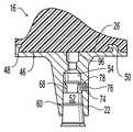
- FIG. 1is an exploded perspective view of a tibial knee component of the present invention
- FIG. 2is a cross-sectional view of an assembled tibial knee component of the present invention, showing also a modification to the embodiment shown in FIG. 1;
- FIG. 3is a cross-sectional view similar to that of FIG. 2, but showing the structure for the attachment of a bearing different from that shown in FIG. 1 and FIG. 2;
- FIG. 4is an enlarged perspective view of the tibial plug shown in the preceding Figs.;
- FIG. 5is an end view of the tibial plug shown in FIG. 4, the view taken in the direction 5 — 5 shown in FIG. 4;
- FIG. 6is an enlarged perspective view of the area designated by numeral 6 in FIG. 4;
- FIG. 7is a perspective view of yet another modified form of the tibial knee component of the present invention.
- FIG. 8is a perspective view, in partial cross-section, illustrating the manner of assembling the tibial plug and the tibial tray of the present invention.
- an exemplary orthopaedic devicein the form of a tibial knee component 10 designed to be implanted within a proximal tibia (not shown).
- Tibial knee component 10engages with a femoral knee component (not shown) which is implanted within a distal femur, as those knowledgeable in the art will understand readily.
- Tibial knee component 10is modular in design, and includes a tibial plug 12 , a tibial tray 14 and a bearing 16 , each of which may be provided in different sizes and varying configurations, and combined as needed.
- a proximal end 20 of tibial plug 12is adapted for engagement with and attachment to tibial tray 14 .
- Tibial tray 14has a distally extending socket 22 adapted for engagement with and attachment to proximal end 20 of tibial plug 12 , as will be described more fully hereinafter.
- Tibial tray 14further includes a proximal tibial plateau 24 having a generally planar proximal surface 26 which extends transverse (e.g., generally orthogonal) to a longitudinal axis of socket 22 .
- Tibial tray 14also includes a first retaining wall 30 and a second retaining wall 32 , each including an undercut 34 , 36 , respectively.
- Undercut 34 of first retaining wall 30extends the full length of first retaining wall 30
- undercut 36 of second retaining wall 32extends the full length of second retaining wall 32 .
- First and second retaining walls 30 and 32are disposed near outer edges of tibial plateau 24 , essentially on opposite sides of tibial plateau 24 , and together with design features of bearing 16 to be described hereinafter, secure bearing 16 to tibial tray 14 .
- Bearing 16has an articular bearing surface 42 for engagement with the femoral component.
- Articular bearing surface 42is disposed on either side of a center projection 44 .
- Each discrete portion of articular bearing surface 42 on either side of projection 44engages a corresponding condyle (not shown) of the femoral knee component, with center projection 44 being disposed between the condyles.
- Bearing 16has a backing surface 46 which engages with tibial plateau 24 .
- Backing surface 46is generally planar, and shaped to match the corresponding generally planar configuration of proximal surface 26 of tibial plateau 24 .
- Backing surface 46defines a load bearing surface with tibial plateau 24 , which transfers the load imparted either by tibial plateau 24 or the femoral condyles engaging articular bearing surface 42 .
- backing surface 46 of bearing 16is sized and configured such that backing surface 46 is substantially entirely supported by tibial plateau 24 , and includes a first channel 48 and a second channel 50 adapted and arranged to engage first retaining wall 30 and second retaining wall 32 , respectively.
- Bearing 16is assembled onto tibial tray 14 by engaging first channel 48 with first retaining wall 30 , and engaging second channel 50 with second retaining wall 32 . Engagement may be achieved by aligning channels 48 and 50 with retaining walls 30 and 32 , at ends thereof, and sliding bearing 16 on to tibial tray 14 .
- bearing 16is constructed from a plastic (e.g., UHMWPE) and tibial tray 14 is constructed from a metal (e.g., cobaltchromium alloy).
- proximal end 20 of tibial plug 12in a conical or frustoconical shape, having a tapered outer surface 52 ; and to provide socket 22 in an appropriate size and shape to receive proximal end 20 therein.
- An internal surface 54 in socket 22is of an appropriate shape and taper with respect to the shape and taper of outer surface 52 such as to provide an interference fit between internal surface 54 and outer surface 52 when proximal end is inserted deeply into socket 22 .
- socket 22is the female member
- proximal end 20is the male member of a so-called morse taper lock.
- Outer surface 52 and internal surface 54are engagement surfaces of the taper lock, for securing the tibial tray 14 to tibial plug 12 .
- a protuberance 60is provided on outer surface 52 of proximal end 20 , to provide interference and thereby securement between internal surface 54 and outer surface 52 .
- protuberance 60may take the form of a ridge 62 circumferentially disposed in outer surface 52 , formed during machining of surface 52 .
- a mallet 64FIG. 8
- localized deformationoccurs along ridge 62 , creating an intimate contact between the outer surface 52 and internal surface 54 in the area of the deformation.
- the deformationmay occur to protuberance 60 , outer surface 52 and/or internal surface 54 .
- protuberance 60also may take the form of an o-ring 66 disposed about outer surface 52 of tibial plug 12 proximal end 20 .
- O-ring 66may be made of suitable metal, plastic, rubber or elastomeric material.
- a groove, not shown,may be provided in outer surface 52 to receive and retain o-ring 66 .
- ridge 62as proximal end 20 is forced deeply into socket 22 , localized deformation occurs along o-ring 66 .
- outer surface 52 of proximal end 20further may include a circumferential recessed area 68 , which is recessed from outer surface 52 and defines a proximal abutment 72 .
- a threaded opening 74 (FIG. 2) in socket 22is aligned with recessed area 68 when tibial plug 12 is fully inserted in socket 22 .
- Threaded opening 74receives a correspondingly threaded set screw 76 , an inner tip 78 of which is seated in recessed area 68 , when set screw 76 is advanced sufficiently through threaded opening 74 .
- set screw 76When seated in recessed area 68 , set screw 76 further secures the axial position of tibial plug 12 within socket 22 , as relative axial movement between tibial plug 12 and socket 22 is constrained by the interference of set screw 76 inner tip 78 with proximal abutment 72 .
- set screw 76is one type of suitable locking member, which may also include other keys and the like forming an attachment between tibial plug 12 and socket 22 .
- inner tip 78also could be received in a threaded opening in distal end 18 of tibial plug 12 .
- a thicker bearing 80(FIG. 3 ), may be used. Enhanced fixation may be obtained where proximal end 20 of tibial plug 12 is provided with an internally threaded bore 82 , shown in FIG. 5 .
- Bearing 80includes a hole 84 extending therethrough, from the top thereof to backing surface 46 .
- the diameter of an upper portion 86 of hole 84 nearer articular bearing surface 42is greater than the diameter of a lower portion 88 of hole 84 nearer backing surface 46 .
- a threaded bolt 92having a head 94 , may be inserted partially through hole 84 .
- Bolt 92may be advanced through upper portion 86 , with head 94 being of a size to pass through upper portion 86 , but not through lower portion 88 .
- a hole 96 in tibial tray 14extends from proximal surface 26 to socket 22 , and is aligned with hole 84 of bearing 80 .
- Bolt 92extends through hole 96 so that threads of bolt 92 engage threaded bore 82 in plug 12 .
- Bolt 92is advanced within threaded bore 82 until head 94 of bolt 92 is seated against shoulder 90 , securing backing surface 46 of bearing 80 to tibial plateau 24 .
- head 94 of bolt 92is disposed in hole 84 well below articular bearing surface 42 of bearing 80 .
- tibial plug 12is affixed to tibial tray 14 by placing proximal end 20 of tibial plug 12 in socket 22 of tibial tray 14 .
- Proximal end 20is inserted deeply into socket 22 , and is set securely in place such as by applying an impact to distal end 18 by striking with mallet 64 or the like.
- Deformation of or around protuberance 60results. Deformation may occur in outer surface 52 , in internal surface 54 , and/or to protuberance 60 , depending on the physical characteristics of the material used for each.
- set screw 76is advanced inwardly, to set inner tip 78 thereof against proximal abutment 72 .
- Bearing 16 , 80is attached to tibial tray 14 , as described previously, and in the use of a bearing such as bearing 80 , head 94 of bolt 92 is tightened against shoulder 90 .
- the intimate engagement of protuberance 60 and internal surface 54 and the deformation which occurs to protuberance 60 or around and along protuberance 60 in outer surface 52 or internal surface 54create a barrier to the passage of materials along the region defined between outer surface 52 and internal surface 54 .
- the barrierfor example, inhibits passage of debris between the intramedullary canal and the articulating bearing surfaces. Contaminants are thereby inhibited from flowing in either direction through the morse taper lock.
- tibial tray 14has been shown and described having socket 22 defining a female member of the taper lock, and tibial plug 12 defining the male member of the taper lock
- a socketsuch as socket 22 can be provided on tibial plug 12 , and a corresponding male member of the taper lock defined by the distal end of tibial tray 14 .
Landscapes
- Health & Medical Sciences (AREA)
- Orthopedic Medicine & Surgery (AREA)
- Transplantation (AREA)
- Vascular Medicine (AREA)
- Oral & Maxillofacial Surgery (AREA)
- Engineering & Computer Science (AREA)
- Biomedical Technology (AREA)
- Heart & Thoracic Surgery (AREA)
- Cardiology (AREA)
- Life Sciences & Earth Sciences (AREA)
- Animal Behavior & Ethology (AREA)
- General Health & Medical Sciences (AREA)
- Public Health (AREA)
- Veterinary Medicine (AREA)
- Physical Education & Sports Medicine (AREA)
- Prostheses (AREA)
Abstract
Description
1. Field of the Invention
The present invention relates to orthopaedic implants, and, more particularly, to a modular orthopaedic implant having a taper lock joint, and to methods for assembling such modular orthopaedic components.
2. Description of the Related Art
Orthopaedic implants used to reconstruct a joint of a patient typically include two implant halves, with each implant half defining an articulating bearing surface. For example, an orthopaedic knee implant includes a femoral knee component which is placed within the distal femur and a tibial component which is placed within the proximal tibia. The femoral knee component typically includes a metallic articulating bearing surface which pivots on a non-metallic articulating bearing surface defined by the tibial knee component. The non-metallic bearing surface may be formed from a block of ultra-high molecular weight polyethylene (UHMWPE) which is machine to define the articulating bearing surface. The non-metallic bearing surface is attached to and carried by a tibial tray. The tray may in turn be affixed to a stem inserted within the intramedullary canal of the tibia. Pivotal movement between the femoral component and the bearing surface of the tibial component occurs with relatively low friction and wear characteristics.
To accommodate anatomical variations and differing surgical needs, it is known to provide a modular structure for the tibial component, which allows the assembly of different combinations of the bearing, tibial tray and tibial stem to meet the needs presented by the patient conditions. In one such modular structure, the tibial stem for the tibial knee component has a frustum shaped outer surface, and a complimentary tapered receiving member or socket on the tibial tray provides an interference fit in the nature of a morse taper lock between the tibial tray and the tibial stem, for affixing the tibial tray to the tibial stem. It is also known to provide a plug as an alternative to a stem where filling of the receiving member is desirable without an extending stem. Instances where such a plug is desirable include filling the receiving member to prevent debris transmission and providing a threaded plug for receiving an attachment screw to facilitate modular implant assembly.
The present invention provides an orthopaedic device having a first component and a second component having a novel structure providing affixation between components, and which further provides a barrier to contamination flow between the intramedullary canal and the articulating bearing surfaces.
The invention comprises, in one form thereof, an orthopaedic device having a first orthopaedic component including a first end defining an articulating bearing surface and a second end defining a first member of a morse taper lock; and a second orthopaedic component including a first end defining a second member of the morse taper lock. One of the first member and the second member includes a surface having a protuberance thereon.
The invention comprises, in another form thereof, an orthopaedic knee component for implanting within a proximal tibial. A tibial tray includes a proximal tibial plateau and a distally extending socket having an internal surface and defining a female member of a morse taper lock. A tibial plug has a proximal end having a tapered outer surface and defining a male member of the morse taper lock. A protuberance on the outer surface of the tibial plug creates localized deformation when the morse taper lock is assembled.
The invention comprises, in still another form thereof, a method for assembling a modular orthopaedic device. Steps of the method include providing a first component with a female member of a morse taper; providing a second component with a male member of the morse taper lock having a surface thereof with a protuberance thereon; engaging the male member of the morse taper lock with the female member of the morse taper lock; and impacting the second component, seating the second component in the first component and permanently deforming at least one of the protuberance, the female member and the male member.
An advantage of the present invention is that a known taper lock of a modular orthopaedic implant is provided with locking security between the components of the taper lock.
Another advantage of the present invention is that a barrier is formed to inhibit the passage of material between the distal end and the proximal end of a modular tibial implant.
The above-mentioned and other features and advantages of this invention, and the manner of attaining them, will become more apparent and the invention will be better understood by reference to the following description of several embodiments of the invention taken in conjunction with the accompanying drawings, wherein:
FIG. 1 is an exploded perspective view of a tibial knee component of the present invention;
FIG. 2 is a cross-sectional view of an assembled tibial knee component of the present invention, showing also a modification to the embodiment shown in FIG. 1;
FIG. 3 is a cross-sectional view similar to that of FIG. 2, but showing the structure for the attachment of a bearing different from that shown in FIG.1 and FIG. 2;
FIG. 4 is an enlarged perspective view of the tibial plug shown in the preceding Figs.;
FIG. 5 is an end view of the tibial plug shown in FIG. 4, the view taken in thedirection 5—5 shown in FIG. 4;
FIG. 6 is an enlarged perspective view of the area designated bynumeral 6 in FIG. 4;
FIG. 7 is a perspective view of yet another modified form of the tibial knee component of the present invention; and
FIG. 8 is a perspective view, in partial cross-section, illustrating the manner of assembling the tibial plug and the tibial tray of the present invention.
Corresponding reference characters indicate corresponding parts throughout the several views. The exemplifications set out herein illustrate a preferred embodiment of the invention, in several variations, and such exemplifications are not to be construed as limiting the scope of the invention in any manner.
Referring now to the drawings, and more particularly to FIG. 1, there is shown an exemplary orthopaedic device in the form of atibial knee component 10 designed to be implanted within a proximal tibia (not shown).Tibial knee component 10 engages with a femoral knee component (not shown) which is implanted within a distal femur, as those knowledgeable in the art will understand readily.
Bearing16 has abacking surface 46 which engages withtibial plateau 24.Backing surface 46 is generally planar, and shaped to match the corresponding generally planar configuration ofproximal surface 26 oftibial plateau 24.Backing surface 46 defines a load bearing surface withtibial plateau 24, which transfers the load imparted either bytibial plateau 24 or the femoral condyles engaging articular bearingsurface 42. As illustrated in FIG. 2,backing surface 46 ofbearing 16 is sized and configured such thatbacking surface 46 is substantially entirely supported bytibial plateau 24, and includes afirst channel 48 and asecond channel 50 adapted and arranged to engage first retainingwall 30 and secondretaining wall 32, respectively.Bearing 16 is assembled ontotibial tray 14 by engagingfirst channel 48 with firstretaining wall 30, and engagingsecond channel 50 with secondretaining wall 32. Engagement may be achieved by aligningchannels retaining walls tibial tray 14. In the embodiment shown,bearing 16 is constructed from a plastic (e.g., UHMWPE) andtibial tray 14 is constructed from a metal (e.g., cobaltchromium alloy).
It is known to provideproximal end 20 oftibial plug 12 in a conical or frustoconical shape, having a taperedouter surface 52; and to providesocket 22 in an appropriate size and shape to receiveproximal end 20 therein. Aninternal surface 54 insocket 22 is of an appropriate shape and taper with respect to the shape and taper ofouter surface 52 such as to provide an interference fit betweeninternal surface 54 andouter surface 52 when proximal end is inserted deeply intosocket 22. Thus,socket 22 is the female member, andproximal end 20 is the male member of a so-called morse taper lock.Outer surface 52 andinternal surface 54 are engagement surfaces of the taper lock, for securing thetibial tray 14 totibial plug 12.
In accordance with an aspect of the present invention, aprotuberance 60 is provided onouter surface 52 ofproximal end 20, to provide interference and thereby securement betweeninternal surface 54 andouter surface 52. As can been seen most clearly in the enlarged views of FIG.4 and FIG. 6,protuberance 60 may take the form of aridge 62 circumferentially disposed inouter surface 52, formed during machining ofsurface 52. Asproximal end 20 oftibial plug 12 is forced deeply intosocket 22, such as by impacting with a mallet64 (FIG.8), localized deformation occurs alongridge 62, creating an intimate contact between theouter surface 52 andinternal surface 54 in the area of the deformation. Depending on the hardness of materials used to form the components, the deformation may occur toprotuberance 60,outer surface 52 and/orinternal surface 54.
As shown in FIG. 7,protuberance 60 also may take the form of an o-ring 66 disposed aboutouter surface 52 of tibial plug12proximal end 20. O-ring 66 may be made of suitable metal, plastic, rubber or elastomeric material. A groove, not shown, may be provided inouter surface 52 to receive and retain o-ring 66. Similarly to the previous description forridge 62, asproximal end 20 is forced deeply intosocket 22, localized deformation occurs along o-ring 66.
In accordance with another aspect of the present invention,outer surface 52 ofproximal end 20 further may include a circumferential recessedarea 68, which is recessed fromouter surface 52 and defines aproximal abutment 72. A threaded opening74 (FIG. 2) insocket 22 is aligned with recessedarea 68 when tibial plug12 is fully inserted insocket 22. Threadedopening 74 receives a correspondingly threaded setscrew 76, aninner tip 78 of which is seated in recessedarea 68, when setscrew 76 is advanced sufficiently through threadedopening 74. When seated in recessedarea 68, setscrew 76 further secures the axial position oftibial plug 12 withinsocket 22, as relative axial movement betweentibial plug 12 andsocket 22 is constrained by the interference ofset screw 76inner tip 78 withproximal abutment 72. It should be understood that setscrew 76 is one type of suitable locking member, which may also include other keys and the like forming an attachment betweentibial plug 12 andsocket 22. For example,inner tip 78 also could be received in a threaded opening indistal end 18 oftibial plug 12.
Under some conditions, athicker bearing 80, (FIG.3), may be used. Enhanced fixation may be obtained whereproximal end 20 oftibial plug 12 is provided with an internally threaded bore82, shown in FIG.5.Bearing 80 includes ahole 84 extending therethrough, from the top thereof to backingsurface 46. The diameter of anupper portion 86 ofhole 84 nearer articular bearingsurface 42 is greater than the diameter of alower portion 88 ofhole 84nearer backing surface 46. At the transition betweenupper portion 86 andlower portion 88, ashoulder 90 is defined. A threadedbolt 92, having a head94, may be inserted partially throughhole 84.Bolt 92 may be advanced throughupper portion 86, with head94 being of a size to pass throughupper portion 86, but not throughlower portion 88. Ahole 96 intibial tray 14 extends fromproximal surface 26 tosocket 22, and is aligned withhole 84 ofbearing 80.Bolt 92 extends throughhole 96 so that threads ofbolt 92 engage threaded bore82 inplug 12.Bolt 92 is advanced within threaded bore82 until head94 ofbolt 92 is seated againstshoulder 90, securingbacking surface 46 of bearing80 totibial plateau 24. Properly secured, head94 ofbolt 92 is disposed inhole 84 well below articular bearingsurface 42 ofbearing 80.
In the use of atibial knee component 10 of the present invention, after having determined the appropriate size and type oftibial plug 12,tibial tray 14 andbearing tibial plug 12 is affixed totibial tray 14 by placingproximal end 20 of tibial plug12 insocket 22 oftibial tray 14.Proximal end 20 is inserted deeply intosocket 22, and is set securely in place such as by applying an impact todistal end 18 by striking withmallet 64 or the like. Deformation of or aroundprotuberance 60 results. Deformation may occur inouter surface 52, ininternal surface 54, and/or to protuberance60, depending on the physical characteristics of the material used for each. For embodiments provided with the feature, setscrew 76 is advanced inwardly, to setinner tip 78 thereof againstproximal abutment 72.Bearing tibial tray 14, as described previously, and in the use of a bearing such as bearing80, head94 ofbolt 92 is tightened againstshoulder 90.
In addition to the securement of tibial plug12 insocket 22 oftibial tray 14, the intimate engagement ofprotuberance 60 andinternal surface 54 and the deformation which occurs to protuberance60 or around and alongprotuberance 60 inouter surface 52 orinternal surface 54, create a barrier to the passage of materials along the region defined betweenouter surface 52 andinternal surface 54. The barrier, for example, inhibits passage of debris between the intramedullary canal and the articulating bearing surfaces. Contaminants are thereby inhibited from flowing in either direction through the morse taper lock.
It should be understood that the concepts of the present invention can be used with other types of orthopaedic devices having taper lock joint, e.g., hip implants, shoulder implants, and others with taper lock joints. Likewise, variations to the exemplary embodiment described herein may be made. Different sizes, shapes and configurations of tibial plugs, tibial trays and bearings may be combined, as necessary, for the conditions presented. Variations in construction may be used. For example, whiletibial tray 14 has been shown and described havingsocket 22 defining a female member of the taper lock, and tibial plug12 defining the male member of the taper lock, a socket such assocket 22 can be provided ontibial plug 12, and a corresponding male member of the taper lock defined by the distal end oftibial tray 14.
While this invention has been described as having a preferred design, the present invention can be further modified within the spirit and scope of this disclosure. This application is therefore intended to cover any variations, uses, or adaptations of the invention using its general principles. Further, this application is intended to cover such departures from the present disclosure as come within known or customary practice in the art to which this invention pertains and which fall within the limits of the appended claims.
Claims (2)
1. An orthopaedic knee component for implanting within a proximal tibia, comprising:
a tibial tray including-a proximal tibial plateau and a distally extending socket having an internal surface and defining a female member of a morse taper lock;
a bearing carried by said tibial tray on said proximal tibial plateau, and having an articular bearing surface for engagement with a femoral component; and
a tibial plug having a proximal end and a distal end, said proximal end of said tibial plug having a tapered outer surface and defining a male member of said morse taper lock, said tapered outer surface having a protuberance thereon, wherein said protuberance comprises a circumferential ridge in said outer surface of said tibial plug, and wherein each said ridge and said internal surface of said socket are intimately engaged and define localized deformation such that said ridge and said localized deformation define a means for inhibiting contaminant flow through said morse taper lock and said socket defines a threaded opening therethrough; and
a set screw disposed in threaded engagement with said threaded opening and extending from said socket to said tibial plug, wherein a recessed area in said outer surface defines a proximal abutment surface and said set screw includes an inner tip received by said proximal abutment surface.
2. An orthopaedic knee component for implanting within a proximal tibia, comprising:
a tibial tray including a proximal tibial plateau and a distally extending socket having an internal surface and defining a female member of a morse taper lock;
a bearing carried by said tibial tray on said proximal tibial plateau, and having an articular bearing surface for engagement with a femoral component; and
a tibial plug having a proximal end and a distal end, said proximal end of said tibial plug having a tapered outer surface and defining a male member of said morse taper lock, said tapered outer surface having a protuberance thereon, wherein said protuberance comprises a circumferential ridge in said outer surface of said tibial plug, and wherein each said ridge and said internal surface of said socket are intimately engaged and define localized deformation such that said ridge and said localized deformation define a means for inhibiting contaminant flow through said morse taper lock and said socket defines a threaded opening therethrough; and
a set screw disposed in threaded engagement with said threaded opening and extending from said socket to said tibial plug, wherein said proximal end of said tibial plug defines a thread bore, and a bolt extending through said bearing and said tibial tray is engaged with said threaded bore.
Priority Applications (1)
| Application Number | Priority Date | Filing Date | Title |
|---|---|---|---|
| US09/586,079US6436145B1 (en) | 2000-06-02 | 2000-06-02 | Plug for a modular orthopaedic implant and method for assembly |
Applications Claiming Priority (1)
| Application Number | Priority Date | Filing Date | Title |
|---|---|---|---|
| US09/586,079US6436145B1 (en) | 2000-06-02 | 2000-06-02 | Plug for a modular orthopaedic implant and method for assembly |
Publications (1)
| Publication Number | Publication Date |
|---|---|
| US6436145B1true US6436145B1 (en) | 2002-08-20 |
Family
ID=24344217
Family Applications (1)
| Application Number | Title | Priority Date | Filing Date |
|---|---|---|---|
| US09/586,079Expired - LifetimeUS6436145B1 (en) | 2000-06-02 | 2000-06-02 | Plug for a modular orthopaedic implant and method for assembly |
Country Status (1)
| Country | Link |
|---|---|
| US (1) | US6436145B1 (en) |
Cited By (68)
| Publication number | Priority date | Publication date | Assignee | Title |
|---|---|---|---|---|
| US20030014122A1 (en)* | 2001-04-02 | 2003-01-16 | Whiteside Biomechanics, Inc. | Tray and liner for joint replacement system |
| US20070162145A1 (en)* | 2002-04-25 | 2007-07-12 | Zimmer Technology, Inc. | Modular bone implant, tool, and method |
| US7306628B2 (en) | 2002-10-29 | 2007-12-11 | St. Francis Medical Technologies | Interspinous process apparatus and method with a selectably expandable spacer |
| US20080027557A1 (en)* | 2006-05-09 | 2008-01-31 | Finsbury (Development) Limited | Knee Prosthesis |
| US7326252B2 (en) | 2002-12-20 | 2008-02-05 | Smith & Nephew, Inc. | High performance knee prostheses |
| US7335203B2 (en) | 2003-02-12 | 2008-02-26 | Kyphon Inc. | System and method for immobilizing adjacent spinous processes |
| US7445639B2 (en) | 2001-02-23 | 2008-11-04 | Biomet Manufacturing Corp. | Knee joint prosthesis |
| US20080306603A1 (en)* | 2007-06-11 | 2008-12-11 | Aesculap Ag | Modular implant part and knee joint prosthesis |
| US7473268B2 (en) | 1998-10-20 | 2009-01-06 | Kyphon Sarl | Mating insertion instruments for spinal implants and methods of use |
| US7497874B1 (en) | 2001-02-23 | 2009-03-03 | Biomet Manufacturing Corp. | Knee joint prosthesis |
| US7510567B2 (en) | 1997-01-02 | 2009-03-31 | Kyphon Sarl | Spinal implants, insertion instruments, and methods of use |
| US7524324B2 (en) | 2004-04-28 | 2009-04-28 | Kyphon Sarl | System and method for an interspinous process implant as a supplement to a spine stabilization implant |
| US7549999B2 (en) | 2003-05-22 | 2009-06-23 | Kyphon Sarl | Interspinous process distraction implant and method of implantation |
| US7591851B2 (en) | 2004-12-13 | 2009-09-22 | Kyphon Sarl | Inter-cervical facet implant and method |
| US20090281632A1 (en)* | 2008-05-09 | 2009-11-12 | Remi Sciences, Inc. | Ulnar head prosthesis system |
| US7621939B2 (en) | 1997-01-02 | 2009-11-24 | Kyphon Sarl | Supplemental spine fixation device and method |
| US7749252B2 (en) | 2005-03-21 | 2010-07-06 | Kyphon Sarl | Interspinous process implant having deployable wing and method of implantation |
| US7758619B2 (en) | 1997-01-02 | 2010-07-20 | Kyphon SÀRL | Spinous process implant with tethers |
| US7763050B2 (en) | 2004-12-13 | 2010-07-27 | Warsaw Orthopedic, Inc. | Inter-cervical facet implant with locking screw and method |
| US20100234962A1 (en)* | 2001-01-29 | 2010-09-16 | Zimmer Technology, Inc. | Constrained prosthetic knee with rotating bearing |
| US7799084B2 (en) | 2002-10-23 | 2010-09-21 | Mako Surgical Corp. | Modular femoral component for a total knee joint replacement for minimally invasive implantation |
| US7833246B2 (en) | 2002-10-29 | 2010-11-16 | Kyphon SÀRL | Interspinous process and sacrum implant and method |
| US7909853B2 (en) | 2004-09-23 | 2011-03-22 | Kyphon Sarl | Interspinous process implant including a binder and method of implantation |
| US20110071642A1 (en)* | 2008-03-07 | 2011-03-24 | Aesculap Ag | Medical implant and knee joint endoprosthesis |
| US7935151B2 (en) | 2001-03-05 | 2011-05-03 | Hudson Surgical Design, Inc. | Femoral prosthetic implant |
| US7959652B2 (en) | 2005-04-18 | 2011-06-14 | Kyphon Sarl | Interspinous process implant having deployable wings and method of implantation |
| US7967822B2 (en) | 1994-09-02 | 2011-06-28 | Hudson Surgical Design, Inc. | Methods and apparatus for orthopedic implants |
| US8012209B2 (en) | 2004-09-23 | 2011-09-06 | Kyphon Sarl | Interspinous process implant including a binder, binder aligner and method of implantation |
| US8021368B2 (en) | 2004-01-14 | 2011-09-20 | Hudson Surgical Design, Inc. | Methods and apparatus for improved cutting tools for resection |
| US8048117B2 (en) | 2003-05-22 | 2011-11-01 | Kyphon Sarl | Interspinous process implant and method of implantation |
| US8070778B2 (en) | 2003-05-22 | 2011-12-06 | Kyphon Sarl | Interspinous process implant with slide-in distraction piece and method of implantation |
| US8114083B2 (en) | 2004-01-14 | 2012-02-14 | Hudson Surgical Design, Inc. | Methods and apparatus for improved drilling and milling tools for resection |
| US20120059484A1 (en)* | 2002-04-25 | 2012-03-08 | Zimmer Technology, Inc. | Modular bone implant, tools, and method |
| US8157869B2 (en) | 2007-01-10 | 2012-04-17 | Biomet Manufacturing Corp. | Knee joint prosthesis system and method for implantation |
| US8163028B2 (en) | 2007-01-10 | 2012-04-24 | Biomet Manufacturing Corp. | Knee joint prosthesis system and method for implantation |
| US8187280B2 (en) | 2007-10-10 | 2012-05-29 | Biomet Manufacturing Corp. | Knee joint prosthesis system and method for implantation |
| US8287545B2 (en) | 2004-01-14 | 2012-10-16 | Hudson Surgical Design, Inc. | Methods and apparatus for enhanced retention of prosthetic implants |
| US8328873B2 (en) | 2007-01-10 | 2012-12-11 | Biomet Manufacturing Corp. | Knee joint prosthesis system and method for implantation |
| US20120323333A1 (en)* | 2011-06-17 | 2012-12-20 | Biomet Manufacturing, Corp. | Revision knee tibial locking mechanism |
| US8425530B2 (en) | 2004-12-13 | 2013-04-23 | Warsaw Orthopedic, Inc. | Apparatus for sizing a facet joint |
| USRE44476E1 (en) | 2001-01-29 | 2013-09-03 | Zimmer, Inc. | Constrained prosthetic knee with rotating bearing |
| US8562616B2 (en) | 2007-10-10 | 2013-10-22 | Biomet Manufacturing, Llc | Knee joint prosthesis system and method for implantation |
| US8603095B2 (en) | 1994-09-02 | 2013-12-10 | Puget Bio Ventures LLC | Apparatuses for femoral and tibial resection |
| US8740906B2 (en) | 2004-01-14 | 2014-06-03 | Hudson Surgical Design, Inc. | Method and apparatus for wireplasty bone resection |
| US8911501B2 (en) | 2011-12-29 | 2014-12-16 | Mako Surgical Corp. | Cruciate-retaining tibial prosthesis |
| US8926709B2 (en) | 2010-08-12 | 2015-01-06 | Smith & Nephew, Inc. | Structures for use in orthopaedic implant fixation and methods of installation onto a bone |
| US20150012106A1 (en)* | 2010-06-01 | 2015-01-08 | Smith & Nephew, Inc. | Orthopaedic implant system and fasteners for use therein |
| US8961612B2 (en) | 2012-08-30 | 2015-02-24 | Biomet Manufacturing, Llc | Knee component having orbital interface boss |
| US9198762B2 (en) | 2011-01-10 | 2015-12-01 | Howmedica Osteonics Corp. | Bicruciate retaining tibial baseplate |
| US9345578B2 (en) | 2013-02-22 | 2016-05-24 | Stryker Corporation | Bicruciate retaining tibial implant system |
| US20160287397A1 (en)* | 2010-07-24 | 2016-10-06 | Zimmer, Inc. | Asymmetric tibial components for a knee prosthesis |
| DE102015209520B3 (en)* | 2015-05-22 | 2016-10-27 | Peter Brehm Holding Gmbh & Co. Kg | Modular stem endoprostheses |
| US9642711B2 (en) | 2003-10-17 | 2017-05-09 | Smith & Nephew, Inc. | High flexion articular insert |
| US9730799B2 (en) | 2006-06-30 | 2017-08-15 | Smith & Nephew, Inc. | Anatomical motion hinged prosthesis |
| US9763795B2 (en) | 2010-09-10 | 2017-09-19 | Zimmer, Inc. | Motion facilitating tibial components for a knee prosthesis |
| US9763794B2 (en) | 2010-07-24 | 2017-09-19 | Zimmer, Inc. | Tibial prosthesis |
| US9861490B2 (en) | 2010-07-24 | 2018-01-09 | Zimmer, Inc. | Asymmetric tibial components for a knee prosthesis |
| US10188530B2 (en) | 2010-12-17 | 2019-01-29 | Zimmer, Inc. | Provisional tibial prosthesis system |
| US10231840B2 (en) | 2016-07-27 | 2019-03-19 | Howmedica Osteonics Corp. | Low profile tibial baseplate with fixation members |
| US10265181B2 (en) | 2011-11-21 | 2019-04-23 | Zimmer, Inc. | Tibial baseplate with asymmetric placement of fixation structures |
| US10278827B2 (en) | 2015-09-21 | 2019-05-07 | Zimmer, Inc. | Prosthesis system including tibial bearing component |
| US10675153B2 (en) | 2017-03-10 | 2020-06-09 | Zimmer, Inc. | Tibial prosthesis with tibial bearing component securing feature |
| US10835380B2 (en) | 2018-04-30 | 2020-11-17 | Zimmer, Inc. | Posterior stabilized prosthesis system |
| US10898337B2 (en) | 2011-11-18 | 2021-01-26 | Zimmer, Inc. | Tibial bearing component for a knee prosthesis with improved articular characteristics |
| US11324599B2 (en) | 2017-05-12 | 2022-05-10 | Zimmer, Inc. | Femoral prostheses with upsizing and downsizing capabilities |
| US11324598B2 (en) | 2013-08-30 | 2022-05-10 | Zimmer, Inc. | Method for optimizing implant designs |
| US11426282B2 (en) | 2017-11-16 | 2022-08-30 | Zimmer, Inc. | Implants for adding joint inclination to a knee arthroplasty |
| US20230000633A1 (en)* | 2019-12-16 | 2023-01-05 | Waldemar Link Gmbh & Co. Kg | Implant component |
Citations (5)
| Publication number | Priority date | Publication date | Assignee | Title |
|---|---|---|---|---|
| US4936853A (en)* | 1989-01-11 | 1990-06-26 | Kirschner Medical Corporation | Modular knee prosthesis |
| US5405403A (en)* | 1994-03-18 | 1995-04-11 | Mikhail; W. E. Michael | Femoral prosthesis with anti-rotation feature for ball |
| US5766260A (en)* | 1995-06-06 | 1998-06-16 | Whiteside; Leo A. | Acetabular component with improved liner seal and lock |
| US6099569A (en)* | 1996-07-24 | 2000-08-08 | Waldemar Link (Gmbh & Co.) | Endoprosthesis |
| US6132469A (en)* | 1997-11-07 | 2000-10-17 | Biomet, Inc. | Acetabular liner extractor |
- 2000
- 2000-06-02USUS09/586,079patent/US6436145B1/ennot_activeExpired - Lifetime
Patent Citations (5)
| Publication number | Priority date | Publication date | Assignee | Title |
|---|---|---|---|---|
| US4936853A (en)* | 1989-01-11 | 1990-06-26 | Kirschner Medical Corporation | Modular knee prosthesis |
| US5405403A (en)* | 1994-03-18 | 1995-04-11 | Mikhail; W. E. Michael | Femoral prosthesis with anti-rotation feature for ball |
| US5766260A (en)* | 1995-06-06 | 1998-06-16 | Whiteside; Leo A. | Acetabular component with improved liner seal and lock |
| US6099569A (en)* | 1996-07-24 | 2000-08-08 | Waldemar Link (Gmbh & Co.) | Endoprosthesis |
| US6132469A (en)* | 1997-11-07 | 2000-10-17 | Biomet, Inc. | Acetabular liner extractor |
Cited By (137)
| Publication number | Priority date | Publication date | Assignee | Title |
|---|---|---|---|---|
| US7967822B2 (en) | 1994-09-02 | 2011-06-28 | Hudson Surgical Design, Inc. | Methods and apparatus for orthopedic implants |
| US9066804B2 (en) | 1994-09-02 | 2015-06-30 | Puget Bioventures Llc | Method and apparatus for femoral and tibial resection |
| US8603095B2 (en) | 1994-09-02 | 2013-12-10 | Puget Bio Ventures LLC | Apparatuses for femoral and tibial resection |
| US7510567B2 (en) | 1997-01-02 | 2009-03-31 | Kyphon Sarl | Spinal implants, insertion instruments, and methods of use |
| US7918877B2 (en) | 1997-01-02 | 2011-04-05 | Kyphon Sarl | Lateral insertion method for spinous process spacer with deployable member |
| US7955356B2 (en) | 1997-01-02 | 2011-06-07 | Kyphon Sarl | Laterally insertable interspinous process implant |
| US7901432B2 (en) | 1997-01-02 | 2011-03-08 | Kyphon Sarl | Method for lateral implantation of spinous process spacer |
| US7828822B2 (en) | 1997-01-02 | 2010-11-09 | Kyphon SÀRL | Spinous process implant |
| US7758619B2 (en) | 1997-01-02 | 2010-07-20 | Kyphon SÀRL | Spinous process implant with tethers |
| US7621939B2 (en) | 1997-01-02 | 2009-11-24 | Kyphon Sarl | Supplemental spine fixation device and method |
| US7473268B2 (en) | 1998-10-20 | 2009-01-06 | Kyphon Sarl | Mating insertion instruments for spinal implants and methods of use |
| US8268006B2 (en)* | 2001-01-29 | 2012-09-18 | Zimmer, Inc. | Constrained prosthetic knee with rotating bearing |
| USRE44476E1 (en) | 2001-01-29 | 2013-09-03 | Zimmer, Inc. | Constrained prosthetic knee with rotating bearing |
| US20100234962A1 (en)* | 2001-01-29 | 2010-09-16 | Zimmer Technology, Inc. | Constrained prosthetic knee with rotating bearing |
| US8888857B2 (en) | 2001-01-29 | 2014-11-18 | Zimmer, Inc. | Constrained prosthetic knee with rotating bearing |
| US7497874B1 (en) | 2001-02-23 | 2009-03-03 | Biomet Manufacturing Corp. | Knee joint prosthesis |
| US7445639B2 (en) | 2001-02-23 | 2008-11-04 | Biomet Manufacturing Corp. | Knee joint prosthesis |
| US7935151B2 (en) | 2001-03-05 | 2011-05-03 | Hudson Surgical Design, Inc. | Femoral prosthetic implant |
| US9192391B2 (en) | 2001-03-05 | 2015-11-24 | Puget Bioventures Llc | Method for minimally invasive total knee arthroplasty |
| US8088167B2 (en) | 2001-03-05 | 2012-01-03 | Hudson Surgical Design, Inc. | Femoral prosthetic implant |
| US8062377B2 (en) | 2001-03-05 | 2011-11-22 | Hudson Surgical Design, Inc. | Methods and apparatus for knee arthroplasty |
| US8430932B2 (en) | 2001-03-05 | 2013-04-30 | Puget Bio Ventures LLC | Femoral prosthetic implant |
| US9421022B2 (en) | 2001-03-05 | 2016-08-23 | Puget Bioventures Llc | Method and apparatus for total knee arthroplasty |
| US20030014122A1 (en)* | 2001-04-02 | 2003-01-16 | Whiteside Biomechanics, Inc. | Tray and liner for joint replacement system |
| US8241367B2 (en) | 2002-04-25 | 2012-08-14 | Zimmer, Inc. | Modular bone implant, tool, and method |
| US20120059484A1 (en)* | 2002-04-25 | 2012-03-08 | Zimmer Technology, Inc. | Modular bone implant, tools, and method |
| US20070162145A1 (en)* | 2002-04-25 | 2007-07-12 | Zimmer Technology, Inc. | Modular bone implant, tool, and method |
| US7857858B2 (en) | 2002-04-25 | 2010-12-28 | Zimmer Technology, Inc. | Modular bone implant, tool, and method |
| US7799084B2 (en) | 2002-10-23 | 2010-09-21 | Mako Surgical Corp. | Modular femoral component for a total knee joint replacement for minimally invasive implantation |
| US7476251B2 (en) | 2002-10-29 | 2009-01-13 | Kyphon Sarl | Interspinous process apparatus and method with a selectably expandable spacer |
| US7833246B2 (en) | 2002-10-29 | 2010-11-16 | Kyphon SÀRL | Interspinous process and sacrum implant and method |
| US7306628B2 (en) | 2002-10-29 | 2007-12-11 | St. Francis Medical Technologies | Interspinous process apparatus and method with a selectably expandable spacer |
| US7803190B2 (en) | 2002-10-29 | 2010-09-28 | Kyphon SÀRL | Interspinous process apparatus and method with a selectably expandable spacer |
| US8449618B2 (en) | 2002-12-20 | 2013-05-28 | Smith & Nephew, Inc. | High performance knee prostheses |
| US8652210B2 (en) | 2002-12-20 | 2014-02-18 | Smith & Nephew, Inc. | Femoral prostheses with lateral buttress for patella |
| US7922771B2 (en) | 2002-12-20 | 2011-04-12 | Smith & Nephew, Inc. | High performance knee prostheses |
| US9320605B2 (en) | 2002-12-20 | 2016-04-26 | Smith & Nephew, Inc. | High performance knee prostheses |
| US7326252B2 (en) | 2002-12-20 | 2008-02-05 | Smith & Nephew, Inc. | High performance knee prostheses |
| US9707087B2 (en) | 2002-12-20 | 2017-07-18 | Smith & Nephew, Inc. | High performance knee prosthesis |
| US9402729B2 (en) | 2002-12-20 | 2016-08-02 | Smith & Nephew, Inc. | High performance knee prostheses |
| US8647389B2 (en) | 2002-12-20 | 2014-02-11 | Smith & Nephew, Inc. | High performance knee prostheses |
| US10149768B2 (en) | 2002-12-20 | 2018-12-11 | Smith & Nephew, Inc. | High performance knee prostheses |
| US11369477B2 (en) | 2002-12-20 | 2022-06-28 | Smith & Nephew, Inc. | High performance knee prostheses |
| US8603178B2 (en) | 2002-12-20 | 2013-12-10 | Smith & Nephew, Inc. | Knee prostheses with convex portion on tibial lateral articular surface |
| US8425617B2 (en) | 2002-12-20 | 2013-04-23 | Smith & Nephew, Inc. | Knee prostheses with convex slope on portion of tibial articular surface |
| US8403992B2 (en) | 2002-12-20 | 2013-03-26 | Smith & Nephew, Inc. | High performance knee prostheses |
| US8398716B2 (en) | 2002-12-20 | 2013-03-19 | Smith & Nephew, Inc. | High performance knee prostheses with posterior cam |
| US8398715B2 (en) | 2002-12-20 | 2013-03-19 | Smith & Nephew, Inc. | High performance knee prostheses with converging anterior and posterior portions |
| US8394148B2 (en) | 2002-12-20 | 2013-03-12 | Smith & Nephew, Inc. | Tibial component of high performance knee prosthesis |
| US8394147B2 (en) | 2002-12-20 | 2013-03-12 | Smith & Nephew, Inc. | High performance femoral knee prostheses |
| US7335203B2 (en) | 2003-02-12 | 2008-02-26 | Kyphon Inc. | System and method for immobilizing adjacent spinous processes |
| US8070778B2 (en) | 2003-05-22 | 2011-12-06 | Kyphon Sarl | Interspinous process implant with slide-in distraction piece and method of implantation |
| US7695513B2 (en) | 2003-05-22 | 2010-04-13 | Kyphon Sarl | Distractible interspinous process implant and method of implantation |
| US8048117B2 (en) | 2003-05-22 | 2011-11-01 | Kyphon Sarl | Interspinous process implant and method of implantation |
| US7549999B2 (en) | 2003-05-22 | 2009-06-23 | Kyphon Sarl | Interspinous process distraction implant and method of implantation |
| US9642711B2 (en) | 2003-10-17 | 2017-05-09 | Smith & Nephew, Inc. | High flexion articular insert |
| US9814539B2 (en) | 2004-01-14 | 2017-11-14 | Puget Bioventures Llc | Methods and apparatus for conformable prosthetic implants |
| US8287545B2 (en) | 2004-01-14 | 2012-10-16 | Hudson Surgical Design, Inc. | Methods and apparatus for enhanced retention of prosthetic implants |
| US8298238B2 (en) | 2004-01-14 | 2012-10-30 | Hudson Surgical Design, Inc. | Methods and apparatus for pivotable guide surfaces for arthroplasty |
| US8740906B2 (en) | 2004-01-14 | 2014-06-03 | Hudson Surgical Design, Inc. | Method and apparatus for wireplasty bone resection |
| US8021368B2 (en) | 2004-01-14 | 2011-09-20 | Hudson Surgical Design, Inc. | Methods and apparatus for improved cutting tools for resection |
| US8114083B2 (en) | 2004-01-14 | 2012-02-14 | Hudson Surgical Design, Inc. | Methods and apparatus for improved drilling and milling tools for resection |
| US8353914B2 (en) | 2004-02-02 | 2013-01-15 | Hudson Surgical Design, Inc. | Methods and apparatus for improved profile based resection |
| US7524324B2 (en) | 2004-04-28 | 2009-04-28 | Kyphon Sarl | System and method for an interspinous process implant as a supplement to a spine stabilization implant |
| US7909853B2 (en) | 2004-09-23 | 2011-03-22 | Kyphon Sarl | Interspinous process implant including a binder and method of implantation |
| US8012209B2 (en) | 2004-09-23 | 2011-09-06 | Kyphon Sarl | Interspinous process implant including a binder, binder aligner and method of implantation |
| US8425530B2 (en) | 2004-12-13 | 2013-04-23 | Warsaw Orthopedic, Inc. | Apparatus for sizing a facet joint |
| US8100944B2 (en) | 2004-12-13 | 2012-01-24 | Kyphon Sarl | Inter-cervical facet implant and method for preserving the tissues surrounding the facet joint |
| US7601170B2 (en) | 2004-12-13 | 2009-10-13 | Kyphon Sarl | Inter-cervical facet implant and method |
| US7591851B2 (en) | 2004-12-13 | 2009-09-22 | Kyphon Sarl | Inter-cervical facet implant and method |
| US7763050B2 (en) | 2004-12-13 | 2010-07-27 | Warsaw Orthopedic, Inc. | Inter-cervical facet implant with locking screw and method |
| US7776090B2 (en) | 2004-12-13 | 2010-08-17 | Warsaw Orthopedic, Inc. | Inter-cervical facet implant and method |
| US7931674B2 (en) | 2005-03-21 | 2011-04-26 | Kyphon Sarl | Interspinous process implant having deployable wing and method of implantation |
| US7749252B2 (en) | 2005-03-21 | 2010-07-06 | Kyphon Sarl | Interspinous process implant having deployable wing and method of implantation |
| US7959652B2 (en) | 2005-04-18 | 2011-06-14 | Kyphon Sarl | Interspinous process implant having deployable wings and method of implantation |
| US20080027557A1 (en)* | 2006-05-09 | 2008-01-31 | Finsbury (Development) Limited | Knee Prosthesis |
| US12383405B2 (en) | 2006-06-30 | 2025-08-12 | Smith & Nephew, Inc. | Anatomical motion hinged prosthesis |
| US10779949B2 (en) | 2006-06-30 | 2020-09-22 | Smith & Nephew, Inc. | Anatomical motion hinged prosthesis |
| US9730799B2 (en) | 2006-06-30 | 2017-08-15 | Smith & Nephew, Inc. | Anatomical motion hinged prosthesis |
| US8157869B2 (en) | 2007-01-10 | 2012-04-17 | Biomet Manufacturing Corp. | Knee joint prosthesis system and method for implantation |
| US8328873B2 (en) | 2007-01-10 | 2012-12-11 | Biomet Manufacturing Corp. | Knee joint prosthesis system and method for implantation |
| US8163028B2 (en) | 2007-01-10 | 2012-04-24 | Biomet Manufacturing Corp. | Knee joint prosthesis system and method for implantation |
| US8936648B2 (en) | 2007-01-10 | 2015-01-20 | Biomet Manufacturing, Llc | Knee joint prosthesis system and method for implantation |
| US8480751B2 (en) | 2007-01-10 | 2013-07-09 | Biomet Manufacturing, Llc | Knee joint prosthesis system and method for implantation |
| US8540775B2 (en) | 2007-06-11 | 2013-09-24 | Aesculap Ag | Modular implant part and knee joint prosthesis |
| US20080306603A1 (en)* | 2007-06-11 | 2008-12-11 | Aesculap Ag | Modular implant part and knee joint prosthesis |
| US9763793B2 (en) | 2007-10-10 | 2017-09-19 | Biomet Manufacturing, Llc | Knee joint prosthesis system and method for implantation |
| US8562616B2 (en) | 2007-10-10 | 2013-10-22 | Biomet Manufacturing, Llc | Knee joint prosthesis system and method for implantation |
| US10736747B2 (en) | 2007-10-10 | 2020-08-11 | Biomet Manufacturing, Llc | Knee joint prosthesis system and method for implantation |
| US8187280B2 (en) | 2007-10-10 | 2012-05-29 | Biomet Manufacturing Corp. | Knee joint prosthesis system and method for implantation |
| US9044328B2 (en) | 2008-03-07 | 2015-06-02 | Aesculap Ag | Medical implant and knee joint endoprosthesis |
| US20110071642A1 (en)* | 2008-03-07 | 2011-03-24 | Aesculap Ag | Medical implant and knee joint endoprosthesis |
| US9649204B2 (en) | 2008-03-07 | 2017-05-16 | Aesculap Ag | Medical implant and knee joint endoprosthesis |
| US8052755B2 (en)* | 2008-05-09 | 2011-11-08 | Remi Sciences, Inc. | Ulnar head prosthesis system |
| US20090281632A1 (en)* | 2008-05-09 | 2009-11-12 | Remi Sciences, Inc. | Ulnar head prosthesis system |
| US20150012106A1 (en)* | 2010-06-01 | 2015-01-08 | Smith & Nephew, Inc. | Orthopaedic implant system and fasteners for use therein |
| US9668872B2 (en)* | 2010-06-01 | 2017-06-06 | Smith & Nephew, Inc. | Orthopaedic implant system and fasteners for use therein |
| US12239540B2 (en) | 2010-07-24 | 2025-03-04 | Zimmer, Inc. | Asymmetric tibial components for a knee prosthesis |
| US11224519B2 (en) | 2010-07-24 | 2022-01-18 | Zimmer, Inc. | Asymmetric tibial components for a knee prosthesis |
| US10195041B2 (en) | 2010-07-24 | 2019-02-05 | Zimmer, Inc. | Asymmetric tibial components for a knee prosthesis |
| US9763796B2 (en)* | 2010-07-24 | 2017-09-19 | Zimmer, Inc. | Asymmetric tibial components for a knee prosthesis |
| US20160287397A1 (en)* | 2010-07-24 | 2016-10-06 | Zimmer, Inc. | Asymmetric tibial components for a knee prosthesis |
| US9763794B2 (en) | 2010-07-24 | 2017-09-19 | Zimmer, Inc. | Tibial prosthesis |
| US10543099B2 (en) | 2010-07-24 | 2020-01-28 | Zimmer, Inc. | Tibial prosthesis |
| US9861490B2 (en) | 2010-07-24 | 2018-01-09 | Zimmer, Inc. | Asymmetric tibial components for a knee prosthesis |
| US9918844B2 (en) | 2010-07-24 | 2018-03-20 | Zimmer, Inc. | Tibial prosthesis with a fixed bearing component |
| US10470889B2 (en) | 2010-07-24 | 2019-11-12 | Zimmer, Inc. | Asymmetric tibial components for a knee prosthesis |
| US8926709B2 (en) | 2010-08-12 | 2015-01-06 | Smith & Nephew, Inc. | Structures for use in orthopaedic implant fixation and methods of installation onto a bone |
| US9763795B2 (en) | 2010-09-10 | 2017-09-19 | Zimmer, Inc. | Motion facilitating tibial components for a knee prosthesis |
| US10413415B2 (en) | 2010-09-10 | 2019-09-17 | Zimmer, Inc. | Motion facilitating tibial components for a knee prosthesis |
| US11471288B2 (en) | 2010-09-10 | 2022-10-18 | Zimmer, Inc. | Motion facilitating tibial components for a knee prosthesis |
| US10188530B2 (en) | 2010-12-17 | 2019-01-29 | Zimmer, Inc. | Provisional tibial prosthesis system |
| US9198762B2 (en) | 2011-01-10 | 2015-12-01 | Howmedica Osteonics Corp. | Bicruciate retaining tibial baseplate |
| US9408704B2 (en) | 2011-06-17 | 2016-08-09 | Biomet Manufacturing, Llc | Revision knee tibial locking mechanism |
| US8617250B2 (en)* | 2011-06-17 | 2013-12-31 | Biomet Manufacturing, Llc | Revision knee tibial locking mechanism |
| US20120323333A1 (en)* | 2011-06-17 | 2012-12-20 | Biomet Manufacturing, Corp. | Revision knee tibial locking mechanism |
| US12383407B2 (en) | 2011-11-18 | 2025-08-12 | Zimmer, Inc. | Tibial bearing component for a knee prosthesis with improved articular characteristics |
| US10898337B2 (en) | 2011-11-18 | 2021-01-26 | Zimmer, Inc. | Tibial bearing component for a knee prosthesis with improved articular characteristics |
| US10265181B2 (en) | 2011-11-21 | 2019-04-23 | Zimmer, Inc. | Tibial baseplate with asymmetric placement of fixation structures |
| US8911501B2 (en) | 2011-12-29 | 2014-12-16 | Mako Surgical Corp. | Cruciate-retaining tibial prosthesis |
| US10278825B2 (en) | 2012-08-30 | 2019-05-07 | Biomet Manufacturing, Llc | Knee component having orbital interface boss |
| US8961612B2 (en) | 2012-08-30 | 2015-02-24 | Biomet Manufacturing, Llc | Knee component having orbital interface boss |
| US9345578B2 (en) | 2013-02-22 | 2016-05-24 | Stryker Corporation | Bicruciate retaining tibial implant system |
| US11324598B2 (en) | 2013-08-30 | 2022-05-10 | Zimmer, Inc. | Method for optimizing implant designs |
| DE102015209520B3 (en)* | 2015-05-22 | 2016-10-27 | Peter Brehm Holding Gmbh & Co. Kg | Modular stem endoprostheses |
| US11160659B2 (en) | 2015-09-21 | 2021-11-02 | Zimmer, Inc. | Prosthesis system including tibial bearing component |
| US10278827B2 (en) | 2015-09-21 | 2019-05-07 | Zimmer, Inc. | Prosthesis system including tibial bearing component |
| USD884179S1 (en) | 2016-07-27 | 2020-05-12 | Howmedica Osteonics Corp. | Tibial baseplate with fixation members |
| US10231840B2 (en) | 2016-07-27 | 2019-03-19 | Howmedica Osteonics Corp. | Low profile tibial baseplate with fixation members |
| US10675153B2 (en) | 2017-03-10 | 2020-06-09 | Zimmer, Inc. | Tibial prosthesis with tibial bearing component securing feature |
| US11547571B2 (en) | 2017-03-10 | 2023-01-10 | Zimmer, Inc. | Tibial prosthesis with tibial bearing component securing feature |
| US11324599B2 (en) | 2017-05-12 | 2022-05-10 | Zimmer, Inc. | Femoral prostheses with upsizing and downsizing capabilities |
| US11426282B2 (en) | 2017-11-16 | 2022-08-30 | Zimmer, Inc. | Implants for adding joint inclination to a knee arthroplasty |
| US10835380B2 (en) | 2018-04-30 | 2020-11-17 | Zimmer, Inc. | Posterior stabilized prosthesis system |
| US11911279B2 (en) | 2018-04-30 | 2024-02-27 | Zimmer, Inc. | Posterior stabilized prosthesis system |
| US20230000633A1 (en)* | 2019-12-16 | 2023-01-05 | Waldemar Link Gmbh & Co. Kg | Implant component |
| EP3838224B1 (en)* | 2019-12-16 | 2023-08-09 | Waldemar Link GmbH & Co. KG | Humeral implant component |
Similar Documents
| Publication | Publication Date | Title |
|---|---|---|
| US6436145B1 (en) | Plug for a modular orthopaedic implant and method for assembly | |
| EP0850608B1 (en) | Modular joint prosthesis augmentation system | |
| US7842093B2 (en) | Method and apparatus for a knee implant | |
| EP0850606B1 (en) | Modular joint prosthesis stabilization and augmentation system | |
| EP1062922B1 (en) | Prothesis system | |
| US5534027A (en) | Method for providing a barrier to the advancement of wear debris in an orthopaedic implant assembly | |
| JP4083254B2 (en) | Artificial joint augmentation device | |
| US6773461B2 (en) | Constrained prosthetic knee with rotating bearing | |
| AU750643B2 (en) | Stem offset mechanism for joint prosthesis | |
| CA1277453C (en) | Fixation device for a ligament or tendon prosthesis | |
| US6699289B2 (en) | Augmented glenoid component having an interrupted surface and associated method for securing the augmented glenoid component to a glenoid surface of a scapula | |
| CA2367652C (en) | Constrained prosthetic knee with rotating bearing | |
| US8696754B2 (en) | Revision patella prosthesis | |
| US20170014236A1 (en) | Elbow prosthesis | |
| EP0853929A2 (en) | Orthopedic prosthesis employing bone screws and cement | |
| CA2597617A1 (en) | Apparatus and method for shoulder arthroplasty | |
| EP2664301A1 (en) | Prosthesis kit with finned sleeve | |
| EP0806921A4 (en) | Tibial prosthesis | |
| US5405392A (en) | Articular prosthetic device | |
| EP2777625B1 (en) | Prosthetic component | |
| US9044327B2 (en) | Structure improvement of an orthopaedic implant of an artificial knee joint | |
| KR20220129558A (en) | Implant Component Assemblies | |
| US20240024118A1 (en) | A Mechanically Secured Plastic Patellar Prosthesis | |
| US20240138990A1 (en) | Ceramic joint implant provided with locking device for screwing it | |
| JPH0515294Y2 (en) |
Legal Events
| Date | Code | Title | Description |
|---|---|---|---|
| AS | Assignment | Owner name:BRISTOL-MYERS SQUIBB COMPANY, NEW YORK Free format text:ASSIGNMENT OF ASSIGNORS INTEREST;ASSIGNORS:MILLER, CLAYTON;TANAMAL, LINGGAWATI;WEBSTER, VINCENT;AND OTHERS;REEL/FRAME:010843/0913;SIGNING DATES FROM 20000503 TO 20000530 | |
| AS | Assignment | Owner name:ZIMMER, INC., INDIANA Free format text:ASSIGNMENT OF ASSIGNORS INTEREST;ASSIGNOR:BRISTOL-MYERS SQUIBB COMPANY;REEL/FRAME:012729/0494 Effective date:20020114 | |
| STCF | Information on status: patent grant | Free format text:PATENTED CASE | |
| AS | Assignment | Owner name:ZIMMER TECHNOLOGY, INC., ILLINOIS Free format text:ASSIGNMENT OF ASSIGNORS INTEREST;ASSIGNOR:ZIMMER, INC.;REEL/FRAME:013862/0766 Effective date:20020628 | |
| FPAY | Fee payment | Year of fee payment:4 | |
| FPAY | Fee payment | Year of fee payment:8 | |
| FPAY | Fee payment | Year of fee payment:12 |