US6434299B1 - Wavelength division multiplexing/demultiplexing devices having concave diffraction gratings - Google Patents
Wavelength division multiplexing/demultiplexing devices having concave diffraction gratingsDownload PDFInfo
- Publication number
- US6434299B1 US6434299B1US09/604,616US60461600AUS6434299B1US 6434299 B1US6434299 B1US 6434299B1US 60461600 AUS60461600 AUS 60461600AUS 6434299 B1US6434299 B1US 6434299B1
- Authority
- US
- United States
- Prior art keywords
- diffraction grating
- concave diffraction
- wavelength division
- multiplexed
- converging
- Prior art date
- Legal status (The legal status is an assumption and is not a legal conclusion. Google has not performed a legal analysis and makes no representation as to the accuracy of the status listed.)
- Expired - Lifetime, expires
Links
- 230000003287optical effectEffects0.000claimsabstractdescription190
- 239000000463materialSubstances0.000claimsabstractdescription22
- 239000002861polymer materialSubstances0.000claimsabstractdescription11
- 230000005540biological transmissionEffects0.000claimsdescription29
- 230000006872improvementEffects0.000claimsdescription3
- 239000000835fiberSubstances0.000description78
- 230000008878couplingEffects0.000description46
- 238000010168coupling processMethods0.000description46
- 238000005859coupling reactionMethods0.000description46
- 239000013307optical fiberSubstances0.000description32
- 238000000034methodMethods0.000description13
- 239000004568cementSubstances0.000description9
- 238000005516engineering processMethods0.000description8
- 230000013011matingEffects0.000description6
- 239000005304optical glassSubstances0.000description6
- 230000008901benefitEffects0.000description4
- -1for exampleSubstances0.000description4
- 238000003384imaging methodMethods0.000description4
- 238000004519manufacturing processMethods0.000description4
- VYPSYNLAJGMNEJ-UHFFFAOYSA-NSilicium dioxideChemical compoundO=[Si]=OVYPSYNLAJGMNEJ-UHFFFAOYSA-N0.000description3
- 229910052782aluminiumInorganic materials0.000description3
- XAGFODPZIPBFFR-UHFFFAOYSA-NaluminiumChemical compound[Al]XAGFODPZIPBFFR-UHFFFAOYSA-N0.000description3
- 239000005350fused silica glassSubstances0.000description3
- PCHJSUWPFVWCPO-UHFFFAOYSA-NgoldChemical compound[Au]PCHJSUWPFVWCPO-UHFFFAOYSA-N0.000description3
- 229910052737goldInorganic materials0.000description3
- 239000010931goldSubstances0.000description3
- 238000003780insertionMethods0.000description3
- 230000037431insertionEffects0.000description3
- 230000007774longtermEffects0.000description3
- 238000012986modificationMethods0.000description3
- 230000004048modificationEffects0.000description3
- 238000001228spectrumMethods0.000description3
- XUIMIQQOPSSXEZ-UHFFFAOYSA-NSiliconChemical compound[Si]XUIMIQQOPSSXEZ-UHFFFAOYSA-N0.000description2
- 230000001154acute effectEffects0.000description2
- 238000013459approachMethods0.000description2
- 229910052751metalInorganic materials0.000description2
- 239000002184metalSubstances0.000description2
- 238000012634optical imagingMethods0.000description2
- 229920000642polymerPolymers0.000description2
- 238000000926separation methodMethods0.000description2
- 239000010703siliconSubstances0.000description2
- 229910052710siliconInorganic materials0.000description2
- 208000022673Distal myopathy, Welander typeDiseases0.000description1
- 208000034384Welander type distal myopathyDiseases0.000description1
- 230000004075alterationEffects0.000description1
- 230000002457bidirectional effectEffects0.000description1
- 238000010276constructionMethods0.000description1
- 230000003247decreasing effectEffects0.000description1
- 230000001419dependent effectEffects0.000description1
- 230000007613environmental effectEffects0.000description1
- 238000005530etchingMethods0.000description1
- 239000011521glassSubstances0.000description1
- 230000010354integrationEffects0.000description1
- 230000003362replicative effectEffects0.000description1
- 230000003595spectral effectEffects0.000description1
Images


Classifications
- G—PHYSICS
- G02—OPTICS
- G02B—OPTICAL ELEMENTS, SYSTEMS OR APPARATUS
- G02B6/00—Light guides; Structural details of arrangements comprising light guides and other optical elements, e.g. couplings
- G02B6/24—Coupling light guides
- G02B6/26—Optical coupling means
- G02B6/28—Optical coupling means having data bus means, i.e. plural waveguides interconnected and providing an inherently bidirectional system by mixing and splitting signals
- G02B6/293—Optical coupling means having data bus means, i.e. plural waveguides interconnected and providing an inherently bidirectional system by mixing and splitting signals with wavelength selective means
- G02B6/29304—Optical coupling means having data bus means, i.e. plural waveguides interconnected and providing an inherently bidirectional system by mixing and splitting signals with wavelength selective means operating by diffraction, e.g. grating
- G02B6/29316—Light guides comprising a diffractive element, e.g. grating in or on the light guide such that diffracted light is confined in the light guide
- G02B6/29317—Light guides of the optical fibre type
- G02B6/29322—Diffractive elements of the tunable type
- G—PHYSICS
- G02—OPTICS
- G02B—OPTICAL ELEMENTS, SYSTEMS OR APPARATUS
- G02B6/00—Light guides; Structural details of arrangements comprising light guides and other optical elements, e.g. couplings
- G02B6/24—Coupling light guides
- G02B6/26—Optical coupling means
- G02B6/28—Optical coupling means having data bus means, i.e. plural waveguides interconnected and providing an inherently bidirectional system by mixing and splitting signals
- G02B6/293—Optical coupling means having data bus means, i.e. plural waveguides interconnected and providing an inherently bidirectional system by mixing and splitting signals with wavelength selective means
- G02B6/29379—Optical coupling means having data bus means, i.e. plural waveguides interconnected and providing an inherently bidirectional system by mixing and splitting signals with wavelength selective means characterised by the function or use of the complete device
- G02B6/29395—Optical coupling means having data bus means, i.e. plural waveguides interconnected and providing an inherently bidirectional system by mixing and splitting signals with wavelength selective means characterised by the function or use of the complete device configurable, e.g. tunable or reconfigurable
Definitions
- the present inventionrelates generally to wavelength division multiplexing and demultiplexing and, more particularly, to improved wavelength division multiplexing/demultiplexing devices having concave diffraction gratings.
- Wavelength division multiplexingis a rapidly is emerging technology that enables a very significant increase in the aggregate volume of data that can be transmitted over optical fibers.
- WDMWavelength division multiplexing
- the basic concept of WDMis to launch and retrieve multiple data channels into and out of, respectively, an optical fiber. Each data channel is transmitted at a unique wavelength, and the wavelengths are appropriately selected such that the channels do not interfere with each other, and the optical transmission losses of the fiber are low.
- WDMis a cost-effective method of increasing the volume of data (commonly termed bandwidth) transferred over optical fibers.
- Alternate competing technologies for increasing bandwidthinclude the burying of additional fiber optic cable or increasing the optical transmission rate over optical fiber.
- the burying of additional fiber optic cableis quite costly as it is presently on the order of $15,000 to $40,000per kilometer.
- Increasing the optical transmission rateis limited by the speed and economy of the electronics surrounding the fiber optic system.
- TDMtime division multiplexing
- WDMoffers the potential of both an economical and technological solution to increasing bandwidth by using many parallel channels.
- WDMis complimentary to TDM. That is, WDM can allow many simultaneous high transmission rate TDM channels to be passed over a single optical fiber.
- the use of WDM to increase bandwidthrequires two basic devices that are conceptually symmetrical.
- the first deviceis a wavelength division multiplexer. This device takes multiple beams, each with discrete wavelengths that are initially spatially separated in space, and provides a means for spatially combining all of the different wavelength beams into a single polychromatic beam suitable for launching into an optical fiber.
- the multiplexermay be a completely passive optical device or may include electronics that control or monitor the performance of the multiplexer.
- the input to the multiplexeris typically accomplished with optical fibers, although laser diodes or other optical sources may also be employed.
- the output from the multiplexeris a single polychromatic beam which is typically directed into an optical fiber.
- the second device for WDMis a wavelength division demultiplexer.
- This deviceis functionally the opposite of the wavelength division multiplexer. That is, the wavelength division demultiplexer receives a polychromatic beam from an optical fiber and provides a means of spatially separating the different wavelengths of the polychromatic beam.
- the output from the demultiplexeris a plurality of monochromatic beams which are typically directed into a corresponding plurality of optical fibers or photodetectors.
- WDM devices and/or methods disclosed in the above-listed publicationsare classical optics-based WDM approaches which employ very basic lenses that are adequate only for use with multimode optical fibers and are inadequate for use with single mode optical fibers because the core diameter of a single mode optical fiber (i.e., typically 8 ⁇ m) is much smaller than the core diameter of a multimode optical fiber (i.e., typically 62.5 ⁇ m). That is, due to the very basic lenses employed therein, WDM devices incorporating the principles set forth in the classical optics-based WDM approaches disclosed in the above-listed publications are unable to receive and transmit optical beams from and to single mode optical fibers, respectively, without incurring unacceptable amounts of insertion loss and channel crosstalk. These unacceptable levels of insertion loss and channel crosstalk are largely due to the inadequate imaging capabilities of these very basic lenses, which are typically formed of standard optical glass materials.
- the primary object of the present inventionis to provide improved wavelength division multiplexing/demultiplexing devices using concave diffraction gratings.
- the improved wavelength division multiplexing devicecomprises a concave diffraction grating for receiving a plurality of diverging monochromatic optical beams, for combining the plurality of diverging monochromatic optical beams into a converging multiplexed, polychromatic optical beam, and for transmitting the converging, multiplexed, polychromatic optical beam.
- the concave diffraction gratingcan be formed in a variety of ways such as, for example, in a polymer material with a reflective surface. Alternatively, the concave diffraction grating may be etched into a rigid material with a reflective surface.
- the plurality of diverging monochromatic optical beamsare traveling along a first direction to the concave diffraction grating, and the converging, multiplexed, polychromatic optical beam is traveling along a second direction from the concave diffraction grating, with the second direction being substantially opposite the first direction.
- the concave diffraction gratingis beneficially a reflective concave diffraction grating oriented at the Littrow diffraction angle with respect to the first and second directions.
- the plurality of diverging monochromatic optical beamsare traveling along a first direction to the concave diffraction grating, and the converging, multiplexed, polychromatic optical beam is traveling along a second direction from the concave diffraction grating, with the second direction being different from the first direction.
- the concave diffraction gratingis beneficially a reflective concave diffraction grating oriented at a diffraction angle such that the first direction and the second direction meet to form an acute angle.
- an integrated wavelength division multiplexing devicecomprises a concave diffraction grating for combining a plurality of diverging monochromatic optical beams into a converging multiplexed, polychromatic optical beam, and at least one boot lens for transmitting the plurality of diverging monochromatic optical beams to the concave diffraction grating, and for transmitting the converging, multiplexed, polychromatic optical beam from the concave diffraction grating.
- a first of the at least one boot lensbeneficially has a convex interface surface
- the concave diffraction gratingis formed at the convex interface surface of the first of the at least one boot lens.
- the concave diffraction gratingmay be formed in a polymer material, have a reflective surface, and be affixed to the convex interface surface of the first of the at least one boot lens.
- the concave diffraction gratingmay be etched into a rigid material, have a reflective surface, and be affixed to the convex interface surface of the first of the at least one boot lens.
- the concave diffraction gratingmay have a reflective surface and be formed in the convex interface surface of the first of the at least one boot lens.
- the plurality of diverging monochromatic optical beamsare transmitted by the at least one boot lens along a first direction to the concave diffraction grating, and the converging, multiplexed, polychromatic optical beam is transmitted by the at least one boot lens along a second direction from the concave diffraction grating, with the second direction being substantially opposite the first direction.
- the concave diffraction gratingis beneficially a reflective concave diffraction grating oriented at the Littrow diffraction angle with respect to the first and second directions.
- the plurality of diverging monochromatic optical beamsare transmitted by a first of the at least one boot lens along a first direction to the concave diffraction grating, and the converging, multiplexed, polychromatic optical beam is transmitted by a second of the at least one boot lens along a second direction from the concave diffraction grating, with the second direction being different from the first direction.
- the concave diffraction gratingis beneficially a reflective concave diffraction grating oriented at a diffraction angle such that the first direction and the second direction meet to form an acute angle.
- the integrated wavelength division multiplexing devicefurther comprises at least one focusing lens affixed to the at least one boot lens for aiding in the transmission of the plurality of diverging monochromatic optical beams to the concave diffraction grating, and for aiding in the transmission of the converging, multiplexed, polychromatic optical beam from the concave diffraction grating.
- the integrated wavelength division multiplexing devicefurther comprises at least one reflecting surface affixed to the at least one boot lens for reflecting the plurality of diverging monochromatic optical beams being transmitted to the concave diffraction grating, and for reflecting the converging, multiplexed, polychromatic optical beam being transmitted from the concave diffraction grating.
- the integrated wavelength division multiplexing devicefurther comprises at least one prism affixed to the at least one boot lens for aiding in the transmission of the plurality of diverging monochromatic optical beams to the concave diffraction grating, and for aiding in the transmission of the converging, multiplexed, polychromatic optical beam from the concave diffraction grating.
- the integrated wavelength division multiplexing devicemay further comprise at least one reflecting surface affixed to the at least one prism for reflecting the plurality of diverging monochromatic optical beams being transmitted to the concave diffraction grating, and for reflecting the converging, multiplexed, polychromatic optical beam being transmitted from the concave diffraction grating.
- the above-described improved wavelength division multiplexing device and integrated wavelength division multiplexing deviceare bidirectional devices.
- the improved wavelength division multiplexing devicecan also be an improved wavelength division demultiplexing device
- the integrated wavelength division multiplexing devicecan also be an integrated wavelength division demultiplexing device.
- FIG. 1 ais a side view of a wavelength division multiplexing device having a reflective concave diffraction grating in accordance with the present invention.
- FIG. 1 bis a top view of the wavelength division multiplexing device shown in FIG. 1 a.
- FIG. 1 cis a perspective end view of a portion of the wavelength division multiplexing device shown in FIG. 1 a.
- FIG. 2 ais a perspective view of a coupling device containing a plurality of laser diodes for replacing the plurality of optical input fibers in the multiplexing device shown in FIG. 1 a.
- FIG. 2 bis a perspective view of a coupling device containing a plurality of photodetectors for replacing the plurality of optical input fibers in the demultiplexing device shown in FIG. 3 a.
- FIG. 3 ais a side view of a wavelength division demultiplexing device having a reflective concave diffraction grating in accordance with the present invention.
- FIG. 3 bis a top view of the wavelength division multiplexing device shown in FIG. 3 a.
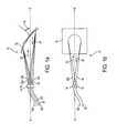
- FIG. 4 ais a side view of an integrated wavelength division multiplexing device having a single boot lens and a reflective concave diffraction grating in accordance with the present invention.
- FIG. 4 bis a top view of the integrated wavelength division multiplexing device shown in FIG. 4 a.
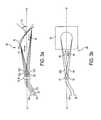
- FIG. 5 ais a side view of an integrated wavelength division multiplexing device having a prism, a boot lens, and a reflective concave diffraction grating in accordance with the present invention.
- FIG. 5 bis a top view of the integrated wavelength division multiplexing device shown in FIG. 5 a.
- FIG. 6 ais a side view of a wavelength division multiplexing device having a bi-convex focusing lens and a reflective concave diffraction grating in accordance with the present invention.
- FIG. 6 bis a top view of the integrated wavelength division multiplexing device shown in FIG. 6 a.
- FIG. 7 ais a side view of an integrated wavelength division multiplexing device having a bi-convex focusing lens, multiple boot lenses, and a reflective concave diffraction grating in accordance with the present invention.
- FIG. 7 bis a top view of the integrated wavelength division multiplexing device shown in FIG. 7 a.
- FIG. 8 ais a side view of a wavelength division multiplexing device having a reflective concave diffraction grating and an additional reflecting surface in accordance with the present invention.
- FIG. 8 bis a top view of the wavelength division multiplexing device shown in FIG. 8 a.
- FIG. 9is a side view of a wavelength division multiplexing device having a non-Littrow reflective concave diffraction grating in accordance with the present invention.
- FIGS. 1 a and 1 bthere are shown a side view and a top view, respectively, of a preferred embodiment of a wavelength division multiplexing device 10 in accordance with the present invention.
- the multiplexing device 10comprises a plurality of optical input fibers 12 , an input fiber coupling device 14 , a reflective concave diffraction grating 16 , an output fiber coupling device 18 , and a single optical output fiber 20 . All of the above-identified components of the multiplexing device 10 are disposed along an optical axis X-X of the multiplexing device 10 , as will be described in more detail below.
- optical input fibers 12 and the optical output fiber 20are single mode optical fibers.
- the present invention WDM devicescan also be used with multimode optical fibers.
- the multiplexing device 10is operating in the infrared (IR) region of the electromagnetic spectrum as a dense wavelength division multiplexing (DWDM) device (i.e., operating with data channels having channel spacings of 1 nm or less).
- DWDMdense wavelength division multiplexing
- the present invention WDM devicescan also be standard WDM devices (i.e., operating with data channels having channel spacings greater than 1 nm).
- the plurality of optical input fibers 12are grouped into a one-dimensional input fiber array (i.e., a 1 ⁇ 4 array is shown, but the input fiber array may include one hundred or more input fibers and is limited only by the spectral bandwidth of the diffraction grating and channel spacing, as described in more detail below) by the input fiber coupling device 14 , while the single optical output fiber 20 is secured to the output fiber coupling device 18 .
- Both the input fiber coupling device 14 and the output fiber coupling device 18are used for purposes of ease of optical fiber handling and precision placement, and can be formed of, for example, a silicon V-groove assembly. Referring to FIG.
- FIG. 1 cthere is shown a perspective end view of a portion of the multiplexing device 10 revealing how the plurality of optical input fibers 12 are grouped into the one-dimensional input fiber array by the input fiber coupling device 14 , and how the single optical output fiber 20 is secured to the output fiber coupling device 18 .
- FIG. 1 calso shows a monochromatic optical input beam 22 being transmitted from each of the plurality of optical input fibers 12 , and a single multiplexed, polychromatic optical output beam 24 being transmitted to the single optical output fiber 20 .
- Each of the monochromatic optical input beams 22 being transmitted from the plurality of optical input fibers 12is carrying a single channel of data at a unique wavelength, which is preferably, but not required to be, within the infrared (IR) region of the electromagnetic spectrum.
- the single channel of data that is being carried by each monochromatic optical input beam 22is superimposed on each corresponding unique wavelength by means (e.g., laser diodes connected to the plurality of optical input fibers 12 ), which are not shown here and which do not form a part of this invention, but are well known in the art.
- the unique wavelengths of the monochromatic optical input beams 22are appropriately preselected such that the data channels do not interfere with each other (i.e., there is sufficient channel spacing), and the optical transmission losses through both the optical input fibers 12 and the optical output fiber 20 are low, as is also well known in the art.
- the single multiplexed, polychromatic optical output beam 24 being transmitted to the single optical output fiber 20is carrying a plurality of channels of data at the unique wavelengths of each of the plurality of monochromatic optical input beams 22 .
- the plurality of monochromatic optical input beams 22are combined into the single multiplexed, polychromatic optical output beam 24 by the reflective concave diffraction grating 16 , as will be described in more detail below.
- the input fiber coupling device 14 and the output fiber coupling device 18are disposed offset from, but symmetrically about, the optical axis X-X of the multiplexing device 10 so as to insure that the single multiplexed, polychromatic optical output beam 24 is directed to the single optical output fiber 20 secured to the output fiber coupling device 18 , and not to any of the plurality of optical input fibers 12 secured to the input fiber coupling device 14 , or anywhere else.
- This offset spacing of the input fiber coupling device 14 and the output fiber coupling device 18is determined based upon the characteristics of the reflective concave diffraction grating 16 and the wavelengths of each of the monochromatic optical input beams 22 .
- each of the plurality of monochromatic optical input beams 22are transmitted from their corresponding optical input fiber 12 into the air space between the input fiber coupling device 14 and the reflective concave diffraction grating 16 .
- the plurality of monochromatic optical input beams 22are expanded in diameter until they become incident upon the reflective concave diffraction grating 16 .
- the reflective concave diffraction grating 16operates to angularly disperse the plurality of monochromatic optical input beams 22 by an amount that is dependent upon the wavelength of each of the plurality of monochromatic optical input beams 22 .
- the reflective concave diffraction grating 16is oriented at a special angle (i.e., the Littrow diffraction angle, ⁇ i ) relative to the optical axis X-X of the multiplexing device 10 in order to obtain the Littrow diffraction condition for an optical beam having a wavelength that lies within or near the wavelength range of the plurality of monochromatic optical input beams 22 .
- the Littrow diffraction conditionrequires that an optical beam be incident on and reflected back from a reflective diffraction grating at the exact same angle. Therefore, it will be readily apparent to one skilled in the art that the reflective concave diffraction grating 16 is used to obtain near-Littrow diffraction for each of the plurality of monochromatic optical input beams 22 .
- the Littrow diffraction angle, ⁇ iis determined by the well-known diffraction grating equation,
- ⁇ iis the common angle of incidence and reflection.
- variables affecting the Littrow diffraction angle, ⁇ iinclude the desired grating diffraction order, the grating pitch (i.e., the number of grating grooves per millimeter), the grating blaze angle, the number of data channels, the spacing of the data channels, and the wavelength range of the multiplexing device 10 .
- the reflective concave diffraction grating 16can be formed from a variety of ;materials and by a variety of techniques.
- the reflective concave diffraction grating 16can be formed by a three-dimensional hologram in a polymer medium, or by replicating a mechanically ruled master with a polymer material. In both cases, the polymer is overcoated with a thin, highly reflective metal layer such as, for example, gold or aluminum.
- the reflective concave diffraction grating 16can be formed by chemically etching into a concave material such as, for example, glass or silicon, which is also overcoated with a thin, highly reflective metal layer such as, for example, gold or aluminum.
- the reflective concave diffraction grating 16operates to angularly disperse the plurality of collimated, monochromatic optical input beams 22 .
- the reflective concave diffraction grating 16removes the angular separation of the plurality of monochromatic optical input beams 22 , and reflects a single polychromatic optical output beam 24 back towards the output fiber coupling device 18 , and hence towards the single optical output fiber 20 secured therein.
- the single polychromatic optical output beam 24contains each of the unique wavelengths of the plurality of monochromatic optical input beams 22 .
- the single polychromatic optical output beam 24is a single multiplexed, polychromatic optical output beam 24 .
- the single multiplexed, polychromatic optical output beam 24is focused down towards the output fiber coupling device 18 , and hence towards the single optical output fiber 20 secured therein, whereby the single multiplexed, polychromatic optical output beam 24 is coupled into the single optical output fiber 20 for transmission therethrough.
- the plurality of optical input fibers 12could be replaced in the multiplexing device 10 by a corresponding plurality of laser diodes 32 secured within a coupling device 34 , such as shown in FIG. 2 a .
- the coupling device 34performs a similar function to the input fiber coupling device 14 , that being to precisely group the plurality of laser diodes 32 into a one-dimensional input array.
- the plurality of laser diodes 32are used in place of the plurality of optical input fibers 12 to transmit the plurality of monochromatic optical input beams 22 to the multiplexing device 10 .
- the array of laser diodes 32may operate alone, or may be used with appropriate focusing lenses to provide the best coupling and the lowest amount of signal loss and channel crosstalk.
- the multiplexing device 10may be operated in a converse configuration as a demultiplexing device 40 , such as shown in FIGS. 3 a and 3 b .
- the demultiplexing device 40is physically identical to the multiplexing device 10 , and is therefore numerically identified as such. However, the demultiplexing device 40 is functionally opposite to the multiplexing device 10 .
- a single multiplexed, polychromatic optical input beam 42is transmitted from the single optical fiber 20 , and a plurality of monochromatic optical output beams 44 are transmitted to the plurality of optical fibers 12 , wherein each one of the plurality of monochromatic optical output beams 44 is transmitted to a corresponding one of the plurality of optical fibers 12 .
- the single multiplexed, polychromatic optical input beam 42is simultaneously carrying a plurality of channels of data, each at a unique wavelength which is preferably, but not required to be, within the infrared (IR) region of the electromagnetic spectrum.
- the plurality of monochromatic optical output beams 44are each carrying a single channel of data at a corresponding one of the unique wavelengths of the single multiplexed, polychromatic optical input beam 42 .
- the single multiplexed, polychromatic optical input beam 42is separated into the plurality of monochromatic optical output beams 44 by the reflective concave diffraction grating 16 .
- the reflective concave diffraction grating 16operates to perform a demultiplexing function.
- the plurality of optical fibers 12could be replaced in the demultiplexing device 40 by a corresponding plurality of photodetectors 36 secured within a coupling device 38 , such as shown in FIG. 2 b .
- the coupling device 38performs a similar function to the fiber coupling device 14 , that being to precisely group the plurality of photodetectors 36 into a one-dimensional input array.
- the plurality of photodetectors 36are used in place of the plurality of optical fibers 12 to receive the plurality of monochromatic optical output beams 44 from the demultiplexing device 40 .
- the array of photodetectors 36may operate alone, or may be used with appropriate focusing lenses to provide the best coupling and the lowest amount of signal loss and channel crosstalk.
- FIGS. 4 a and 4 bthere are shown a side view and a top view, respectively, of an alternate embodiment of a wavelength division multiplexing device 50 in accordance with the present invention.
- the multiplexing device 50is physically identical to the multiplexing device 10 , except for the addition of a boot lens 52 between the fiber coupling devices 14 and 18 and the reflective concave diffraction grating 16 .
- the boot lens 52has a planar front surface 52 a for mating with the fiber coupling devices 14 and 18 and the associated secured optical fibers 12 and 20 , respectively.
- the fiber coupling devices 14 and 18 and the secured optical fibers 12 and 20may be either abutted against the planar front surface 52 a or affixed to the planar front surface 52 a using optical cement or some other optically transparent bonding technique, depending upon system mobility requirements and optical beam alignment and loss considerations.
- the boot lens 52also has a convex back surface 52 b .
- the reflective concave diffraction grating 16can be formed using a separate material, and this material can then be joined or affixed to the convex back surface 52 b of the boot lens 52 using optical cement or some other optically transparent bonding technique.
- the reflective concave diffraction grating 16can be formed directly on the convex back surface 52 b of the boot lens 52 , thereby avoiding the joining or affixing of the reflective concave diffraction grating 16 to the convex back surface 52 b of the boot lens 52 .
- the reflective concave diffraction grating 16 and the boot lens 52are integrated to form a compact, rigid, and environmentally and thermally stable multiplexing device 50 .
- the integrated nature of this multiplexing device 50is particularly useful for maintaining component alignment, which provides long-term performance in contrast to some non-integrated air-spaced devices that characteristically degrade in alignment and therefore performance over time.
- the multiplexing device 50is functionally identical to the multiplexing device 10 , except for a slight decrease in optical beam transmission efficiency due to the addition of the boot lens 52 . However, even with this slight decrease in optical beam transmission efficiency, the optical performance of the multiplexing device 50 is still exceptional.
- FIGS. 5 a and 5 bthere are shown a side view and a top view, respectively, of an alternate embodiment of a wavelength division multiplexing device 60 in accordance with the present invention.
- the multiplexing device 60is physically identical to the multiplexing device 50 , except that instead of the single boot lens 52 in the multiplexing device 50 , the multiplexing device 60 has a prism 62 disposed adjacent the fiber coupling devices 14 and 18 and a boot lens 64 disposed adjacent the reflective concave diffraction grating 16 .
- the prism 62has a planar front surface 62 a for mating with the fiber coupling devices 14 and 18 and the associated secured optical fibers 12 and 20 , respectively.
- the fiber coupling devices 14 and 18 and the secured optical fibers 12 and 20may be either abutted against the planar front surface 62 a or affixed to the planar front surface 62 a using optical cement or some other optically transparent bonding technique, depending upon system mobility requirements and optical beam alignment and loss considerations.
- the prism 62also has a planar back surface 62 b for mating with a planar front surface 64 a of the boot lens 64 .
- the planar back surface 62 b of the prism 62is typically joined or affixed to the planar front surface 64 a of the boot lens 64 using optical cement or some other optically transparent bonding technique.
- the boot lens 64has a convex back surface 64 b .
- the reflective concave diffraction grating 16can be formed using a separate material, and this material can then be joined or affixed to the convex back surface 64 b of the boot lens 64 using optical cement or some other optically transparent bonding technique.
- the reflective concave diffraction grating 16can be formed directly on the convex back surface 64 b of the boot lens 64 , thereby avoiding the joining or affixing of the reflective concave diffraction grating 16 to the convex back surface 64 b of the boot lens 64 .
- the reflective concave diffraction grating 16 and the boot lens 64are integrated along with the prism 62 to form a compact, rigid, and environmentally and thermally stable multiplexing device 60 .
- the integrated nature of this multiplexing device 60is particularly useful for maintaining component alignment, which provides long-term performance in contrast to some non-integrated air-spaced devices that characteristically degrade in alignment and therefore performance over time.
- the multiplexing device 60is functionally identical to the multiplexing device 10 , except for a slight decrease in optical beam transmission efficiency due to the addition of the prism 62 and the boot lens 64 . However, even with this slight decrease in optical beam transmission efficiency, the optical performance of the multiplexing device 60 is still exceptional.
- the multiplexing device 60is also functionally identical to the multiplexing device 50 , except for a slight increase in optical beam transmission efficiency due to the additional optical interface between the prism 62 and the boot lens 64 . Also, using the prism 62 allows the boot lens 64 to be shorter than the boot lens 52 in the multiplexing device 50 , thereby allowing for easier manufacturing of the boot lens 64 .
- either the prism 62 or the second boot lens 64may be removed from the multiplexing device 60 so as to create additional alternate embodiments (not shown) which also obtain exceptional optical performance while using the reflective concave diffraction grating 16 .
- FIGS. 6 a and 6 bthere are shown a side view and a top view, respectively, of an alternate embodiment of a wavelength division multiplexing device 70 in accordance with the present invention.
- the multiplexing device 70is physically identical to the multiplexing device 10 , except for the addition of a bi-convex focusing lens 72 so as to enhance the imaging of both the input optical beams 22 and output optical beam 24 within the multiplexing device 70 . That is, the bi-convex focusing lens 72 provides additional imaging capability, thereby increasing the fiber coupling efficiency (FCE) of the multiplexing device 70 .
- FCEfiber coupling efficiency
- the FCE of a WDM deviceexpresses the efficiency of only the optical system of the WDM device for each data channel, without taking into account the efficiency of the diffraction grating.
- further increases in the FCEcan typically be achieved using doublet, triplet, or even higher number lens configurations.
- a trade-offmust be made between an increase in the FCE and the additional cost associated with adding additional lenses, or fabricating lenses having additional curved surfaces.
- FIGS. 7 a and 7 bthere are shown a side view and a top view, respectively, of an alternate embodiment of a wavelength division multiplexing device 80 in accordance with the present invention.
- the multiplexing device 80is physically identical to the multiplexing device 70 , except for the addition of a first boot lens 82 between the fiber coupling devices 14 and 18 and the bi-convex focusing lens 72 , and a second boot lens 84 between the bi-convex focusing lens 72 and the reflective concave diffraction grating 16 .
- the first boot lens 82has a planar front surface 82 a for mating with the fiber coupling devices 14 and 18 and the associated secured optical fibers 12 and 20 , respectively.
- the fiber coupling devices 14 and 18 and the secured optical fibers 12 and 20may be either abutted against the planar front surface 82 a or affixed to the planar front surface 82 a using optical cement or some other optically transparent bonding technique, depending upon system mobility requirements and optical beam alignment and loss considerations.
- the first boot lens 82also has a concave back surface 82 b for mating with a convex front surface 72 a of the bi-convex focusing lens 72 .
- the concave back surface 82 b of the first boot lens 82is typically joined or affixed to the convex front surface 72 a of the bi-convex focusing lens 72 using optical cement or some other optically transparent bonding technique.
- the second boot lens 84has a concave front surface 84 a for mating with a convex back surface 72 b of the bi-convex focusing lens 72 .
- the concave front surface 84 a of the second boot lens 84is typically joined or affixed to the convex back surface 72 b of the bi-convex focusing lens 72 using optical cement or some other optically transparent bonding technique.
- the second boot lens 84also has a convex back surface 84 b .
- the reflective concave diffraction grating 16can be formed using a separate material, and this material can then be joined or affixed to the convex back surface 84 b of the second boot lens 84 using optical cement or some other optically transparent bonding technique.
- the reflective concave diffraction grating 16can be formed directly on the convex back surface 84 b of the second boot lens 84 , thereby avoiding the joining or affixing of the reflective concave diffraction grating 16 to the convex back surface 84 b of the second boot lens 84 .
- the reflective concave diffraction grating 16 and the second boot lens 84are integrated along with the bi-convex focusing lens 72 and the first boot lens 82 to form a compact, rigid, and environmentally and thermally stable multiplexing device 80 .
- the integrated nature of this multiplexing device 80is particularly useful for maintaining component alignment, which provides long-term performance in contrast to some non-integrated air-spaced devices that characteristically degrade in alignment and therefore performance over time.
- the multiplexing device 80is functionally identical to the multiplexing device 70 , except for a slight decrease in optical beam transmission efficiency due to the addition of the first boot lens 82 and the second boot lens 84 . However, even with this slight decrease in optical beam transmission efficiency, the optical performance of the multiplexing device 80 is still exceptional.
- first boot lens 82 or the second boot lens 84may be removed from the multiplexing device 80 , and/or the either the first boot lens 82 or the second boot lens 84 may be integrated with the bi-convex focusing lens 72 in the multiplexing device 80 so as to create additional alternate embodiments (not shown) which also obtain exceptional optical performance while using the reflective concave diffraction grating 16 .
- FIGS. 8 a and 8 bthere are shown a side view and a top view, respectively, of an alternate embodiment of a wavelength division multiplexing device 90 in accordance with the present invention.
- the multiplexing device 90differs from the previously described embodiments by using an additional reflecting surface 92 .
- the reflecting surface 92may be fabricated of any suitable highly reflective material such as, for example, aluminum or gold.
- the reflecting surface 92allows the multiplexing device 90 to be more compact by utilizing the space between the fiber coupling devices 14 and 18 and the reflective concave diffraction grating 16 in a more efficient manner.
- the reflecting surface 92receives the plurality of monochromatic optical input beams 22 from the corresponding plurality of optical input fibers 12 secured within the input fiber coupling device 14 , and reflects the plurality of monochromatic optical input beams 22 toward the reflective concave diffraction grating 16 .
- the reflecting surface 92also receives the single multiplexed, polychromatic optical output beam 24 from the reflective concave diffraction grating 16 , and reflects the single multiplexed, polychromatic optical output beam 24 toward the output fiber coupling device 18 where it becomes incident upon the single optical output fiber 20 .
- the single multiplexed, polychromatic optical output beam 24is then coupled into the single optical output fiber 20 for transmission therethrough.
- focusing lensesmay be added between the fiber coupling devices 14 and 18 and the reflecting surface 92 , and/or between the reflecting surface 92 and the reflective concave diffraction grating 16 .
- boot lenses and/or prismsmay be added to the multiplexing device 90 in accordance with the practices described above. The benefits and detriments associated with using these additional components are applicable to the multiplexing device 90 as would be the case with the embodiments described above.
- FIG. 9there is shown a side view of an alternate embodiment of a wavelength division multiplexing device 100 in accordance with the present invention.
- the multiplexing device 100differs from the previously described embodiments by using a reflective concave diffraction grating 102 that is configured to operate at reflecting angle that is different than the reflecting angle of the previously described embodiments.
- the reflective concave diffraction grating 102receives the plurality of monochromatic optical input beams 22 from the corresponding plurality of optical input fibers 12 secured within the input fiber coupling device 14 , removes the angular separation from the plurality of monochromatic optical input beams 22 , and reflects the single multiplexed, polychromatic optical output beam 24 toward the output fiber coupling device 18 where it becomes incident upon the single optical output fiber 20 .
- the single multiplexed, polychromatic optical output beam 24is then coupled into the single optical output fiber 20 for transmission therethrough.
- focusing lensesmay be added between the input fiber coupling device 14 and the reflective concave diffraction grating 102 , and/or between the reflective concave diffraction grating 102 and the output fiber coupling device 18 .
- boot lenses and/or prismsmay be added to the multiplexing device 100 in accordance with the practices described above. The benefits and detriments associated with using these additional components are applicable to the multiplexing device 100 as would be the case with the embodiments described above.
- the most significant benefitscome from obtaining exceptional optical performance while using a reflective concave diffraction grating in a multiplexing/demultiplexing device. That is, all of the above-described embodiments obtain exceptional optical performance while using a reflective concave diffraction grating.
- the use of a reflective concave diffraction grating in a multiplexing/demultiplexing devicealso yields reduced device cost, complexity, and manufacturing risk.
- the use of a reflective concave diffraction grating in a multiplexing/demultiplexing deviceallows for the construction of a family of simple, low cost, yet very powerful WDM devices, particularly for use in DWDM (i.e., high channel number) applications.
Landscapes
- Physics & Mathematics (AREA)
- General Physics & Mathematics (AREA)
- Optics & Photonics (AREA)
- Optical Couplings Of Light Guides (AREA)
Abstract
Description
Claims (28)
Priority Applications (1)
| Application Number | Priority Date | Filing Date | Title |
|---|---|---|---|
| US09/604,616US6434299B1 (en) | 1999-06-01 | 2000-06-27 | Wavelength division multiplexing/demultiplexing devices having concave diffraction gratings |
Applications Claiming Priority (5)
| Application Number | Priority Date | Filing Date | Title |
|---|---|---|---|
| US09/323,094US6263135B1 (en) | 1997-12-13 | 1999-06-01 | Wavelength division multiplexing/demultiplexing devices using high index of refraction crystalline lenses |
| US09/363,041US6243513B1 (en) | 1997-12-13 | 1999-07-29 | Wavelength division multiplexing/demultiplexing devices using diffractive optic lenses |
| US09/382,492US6404945B1 (en) | 1997-12-13 | 1999-08-25 | Wavelength division multiplexing/demultiplexing devices using homogeneous refractive index lenses |
| US09/392,670US6298182B1 (en) | 1997-12-13 | 1999-09-08 | Wavelength division multiplexing/demultiplexing devices using polymer lenses |
| US09/604,616US6434299B1 (en) | 1999-06-01 | 2000-06-27 | Wavelength division multiplexing/demultiplexing devices having concave diffraction gratings |
Related Parent Applications (1)
| Application Number | Title | Priority Date | Filing Date |
|---|---|---|---|
| US09/323,094Continuation-In-PartUS6263135B1 (en) | 1997-12-13 | 1999-06-01 | Wavelength division multiplexing/demultiplexing devices using high index of refraction crystalline lenses |
Publications (1)
| Publication Number | Publication Date |
|---|---|
| US6434299B1true US6434299B1 (en) | 2002-08-13 |
Family
ID=27502256
Family Applications (1)
| Application Number | Title | Priority Date | Filing Date |
|---|---|---|---|
| US09/604,616Expired - LifetimeUS6434299B1 (en) | 1999-06-01 | 2000-06-27 | Wavelength division multiplexing/demultiplexing devices having concave diffraction gratings |
Country Status (1)
| Country | Link |
|---|---|
| US (1) | US6434299B1 (en) |
Cited By (10)
| Publication number | Priority date | Publication date | Assignee | Title |
|---|---|---|---|---|
| US20030044577A1 (en)* | 2001-08-22 | 2003-03-06 | Lisa Dhar | Method and apparatus for multilayer optical articles |
| US20040208581A1 (en)* | 2001-11-02 | 2004-10-21 | David Li | Optical add-drop multiplexer |
| US20060127006A1 (en)* | 2004-12-14 | 2006-06-15 | Oh Kee Kwon | Tunable demultiplexer and tunable laser with optical deflector |
| US20070082179A1 (en)* | 2005-10-07 | 2007-04-12 | Wade James J | Method and apparatus for forming optical articles |
| US20070133649A1 (en)* | 2005-12-09 | 2007-06-14 | Kwon Oh K | Wavelength tunable light source |
| CN100337416C (en)* | 2002-09-28 | 2007-09-12 | 浙江大学 | Integrated de-multiplexer for use in sparse wave-division multiplexer |
| US20120269483A1 (en)* | 2007-11-05 | 2012-10-25 | Mossberg Thomas W | Highly efficient optical gratings with reduced thickness requirements and impedance-matching layers |
| US9176282B2 (en) | 2011-10-06 | 2015-11-03 | Valorbec S.E.C. | High efficiency mono-order concave diffraction grating |
| US10802184B2 (en) | 2014-04-28 | 2020-10-13 | Ii-Vi Delaware Inc. | Reflective diffraction gratings employing efficiency enhancement or etch barrier layers |
| US20240103224A1 (en)* | 2022-09-23 | 2024-03-28 | Apple Inc. | Optical Splitters with Reflective Surfaces |
Citations (77)
| Publication number | Priority date | Publication date | Assignee | Title |
|---|---|---|---|---|
| US4111524A (en) | 1977-04-14 | 1978-09-05 | Bell Telephone Laboratories, Incorporated | Wavelength division multiplexer |
| US4153330A (en) | 1977-12-01 | 1979-05-08 | Bell Telephone Laboratories, Incorporated | Single-mode wavelength division optical multiplexer |
| US4198117A (en) | 1976-12-28 | 1980-04-15 | Nippon Electric Co., Ltd. | Optical wavelength-division multiplexing and demultiplexing device |
| US4274706A (en) | 1979-08-30 | 1981-06-23 | Hughes Aircraft Company | Wavelength multiplexer/demultiplexer for optical circuits |
| US4279464A (en) | 1979-12-18 | 1981-07-21 | Northern Telecom Limited | Integrated optical wavelength demultiplexer |
| US4299488A (en) | 1979-11-23 | 1981-11-10 | Bell Telephone Laboratories, Incorporated | Time-division multiplexed spectrometer |
| US4343532A (en) | 1980-06-16 | 1982-08-10 | General Dynamics, Pomona Division | Dual directional wavelength demultiplexer |
| US4387955A (en) | 1981-02-03 | 1983-06-14 | The United States Of America As Represented By The Secretary Of The Air Force | Holographic reflective grating multiplexer/demultiplexer |
| US4479697A (en) | 1979-08-14 | 1984-10-30 | Kaptron, Inc. | Fiber optics communications modules |
| US4522462A (en) | 1983-05-27 | 1985-06-11 | The Mitre Corporation | Fiber optic bidirectional wavelength division multiplexer/demultiplexer with total and/or partial redundancy |
| US4583820A (en) | 1981-12-24 | 1986-04-22 | Instruments S.A. | Wavelength multiplexer/demultiplexer using optical fibers |
| US4622662A (en) | 1983-03-31 | 1986-11-11 | Instruments S.A. | Wavelength-selective multiplexer-demultiplexer |
| US4626069A (en) | 1979-04-21 | 1986-12-02 | U.S. Philips Corporation | Optical power divider |
| US4634215A (en) | 1983-03-16 | 1987-01-06 | Carl-Zeiss-Stiftung | Wavelength multi/demultiplexer |
| US4643519A (en) | 1983-10-03 | 1987-02-17 | International Telephone And Telegraph Corporation | Wavelength division optical multiplexer/demultiplexer |
| US4652080A (en) | 1982-06-22 | 1987-03-24 | Plessey Overseas Limited | Optical transmission systems |
| US4671607A (en) | 1982-12-08 | 1987-06-09 | Instruments, S.A. of France | Divided function optical component for optical teletransmissions |
| US4703472A (en)* | 1985-03-14 | 1987-10-27 | Carl-Zeiss-Stiftung | Wavelength multi/demultiplexer |
| US4707056A (en)* | 1984-12-21 | 1987-11-17 | Carl-Zeiss-Stiftung | Optical arrangement having a concave mirror or concave grating |
| US4708425A (en) | 1983-10-11 | 1987-11-24 | Lignes Telegraphiques Et Telephoniques Ltt | Bidirectional optical wavelength multiplexer-demultiplexer |
| US4726645A (en) | 1983-08-12 | 1988-02-23 | Mitsubishi Denki Kabushiki Kaisha | Optical coupler |
| US4740951A (en) | 1985-03-13 | 1988-04-26 | Commissariat A L'energie Atomique | Reversible device for the demultiplexing of several light signals in integrated optics |
| US4741588A (en) | 1981-09-07 | 1988-05-03 | U.S. Philips Corporation | Optical multiplexer and demultiplexer |
| US4744618A (en) | 1982-05-03 | 1988-05-17 | Siemens Aktiengesellschaft | Optical device for use as a multiplexer or demultiplexer in accordance with the diffraction grating principle |
| US4746186A (en) | 1983-12-15 | 1988-05-24 | U.S. Philips Corp. | Integrated optical multiplexer/demultiplexer utilizing a plurality of blazed gratings |
| US4748614A (en) | 1982-04-15 | 1988-05-31 | U.S. Philips Corporation | Optical wavelength-multiplexing and/or demultiplexing device |
| US4749247A (en) | 1986-04-03 | 1988-06-07 | The Mitre Corporation | Self-monitoring fiber optic link |
| US4752108A (en) | 1985-01-31 | 1988-06-21 | Alcatel N.V. | Integrated optical lens/coupler |
| US4760569A (en) | 1985-12-10 | 1988-07-26 | Siemens Aktiengesellschaft | Integrated optical multiplex-demultiplex module for optical communications transmission |
| US4763969A (en) | 1981-09-07 | 1988-08-16 | U.S. Philips Corporation | Adjustable optical demultiplexer |
| US4773063A (en) | 1984-11-13 | 1988-09-20 | University Of Delaware | Optical wavelength division multiplexing/demultiplexing system |
| US4784935A (en)* | 1986-04-04 | 1988-11-15 | Kernforschungszentrum Karlsruhe Gmbh | Method of producing a passive optical device including at least one reflection grating |
| US4786133A (en) | 1986-12-31 | 1988-11-22 | Commissariat A L'energie Atomique | Multiplexer-demultiplexer using an elliptical concave grating and produced in integrated optics |
| US4819224A (en) | 1985-03-20 | 1989-04-04 | Instruments S.A. | Wavelength multiplexer-demultiplexer corrected of geometric and chromatic aberrations |
| US4834485A (en) | 1988-01-04 | 1989-05-30 | Pencom International Corporation | Integrated fiber optics transmitter/receiver device |
| US4836634A (en) | 1980-04-08 | 1989-06-06 | Instruments Sa | Wavelength multiplexer/demultiplexer using optical fibers |
| US4857726A (en) | 1988-02-29 | 1989-08-15 | Allied-Signal Inc. | Method to decode relative spectral data |
| US4923271A (en) | 1989-03-28 | 1990-05-08 | American Telephone And Telegraph Company | Optical multiplexer/demultiplexer using focusing Bragg reflectors |
| US4926412A (en) | 1988-02-22 | 1990-05-15 | Physical Optics Corporation | High channel density wavelength division multiplexer with defined diffracting means positioning |
| US4930855A (en) | 1988-06-06 | 1990-06-05 | Trw Inc. | Wavelength multiplexing of lasers |
| US4934784A (en) | 1989-03-20 | 1990-06-19 | Kaptron, Inc. | Hybrid active devices coupled to fiber via spherical reflectors |
| US4999489A (en)* | 1989-03-17 | 1991-03-12 | The Boeing Company | Optical sensor using concave diffraction grating |
| US5026131A (en) | 1988-02-22 | 1991-06-25 | Physical Optics Corporation | High channel density, broad bandwidth wavelength division multiplexer with highly non-uniform Bragg-Littrow holographic grating |
| US5107359A (en) | 1988-11-25 | 1992-04-21 | Ricoh Company, Ltd. | Optical wavelength-divison multi/demultiplexer |
| US5170451A (en) | 1990-11-29 | 1992-12-08 | Kabushiki Kaisha Toshiba | Optical wdm (wavelength division multiplex) coupler |
| US5228103A (en) | 1992-08-17 | 1993-07-13 | University Of Maryland | Monolithically integrated wavelength division multiplexing laser array |
| US5278687A (en) | 1990-10-18 | 1994-01-11 | Physical Optics Corporation | Multiwavelength data communication fiber link |
| US5355237A (en) | 1993-03-17 | 1994-10-11 | The United States Of America As Represented By The Administrator Of The National Aeronautics And Space Administration | Wavelength-division multiplexed optical integrated circuit with vertical diffraction grating |
| US5363220A (en) | 1988-06-03 | 1994-11-08 | Canon Kabushiki Kaisha | Diffraction device |
| US5440416A (en) | 1993-02-24 | 1995-08-08 | At&T Corp. | Optical network comprising a compact wavelength-dividing component |
| US5442472A (en) | 1991-09-03 | 1995-08-15 | Scientific-Atlanta, Inc. | Fiber optic status monitoring system |
| US5450510A (en) | 1994-06-09 | 1995-09-12 | Apa Optics, Inc. | Wavelength division multiplexed optical modulator and multiplexing method using same |
| US5457573A (en) | 1993-03-10 | 1995-10-10 | Matsushita Electric Industrial Co., Ltd. | Diffraction element and an optical multiplexing/demultiplexing device incorporating the same |
| US5500910A (en) | 1994-06-30 | 1996-03-19 | The Whitaker Corporation | Passively aligned holographic WDM |
| US5513289A (en) | 1988-10-27 | 1996-04-30 | Omron Tateisi Electronics | Optical integrated lens/grating coupling device |
| US5526155A (en) | 1993-11-12 | 1996-06-11 | At&T Corp. | High-density optical wavelength division multiplexing |
| US5541774A (en) | 1995-02-27 | 1996-07-30 | Blankenbecler; Richard | Segmented axial gradient lens |
| US5555334A (en) | 1993-10-07 | 1996-09-10 | Hitachi, Ltd. | Optical transmission and receiving module and optical communication system using the same |
| US5583683A (en) | 1995-06-15 | 1996-12-10 | Optical Corporation Of America | Optical multiplexing device |
| US5606434A (en) | 1994-06-30 | 1997-02-25 | University Of North Carolina | Achromatic optical system including diffractive optical element |
| US5657406A (en) | 1994-09-23 | 1997-08-12 | United Technologies Corporation | Efficient optical wavelength multiplexer/de-multiplexer |
| US5703722A (en) | 1995-02-27 | 1997-12-30 | Blankenbecler; Richard | Segmented axial gradinet array lens |
| US5742416A (en) | 1996-03-28 | 1998-04-21 | Ciena Corp. | Bidirectional WDM optical communication systems with bidirectional optical amplifiers |
| US5745271A (en) | 1996-07-31 | 1998-04-28 | Lucent Technologies, Inc. | Attenuation device for wavelength multiplexed optical fiber communications |
| US5745612A (en) | 1995-12-18 | 1998-04-28 | International Business Machines Corporation | Wavelength sorter and its application to planarized dynamic wavelength routing |
| US5745270A (en) | 1996-03-28 | 1998-04-28 | Lucent Technologies Inc. | Method and apparatus for monitoring and correcting individual wavelength channel parameters in a multi-channel wavelength division multiplexer system |
| US5748815A (en) | 1995-09-01 | 1998-05-05 | France Telecom | Optical component adapted to monitor a multiwavelength link and add-drop multiplexer using this component, application to optical networks |
| US5748350A (en) | 1996-06-19 | 1998-05-05 | E-Tek Dynamics, Inc. | Dense wavelength division multiplexer and demultiplexer devices |
| US5768450A (en) | 1996-01-11 | 1998-06-16 | Corning Incorporated | Wavelength multiplexer/demultiplexer with varied propagation constant |
| US5777763A (en) | 1996-01-16 | 1998-07-07 | Bell Communications Research, Inc. | In-line optical wavelength reference and control module |
| US5880834A (en) | 1996-10-16 | 1999-03-09 | The United States Of America As Represented By The Administrator Of The National Aeronautics And Space Administration | Convex diffraction grating imaging spectrometer |
| US5999672A (en)* | 1997-12-13 | 1999-12-07 | Light Chip, Inc. | Integrated bi-directional dual axial gradient refractive index/diffraction grating wavelength division multiplexer |
| US6011884A (en)* | 1997-12-13 | 2000-01-04 | Lightchip, Inc. | Integrated bi-directional axial gradient refractive index/diffraction grating wavelength division multiplexer |
| US6243513B1 (en)* | 1997-12-13 | 2001-06-05 | Lightchip, Inc. | Wavelength division multiplexing/demultiplexing devices using diffractive optic lenses |
| US6263135B1 (en)* | 1997-12-13 | 2001-07-17 | Lightchip, Inc. | Wavelength division multiplexing/demultiplexing devices using high index of refraction crystalline lenses |
| US6289155B1 (en)* | 1997-12-13 | 2001-09-11 | Lightchip, Inc. | Wavelength division multiplexing/demultiplexing devices using dual high index of refraction crystalline lenses |
| US6298182B1 (en)* | 1997-12-13 | 2001-10-02 | Light Chip, Inc. | Wavelength division multiplexing/demultiplexing devices using polymer lenses |
- 2000
- 2000-06-27USUS09/604,616patent/US6434299B1/ennot_activeExpired - Lifetime
Patent Citations (77)
| Publication number | Priority date | Publication date | Assignee | Title |
|---|---|---|---|---|
| US4198117A (en) | 1976-12-28 | 1980-04-15 | Nippon Electric Co., Ltd. | Optical wavelength-division multiplexing and demultiplexing device |
| US4111524A (en) | 1977-04-14 | 1978-09-05 | Bell Telephone Laboratories, Incorporated | Wavelength division multiplexer |
| US4153330A (en) | 1977-12-01 | 1979-05-08 | Bell Telephone Laboratories, Incorporated | Single-mode wavelength division optical multiplexer |
| US4626069A (en) | 1979-04-21 | 1986-12-02 | U.S. Philips Corporation | Optical power divider |
| US4479697A (en) | 1979-08-14 | 1984-10-30 | Kaptron, Inc. | Fiber optics communications modules |
| US4274706A (en) | 1979-08-30 | 1981-06-23 | Hughes Aircraft Company | Wavelength multiplexer/demultiplexer for optical circuits |
| US4299488A (en) | 1979-11-23 | 1981-11-10 | Bell Telephone Laboratories, Incorporated | Time-division multiplexed spectrometer |
| US4279464A (en) | 1979-12-18 | 1981-07-21 | Northern Telecom Limited | Integrated optical wavelength demultiplexer |
| US4836634A (en) | 1980-04-08 | 1989-06-06 | Instruments Sa | Wavelength multiplexer/demultiplexer using optical fibers |
| US4343532A (en) | 1980-06-16 | 1982-08-10 | General Dynamics, Pomona Division | Dual directional wavelength demultiplexer |
| US4387955A (en) | 1981-02-03 | 1983-06-14 | The United States Of America As Represented By The Secretary Of The Air Force | Holographic reflective grating multiplexer/demultiplexer |
| US4741588A (en) | 1981-09-07 | 1988-05-03 | U.S. Philips Corporation | Optical multiplexer and demultiplexer |
| US4763969A (en) | 1981-09-07 | 1988-08-16 | U.S. Philips Corporation | Adjustable optical demultiplexer |
| US4583820A (en) | 1981-12-24 | 1986-04-22 | Instruments S.A. | Wavelength multiplexer/demultiplexer using optical fibers |
| US4748614A (en) | 1982-04-15 | 1988-05-31 | U.S. Philips Corporation | Optical wavelength-multiplexing and/or demultiplexing device |
| US4744618A (en) | 1982-05-03 | 1988-05-17 | Siemens Aktiengesellschaft | Optical device for use as a multiplexer or demultiplexer in accordance with the diffraction grating principle |
| US4652080A (en) | 1982-06-22 | 1987-03-24 | Plessey Overseas Limited | Optical transmission systems |
| US4671607A (en) | 1982-12-08 | 1987-06-09 | Instruments, S.A. of France | Divided function optical component for optical teletransmissions |
| US4634215A (en) | 1983-03-16 | 1987-01-06 | Carl-Zeiss-Stiftung | Wavelength multi/demultiplexer |
| US4622662A (en) | 1983-03-31 | 1986-11-11 | Instruments S.A. | Wavelength-selective multiplexer-demultiplexer |
| US4522462A (en) | 1983-05-27 | 1985-06-11 | The Mitre Corporation | Fiber optic bidirectional wavelength division multiplexer/demultiplexer with total and/or partial redundancy |
| US4726645A (en) | 1983-08-12 | 1988-02-23 | Mitsubishi Denki Kabushiki Kaisha | Optical coupler |
| US4643519A (en) | 1983-10-03 | 1987-02-17 | International Telephone And Telegraph Corporation | Wavelength division optical multiplexer/demultiplexer |
| US4708425A (en) | 1983-10-11 | 1987-11-24 | Lignes Telegraphiques Et Telephoniques Ltt | Bidirectional optical wavelength multiplexer-demultiplexer |
| US4746186A (en) | 1983-12-15 | 1988-05-24 | U.S. Philips Corp. | Integrated optical multiplexer/demultiplexer utilizing a plurality of blazed gratings |
| US4773063A (en) | 1984-11-13 | 1988-09-20 | University Of Delaware | Optical wavelength division multiplexing/demultiplexing system |
| US4707056A (en)* | 1984-12-21 | 1987-11-17 | Carl-Zeiss-Stiftung | Optical arrangement having a concave mirror or concave grating |
| US4752108A (en) | 1985-01-31 | 1988-06-21 | Alcatel N.V. | Integrated optical lens/coupler |
| US4740951A (en) | 1985-03-13 | 1988-04-26 | Commissariat A L'energie Atomique | Reversible device for the demultiplexing of several light signals in integrated optics |
| US4703472A (en)* | 1985-03-14 | 1987-10-27 | Carl-Zeiss-Stiftung | Wavelength multi/demultiplexer |
| US4819224A (en) | 1985-03-20 | 1989-04-04 | Instruments S.A. | Wavelength multiplexer-demultiplexer corrected of geometric and chromatic aberrations |
| US4760569A (en) | 1985-12-10 | 1988-07-26 | Siemens Aktiengesellschaft | Integrated optical multiplex-demultiplex module for optical communications transmission |
| US4749247A (en) | 1986-04-03 | 1988-06-07 | The Mitre Corporation | Self-monitoring fiber optic link |
| US4784935A (en)* | 1986-04-04 | 1988-11-15 | Kernforschungszentrum Karlsruhe Gmbh | Method of producing a passive optical device including at least one reflection grating |
| US4786133A (en) | 1986-12-31 | 1988-11-22 | Commissariat A L'energie Atomique | Multiplexer-demultiplexer using an elliptical concave grating and produced in integrated optics |
| US4834485A (en) | 1988-01-04 | 1989-05-30 | Pencom International Corporation | Integrated fiber optics transmitter/receiver device |
| US4926412A (en) | 1988-02-22 | 1990-05-15 | Physical Optics Corporation | High channel density wavelength division multiplexer with defined diffracting means positioning |
| US5026131A (en) | 1988-02-22 | 1991-06-25 | Physical Optics Corporation | High channel density, broad bandwidth wavelength division multiplexer with highly non-uniform Bragg-Littrow holographic grating |
| US4857726A (en) | 1988-02-29 | 1989-08-15 | Allied-Signal Inc. | Method to decode relative spectral data |
| US5363220A (en) | 1988-06-03 | 1994-11-08 | Canon Kabushiki Kaisha | Diffraction device |
| US4930855A (en) | 1988-06-06 | 1990-06-05 | Trw Inc. | Wavelength multiplexing of lasers |
| US5513289A (en) | 1988-10-27 | 1996-04-30 | Omron Tateisi Electronics | Optical integrated lens/grating coupling device |
| US5107359A (en) | 1988-11-25 | 1992-04-21 | Ricoh Company, Ltd. | Optical wavelength-divison multi/demultiplexer |
| US4999489A (en)* | 1989-03-17 | 1991-03-12 | The Boeing Company | Optical sensor using concave diffraction grating |
| US4934784A (en) | 1989-03-20 | 1990-06-19 | Kaptron, Inc. | Hybrid active devices coupled to fiber via spherical reflectors |
| US4923271A (en) | 1989-03-28 | 1990-05-08 | American Telephone And Telegraph Company | Optical multiplexer/demultiplexer using focusing Bragg reflectors |
| US5278687A (en) | 1990-10-18 | 1994-01-11 | Physical Optics Corporation | Multiwavelength data communication fiber link |
| US5170451A (en) | 1990-11-29 | 1992-12-08 | Kabushiki Kaisha Toshiba | Optical wdm (wavelength division multiplex) coupler |
| US5442472A (en) | 1991-09-03 | 1995-08-15 | Scientific-Atlanta, Inc. | Fiber optic status monitoring system |
| US5228103A (en) | 1992-08-17 | 1993-07-13 | University Of Maryland | Monolithically integrated wavelength division multiplexing laser array |
| US5440416A (en) | 1993-02-24 | 1995-08-08 | At&T Corp. | Optical network comprising a compact wavelength-dividing component |
| US5457573A (en) | 1993-03-10 | 1995-10-10 | Matsushita Electric Industrial Co., Ltd. | Diffraction element and an optical multiplexing/demultiplexing device incorporating the same |
| US5355237A (en) | 1993-03-17 | 1994-10-11 | The United States Of America As Represented By The Administrator Of The National Aeronautics And Space Administration | Wavelength-division multiplexed optical integrated circuit with vertical diffraction grating |
| US5555334A (en) | 1993-10-07 | 1996-09-10 | Hitachi, Ltd. | Optical transmission and receiving module and optical communication system using the same |
| US5526155A (en) | 1993-11-12 | 1996-06-11 | At&T Corp. | High-density optical wavelength division multiplexing |
| US5450510A (en) | 1994-06-09 | 1995-09-12 | Apa Optics, Inc. | Wavelength division multiplexed optical modulator and multiplexing method using same |
| US5606434A (en) | 1994-06-30 | 1997-02-25 | University Of North Carolina | Achromatic optical system including diffractive optical element |
| US5500910A (en) | 1994-06-30 | 1996-03-19 | The Whitaker Corporation | Passively aligned holographic WDM |
| US5657406A (en) | 1994-09-23 | 1997-08-12 | United Technologies Corporation | Efficient optical wavelength multiplexer/de-multiplexer |
| US5703722A (en) | 1995-02-27 | 1997-12-30 | Blankenbecler; Richard | Segmented axial gradinet array lens |
| US5541774A (en) | 1995-02-27 | 1996-07-30 | Blankenbecler; Richard | Segmented axial gradient lens |
| US5583683A (en) | 1995-06-15 | 1996-12-10 | Optical Corporation Of America | Optical multiplexing device |
| US5748815A (en) | 1995-09-01 | 1998-05-05 | France Telecom | Optical component adapted to monitor a multiwavelength link and add-drop multiplexer using this component, application to optical networks |
| US5745612A (en) | 1995-12-18 | 1998-04-28 | International Business Machines Corporation | Wavelength sorter and its application to planarized dynamic wavelength routing |
| US5768450A (en) | 1996-01-11 | 1998-06-16 | Corning Incorporated | Wavelength multiplexer/demultiplexer with varied propagation constant |
| US5777763A (en) | 1996-01-16 | 1998-07-07 | Bell Communications Research, Inc. | In-line optical wavelength reference and control module |
| US5742416A (en) | 1996-03-28 | 1998-04-21 | Ciena Corp. | Bidirectional WDM optical communication systems with bidirectional optical amplifiers |
| US5745270A (en) | 1996-03-28 | 1998-04-28 | Lucent Technologies Inc. | Method and apparatus for monitoring and correcting individual wavelength channel parameters in a multi-channel wavelength division multiplexer system |
| US5748350A (en) | 1996-06-19 | 1998-05-05 | E-Tek Dynamics, Inc. | Dense wavelength division multiplexer and demultiplexer devices |
| US5745271A (en) | 1996-07-31 | 1998-04-28 | Lucent Technologies, Inc. | Attenuation device for wavelength multiplexed optical fiber communications |
| US5880834A (en) | 1996-10-16 | 1999-03-09 | The United States Of America As Represented By The Administrator Of The National Aeronautics And Space Administration | Convex diffraction grating imaging spectrometer |
| US5999672A (en)* | 1997-12-13 | 1999-12-07 | Light Chip, Inc. | Integrated bi-directional dual axial gradient refractive index/diffraction grating wavelength division multiplexer |
| US6011884A (en)* | 1997-12-13 | 2000-01-04 | Lightchip, Inc. | Integrated bi-directional axial gradient refractive index/diffraction grating wavelength division multiplexer |
| US6243513B1 (en)* | 1997-12-13 | 2001-06-05 | Lightchip, Inc. | Wavelength division multiplexing/demultiplexing devices using diffractive optic lenses |
| US6263135B1 (en)* | 1997-12-13 | 2001-07-17 | Lightchip, Inc. | Wavelength division multiplexing/demultiplexing devices using high index of refraction crystalline lenses |
| US6289155B1 (en)* | 1997-12-13 | 2001-09-11 | Lightchip, Inc. | Wavelength division multiplexing/demultiplexing devices using dual high index of refraction crystalline lenses |
| US6298182B1 (en)* | 1997-12-13 | 2001-10-02 | Light Chip, Inc. | Wavelength division multiplexing/demultiplexing devices using polymer lenses |
Non-Patent Citations (52)
| Title |
|---|
| A. Cohen et al., Active management of 100-GHz-spaced WDM channels, Optical Fiber Communication Conference and the International Conference on Integrated Optics and Optical Fiber Communication, Technical Digest, Conference Edition (Feb. 24, 1999). |
| A. Koonen, A Compact Wavelength Demultiplexer Using Both Interference Filters and a Diffraction Grating, European Conference of Optical Communication, Conference Proceedings (Sep. 8-11, 1981). |
| A. Livanos et al., Chirped-grating demultiplexers in dielectric waveguides, Applied Physics Letters, vol. 30, No. 10 (May 1977). |
| A. Nicia, Wavelength Multiplexing and Demultiplexing Systems for Singlemode and Multimode Fibers, Conference Proceedings, European Conference on Optical Communication (Sep. 8-11, 1981). |
| A. Stavdas et al., Design of a holographic concave grating used as a multiplexer/demultiplexer in dense wavelength-routed optical networks with subnanometer channel spacing, Journal of Modern Optics, vol. 42, No. 9, pp. 1863-1874 (Sep. 1995). |
| A. Stavdas et al., Free-Space Aberration-Corrected Diffraction Grating Demultiplexer for Application in Densely-Spaced, Subnanometer Wavelength Routed Optical Networks, IEEE Electronic Letters, vol. 31, No. 16, pp. 1368-1370 (Aug. 1995). |
| A. Willner et al., 2-D WDM Optical Interconnections Using Multiple-Wavelength VCSEL's for Simultaneous and Reconfigurable Communication Among Many Planes, IEEE Phoyonics Technology Letters, vol. 5, No. 7 (Jul. 1993). |
| Adrian Meldrum, C- and L-band Channel Monitoring, Lightwave Special Reports, pp. 68-72 (Feb. 2000). |
| B. Hillerich et al., Wide Passband Grating Multiplexer for Multimode Fibers, Journal of Lightwave Technology, vol. LT-3, No. 3 (Jun. 1985). |
| B. Keyworth et al., Low Loss, Temperature Stable Diffraction Grating Wavelength (DE) Multiplexer, National Fiber Optic Engineers Conference, Technical Proceedings, vol. I (Sep. 13-17, 1998). |
| B. Moslehi et al., Fiber-optic wavelength-division multiplexing and demultiplexing using volume holographic gratings, Optics Letters, vol. 14, No. 19 (Oct. 1, 1989). |
| B.D. Metcalf et al., High-capacity wavelength demultiplexing with a large-diameter GRIN rod lens, Applied Optics, vol. 21, No. 5 (Mar. 1, 1982). |
| C. Koeppen, et al., High Resolution Fiber Grating Optical Network Monitor, National Fiber Optic Engineers Conference, Technical Proceedings, vol. II (Sep. 13-17, 1998). |
| C. Zhou et al., Four Channel Multimode Wavelength Division Demultiplexer (WDM) System Based on Surface-normal Volume Holographic Gratings and Substrate-guided Waves, SPIE, vol. 3288. |
| D. Maystre et al., Optimization of wavelength demultiplexer in fiber optics using gold echelette gratings, SPIE vol. 503, Application, Theory, and Fabrication of Periodic Structures (1984). |
| D. Wisely, High performance 32 channel HDWDM multiplexer with 1nm channels spacing and 0.7nm bandwidth, SPIE, vol. 1578, Fiber Networks for Telephony and CATV (1991). |
| D.R. Wisely, 32 Channel WDM Multiplexer with 1nm Channel Spacing and 0.7 nm Bandwidth, Electronics Letters, vol. 27, No. 6, pp. 520-521 (Mar. 14, 1991). |
| G. R. Harrison, Ph.D., Sc.D. et al., Practical Spectroscopy, Chapter 4-Diffraction-Grating Spectrographs, Prentice-Hall (1948). |
| G. Winzer, Wavelength Multiplexing Components-A Review of Single-Mode Devices and their Applications, Journal of Lightwave Technology, vol. LT-2, No. 4 (Aug. 1984). |
| G.D. Khoe, New Integrated Subscriber Star Network Combining Maximum Versatility With Minimum Costs of Installation and Maintenance, European Conference on Optical Communication, Conference Proceedings, Copenhagen, Bella Center (Sep. 8-11, 1981). |
| H. Ishio et al., Review and Status of Wavelength-Division-Multiplexing Technology and Its Application, Journal of Lightwave Technology, vol. LT-2, No. 4 (Aug. 1984). |
| H. Obara et al., Star Coupler Based WDM Switch Employing Tunable Devices With Reduced Tunability Range, Electronic Letters, vol. 28, No. 13 (Jun. 1992). |
| I. Nishi et al., Broad Passband Multi/Demultiplexer for Multimode Fibers Using a Diffraction Grating and Retroreflectors, Journal of Lightwave Technology, vol. LT-5, No. 12 (Dec. 1987). |
| J. Conradi et al., Laser Based WDM Multichannel Video Transmission System, Electronic Letters, vol. 17, No. 2 (Jan. 22, 1981). |
| J. Laude et al., Stimax, A Grating Multiplexer for Monomode or Multimode Fibers, Ninth European Conference on Optical Communication-ECOC83, Geneva, Switzerland (Oct. 23-26, 1983). |
| J. Laude et al., Wavelength division multiplexing/demultiplexing (WDM) using diffraction gratings, SPIE, vol. 503, Application, Theory, and Fabrication of Periodic Structures (1984). |
| J. Lipson et al., A Four-Channel Lightwave Subsystem Using Wavelength Division Multiplexing, IEEE Journal of Lightwave Technology, vol. LT-3, No. 1 (Feb. 1985). |
| J. Lipson et al., A Six-Channel Wavelength Multiplexer and Demultiplexer for Single Mode Systems, Journal of Lightwave Technology, vol. LT-3, No. 5 (Oct. 1985). |
| J. Lipson et al., Low-Loss Wavelength Division Multiplexing (WDM) Devices for Single-Mode Systems, Journal of Lightwave Technology, vol. LT-1, No. 2 (Jun. 1983). |
| J.P. Laude, Wavelength Division Multiplexing, pp. 116-117, (1993). |
| K. Aoyama et al., Low-loss optical demultiplexer for WDM system in the 0.8 mum wavelength region, Applied Optics, vol. 18, No. 15 (Aug. 15, 1979). |
| K. Aoyama et al., Low-loss optical demultiplexer for WDM system in the 0.8 μm wavelength region, Applied Optics, vol. 18, No. 15 (Aug. 15, 1979). |
| K. Aoyama et al., Optical demultiplexer for a wavelength division multiplexing system, Applied Optics, vol. 18, No. 8 (Apr. 15, 1979). |
| K. Kobayashi et al., Microoptic Grating Multiplexers and Optical Isolators for Fibers-Optic Communications, Journal of Quantum Electronics, vol. QE-16, No. 1 (Jan. 1980). |
| M. Li et al., Two-channel surface-normal wavelength demultiplexer using substrate guided waves in conjuction with numtiplexed waveguide holograms, Appl. Phys. Lett., vol. 66, No. 3 (Jan. 1995). |
| M. Seki et al., 20-Channel Micro-Optic Grating Demultiplexer for 1.1-1.6um Band Using a Small Focusing Parameter Graded-Index Rod Lens, Electronics Letters, vol. 18, No. 6 (Mar. 18, 1982). |
| M. Wang et al., Five Channel Polymer Waveguide Wavelength Division Demultiplexer for the Near Infrared, IEEE Photonics Technology Letters, vol. 3, No. 1 (Jan. 1991). |
| M. Wu et al., Design Considerations for Rowland Circle Grating Used in Photonic Integrated Devices for WDM Applications, Journal of Lightwave Technology, vol. 12, No. 11 (Nov. 1994). |
| M.J. Cohen, et al. InGaAs photodiode arrays for DWDM monitoring and receiving, Lightwave, pp. 99-101 (Aug. 1999). |
| R. Watanabe et al., Optical Demuliplexer Using Concave Grating in 0.7-0.9 um Wavelength Region, Electronics Letters, vol. 16, No. 3 (Jan. 31, 1980). |
| R. Watanabe et al., Optical Grating Multiplexer in the 1.1-1.5mm Wavelength Region, Electronics Letters, vol. 16, No. 3 (Jan. 31, 1980). |
| Sami Hendow, et al., Performance Monitors Enable Remote Channel Management, Lightwave Special Reports, pp. 62-66 and 72 (Feb. 2000). |
| T. Lingelsheim et al., Fabrication of micro-optical wavelength division multiplexer (WDM) gratings on glass using an ion etching technique, SPIE vol. 503, Application, Theory, and Fabrication of Periodic Structures (1984). |
| T. Miki et al., Viabilities of the wavelength-division-multiplexing transmission system over an optical fiber cable, IEEE Transactions on Communications, vol. Com-26, No. 7 (Jul. 1978). |
| W. J. Tomlinson et al., Optical wavelength-division-multiplexer for the 1-1.4 mum spectral region, Electronics Letters, vol. 14, No. 11 (May 25, 1973). |
| W. J. Tomlinson et al., Optical wavelength-division-multiplexer for the 1-1.4 μm spectral region, Electronics Letters, vol. 14, No. 11 (May 25, 1973). |
| W. J. Tomlinson, Applications of GRIN-rod lenses in optical fiber communication systems, Applied Optics, vol. 19, No. 7 (Apr. 1, 1980). |
| W. J. Tomlinson, Wavelength multiplexing in multimode optical fibers, Applied Optics, vol. 16, No. 8 (Aug. 1977). |
| W.J. Tomlinson et al., Optical multiplexer for multimode fiber transmission systems, Appl. Phys. Lett., vol. 31, No. 3 (Aug. 1977). |
| Y. Fujii et al., Optical Demultiplexer Using a Silison Echelette Grating, IEEE Journal of Quantum Electronics, vol. QE-16, No. 2 (Feb. 1980). |
| Y. Fujii et al., Optical Demultiplexer Utilizing an Ebert Mounting Silicon Grating, Journal of Lightwave Technology, vol. LT-2, No. 5 (Oct. 1984). |
| Y. Huang et al., Wavelength-division-multiplexing and -demultiplexing by using a substrate-mode grating pair, Optics Letters, vol. 17, No. 22 (Nov. 15, 1992). |
Cited By (15)
| Publication number | Priority date | Publication date | Assignee | Title |
|---|---|---|---|---|
| US7112359B2 (en)* | 2001-08-22 | 2006-09-26 | Inphase Technologies, Inc. | Method and apparatus for multilayer optical articles |
| US20030044577A1 (en)* | 2001-08-22 | 2003-03-06 | Lisa Dhar | Method and apparatus for multilayer optical articles |
| US20040208581A1 (en)* | 2001-11-02 | 2004-10-21 | David Li | Optical add-drop multiplexer |
| US7010228B2 (en)* | 2001-11-02 | 2006-03-07 | Hon Hai Precision Ind. Co., Ltd. | Optical add-drop multiplexer |
| CN100337416C (en)* | 2002-09-28 | 2007-09-12 | 浙江大学 | Integrated de-multiplexer for use in sparse wave-division multiplexer |
| US20060127006A1 (en)* | 2004-12-14 | 2006-06-15 | Oh Kee Kwon | Tunable demultiplexer and tunable laser with optical deflector |
| US7136553B2 (en)* | 2004-12-14 | 2006-11-14 | Electronics And Telecommunications Research Institute | Tunable demultiplexer and tunable laser with optical deflector |
| US20070082179A1 (en)* | 2005-10-07 | 2007-04-12 | Wade James J | Method and apparatus for forming optical articles |
| US20070133649A1 (en)* | 2005-12-09 | 2007-06-14 | Kwon Oh K | Wavelength tunable light source |
| US20120269483A1 (en)* | 2007-11-05 | 2012-10-25 | Mossberg Thomas W | Highly efficient optical gratings with reduced thickness requirements and impedance-matching layers |
| US8989537B2 (en)* | 2007-11-05 | 2015-03-24 | Lightsmyth Technologies, Inc. | Highly efficient optical gratings with reduced thickness requirements and impedance-matching layers |
| US20150185413A1 (en)* | 2007-11-05 | 2015-07-02 | Lightsmyth Technologies, Inc. | Highly efficient optical gratings with reduced thickness requirements and impedance-matching layers |
| US9176282B2 (en) | 2011-10-06 | 2015-11-03 | Valorbec S.E.C. | High efficiency mono-order concave diffraction grating |
| US10802184B2 (en) | 2014-04-28 | 2020-10-13 | Ii-Vi Delaware Inc. | Reflective diffraction gratings employing efficiency enhancement or etch barrier layers |
| US20240103224A1 (en)* | 2022-09-23 | 2024-03-28 | Apple Inc. | Optical Splitters with Reflective Surfaces |
Similar Documents
| Publication | Publication Date | Title |
|---|---|---|
| US6271970B1 (en) | Wavelength division multiplexing/demultiplexing devices using dual homogeneous refractive index lenses | |
| US5999672A (en) | Integrated bi-directional dual axial gradient refractive index/diffraction grating wavelength division multiplexer | |
| US6011884A (en) | Integrated bi-directional axial gradient refractive index/diffraction grating wavelength division multiplexer | |
| US6289155B1 (en) | Wavelength division multiplexing/demultiplexing devices using dual high index of refraction crystalline lenses | |
| US6343169B1 (en) | Ultra-dense wavelength division multiplexing/demultiplexing device | |
| US6263135B1 (en) | Wavelength division multiplexing/demultiplexing devices using high index of refraction crystalline lenses | |
| US6243513B1 (en) | Wavelength division multiplexing/demultiplexing devices using diffractive optic lenses | |
| US6181853B1 (en) | Wavelength division multiplexing/demultiplexing device using dual polymer lenses | |
| JPS61113009A (en) | Optical multiplexer/demultiplexer | |
| US6236780B1 (en) | Wavelength division multiplexing/demultiplexing devices using dual diffractive optic lenses | |
| JPS5844414A (en) | Wavelength multiplexer or wavelength demultiplexer | |
| US6434299B1 (en) | Wavelength division multiplexing/demultiplexing devices having concave diffraction gratings | |
| US6829096B1 (en) | Bi-directional wavelength division multiplexing/demultiplexing devices | |
| US6298182B1 (en) | Wavelength division multiplexing/demultiplexing devices using polymer lenses | |
| US6404945B1 (en) | Wavelength division multiplexing/demultiplexing devices using homogeneous refractive index lenses | |
| JP2003066269A (en) | WDM optical device and WDM optical transmission module | |
| JP2006091315A (en) | Optical multiplexer / demultiplexer and wavelength division multiplexing optical transmission module | |
| JP4696521B2 (en) | Demultiplexer, optical waveguide, and wavelength division multiplexing optical transmission module | |
| JPS59178423A (en) | Optical multiplexer/demultiplexer | |
| MXPA00005783A (en) | Integrated bi-directional axial gradient refractive index/diffraction grating wavelength division multiplexer |
Legal Events
| Date | Code | Title | Description |
|---|---|---|---|
| AS | Assignment | Owner name:LIGHTCHIP, INC., NEW HAMPSHIRE Free format text:ASSIGNMENT OF ASSIGNORS INTEREST;ASSIGNORS:YUDIN, YURI A.;SOKOLSKIY, MIKHAIL N.;WADE, ROBERT K.;REEL/FRAME:010897/0568;SIGNING DATES FROM 20000610 TO 20000619 | |
| AS | Assignment | Owner name:CONFLUENT PHOTONICS CORPORATION, MASSACHUSETTS Free format text:ASSIGNMENT OF ASSIGNORS INTEREST;ASSIGNOR:LIGHTCHIP, INC.;REEL/FRAME:013578/0269 Effective date:20021008 | |
| REMI | Maintenance fee reminder mailed | ||
| FPAY | Fee payment | Year of fee payment:4 | |
| SULP | Surcharge for late payment | ||
| AS | Assignment | Owner name:SQUARE 1 BANK, NORTH CAROLINA Free format text:SECURITY AGREEMENT;ASSIGNOR:CONFLUENT PHOTONICS CORPORATION;REEL/FRAME:020599/0574 Effective date:20060605 | |
| REMI | Maintenance fee reminder mailed | ||
| LAPS | Lapse for failure to pay maintenance fees | ||
| REIN | Reinstatement after maintenance fee payment confirmed | ||
| FP | Lapsed due to failure to pay maintenance fee | Effective date:20100813 | |
| FEPP | Fee payment procedure | Free format text:PETITION RELATED TO MAINTENANCE FEES GRANTED (ORIGINAL EVENT CODE: PMFG); ENTITY STATUS OF PATENT OWNER: SMALL ENTITY | |
| FPAY | Fee payment | Year of fee payment:8 | |
| SULP | Surcharge for late payment | ||
| PRDP | Patent reinstated due to the acceptance of a late maintenance fee | Effective date:20110829 | |
| STCF | Information on status: patent grant | Free format text:PATENTED CASE | |
| FPAY | Fee payment | Year of fee payment:12 | |
| AS | Assignment | Owner name:CONFLUENT PHOTONICS CORPORATION, CALIFORNIA Free format text:RELEASE BY SECURED PARTY;ASSIGNOR:PACIFIC WESTERN BANK (SUCCESSOR BY MERGER TO SQUARE 1 BANK);REEL/FRAME:049738/0749 Effective date:20190712 | |
| AS | Assignment | Owner name:AUXORA, INC., CALIFORNIA Free format text:ASSIGNMENT OF ASSIGNORS INTEREST;ASSIGNOR:CONFLUENT PHOTONICS CORPORATION;REEL/FRAME:050081/0351 Effective date:20161127 |